1
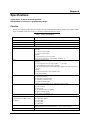
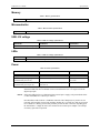
USB-4301 9513-based Counter/Timer User's Guide Document Revision 2, January, 2007 © Copyright 2007, Measurement Computing Corporation Your new Measurement Computing product comes with a fantastic extra — Management committed to your satisfaction! Refer to www.mccdaq.com/execteam.html for the names, titles, and contact information of each key executive at Measurement Computing. Thank you for choosing a Measurement Computing product—and congratulations! You own the finest, and you can now enjoy the protection of the most comprehensive warranties and unmatched phone tech support. It’s the embodiment of our mission: To provide PC-based data acquisition hardware and software that will save time and save money. Simple installations minimize the time between setting up your system and actually making measurements. We offer quick and simple access to outstanding live FREE technical support to help integrate MCC products into a DAQ system. Lifetime warranty: Every hardware product manufactured by Measurement Computing Corporation is warranted against defects in materials or workmanship for the life of the product. Products found defective are repaired or replaced promptly. Lifetime Harsh Environment Warranty®: We will replace any product manufactured by Measurement Computing Corporation that is damaged (even due to misuse) for only 50% of the current list price. I/O boards face some tough operating conditions, some more severe than the boards are designed to withstand. When a board becomes damaged, just return the unit with an order for its replacement at only 50% of the current list price. We don’t need to profit from your misfortune. By the way, we honor this warranty for any manufacturer’s board that we have a replacement for. 30 Day Money Back Guarantee: You may return any Measurement Computing Corporation product within 30 days of purchase for a full refund of the price paid for the product being returned. If you are not satisfied, or chose the wrong product by mistake, you do not have to keep it. Please call for an RMA number first. No credits or returns accepted without a copy of the original invoice. Some software products are subject to a repackaging fee. These warranties are in lieu of all other warranties, expressed or implied, including any implied warranty of merchantability or fitness for a particular application. The remedies provided herein are the buyer’s sole and exclusive remedies. Neither Measurement Computing Corporation, nor its employees shall be liable for any direct or indirect, special, incidental or consequential damage arising from the use of its products, even if Measurement Computing Corporation has been notified in advance of the possibility of such damages. HM USB-4301.doc 3 Trademark and Copyright Information TracerDAQ, Universal Library, Harsh Environment Warranty, Measurement Computing Corporation, and the Measurement Computing logo are either trademarks or registered trademarks of Measurement Computing Corporation. Windows, Microsoft, and Visual Studio are either trademarks or registered trademarks of Microsoft Corporation LabVIEW is a trademark of National Instruments. CompactFlash is a registered trademark of SanDisk Corporation. XBee and XBee-PRO are trademarks of MaxStream, Inc. All other trademarks are the property of their respective owners. Information furnished by Measurement Computing Corporation is believed to be accurate and reliable. However, no responsibility is assumed by Measurement Computing Corporation neither for its use; nor for any infringements of patents or other rights of third parties, which may result from its use. No license is granted by implication or otherwise under any patent or copyrights of Measurement Computing Corporation. All rights reserved. No part of this publication may be reproduced, stored in a retrieval system, or transmitted, in any form by any means, electronic, mechanical, by photocopying, recording, or otherwise without the prior written permission of Measurement Computing Corporation. Notice Measurement Computing Corporation does not authorize any Measurement Computing Corporation product for use in life support systems and/or devices without prior written consent from Measurement Computing Corporation. Life support devices/systems are devices or systems which, a) are intended for surgical implantation into the body, or b) support or sustain life and whose failure to perform can be reasonably expected to result in injury. Measurement Computing Corporation products are not designed with the components required, and are not subject to the testing required to ensure a level of reliability suitable for the treatment and diagnosis of people. 4 Table of Contents About this User's Guide .......................................................................................................................7 What you will learn from this user's guide .........................................................................................................7 Conventions in this user's guide........................................................................................................................................ 7 Where to find more information .........................................................................................................................7 Chapter 1 Introducing the USB-4301 ....................................................................................................................8 Software features ................................................................................................................................................8 Connecting a USB-4301 to your computer is easy.............................................................................................8 Chapter 2 Installing the USB-4301 ........................................................................................................................9 What comes with your USB-4301 shipment?.....................................................................................................9 Hardware .......................................................................................................................................................................... 9 Additional documentation................................................................................................................................................. 9 Unpacking the USB-4301.................................................................................................................................10 Installing the software ......................................................................................................................................10 Installing the USB-4301 ...................................................................................................................................10 Chapter 3 Functional Details ...............................................................................................................................11 USB-4301 block diagram .................................................................................................................................11 External components ........................................................................................................................................12 USB connector.................................................................................................................................................................12 Status LED.......................................................................................................................................................................12 Power LED ......................................................................................................................................................................12 Screw terminal banks.......................................................................................................................................................12 Counter terminals (INP1 to INP5, GAT1 to GAT5, and OUT1 to OUT5) ......................................................................14 Digital input (DI0 to DI7) and output (DO0 to DO7) terminals.......................................................................................14 Digital input control terminal (DI CTL) for pull-up/down configuration ........................................................................15 Interrupt input terminal (INT)..........................................................................................................................................15 Oscillator output terminal (OSC) .....................................................................................................................................15 Ground terminals (GND) .................................................................................................................................................15 Oscillator output (OSC)....................................................................................................................................15 Internal sources ................................................................................................................................................................15 External sources...............................................................................................................................................................16 Divider (OSC divider)......................................................................................................................................................16 Counter operation .............................................................................................................................................16 Count source ....................................................................................................................................................................17 Gate control .....................................................................................................................................................................17 Counting modes................................................................................................................................................17 Reload..............................................................................................................................................................................17 Recycle ............................................................................................................................................................................17 BCD/Binary mode ...........................................................................................................................................................18 The "Special" gate............................................................................................................................................................18 Output control..................................................................................................................................................................18 Example 1 ........................................................................................................................................................................19 Example 2 ........................................................................................................................................................................19 Interrupt input pin (INT)...................................................................................................................................20 Chapter 4 Specifications......................................................................................................................................21 Counter .............................................................................................................................................................21 Digital input / output.........................................................................................................................................22 Interrupt Input...................................................................................................................................................22 5 USB-4301 User's Guide Memory ............................................................................................................................................................23 Microcontroller.................................................................................................................................................23 USB +5V voltage .............................................................................................................................................23 LEDs.................................................................................................................................................................23 Power................................................................................................................................................................23 USB specifications ...........................................................................................................................................24 Environmental ..................................................................................................................................................24 Mechanical .......................................................................................................................................................24 Screw terminal connector type and pin out.......................................................................................................24 Screw terminal pin out .....................................................................................................................................................25 6 Preface About this User's Guide What you will learn from this user's guide This user's guide explains how to install, configure, and use the USB-4301 so that you get the most out of its counter features. This user's guide also refers you to related documents available on our web site, and to technical support resources. Conventions in this user's guide For more information on … Text presented in a box signifies additional information and helpful hints related to the subject matter you are reading. Caution! Shaded caution statements present information to help you avoid injuring yourself and others, damaging your hardware, or losing your data. <#:#> Angle brackets that enclose numbers separated by a colon signify a range of numbers, such as those assigned to registers, bit settings, etc. bold text Bold text is used for the names of objects on the screen, such as buttons, text boxes, and check boxes. For example: 1. Insert the disk or CD and click the OK button. italic text Italic text is used for the names of manuals and help topic titles, and to emphasize a word or phrase. For example: The InstaCal installation procedure is explained in the Quick Start Guide. Never touch the exposed pins or circuit connections on the board. Where to find more information The following electronic documents provide helpful information relevant to the operation of the USB-4301 MCC's Specifications: USB-4301 (the PDF version of the Specifications chapter in this guide) is available on our web site at www.mccdaq.com/pdfs/USB-4301.pdf. MCC's Quick Start Guide is available on our web site at www.mccdaq.com/PDFmanuals/DAQ-Software-Quick-Start.pdf. MCC's Guide to Signal Connections is available on our web site at www.mccdaq.com/signals/signals.pdf. MCC's Universal Library User's Guide is available on our web site at www.mccdaq.com/PDFmanuals/sm-ul-user-guide.pdf. MCC's Universal Library Function Reference is available on our web site at www.mccdaq.com/PDFmanuals/sm-ul-functions.pdf. MCC's Universal Library for LabVIEW™ User’s Guide is available on our web site at www.mccdaq.com/PDFmanuals/SM-UL-LabVIEW.pdf. USB-4301 User's Guide (this document) is also available on our web site at www.mccdaq.com/PDFmanuals/USB-4301.pdf. 7 Chapter 1 Introducing the USB-4301 The USB-4301 is a USB-based high-performance, low-cost counter/timer device. The USB-4301 is designed with a 9513 counter/timer chip. The 9513 chip has five independent 16-bit counters (65,536 counts). Each counter has an input source, internal count register, load register, hold register, output, and gate. The 9513 is software-programmable for event counting, pulse and frequency measurement, alarm comparisons, and other input functions. The 9513 can generate frequencies with either complex duty cycles, or with one-shot and continuous-output modes. You can chain up to five 9513 counters together using software to enable a 32-, 48-, 64-, or 80-bit counter that does not require hardware connections. The gate source and gating functions are software-programmable. An eight-bit, high-current digital output port provides logic-level control, and can be used to switch solid state relays. An eight-bit digital input port can be used to sense contact closures and other TTL level signals. For more information on the 9513 counter/timer, refer to the 9513 data sheet. This document is available at www.mccdaq.com/PDFmanuals/9513A.pdf. Software features For information on the features of InstaCal and the other software included with your USB-4301, refer to the Quick Start Guide that shipped with your device. The Quick Start Guide is also available in PDF at www.mccdaq.com/PDFmanuals/DAQ-Software-Quick-Start.pdf. Check www.mccdaq.com/download.htm for the latest software version. Connecting a USB-4301 to your computer is easy Installing a data acquisition device has never been easier. The USB-4301 relies upon the Microsoft Human Interface Device (HID) class drivers. The HID class drivers ship with every copy of Windows that is designed to work with USB ports. We use the Microsoft HID because it is a standard, and its performance delivers full control and maximizes data transfer rates for your USB-4301. No third-party device driver is required. The USB-4301 is plug-and-play. There are no jumpers to position, dual in-line package (DIP) switches to set, or interrupts to configure. You can connect the USB-4301 before or after you install the software, and without powering down your computer first. When you connect an HID to your system, your computer automatically detects it and configures the necessary software. You can connect and power multiple HID peripherals to your system using a USB hub. You can connect your system to various devices using a standard four-wire cable. The USB connector improves upon serial and parallel port connectors with one standardized plug-and-port combination. Data can flow two ways between a computer and peripheral over USB connections. 8 Chapter 2 Installing the USB-4301 What comes with your USB-4301 shipment? As you unpack your board, make sure that the following components are included. Hardware USB-4301 USB cable (2 meter length) Additional documentation In addition to this hardware user's guide, you should also receive the Quick Start Guide (available in PDF at www.mccdaq.com/PDFmanuals/DAQ-Software-Quick-Start.pdf). This booklet supplies a brief description of the software you received with your USB-4301 and information regarding installation of that software. Please read this booklet completely before installing any software or hardware. 9 USB-4301 User's Guide Installing the USB-4301 Unpacking the USB-4301 As with any electronic device, you should take care while handling to avoid damage from static electricity. Before removing the USB-4301 from its packaging, ground yourself using a wrist strap or by simply touching the computer chassis or other grounded object to eliminate any stored static charge. If any components are missing or damaged, notify Measurement Computing Corporation immediately by phone, fax, or e-mail: Phone: 508-946-5100 and follow the instructions for reaching Tech Support. Fax: 508-946-9500 to the attention of Tech Support Email: [email protected] Installing the software Refer to the Quick Start Guide for instructions on installing the software on the Measurement Computing Data Acquisition Software CD. This booklet is available in PDF at www.mccdaq.com/PDFmanuals/DAQ-SoftwareQuick-Start.pdf. Installing the USB-4301 To connect the USB-4301 to your system, turn your computer on, and connect the USB cable to a USB port on your computer or to an external USB hub that is connected to your computer. The USB cable provides power and communication to the USB-4301. The USB-4301 installs as a composite device with separate devices attached. When you connect the USB-4301 for the first time, Found New Hardware popup balloons (Windows XP) or dialogs (Windows 2000) display as each USB-4301 interface is detected. After the USB-4301 is installed, the Power LED remains lit to indicate that communication is established between the USB-4301 and your computer. Caution! Do not disconnect any device from the USB bus while the computer is communicating with the USB-4301, or you may lose data and/or your ability to communicate with the USB-4301. If the Power LED turns off If the Power LED is illuminated but then turns off, the computer has lost communication with the USB-4301. To restore communication, disconnect the USB cable from the computer, and then reconnect it. This should restore communication, and the Power LED should turn back on. 10 Chapter 3 Functional Details USB-4301 block diagram USB-4301 functions are illustrated in the block diagram shown here. 9513 CTR1 Input USB Data Bus Counter 1 CTR1 Gate Full-speed USB 2.0 Compliant Interface Counter 2 CTR2 Gate CTR2 Output Counter 3 CTR3 Gate CTR3 Output CTR4 Input Counter 4 CTR4 Gate CTR4 Output CTR5 Input USB Microcontroller 12 MHZ Clock Generator 1.0/1.67/ 3.3/5.0 MHZ Counter 5 CTR5 Gate Digital I/O Figure 1. USB-4301 functional block diagram 11 (7:0) (7:0) Screw terminal I/O connector Interrupt Input Digital input Digital output Screw terminal I/O connector CTR2 Input USB-4301 User's Guide Functional Details External components The USB-4301 has the following external components, as shown in Figure 2. USB connector Status LED Power LED Screw terminal banks (2) Screw terminal pins 29 to 56 Status LED Power LED Screw terminal pins 1 to 28 USB connector Figure 2. USB-4301 components USB connector The USB connector provides power and communication. The voltage supplied through the USB connector is system-dependent, and may be less than 5 V. No external power supply is required. Status LED The Status LED indicates the communication status of the USB-4301. It flashes when data is being transferred, and is off when the USB-4301 is not communicating. This LED uses up to 10 mA of current and cannot be disabled. Power LED The power LED lights up when the USB-4301 is connected to a USB port on your computer or to an external USB hub that is connected to your computer. Screw terminal banks The USB-4301 has two rows of screw terminals—one row on the top edge of the housing, and one row on the bottom edge. Each row has 28 connections. Use 16 AWG to 30 AWG wire gauge when making screw terminal connections. Pin numbers are identified in Figure 3. 12 USB-4301 User's Guide Functional Details Pin 29 Pin 56 USB-4301 Pin 1 Pin 28 Figure 3. USB-4301 screw terminal pin numbering Screw terminal – pins 1-28 The screw terminals on the bottom edge of the USB-4301 (pins 1 to 28) provide the following connections: Two counter input connections (INP1 and INP2) Two counter gate connections (GAT1 and GAT2) Two counter output connections (OUT1 and OUT2) Eight digital input connections (DI0 to DI7) One pull-up/down control connection (DI CTL) One oscillator output connection (OSC) One interrupt input connection (INT) Two voltage output power connections (+5V) Two ground connections (GND) Seven pins are reserved (RSVD). Do not connect signals to these pins. Screw terminal – pins 29-56 The screw terminals on the top edge of the USB-4301 (pins 29 to 56) provide the following connections: Three counter input connections (INP3 – INP5) Three counter gate connections (GAT3 – GAT5) Three counter output connections (OUT3 – OUT5) Eight digital output connections (DO0 to DO7) One pull-up/down control connection (DI CTL) Two ground connections (GND) Nine pins are reserved (RSVD). Do not connect signals to these pins. 13 Functional Details INP1 GAT1 OUT1 INP2 GAT2 OUT2 OSC +5V INT GND RSVD RSVD RSVD RSVD RSVD RSVD RSVD +5V DI CTL GND DI0 DI1 DI2 DI3 DI4 DI5 DI6 DI7 1 2 3 4 5 6 7 8 9 10 11 12 13 14 15 16 17 18 19 20 21 22 23 24 25 26 27 28 29 30 31 32 33 34 35 36 37 38 39 40 41 42 43 44 45 46 47 48 49 50 51 52 53 54 55 56 INP3 GAT3 OUT3 INP4 GAT4 OUT4 INP5 GAT5 OUT5 GND RSVD RSVD RSVD RSVD RSVD RSVD RSVD RSVD RSVD GND DO0 DO1 DO2 DO3 DO4 DO5 DO6 DO7 USB-4301 User's Guide Figure 4. USB-4301 signal pin out Counter terminals (INP1 to INP5, GAT1 to GAT5, and OUT1 to OUT5) The counter terminals provide the connections for the clock input signal and gate signal to each counter, and the output signal from each counter. The clock, gate, and output sources are software-selectable. You can configure each counter to count up or down. Digital input (DI0 to DI7) and output (DO0 to DO7) terminals You can connect up to eight digital input lines to the screw terminals labeled DI0 to DI7 (pins 21 through 28), and up to eight digital output lines to the screw terminals labeled DO0 to DO7 (pins 49 through 56). You can use the digital input terminals to detect the state of any TTL level input. Refer to the schematic shown in Figure 5. When the switch is set to the +5V input, DI7 reads TRUE (1). If you move the switch to GND, DI7 reads FALSE (0). DI7 GND +5V Figure 5. Schematic showing switch detection by digital channel DI7 For more information on digital signal connections For more information on digital signal connections and digital I/O techniques, refer to the Guide to Signal Connections (available on our web site at www.mccdaq.com/signals/signals.pdf). 14 USB-4301 User's Guide Functional Details Digital input control terminal (DI CTL) for pull-up/down configuration All digital input pins are floating by default. When inputs are floating, the state of unwired inputs is undefined —they may read high or low. You can use the DI CTL connection (pin 19) to configure the inputs to read a high or low value when they aren’t wired. To pull up the digital pins to +5 V — inputs read high when unwired — wire the DI CTL terminal pin to a +5V terminal pin (pin 8 or 18). To pull down the digital pins to ground — inputs read low when unwired — wire the DI CTL terminal pin to a GND terminal pin (pin 10, 20, 38, or 48). The DI CTL connection pulls the inputs to +5V or GND through a 47 k Ω resistor. Interrupt input terminal (INT) You can configure the interrupt input terminal (pin 9) with InstaCal to trigger off rising or falling edge inputs. You can program this pin to perform the following tasks: Send an event notification to the computer. The transfer rate is system-dependent. Latch in the digital inputs. With this option, the current value of the digital inputs (0 or 1) is read and stored. The stored value is updated when an active edge occurs on this pin. Latch out the digital outputs. With this option, digital outputs are not set to the value written until an active edge occurs on this pin. Save the current value of a counter. You can configure this option for each counter individually. Oscillator output terminal (OSC) The oscillator output terminal (pin 7) outputs a configurable clock frequency. You can select the source of the oscillators and also select dividers for the oscillators programmatically to set the output rate. Ground terminals (GND) The ground (GND) connections (pin 10, 20, 38, or 48) provide a common ground for the digital and voltage output connections. Oscillator output (OSC) You can set the oscillator input programmatically to one of five internal frequency sources or one of 10 external input pins. The oscillator output can be divided by any number from 1 to 16 before being output to the OSC pin. Internal sources The base frequency for the internal frequency sources can be set through InstaCal to one of four different frequencies — 1.0000 MHz, 1.6667 MHz, 3.3333 MHz, or 5.0000 MHz. This base frequency is used to generate the five internal frequency sources — FREQ1 through FREQ5. FREQ1 is the same as the base frequency and each successive internal frequency following FREQ1 divides the base frequency by another multiple of 10, for example FREQ2 is the base frequency divided by 10, FREQ3 is the base frequency divided by 100, and so on. This is illustrated in the following table. 15 USB-4301 User's Guide Functional Details Internal frequency values for different base frequencies FREQ1 FREQ2 FREQ3 FREQ4 FREQ5 1.0000 MHz 1.6667 MHz 3.3333 MHz 5.0000 MHz 1.0000 MHz 100.00 kHz 10.000 kHz 1.0000 kHz 100.00 Hz 1.6667 MHz 166.67 kHz 16.667 kHz 1.6667 kHz 166.67 Hz 1.3333 MHz 133.33 kHz 13.333 kHz 1.3333 kHz 133.33 Hz 5.0000 MHz 500.00 kHz 50.000 kHz 5.0000 kHz 500.00 Hz External sources In addition to the five internal sources, the frequency source for the oscillator can be an input signal connected to any of the five counter input pins (INP1 – INP5) or any of the five gate pins (GAT1 – GAT5). The input signal can have a maximum frequency of 20 MHz on the counter input pins, and a maximum frequency of 7 MHz on the gate pins. The table below applies to all internal and external sources. Oscillator sources Source Description CTRINPUT1 CTRINPUT2 CTRINPUT3 CTRINPUT4 CTRINPUT5 GATE1 GATE2 GATE3 GATE4 GATE5 FREQ1 FREQ2 FREQ3 FREQ4 FREQ5 Counter 1 input pin Counter 2 input pin Counter 3 input pin Counter 4 input pin Counter 5 input pin Counter 1 gate pin Counter 1 gate pin Counter 1 gate pin Counter 1 gate pin Counter 1 gate pin Internal base frequency Internal base frequency/10 Internal base frequency/100 Internal base frequency/1000 Internal base frequency/10,000 Divider (OSC divider) The signal output from the OSC pin is the same frequency as the frequency source divided by a value from 1 to 16. For example, if you select a base frequency of 5.0000 MHz in InstaCal, and choose FREQ3 as the internal frequency source (50.000 kHz from the Internal frequency values table above), and 8 as the oscillator divider, the frequency of the signal at the OSC pin is (50.000 kHz / 8) = 6.2500 kHz. Counter operation Each of the five counters performs essentially the same function: their internal value either increments or decrements on each rising or falling edge of their source signal. Since they are all 16-bit counters, they can count up from 0 to 216-1 = 65,535, or down from 65,535 to 0. When counting up, 65,535 is considered to be the Terminal Count (TC); when counting down, 0 is the TC. There are a variety of configuration options that can be used to unlock the power of this basic functionality. 16 USB-4301 User's Guide Functional Details Count source Each counter on the device can count from any of the available sources. The sources for counting are the same five internal sources and ten external sources listed in the Oscillator sources table (on page 16) with one addition — each counter can also increment whenever the previous numbered counter reaches its TC (TC n-1). For example, if you select TC n-1 as the counter source for Counter 2 Input (INP2), counter 2 increments or decrements when counter 1 reaches TC. The previous numbered counter for counter 1 is counter 5. Note that any of the 16 sources is available for any of the five counters. In other words, the signal source for counter 3 can be Counter 5 Input or Counter 2 Gate, or FREQ4, and so on. Gate control The counter can be gated in several ways. Level gating typically allows the counter to count only while the gate is active. Edge gating, on the other hand, typically starts the counting when an active gate edge is received. Level gating configuration options are active high level Gate n, active low level Gate n, active high level Gate n-1 and active high level Gate n+1, where Gate n is the Gate pin associated with the counter being configured. Edge gating configuration options are active high (rising edge) Gate n and active low (falling edge) Gate n. The counter can be gated by the TC of the previous numbered counter. You can also disable gating. Counting modes Each of the five counters has two associated 16-bit registers which can be used to store count values — the Load register and the Hold register. The Load register is used to load the starting value for the counter. The Hold register can be used to store a second counter value, or to save the current counter value. Most applications only use the Load register. To start counting, configure the counter for the desired mode, and then load the Load register with the starting value with which to start the counting operation. Each counter can be configured to count up or to count down. The following sections explain the various configuration options. Reload When the counter reaches TC it is always reloaded with a new value. This new value comes from one of two sources: Reload from the Load register. This mode can be used to generate constant frequency pulse trains. Alternately load from the Load register and then the Hold register. This mode can be used for applications that require delayed starts or to generate pulse trains with variable duty cycles. Recycle Each counter can be configured to count to TC and then stop counting, or to continue counting after reaching TC. In either case, the counter is reloaded from the appropriate register when it reaches TC. However, if the Recycle mode is set to stop counting at TC, and the reload mode is set to load from the Load and Hold registers, it will count once to TC, reload from the Hold register, count again to TC, and then stop counting. For example, if Counter 1 is configured as follows: The Load 1 register contains the value 10,000 The Hold 1 register contains the value 5,000 Count down Alternately load from the Load and Hold registers 17 USB-4301 User's Guide Functional Details Not recycle The counter will count from 10,000 to 0, and then start at 5,000 and count to 0, then stop. If you select an edge gating option, and Recycle mode is active, the counter only resumes counting after TC when a new active gate edge is received. BCD/Binary mode Most applications use the binary mode of counting. Binary mode causes the counter to always increment or decrement by a value of 1. The counter can have a value from 0 to 65,535. With binary mode, a 4-bit binary number is represented by the 16 decimal numbers 0 to 15: 0 = 0b0000, 1 = 0b0001,…, 9 = 0b1001, 10 = 0b1010,…, 15 = 0b1111. (0b is used to denote binary numbers). For the numbers 0-9, there are four binary bits to represent one decimal digit, and from 10-15, there are four binary bits to represent two decimal digits. However, in some applications, it is useful to maintain the four-bit-to-one-digit correspondence, so the numbers 0-9 remain the same, but 10-15 and up to 99 are represented by eight bits—four for each digit. The numbers 100-999 are represented by 12 bits, and 1000-9999 are represented by 16 bits. This makes it easy to decode long binary numbers. For example, 0b1001 0001 0000 1001 equals 9109 in BCD (Binary Coded Decimal) mode, and equals 37,129 in binary mode. In BCD mode, the counter can only contain values from 0 to 9999 instead of 0 to 65,535 as in binary counting. The "Special" gate When you enable the Special gate option and specify gating, the gate can function as a hardware re-trigger of the counting operation. When an active gate edge is received, the counter is reloaded from the Load register and begins counting, even if the counter is already counting when the gate edge is received. When you enable the Special gate option and disable gating, the Gate pin associated with the counter being configured can select the reload source for the counter. This requires the counter be in Load and Hold reload mode. If the gate pin is low, the counter is reloaded from the Load register. If the gate pin is high, the counter is reloaded from the Hold register. Output control You can configure the output pin associated with a counter to behave in five ways: Inactive with high impedance to ground. Inactive with low impedance to ground. Generate an active high pulse when the associated counter reaches TC. Generate an active low pulse when the associated counter reaches TC. Toggle its value every time the counter reaches TC. 18 USB-4301 User's Guide Functional Details Example 1 Problem: The application generates an active low pulse every time a button1 is pressed. You need a simple event counter to count button presses. Solution: Any of the counters can be configured to do this fairly easily. Do the following: 1. Connect the input signal to the counter input pin, and select that input pin as the source for the counter. 2. Program the counter to: o o o o o o o o 3. Count negative edge transitions Count up No recycle Count in binary mode Reload from the Load register Disable special gate No gate control Make output control inactive Load the Load register with a value of 0 to start counting. Example 2 Problem: An external device generates an active high signal while a switch is depressed. The switch is depressed for at most one second. You need to measure the time the switch is depressed with microsecond accuracy. Solution: Microsecond accuracy for one second requires counting to at most 1,000,000. However, each counter can count only to 65,535. You can use some counter features to cascade two of the counters in order to count higher. Configure Counter 1 and Counter 2 as follows: Configure Counter 1: 1. Using InstaCal, configure the counter 1 source for 1 MHz. As shown in the "Internal frequency values" table on page 16, an internal base frequency of 1.0000 MHz corresponds to FREQ1. The internal base frequency of 1 MHz provides an ideal way to measure time to the microsecond, since 1 count at 1 MHz equals 1 microsecond. 2. The counter can count either up or down, so for this example set the counter to count up. 3. The counter should count only while the input signal from the switch is active. To do this, connect the input signal to the gate 1 pin (GAT1), and configure the counter gate control for active high level Gate n. 4. Load the Counter 1 Load Register with a value of zero, since you want the counter to reach as high a count as possible before reaching TC. 5. To cascade Counter 1 with Counter 2, turn Recycle mode on. This is done so Counter 1 continuously counts to TC, then wraps around and starts counting at 0 again. 6. Set reload to always load from the Load register, since you want to restart at 0 after every TC. 7. Enable binary mode. 8. Set the Counter 1output to inactive; Counter 1 requires no special gating. 1 For more information about debouncing mechanical switches, refer to the "Low pass to de-bounce inputs" section in MCC's Guide to Signal Connections . This document is available on our web site at www.mccdaq.com/signals/signals.pdf. 19 USB-4301 User's Guide Functional Details Configure Counter 2: 1. Set the count source for Counter 2 to be the (TC n-1). This causes Counter 2 to increment when Counter 1 reaches TC. 2. Load the Counter 2 Load Register 2 with a value of zero, since you want Counter 2 to start at 0 and count up. Counter 2 requires no gating, no special gate, no reloading, and no recycling. 3. Enable binary mode. When the button is depressed, Counter 1 will start counting from 0 to 65,535 over and over again. Every time Counter 1 reaches 65,535, Counter 2 increments by 1 (starting from 0). When the button is released, Counter 1 stops counting. At that point, the count values can both be read. The total time the button is pressed in µs is (Counter 2 counts * 65,536) + Counter 1 counts µs. If Counter 2 is at 9 and Counter 1 is at 34,671, the total time is (9 * 65,536) + 34,671 = 624,495 µs = 0.624495 s. Interrupt input pin (INT) You can configure the interrupt input pin to perform the following tasks: Generate an event notification that will be sent to the computer Latch in the eight digital inputs. When this option is active, the digital inputs always return the same value until a new active edge is received on the interrupt pin. When the active edge is received, the current value is latched at the input pins, and held until the next active edge. Interrupt latency when latching inputs There is a latency period between when an active interrupt edge occurs on the INT pin and when the action triggered by that interrupt occurs. This latency can be as long as 100 µs, but typically varies from about 9 µs to about 40 µs between interrupts. Latch out a digital output value. When this option is active, the digital outputs do not change state until a new active edge is received on the interrupt pin. New values sent to the digital outputs are stored. The most recently received value is latched out and held at the next active edge. Save the current value of all five counters to their respective Hold registers. You can read the value of the counter when the interrupt was received from the Hold registers. For more information on the configuration options for your USB-4301, refer to the "USB-4300 Series" section of the "Counter Boards" chapter in the Universal Library User's Guide. This document is available on our web site at www.mccdaq.com/PDFmanuals/sm-ul-user-guide.pdf. 20 Chapter 4 Specifications Typical for 25 °C unless otherwise specified. Specifications in italic text are guaranteed by design. Counter Refer to the CTS9513-2 data sheet for complete 9513 specifications and operating modes. The CTS9513-2 data sheet is available on our web site at www.mccdaq.com/PDFmanuals/9513A.pdf. Table 1. Counter specifications Parameter Conditions Counter type Configuration Compatibility The 9513 device is programmable for: Clock source 9513 One 9513 device. Five up/down counters, 16-bits each. 5V/TTL Gate Output Osc Out Clock input frequency Internal clock frequencies (Generated from 12 MHz crystal oscillator.) Internal clock frequency prescaler Internal clock generator accuracy Software selectable: External: Counter 1-5 clock inputs Counter 1-5 gate inputs Internal: Terminal count of previous counter Internal clock frequency scaler (default; divided by 1) Software selectable source: External: Active high or low level or edge, counter 1 – 5 gate input Active high level previous gate or next gate All external gate signals (GATx) individually pulled up through 47 K resistors to +5 V. Internal: Active high previous counter terminal count No gating (default) Software selectable: Always low (default) High pulse on terminal count Low pulse on terminal count Toggle on terminal count Inactive, high impedance at user connector counter # output. Software selectable source: Counter # input Gate # input Prescaled internal clock (default) Software selectable divider: Division by 1-16 (default = 16) 20 MHz max (50 nS min period) Software selectable: 5.0000 MHz (default) 3.3333 MHz 1.6667 MHz 1.0000 MHz BCD scaling (Internal clock divided by 1, 10, 100, 1000 or 10000) or Binary scaling (Internal clock divided by 1, 16, 256, 4096 or 65536) ±2 ppm 21 USB-4301 User's Guide Specifications Parameter Conditions 12 MHz crystal oscillator accuracy High pulse width (clock input) Low pulse width (clock input) Gate width Input low voltage Input high voltage Output low voltage @ IIl=4 mA Output high voltage @ IIH= 4 mA ±50 ppm 25 ns min 25 ns min 70 ns min -0.5 V min, 0.8V max 2.0 V min, USB +5V power max 0.4 V max 2.4 V min Digital input / output Table 2. Digital I/O specifications Digital type Number of I/O Configuration Input high voltage Input low voltage Output high voltage Output low voltage Data transfer Power-up / reset state Digital I/O transfer rate (system paced) Pull-up/pull-down configuration Note 1: Discrete, 5V/TTL compatible Output: 74ACT373 Input: 74ACT373 8 input, 8 output 1 bank of 8 as output, 1 bank of 8 as input 2.0 V min,5.5 V absolute max 0.8 V max, –0.5 V absolute min 3.3 volts min @ -24 mA (Vcc = 4.5 V) 0.8 volts max @ 10 mA Programmed I/O Digital outputs reset to TTL low System dependent, 33 to 1000 port reads/writes or single bit reads/writes per second. User configurable for pull-up/-down through 47 kΩ resistor (Note 1). All pins floating (default) Pull-up and pull-down configurations are available using the DI CTL terminal block pin 19. The pull-down configuration requires the DI CTL pin (pin 19) to be connected to a GND pin (pin 10, 20, 38, or 48). For a pull-up configuration, the DI CTL pin should be connected to a +5V terminal pin (pin 8 or 18). Interrupt Input Table 3. Interrupt specifications Implementation Interrupt characteristics Firmware routines Event latency to PC Maximum event notification rate Interrupt latency for latch operations Note 2: Interrupts the microcontroller operation on the device to execute one or more of several firmware routines. Rising edge (default) or falling edge triggered, user selectable Any or all of the following can be activated by the user: Generate USB event notification Latch digital inputs (Reading digital inputs returns most recently latched value.) Latch digital outputs (Most recently written digital output value is latched.) Save counts on any/all of counters 1-5. 1-33 ms (4 ms typical) 33-1000 Hz (system dependent) (Note 2) 100 µs maximum (80 µs typical) The interrupt rate, when transferring information to the PC (event notification), is limited by the USB to a theoretical limit of 1kHz. Some systems may not be able to achieve this maximum rate due to differences in USB controller implementation, traffic on the USB, or operating system activity. 22 USB-4301 User's Guide Specifications Memory Table 4. Memory specifications EEPROM 256 bytes EEPROM memory available for external use. Microcontroller Table 5. Microcontroller specifications Type High performance 8-bit RISC microcontroller USB +5V voltage Table 6. USB +5V voltage specifications Parameter Conditions Specification USB +5V (VBUS) input voltage range 4.75 V min. to 5.25 V max. LEDs Table 7. USB +5V voltage specifications Power LED Status LED Indicates that the device’s microcontroller has power and is running Indicates that the USB is configured; blinks to indicate USB traffic. Power Table 8. Power specifications Parameter Conditions Specification Supply current (Note 3) Supply current User +5V output voltage range (terminal block pin 8 and 18) User +5V output current (terminal block pin 8 and pin 18) USB enumeration Maximum load Connected to self-powered hub. (Note 4) 100 mA max 302 mA max. 4.75 V min. to 5.25 V max. 10 mA max. Bus-powered and connected to a self-powered hub. (Note 4) Note 3: This is the total current requirement for the USB-4301 which includes up to 14 mA for the Power and Status LEDs, but does not include current sourced from the User +5V output or from the digital output pins. Note 4: Self-Powered Hub refers to a USB hub with an external power supply. Self-powered hubs allow a connected USB device to draw up to 500 mA. Root Port Hubs reside in the PC’s USB Host Controller. The USB port(s) on your PC are root port hubs. All externally powered root port hubs (desktop PC’s) provide up to 500 mA of current for a USB device. Battery-powered root port hubs provide 100 mA or 500 mA, depending upon the manufacturer. A laptop PC that is not connected to an external power adapter is an example of a battery-powered root port hub. 23 USB-4301 User's Guide Specifications USB specifications Table 9. USB specifications USB device type Device compatibility Power requirements USB cable type USB cable length USB 2.0 (full-speed) USB 1.1, USB 2.0 Self-powered, 500 mA consumption max A-B cable, UL type AWM 2725 or equivalent. (min 24 AWG VBUS/GND, min 28 AWG D+/D-) 3 meters max. Environmental Table 10. Environmental specifications Operating temperature range Storage temperature range Humidity 0 to 60 ° C -40 to 85 ° C 0 to 90% non-condensing Mechanical Table 11. Mechanical specifications Dimensions User connection length 127 mm (L) x 88.9 mm (W) x 35.56 (H) 3 meters max. Screw terminal connector type and pin out Table 12. Screw terminal connector specifications Connector type Wire gauge range Screw terminal 16 AWG to 30 AWG 24 USB-4301 User's Guide Specifications Screw terminal pin out Table 13. Screw terminal pin out Pin 1 2 3 4 5 6 7 8 9 10 11 12 13 14 15 16 17 18 19 20 21 22 23 24 25 26 27 28 Signal Name INP1 GAT1 OUT1 INP2 GAT2 OUT2 OSC +5V INT GND RSVD RSVD RSVD RSVD RSVD RSVD RSVD +5V DI CTL GND DI0 DI1 DI2 DI3 DI4 DI5 DI6 DI7 Pin Description Counter 1 input Counter 1 gate Counter 1 output Counter 2 input Counter 2 gate Counter 2 output Oscillator output +5V output Interrupt input Ground Do not connect Do not connect Do not connect Do not connect Do not connect Do not connect Do not connect +5V output Pull-up/down connection Ground Digital input Digital input Digital input Digital input Digital input Digital input Digital input Digital input Pin 29 30 31 32 33 34 35 36 37 38 39 40 41 42 43 44 45 46 47 48 49 50 51 52 53 54 55 56 25 Signal Name INP3 GAT3 OUT3 INP4 GAT4 OUT4 INP5 GAT5 OUT5 GND RSVD RSVD RSVD RSVD RSVD RSVD RSVD RSVD RSVD GND DO0 DO1 DO2 DO3 DO4 DO5 DO6 DO7 Pin Description Counter 3 input Counter 3 gate Counter 3 output Counter 4 input Counter 4 gate Counter 4 output Counter 5 input Counter 5 gate Counter 5 output Ground Do not connect Do not connect Do not connect Do not connect Do not connect Do not connect Do not connect Do not connect Do not connect Ground Digital output Digital output Digital output Digital output Digital output Digital output Digital output Digital output Measurement Computing Corporation 10 Commerce Way Suite 1008 Norton, Massachusetts 02766 (508) 946-5100 Fax: (508) 946-9500 E-mail: [email protected] www.mccdaq.com