1
EN
TECHNICAL
MANUAL
+ -
B
40-56 Vdc
Art 1456B
SOLO CON CAVO ROSSO COMELIT 2E7T000500
ONLY WITH COMELIT RED CABLE 2E7T000500
FIXED POE
A1
A2
SETTABLE POE
A3
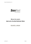
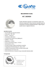
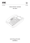
Technical manual for Multi Apartment Gateway 1456B
N0 POE
A4
Passion.Technology.Design.
Warnings
• Install the equipment by carefully following the instructions given by the manufacturer and in compliance with the standards in force.
• All the equipment must only be used for the purpose it was designed for. Comelit Group S.p.A. declines any responsibility for improper use of the apparatus, for any alterations made
by others for any reason or for the use of non-original accessories or materials.
• All the products comply with the requirements of Directive 2006/95/EC (which replaced Directive 73/23/EEC and subsequent amendments) as certified by the CE mark they carry.
• Do not route the riser wires in proximity to power supply cables (230/400V).
• Installation, mounting and assistance procedures for electrical devices must only be performed by specialised electricians.
• Cut off the power supply before carrying out any maintenance work.
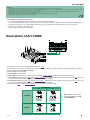
Article 1456B is a multi-apartment gateway that:
• can serve up to 200 apartments, with a maximum of 15 slave devices per apartment;
• can answer calls from a external unit via a virtual door entry monitor App for smart phone/tablet or using a normal GSM or landline telephone;
• incorporates the SIP protocol to enable telephone calls via SIP server or via virtual lines purchased from a SIP services provider;
• allows up to 4 simultaneous audio/video calls;
• can be configured remotely from a web page.
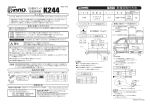
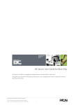
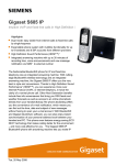
Description of Art.1456B
SOLO CON CAVO ROSSO COMELIT 2E7T000500
ONLY WITH COMELIT RED CABLE 2E7T000500
FIXED POE
A1
1
2
A2
SETTABLE POE
A3
N0 POE
A4
3
Art.1456B
4
5
6
7
8
9
1.
2.
3.
4.
5.
6.
7.
Ethernet port for ViP system riser input (default addressing: Autoip).
Dip switches for the procedures "Reboot with predetermined network settings" on page 19 and "Restoring factory settings" on page 20.
Power supply input via Art. 1441, Art. 1441B.
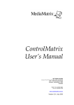
CV1 and CV2 for setting port A2.
CV3 and CV4 for setting port A3.
A4 non POE Ethernet port for PC or router connection (default: Static IP address 192.168.1.200, netmask 255.255.255.0).
A3 non POE settable Ethernet port POE (default: Static IP address 192.168.1.200, netmask 255.255.255.0). Set the port as POE if you want
to connect devices that require a power supply (door entry monitors, for example).
8. A2 non POE settable Ethernet port POE (default: Static IP address 192.168.1.200, netmask 255.255.255.0). Set the port as POE if you want
to connect devices that require a power supply (door entry monitors, for example).
9. A1 Ethernet port POE (default: Static IP address 192.168.1.200, netmask 255.255.255.0).
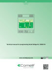
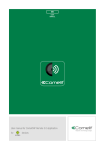
SETTABLE POE
CV1 CV2
A2
CV3CV1
CV4CV2
CV3 CV4
CV1 CV2
CV3CV1
CV4CV2
CV3 CV4
POE
A3
POE
SETTABLE
DO NOT USE
STANDARD
ETHERNET*
DO NOT USE
STANDARD
ETHERNET*
CV1 CV2
DEFAULT
CV1 CV2
STANDARD
ETHERNET
< BACK
CV3CV1
CV4CV2
NON POE
*
Only connect to the router
or PC using the red Comelit
cable 2E7T000500
CV3 CV4
NON POE
CV3CV1
CV4CV2
CV3 CV4
STANDARD
ETHERNET
2
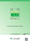
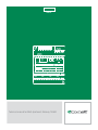
Configuration of Art.1456B
√√ This operation requires a PC loaded with the software ViP Manager version 2.3.0 or later (downloadable from the website www.
comelitgroup.com).
√√ An active internet connection is also required.
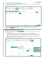
1) Connection
Article1456B has 2 network interfaces, A and B, labelled for easy identification, which can be configured separately to meet different system
requirements. Depending on the type of system, connect the devices as shown in the following figures:
VIP NETWORK + INTERNET CONNECTION NETWORK
SYSTEM WITH SINGLE NETWORK
ViP SYSTEM
Art.1441
Art.1441B
+ -
B
40-56 Vdc
Artt.1456B
A1
A2
SETTABLE POE
A3
IP ADDRESS AUTOIP
NON POE
A4
STATIC IP ADDRESS
192.168.1.200 (default)
+ -
B
40-56 Vdc
Artt.1456B
INTERFACE A
ONLY WITH COMELIT RED CABLE 2E7T000500
ONLY WITH COMELIT RED CABLE 2E7T000500
FIXED POE
INTERFACE B
INTERFACE A
ONLY WITH COMELIT RED CABLE 2E7T000500
ONLY WITH COMELIT RED CABLE 2E7T000500
FIXED POE
A1
A2
SETTABLE POE
A3
NON POE
A4
STATIC IP ADDRESS
192.168.1.200 (default)
ViP SYSTEM
ROUTER
with active
internet connection
Installer PC
with ViP Manager
version 2.3.0 and higher
Take particular care with regard to the network
interface settings and do not configure interfaces A
and B with the same addresses or similar parameters:
each IP address must be unequivocal, the addresses
of the interfaces A and B must not belong to the same
subnet.
< BACK
ROUTER
with active
internet connection
Installer PC
with ViP Manager
version 2.3.0 and higher
All system devices form part of a single network, so it it is
only necessary to configure interface A.
In this case, DO NOT alter the configuration of interface B.
3
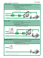
2) ViP Manager addressing
CASE 1
CASE 2
efault address of the device (192.168.1.200) belonging to the
d
same router network (e.g.: 192.168.1.1)
efault address of the device (192.168.1.200) NOT belonging
d
to the same router network (e.g.: 192.168.0.1)
t.
Art.1456B
t.
Art.1456B
INTERFACE A
ONLY WITH COMELIT RED CABLE 2E7T000500
ONLY WITH COMELIT RED CABLE 2E7T000500
FIXED POE
A1
A2
SETTABLE POE
A3
NON POE
A4
STATIC IP ADDRESS
192.168.1.200 (default)
INTERFACE A
ONLY WITH COMELIT RED CABLE 2E7T000500
ONLY WITH COMELIT RED CABLE 2E7T000500
FIXED POE
A1
A2
...
...
SETTABLE POE
A3
NON POE
STATIC IP ADDRESS
192.168.1.200 (default)
A4
192.168.1.X
...
...
192.168.0.X
ROUTER
ROUTER
192.168.1.1
192.168.0.1
Installer PC
Installer PC
interface A must be assigned
a new Static IP address belonging to the same
network as the devices connected to interface A
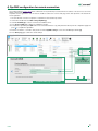
CASE 1
OBSERVE THE FOLLOWING PROCEDURE IN CASE 1
PERFORM A DHCP SYSTEM SCAN AND ASSIGN A VIP ADDRESS
Follow the procedure below to perform a system scan in DHCP, to locate all the devices connected to interfaces A and B:
• an IP address will be automatically assigned to the devices in addressing mode Autoip (connected to interface B);
• an IP address will be automatically assigned to the devices in addressing mode DHCP (connected to interface B), if the system
is connected to a server with the DHCP function active;
• devices with Static IP address will be identified only if they have a network address that is compatible with that of interface A.
1. From Options [a] / Local connections [b] tick DHCP Enable [c] and confirm [d].
a
b
During the system scan...
SYSTEM
SCAN
IN DHCP
AN IP COMPATIBLE
WITH THE SYSTEM
WILL BE ASSIGNED
TO THE PC
E.G. 192.168.1.30
c
d
Installer PC
< BACK
4
CASE 1
2. Launch the system scan by pressing Scan System [e].
»» all the devices connected to the system will be displayed in the device list.
3. Select device 1456 B [f], select Addressing/ViP address [g], assign an unequivocal ViP address to the device [h] and press Write
page [i] to save the current settings.
e
f
h
g
i
In the case of a system with 2 1456B devices, it will be necessary to assign to interface A of one of the two devices
a new Static IP address (as described in "case 2"), as each device must have a unequivocal IP address.
CASE 2
OBSERVE THE FOLLOWING PROCEDURE IN CASE 2
ASSIGN TO INTERFACE “A” A NEW Static IP address
The following procedure describes how to assign network settings to the device1456B that are compatible with those of the devices
connected to interface A.
1. Open the software ViP Manager version 2.3.0 or later (downloadable from the website www.comelitgroup.com).
2. From Options [a] / Local connections [b] untick the DHCP enable box and assign an IP address to your PC [c] (in the
example: 192.168.1.2)* that belongs to the same network as the IP address of interface A (default=192.168.1.200) and confirm
[d].
*the last value must be within the range of 2 to 253 excluding: 200 (assigned to the gateway Art. 1456B) and the values
already assigned to other devices connected to the network.
a
b
Assign to the PC an
IP address that is
compatible with the
network of the 1456B
(e.g.: 192.168.1.2) so that
the two devices are able
to communicate
c
d
< BACK
5
CASE 2
3. Launch the system scan by pressing Scan System [e]
»» the 1456B will appear in the device list [f]
4. In Addressing/ IP address [g] assign device 1456B a Static IP address [h] and a IP netmask [i] compatible with the system
for example IP: 192.168.0.5, netmask: 255.255.255.0 (warning: the IP address must not already be in use).
5. Enable "Use default gateway" [l] ONLY for the interface connected to the router (interface A by default)
6. Set the gateway address[m] , for example 192.168.0.1 press Write page [n] to save the current settings.
e
f
g
h
i
m
Assign to device 1456
network settings that
are compatible with
those of the devices
connected to interface
A so that they can
communicate.
Enable "Use default l
gateway" ONLY for the
interface connected to
the router (interface A
by default)
n
»» device 1456B will now be in the same network as the router (192.168.0.X)
t.
Art.1456B
INTERFACE A
ONLY WITH COMELIT RED CABLE 2E7T000500
ONLY WITH COMELIT RED CABLE 2E7T000500
FIXED POE
A1
A2
SETTABLE POE
A3
NON POE
A4
STATIC IP ADDRESS
192,168.0.5
192.168.0.X
...
...
ROUTER
192.168.0.1
Installer PC
In the cases of "ViP Network + Internet connection network" systems, take particular care with regard to the
network interface settings and do not configure interfaces A and B with the same addresses or similar parameters:
each IP address must be unequivocal, the addresses of the interfaces A and B must not belong to the same subnet.
< BACK
6
CASE 2
PERFORM A DHCP SYSTEM SCAN AND ASSIGN A VIP ADDRESS
Follow the procedure below to perform a system scan in DHCP, to locate all the devices connected to interfaces A and B:
• an IP address will be automatically assigned to the devices in addressing mode Autoip (connected to interface B);
• an IP address will be automatically assigned to the devices in addressing mode DHCP (connected to interface A), if the system
is connected to a server with the DHCP function active;
• devices with a static address will be identified only if they have a network address that is compatible with that of interface A.
1. From Options [a] / Local connections [b] tick DHCP Enable [c] and confirm [d].
a
b
During the system scan...
SYSTEM
SCAN
IN DHCP
c
AN IP COMPATIBLE
WITH THE SYSTEM
WILL BE ASSIGNED
TO THE PC
E.G. 192.168.0.30
d
Installer PC
2. Launch the system scan by pressing Scan System [e].
»» all the devices connected to the system will be displayed in the device list.
3. Select the device 1456 B [f], select Addressing/ViP address [g], assign an unequivocal ViP address to the device [h] and press
Write page [i] to save the current settings.
e
f
h
g
i
< BACK
7
3) Licence activation:
Activation of the licenses for each apartment allows the users of that residential unit to use the special functions provided by the device 1456B
(see page 9 for further information about licenses):
• remotely answer an audio/video call from an external unit using a smartphone or tablet (master and slave license);
• answer an audio call from a GSM or landline telephone (all licenses);
• perform an audio telephone backup of an unreachable device (master and slave license);
• the possibility to dispense with a master internal unit (master license).
√√ An active internet connection is required to complete the license activation procedure.
√√ A license is needed for each apartment that wishes to make use of the functions described above.
1.
2.
3.
4.
Select device 1456B [a].
Press Add license [b].
Press Add license file/s [c].
Look for license files with the extension .viplcs [d] on the USB storage device (if supplied at time of purchase) or from the folder where
it was saved when purchased and confirm by pressing Open [e].
»» a new line with the newly installed licenses will appear in the license activation wizard window.
5. Repeat steps 3 and 4 to install other licences.
6. Press Next [f],
7. enter a valid email address, press Next and confirm.
b
a
Open
Search
d
recent
documents
Desktop
Documents
c
you can select more than
one file at a time
f
Computer
resources
Network resources
Filename:
Open
File type:
Cancel
e
»» In main settings/Licenses [g] you can view all the licenses installed[h].
h
g
< BACK
8
LICENSES AVAILABLE FOR PURCHASE
MASTER LICENSE:
• Master door entry monitor not required (already integrated in the 1456B)
• Up to 15 slaves devices can be added for each apartment, including:
• Smartphone / Tablet + Comelit App
• PSTN/GSM telephone
• Door entry monitor (configured as slave)
EXAMPLE APARTMENT WITH MASTER LICENSE:
AUDIO TELEPHONE BACKUP
VIP *
NO
APP ACTIVE AND
NETWORK DATA
AVAILABLE?
INTERNET
APP
GSM
YES
PSTN
SIP PROVIDER
* it is possible to add ViP internal units in Slave mode
SLAVE LICENSE:
• A master door entry monitor is required
• Up to 15 slaves devices can be added for each apartment, including:
• Smartphone / Tablet + Comelit App
• PSTN/GSM telephone
• Additional door entry monitors (configured as slaves)
EXAMPLE APARTMENT WITH SLAVE LICENSE:
AUDIO TELEPHONE BACKUP
VIP *
NO
APP ACTIVE AND
NETWORK DATA
AVAILABLE?
INTERNET
APP
GSM
YES
PSTN
SIP PROVIDER
* it is possible to add ViP internal units in Slave mode
TELEPHONE LICENSE:
• Master door entry monitor not required (already integrated in the 1456B)
• Up to 15 slaves devices can be added for each apartment, including:
• PSTN/GSM telephone
• Door entry monitor (configured as slave)
EXAMPLE APARTMENT WITH TELEPHONE LICENSE:
VIP *
SLAVE DOOR ENTRY MONITOR
(OPTIONAL)
GSM
PSTN
SIP PROVIDER
* it is possible to add ViP internal units in Slave mode
< BACK
9
4) DynDNS configuration for remote connection
The DynDNS address (Dynamic DNS) allows a DNS name to be permanently associated with the IP address of the same host, even if that
address subsequently changes.
A DynDNS must be registered in order to make the 1456B accessible from a remote web page and to allow operation of the Comelit ViP
remote application.
√√ An active internet connection is required to complete the license activation procedure.
1.
2.
3.
4.
Select article 1456B and select Main Settings/DynDNS [a].
Select ComelitDNS [b] in order to use the free ComelitDNS service .
Press Register CDNS [c] to register a ComelitDNS hostname.
Complete the registration panel (NB: make a note of the data entered or copy and paste them directly into the configuration page) and
press
to complete the registration.
5. Enter the "hostname", "user name" and "password" in the "DynDNS settings" screen of the ViP Manager software [d].
6. Press Write page [e] to confirm the current settings.
b
d
a
write the complete host
name, for example:
nome_host3.comelitdns.com
c
e
Comelit DNS registration form
< BACK
10
5) Port Forwarding setting for remote connection
Port forwarding is the operation that allows the transfer of data from one device to another via a specific communication port. This procedure
enables an external user (mobile phone) to access a device on a local network (1456B).
The procedure for opening router ports for the article 1456B is required in order to allow remote access to the system via a web page (port
TCP 8080) and via an App (port TCP 64100*, port UDP 64100*).
* For some internet service providers, port 64100 is not available. In this case, try changing the address of the port with one of
the following: 25, 80, 110, 143 or call your internet service provider.
√√ With the PC still connected by Ethernet cable to article 1456B (see page 3).
1. Access the browser and enter the IP address of the router in the navigation bar, for example: 192.168.1.1
2. Log in by entering the username and password (these can be found in the router user manual).
The port configuration method may differ according to the brand and type of router used
3. Look for the sections "Port Opening" or "Apps and games" or "Port Forwarding" (if not displayed on the main menu, search for them in
Advanced settings) and add the ports you wish to configure.
4. Fill in the configuration panel (see example in the figure below):
a. Enter a name.
b. Select the desired protocol (for example: TCP for the port 8080, TCP/UDP for the port 64100).
c. For the external port, enter the desired value (e.g. 8080 / 64100); enter the same value in the Starting and Ending fields to open a single port.
d. For the internal port, enter the desired value (8080 / 64100); enter the same value in Starting and Ending fields to open a single port.
e. Enter the IP address of the ViP gateway, for example (default= 192.168.1.200).
f. Confirm.
5. Repeat the procedure for each port you wish to open.
< BACK
11
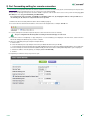
6) SIP settings configuration
The SIP settings configuration procedure is only to be used when you wish to channel a door entry phone communication to a SIP digital
telephone line (PSTN/GSM).
It is possible to purchase up to 15 SIP phone lines to be shared between all the apartments. Each phone line is a communication channel:
when a call is received from an external unit to landline or mobile phone, the first available SIP line is used.
√√ Purchase the desired number of SIP phone lines (max 15) from a SIP services provider: each phone line is a valid account
on the SIP server used to make telephone calls; the user settings and password are to be entered in the “SIP settings”
screen (see page. 13).
1. Select the device 1456B and select Main Settings/SIP settings [a].
2. Enter the IP address of the SIP service provider (for example: sip.messagenet.it) and the UDP port of the server supplied by the service
provider (for example: 5061) [b].
3. Leave the parameter "Codec preference" [c] ( for audio encoding/decoding) on the default setting: PCMA/PCMU.
US users only, select the codec PCMU.
4. Press Write page [d] to save the current settings.
b
c
a
d
DTMF open relay 1/2/3: sequence of keys to press (minimum 3, maximum 6) to send a command to activate the relay from a
telephone (the default values can be changed)
< BACK
12
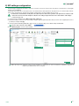
7) SIP phone lines configuration
Access to SIP phone lines is controlled by the username and password supplied by the SIP services provider at the time of purchase. Some
providers also provide a User ID (which can be variously designated "User authentication", "user auth" or "user ID". The procedure for phone
lines configuration is described below.
1. Select the device 1456B and select Main Settings/SIP phone lines [a].
2. For each SIP phone line purchased, enter the respective username and password [b].
3. For each SIP phone line purchased, enter the user ID [c] only if this has been provided by the SIP services provider, otherwise leave
the field blank.
4. Press Write page [d] to save the current settings.
c
b
a
If the username, the password and the user
ID supplied by the SIP services provider are
valid for more than one SIP phone line, reenter the username, password and user ID in
the subsequent rows for all the phone lines
purchased.
For example: if 5 SIP phone lines have been
purchased for which you have 1 username,
1 password and 1 user ID, enter the same
credentials in each of the first 5 rows.
d
A maximum of 15 SIP phone lines may be enabled.
The phone lines are shared between all the users of the system connected to the device 1456B and are managed on a
"first come, first served" basis.
< BACK
13
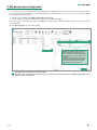
8) Apartments configuration
In the apartments configuration screen, each apartment can be assigned a license, a ViP address (unequivocal) and a description to allow
easy identification of the apartment and the user.
√√ An apartment can be enabled for each available license.
1. Select device 1456B and select Main Settings/DynDNS [a].
2. Configure the individual apartments (max 200) [b]:
• Enabling: enable/disable the license for the apartment by selecting Enabled/Disabled.
• License type: assign the type of license purchased for the apartment, choosing between Slave/Master/Telephone.
• ViP address: enter an unequivocal ViP address to identify the apartment.
• Description: enter a description to identify the apartment.
3. Press Write page [c] to save the current settings.
b
a
c
< BACK
14
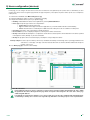
9) Users configuration (devices)
In this page you can configure the slave devices that can be activated for each apartment (max. 15) Each device is identified by its slave
number. Each device must be assigned a type (internal unit, app or telephone), a description, the phone number (in the case of a telephone/
mobile phone).
1. Select device 1456B and select Main Settings/Users [a].
2. Select the apartment for which you wish to configure the users [b]
3. Configure the individual devices (max 15 per apartment) [c]:
• Enabling: enable/disable the device for the apartment by selecting Enabled/Disabled.
• Device type: assign the type of device choosing between:
• Internal unit: Comelit ViP internal unit;
• App: ComelitViP Remote App for Android or Apple devices (consult the relative manual for further details);
• Phone: virtual ViP device controlled by the 1456B and used to make phone calls to a landline or mobile phone.
• Description: Description: enter a description to identify the device.
• Phone number: if you are configuring a telephone, enter the phone number of the device.
• Backup: enable/disable the backup line to configure the current device as a backup unit to which failed calls to the device specified
in the adjacent column ("Backup of") are to be forwarded.
• Backup of: specify the device to be backed up by selecting the corresponding slave device.
Backup example: the slave 3 phone number (John Phone) is enabled as the backup unit of the App slave 1 (John App) installed on the
same device --> If the App "John App" cannot be reached, after a few seconds the call will be redirected to the phone
number "John Phone".
4. Press Write page [d] to save the current settings.
b
c
a
d
Slave ID of the device
Each apartment supports 15 devices, which are assigned a device ID (slave number) that identifies the device within
the apartment. The device ID assigned in this page must correspond to that assigned to the same device in the page
"Addressing/ViP address".
It is advisable to assign the slave numbers 1-2-3 to devices that can receive the video signal( internal units/applications),
so that during a call they can receive the video signal directly, without the user having to press a video request button.
< BACK
15
10) Message server configuration
The following procedure describes how to specify on the art. 1456B the IP or ViP address of the art. 1952 device to be used as a message
server (if present)
1. Select device 1456B and select Main Settings/Message server [a].
2. From the pull-down menu [b] select ViP address or IP address and enter the address of the CPS device that is to be used as a message
server.
3. Press Write page [c] to save the current settings..
b
a
c
< BACK
16
Special configurations
App connection settings
From the following configuration page you can:
• set personalised parameters for the app connection (for example, if you wish to set a different port for connection of the app or if there is
a static public address you wish to use for remote connection.
•change the maximum number of video connections on the network (max. 16) or on the App (max. 4).
1. Select the device 1456B and select Main Settings/App connection settings [a].
2. Edit the values you wish to personalise.
App connection settings
• Local address: leave the field empty if you wish to set as the local address the address of interface A, as specified in the page
Addressing/IP address.
• Local/remote TCP/UDP port (default 64100): for some internet service providers, port 64100 is not available: if the ComelitViP
Remote App fails to register, try changing the address of the port with one of the
following: 25, 80, 110, 143 (open the respective ports on the router, see page
11 and edit the values on the ComelitViP Remote App).
• Remote address: leave the field empty if you wish to set as the remote address the hostname registered during configuration of
the DynDNS settings. If necessary, you can assign a static public address for remote connection.
Video connections
• Maximum video connections on net: maximum number of simultaneous video connections on the network (max. 16).
• Maximum video connections on tunnel (App): maximum number of simultaneous video connections on the App (max. 4).
3. Press Write page [b] to save the current settings.
a
if necessary, you can
assign a static public
address
for
remote
connection.
b
< BACK
17
Connection to the configuration web pages
From the web pages you can perform all of the operations available on ViP Manager except license activation.
The backup and restore function is only available on the web pages.
1A) Remote connection
1B) Local connection
√√ Once the DynDNS configuration has been completed (see
page 10) and port 8080 (see page 11) on the router has
been opened, remote access of the device will be possible.
√√ AN active internet connection is also required.
1A.Enter the registered hostname or the public IP address, as in
the following examples, and press enter.
http://
registered hostname.comelitdns.com
example = nome_host3.comelitdns.com
:8080
√√ With the PC connected via Ethernet cable to interface A of
art. 1456Ba and IP address belonging to the same network
as interface A.
1B.Enter the IP address of interface A as in the following
example, and press enter.
http://
Interface A IP address
default = 192.168.1.200
:8080
or:
http://
public IP
example = 213.149.219.88
:8080
2) Login
1. Press Login [a]
2. Enter the installer password (default= comelit) and conform by pressing Login [b]
a
< BACK
b
18
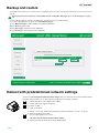
Backup and restore
The backup function allows you to save the current configuration, which can then be subsequently called up at any time using the restore
function.
The backup and restore functions are only available from the configuration web pages (to access the web pages, see page
18)
1. As described on page 18: connect to the web pages of the device (in local or remote) and log in.
2. Access the Backup/Restore section by pressing Backup/Restore [a]
3. Press Make Backup [b] to create a backup of the current configuration.
4a.Press Restore [c] and confirm.
5a.Press Reboot [d] to activate the saved configuration.
4b. Press Delete [e] to cancel backup of the configuration.
a
e
c
b
d
Reboot with predetermined network settings
The function reboot with predetermined network settings allows you restart the device with the default network
parameter settings (interface A= 192.168.1.200), while keeping the other settings unchanged.
OFF
ON
√√ With the dip switches in the default positions (OFF).
1. Switch off the power supply to the device.
OFF
ON
2. Set DIP 1 to ON
3. Power on the device.
4. Wait 20 - 40 seconds, until the LEDs start flashing slowly and alternately (1 sec red / 1 sec green).
OFF
ON
5. Return all the dip switches to OFF.
»» The green LED will flash for 5 seconds.
»» The device will start with the default network settings.
6. At the next restart, the device will recover the saved settings.
< BACK
19
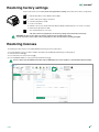
Restoring factory settings
This procedure allows you to restore all the factory parameter settings and to delete all the device configurations.
OFF
ON
√√ With the dip switches in the default positions (OFF).
1. Switch off the power supply to the device.
OFF
ON
2. Set all the dip switches to ON.
3. Power on the device.
4. Wait 20 - 40 seconds, until the LEDs start flashing rapidly and alternately (0.1 sec red / 0.1 sec green).
OFF
ON
5. Return all the dip switches to OFF.
»» The red LED will flash for 5 seconds.
»» The device will reset all parameters to the factory settings and restart in the normal way.
WARNING: the full reset procedure also deletes and the licenses installed on the device
You can restore the licenses (max. 2 times) using the procedure described in the following paragraph.
Restoring licenses
The following procedure allows you to restore licenses lost during the full reset procedure:
1.
2.
3.
4.
From ViP Manager, look for the device 1456B as described in the ViP Manager addressing procedure (page 4).
Select the device 1456B [a].
Press "Add license" from the main menu [b].
Press "Load from server" to restore previously activated licenses [c].
Licenses can be restored a maximum of two times only. For additional license restore operations, contact Comelit technical assistance.
b
a
c
< BACK
20
C
N
1
C
F
P
0 S
V +
C
N
1
S S
+
C
N
1
S 0
1 + V
OUT IN
1
0
V
P
A
N
C
F
P
G
C
N AL F
D
P
C
N
3
-
OP OP S
+ - +
C
F
P
P
A
N
AL
P
A
N
6304
0
V
6202W+
6231
OP OP 0 OUT AL
+ - V 1
6203W
0 AL OUT 0
V
1 V
IN IN
1 2
-
1
2
3
S 0
1 + V
OUT IN
OUT OUT OUT OUT
4
1
0
V
P
A
N
C
F
P
C
N
1
C
F
P
0 S
V +
C
N
1
AL
P
A
N
6501
1
2
1440
+
VIP/016G
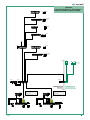
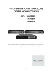
Connection diagram for ViP network +
Internet connection network system
6304
0
V
6202W+
6231
OP OP 0 OUT AL
+ - V 1
ROUTER
192.168.1.1
1441
L
N
1440
-
+
V V
1456B
+
-
IN IN
1 2
OUT OUT OUT OUT
1
2
3
+
4
-
B
A
1
A
2
A
3
A
4
100-240 V
INTERFACE B
AUTO IP
1595
-
+
ORANGE WIRE
TX -
WHITE/ORANGE WIRE
TX +
GREEN WIRE
RX -
WHITE/GREEN WIRE
RX +
1595
-
+
120-230 V
S
E
< BACK
C
O
M
NC NO
G
N
D
R
T
E
ORANGE WIRE
TX -
WHITE/ORANGE WIRE
TX +
GREEN WIRE
RX -
WHITE/GREEN WIRE
RX +
INTERFACE A
IP: 192.168.1.X
120-230 V
V V TX TX RX RX
+ - + - +
-
4682C
J1
J1
J2
33436
S
E
C
O
M
NC NO
G
N
D
R
T
E
V V TX TX RX RX
+ - + - +
-
4682C
J1
J2
P
R
G
G
N
D
485 485
D- D+
S
24 24
Vac Vac
J1
J2
3360A
21
C
N
1
C
F
P
0 S
V +
C
N
1
S S
+
C
N
1
S 0
1 + V
OUT IN
1
0
V
P
A
N
C
F
P
G
C
N AL F
D
P
C
N
3
-
OP OP S
+ - +
C
F
P
P
A
N
AL
P
A
N
6202W+
6231
OP OP 0 OUT AL
+ - V 1
6203W
0 AL OUT 0
V
1 V
IN IN
1 2
-
1
2
3
S 0
1 + V
OUT IN
OUT OUT OUT OUT
4
1
0
V
P
A
N
C
F
P
C
N
1
C
F
P
0 S
V +
C
N
1
AL
P
A
N
6501
1
2
1440
+
VIP/016GS
Connection diagram for Single network
system
6304
0
V
6304
0
V
6202W+
6231
OP OP 0 OUT AL
+ - V 1
ROUTER
192.168.1.1
INTERFACE A
IP: 192.168.1.X
1441
L
1441
1440
N
-
+
V V
+
-
IN IN
1 2
OUT OUT OUT OUT
1
2
3
L
4
100-240 V
-
+
V V
+
-
B
A
1
A
A
2
3
A
4
100-240 V
1595
-
+
ORANGE WIRE
TX -
WHITE/ORANGE WIRE
TX +
GREEN WIRE
RX -
WHITE/GREEN WIRE
RX +
1595
-
+
120-230 V
S
E
C
O
M
NC NO
G
N
D
R
T
E
ORANGE WIRE
TX -
WHITE/ORANGE WIRE
TX +
GREEN WIRE
RX -
WHITE/GREEN WIRE
RX +
120-230 V
V V TX TX RX RX
+ - + - +
-
4682C
< BACK
1456B
N
J1
J1
J2
33436
S
E
C
O
M
NC NO
G
N
D
R
T
E
V V TX TX RX RX
+ - + - +
-
4682C
J1
J2
P
R
G
G
N
D
485 485
D- D+
S
24 24
Vac Vac
J1
J2
3360A
22
Glossary*
• Autoip: Automatic Private IP Addressing (known as APIPA or Auto IP), is a method for automatically assigning IP addresses to the devices
connected to the network.
• Dynamic DNS: Dynamic DNS is a technology that allows a DNS name to be permanently associated with the IP address of the same host,
even if that address subsequently changes.
• DHCP: In telecommunications and information technology, Dynamic Host Configuration Protocol (DHCP) is an application layer network
protocol that enables the devices or terminals of a local network to automatically receive on each request to an IP network i.e. the internet)
the necessary IP configuration to establish a connection and operate on a wider network based on Internet Protocol, i.e. to interact with all
the other subnets, exchanging data, provided that they are also integrated in the same way with the IP protocol.
• Gateway: a gateway is a network device that operates at network level and above of the ISO/OSI model. It's main function is to transport
network data packets outside a local network (LAN) Gateway is a generic term for a service that sends data packets outside of the network;
the hardware device that fulfils this task is usually a router. Simpler networks have just one gateway that sends all outbound traffic to the
Internet network. More complex networks have several subnets, each of which refers to a gateway which routes data traffic to other subnets
or redirects it to other gateways.
• Dynamic IP address: dynamic addresses are used to identify non-permanent devices in a LAN. A server in the LAN automatically dynamically
assigns the address, selecting it a random from a preset range. You can select the range of addresses in accordance with the number of
users by setting the netmask, i.e. by telling the DHCP server how many address bits can be assigned dynamically to each single client that
accesses it. For example, if the netmask has the value 255.255.255.0 (where each block of numbers separated by a point denotes a group
of 8 bits), only the last 8 bits can be assigned to the hosts.
• Static IP address: static addresses are used to identify semi-permanent devices with a permanent IP address. Network servers, printers,
etc. typically use this addressing method. Static addressing is generally used in preference to dynamic addressing for non permanent
network devices if there is a limited number of hosts in the subnet and/or for security reasons, so that the actions of each host and the relative
user can be kept under control.
• Public IP address: in telecommunications and information technology a public IP address is an IP address in the address range of the
internet network that is unequivocally allocated and is potentially accessible from any other public IP address, and therefore can be used
for addressing and routing via IP protocol.
• POE: Power over Ethernet or PoE (the acronym) is a technique for powering equipment via the same cable as that used for Ethernet
connection. It is very useful when there is no convenient electrical power source near the termination or when you wish to reduce the number
of elements and wires; for example, an IP phone on a desk can be powered directly via the Ethernet cable in Power over Ethernet, thereby
eliminating the need for a power supplier and its cable, making for a simpler, less cluttered installation. For the moment, these techniques
are used mainly to power devices that consume only a little power, such as VoIP telephones, access points and webcams.
• Port forwarding: in computer networks, port forwarding is the operation that allows the transfer of data from one device to another via a
specific communication port.. This technique can be used to allow an external user to reach a host with a private IP address (within a LAN)
via a port of the corresponding public IP address. This operation requires a router capable of automatic translation of network addresses,
or NAT.
*Sources
Dynamic DNS. (2015, June 8). Wikipedia, L'enciclopedia libera. http://it.wikipedia.org/wiki/Dynamic_DNS
Dynamic Host Configuration Protocol. (2015, June 8). Wikipedia, L'enciclopedia libera. http://it.wikipedia.org/wiki/Dynamic_Host_Configuration_Protocol
Gateway (information technology). (2015, June 8). Wikipedia, L'enciclopedia libera. http://it.wikipedia.org/wiki/Gateway_(informatica)
IP Address. (2015, June 8). Wikipedia, L'enciclopedia libera. http://it.wikipedia.org/wiki/Indirizzo_IP
Public IP address (2015, June 8). Wikipedia, L'enciclopedia libera. http://it.wikipedia.org/wiki/Indirizzo_IP_pubblico
Power over Ethernet (2015, June 8). Wikipedia, L'enciclopedia libera. http://it.wikipedia.org/wiki/Power_over_Ethernet
Port forwarding. (2015, June 8). Wikipedia, L'enciclopedia libera. http://it.wikipedia.org/wiki/Port_forwarding
The contents of this page sourced from Wikipedia are distributed through licenza Creative Commons Attribuzione - Condividi allo stesso modo 3.0
The brands and commercial names appearing in this publication remain the property of their respective owners.
< BACK
23
1st edition 07/2015
code 2G40001422
w w w.comelitgroup.com
Passion.Technology.Design.