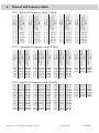
1
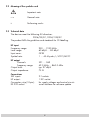
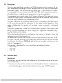
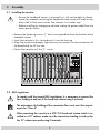
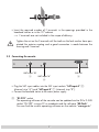
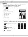
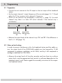
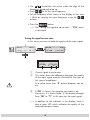
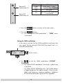
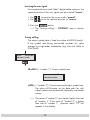
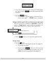
Head-End Digital Modulator
KLASSE
HDM 500 C
A
CLASS
CLASS
English
Assembly Instructions
Grundig SAT SystEms
GSS
Grundig SAT Systems GmbH
Beuthener Straße 43
D-90471 Nuremberg
Phone:
Fax:
E-mail:
Internet:
+49 (0) 911 / 703 8877
+49 (0) 911 / 703 9210
[email protected]
http://www.gss.tv
Contents
1 Safety regulations .....................................................................................................3
2 General information .................................................................................................3
2.1 Packing contents .......................................................................................3
2.2 Meaning of the symbols used .....................................................................4
2.3 Technical data ..........................................................................................4
2.4 Description ...............................................................................................5
2.5 Software query .........................................................................................5
3 Assembly .................................................................................................................6
3.1 Installing the cassette .................................................................................6
3.2 EMC regulations .......................................................................................6
3.3 Connecting the cassette .............................................................................7
4 The control panel at a glance ....................................................................................8
4.1 Menu items ..............................................................................................8
4.2 Functions of the control panel buttons ..........................................................8
5 Programming ...........................................................................................................9
5.1 Preparation ..............................................................................................9
5.2
Notes on level setting ................................................................................9
5.3 Programming procedure ..........................................................................10
5.4 Programming the cassette ........................................................................12
Selecting the cassette ...............................................................................12
Selecting the channel strip ........................................................................13
Selecting channel / frequency setting ........................................................13
Setting the output channel ........................................................................14
Setting the output frequency .....................................................................15
Switching the modulator off or on .............................................................15
Adjusting the output levels of the channel strips ...........................................15
Setting the LNB oscillator frequency ...........................................................16
Setting the input symbol rate .....................................................................17
Setting the input frequency .......................................................................17
Testing the signal to noise ratio .................................................................18
Setting the QAM modulation ...................................................................19
Inverting the user signal ...........................................................................20
Testing stuffing ........................................................................................20
Setting a substitute signal in the case of an incorrect input signal .................21
Saving settings........................................................................................21
6 Channel and frequency tables .................................................................................22
-2-
1
Safety regulations
Caution
• Assembly, installation and servicing should be carried out by authorised
electricians.
• Switch off the operating voltage of the system before beginning with assembly
or service work or pull out the mains plug.
• Do not perform installation and service work during thunderstorms.
• Install the system so it will not be able to vibrate…
- in a dust-free, dry environment
- in such a manner that it is protected from moisture, fumes, splashing water and
dampness
- somewhere protected from direct sunlight
- not within the immediate vicinity of heat sources
- in an ambient temperature of -20 °C to +50 °C.
• Ensure that the head-end station is adequately ventilated.
Do not cover the ventilation slots.
• Beware of short circuits
• No liability is accepted for any damage caused by faulty connections or inappropriate handling.
• Observe the relevant standards, regulations and guidelines on the installation and
operation of antenna systems.
• Earth the SAT receiver in accordance with DIN EN 50083-1 / EN 60728-11
and VDE 0855 (earthed, equipotential bonding rail).
• For further information please read the assembly instructions for the headend station used.
Take action to prevent static discharge when working on the device.
2
General information
2.1 Packing contents
1
2
1
1
cassette HDM 500 C
HF cables
CD (assembly instructions)
Brief assembly instructions
-3-
2.2 Meaning of the symbols used
Important note
—>
General note
•
Performing works
2.3 Technical data
The devices meet the following EU directives:
2006/95/EC, 2004/108/EC
The product fulfils the guidelines and standards for CE labelling.
HF input
Frequency range:
Level range:
Input norm:
Symbol rate:
950 … 2150 MHz
60 dBµV … 80 dBµV
QPSK
1 … 45 Msymb./s, SCPC/MCPC
HF output
Channels:
Frequency range:
Output level:
Output impedance:
S21 … C69
42.0 MHz … 860.0 MHz
typ. 97 dBµV
75 Ω
Connections
SAT inputs:
HF output:
Connection strip (10-pin):
RS 232 socket:
2 F sockets
1 IEC socket
for supply voltages and control circuits
serial interface for software update
-4-
2.4 Description
The twin transmodulator cassette is a QPSK-converter, which converts all stations modulated according to DVB-S standard and QPSK into two QAM-modulated cable signals. The cassette has two digital SAT IF inputs and an HF output.
It is equipped with two channel strips (“A” and “B”). Each channel strip consists
of a digital tuner, a digital signal preparation unit and a modulator.
The prepared input signals reach the HF output collector of the head-end station
via the HF output socket. The common output level of the channel strips can be
set at the output collector of the head-end station.
Two LEDs indicate if the respective channel strip is switched on (LED illuminates)
or off, and also provide an indication of the signal quality based on their
colour. Additionally the quality of the data stream received is displayed
(“CN…”).
The output symbol rate is fixed to a value of 6900 kSymb/s. If the symbol rate
being transmitted exceeds this value change to a high-order modulation (e.g.
from 64 QAM to 256 QAM).
When the head-end station is switched on, the two-line LC display shows the
software version of the control unit.
To operate this cassette the software version of the control unit must be “V 37”
or higher. You can find the current operating software for the control unit and
the cassette, the software “BE-Flash” and the current assembly instructions on the
website “www.gss.tv”.
The cassette is designed for use in the following head-end stations:
– STC 1200
– STC 316
– STR 19-8
2.5 Software query
Control unit
If necessary, you can activate the indication of the software version of the control unit manually:
• Press any two keys on the control unit of the head-end station simultaneously
until the display goes dark and the software version, e.g. “V 37” appears.
-5-
3
Assembly
3.1 Installing the cassette
– Ensure the head-end station is mounted so it will not be able to vibrate.
Avoid, for example, mounting the head-end station onto a lift shaft or any
other wall or floor construction that vibrates in a similar way.
– Before installing or changing a cassette unplug the power cable from the
mains power socket.
• Remove the fastening screws 1 of an unoccupied slot from the bracket of the
head-end station.
• Insert the cassette in this slot and push it into the housing.
• Align the cassette and apply slight pressure to connect it to the connections of
the board and the HF bus bar.
• Fasten the cassette with the 1 screws.
ACHTUNG!
Vor dem Cassettenwechsel
unbedingt Netzstecker ziehen!
CASSETTE
CASSETTE
CASSETTE
CASSETTE
CASSETTE
CASSETTE
CASSETTE
CASSETTE
CASSETTE
CASSETTE
CASSETTE
CASSETTE
0°
MESSAUSGANG
CAUTION!
Before changing cassettes remove
mains plug!
A
3.2 EMC regulations
KLASSE
To comply with the current EMC regulations, it is necessary to connect the
lines leading in and out of the head-end station using F terminals.
A
CLASS
CLASS
The attenuation of shielding of the connection lines must meet the requirements for “Class A”.
When mounting the cassette in a STR 19-8 head-end station which is installed in a 19” cabinet, make sure the connections leading in and out for
the 19” cabinet are made using F terminals.
-6-
• Insert the required number of F terminals in the openings provided in the
head-end station or in the 19" cabinet.
—> F terminals are not included in the scope of delivery.
Tighten the nut on the F terminal until the teeth on the lock washer have penetrated the exterior coating and a good connection is made between the
housing and F terminal.
3.3 Connecting the cassette
SAT input "B"
RS 232
SAT input "A"
• Plug the SAT input cables into the SAT input sockets “SAT input A”
(channel strip “A”) and “SAT input B” 1 (channel strip “B”).
• Connect the head-end station to the mains power supply.
3
2
“RS 232” socket
The operating software of the cassette can be updated via the 9-Pin D-SUB
socket “RS 232” using a PC or notebook and the software “BE-Flash”.
You can find the current operating software on the website “www.gss.tv”.
-7-
4
The control panel at a glance
4.1 Menu items
Program the cassette using the buttons on the control unit of the head-end station.
The two-line display of the control unit then shows the menus.
The parameters and functions to be set are underlined.
Use the
–
–
–
–
–
–
–
–
–
–
–
key to select the following main menu items:
Cassette
Channel strip
Channel / Frequency selection
Output channel / output frequency
Level setting
LNB oscillator frequency
Input symbol rate
Input frequency
QAM modulation
Stuffing
Substitute signal
BE–Remote
V 37
please wait . . .
4.2 Functions of the control panel buttons
The key pad on the head-end station is used to scroll through the menus and
menu items one at a time:
scrolls forward through the menus.
◀/▶
select parameters in the menus.
set values, initiate actions.
selects sub-menus.
AUDIO
M
scrolls backward through the menus.
saves entries.
-8-
5
Programming
5.1 Preparation
• Connect the test receiver to the HF output or the test output of the head-end
station.
• Set the output channel / output frequency of the cassette (page 14 / 15) and
adjust the TV test receiver to this channel / frequency.
• Switch on the channel strip (modulator) if necessary (s. page 15). For each
channel strip, there is a status LED which indicates if the channel strip is
switched on.
Status-LED
Status-LED
Channel strip Channel strip
"B"
"A"
• Balance the output levels of the channel strips “A” and “B” if the difference in
level is ≥ 1 dB (page 15).
5.2 Notes on level setting
In order to prevent interference within the head-end station and the cable system, the output level of the QPSK-QAM module must be lowered by 10 dB
compared to analogue modulators at 64 QAM, and by 4 dB compared to
analogue modulators at 256 QAM.
• Measure the output levels of the other cassettes and tune them to a uniform
output level using the appropriate level controls or software dependent on the
head-end station used. Please regard the assembly instructions of the respective head-end station.
-9-
5.3 Programming procedure
Ein / On
BE–Remote
V 37
please wait …
t > 10 s
Bx 1A
TWIN-SAT
C5-12,S3-24
C07
+
Box 4
V1
Bx 1A
TWIN-SAT
Böx 4
TWIN-SAT
Bx 5A
DVBT-DVBT
C5-12,S3-24
C07
C5-12,S3-24
C07
BD3
C09
QPSK-C
–––
Bx 4A
V1
Bx 4A
QPSK-C
OUTPUT
Channel
Bx 4A
S41
A/B
S41
Channel / Freq.
OUTPUT
on
◀/▶
on / off
Bx 4A
LEVEL
0 dB
0 … -10 dB
Bx 4A
LNB
◀/▶
10600 MHz
- 10 -
◀/▶
Bx 4A
27500
◀/▶
SYMBOL
DVB-S
Bx 4A
11836
-1.8
FREQ
Bx 4A
CN 12
12.0 dB
Bx 4A
4 … 256
QAM
64-QAM
Bx 4A
normal
C/N
(+ 9.6) OK
Anzeige: Signalqualität
Display: Signal quality
◀/▶
normal / inverse
STUFFING
SR=6900 (6325)
Bx 4A
FAILURE
Null Packets
Null Packets / Single Carrier
M
- 11 -
5.4 Programming the cassette
button for longer than 2 seconds cancels the pro—> Pressing the
gramming procedure. This takes you back to the program item “Selecting
the cassette” from any menu. Any entries that have not been saved are
reset to the previous settings.
—> Entries in the menus can be saved by pressing the M key. You are taken
back to the “Selecting the cassette” menu item.
• Switch on the head-end station
—> The display shows the software version (e.g. V 37)
—> The processor reads the cassettes‘ data
(approx. 10 seconds).
_
Ein / On
BE–Remote
V 37
please wait …
t > 10 s
Selecting the cassette
Bx 1A
TWIN-SAT
C5-12,S3-24
C07
+
Box 4
V1
Bx 1A
TWIN-SAT
Böx 4
TWIN-SAT
Bx 5A
DVBT-DVBT
C5-12,S3-24
C07
C5-12,S3-24
C07
BD3
C09
QPSK-C
–––
• Select the cassette you want to program (e.g. Box 4) by
repeatedly pressing the button
if necessary.
• By pressing the
- 12 -
button, activate channel strip “A”.
Selecting the channel strip
Bx 4A
V1
QPSK-C
A/B
S41
—> The display shows e.g. the menu “Bx 4A QPSK-C”:
“Bx”
stands for cassette (box),
“4”
for slot 4
“A”
for channel strip “A”
”QPSK-C”
Type of cassette
”S41”
Channel set
• By pressing
, select channel strip “A” or “B”.
• Press the
button.
—> The “Selecting channel / frequency setting” –
“OUTPUT” menu is activated.
Selecting channel / frequency setting
In this menu, you can choose the channel or frequency setting
for the adjustment of the HF output. The channel setting covers the range of channels S21 … C69, the frequency setting
covers the range from 42.0 MHz to 860.0 MHz.
The QAM signal is normally transmitted with a bandwidth of
8 MHz. This means that you can only use the channel centre
frequency of the existing channel raster in the range of channels S21 … C69 (frequency raster 8 MHz). The CCIR channel raster is 7 MHz in the range of the lower frequency bands
(channels C2 … S20). Therefore the frequency setting is used
here. If one uses the existing channel raster of 7 MHz in these
channel ranges, this will result in interference (overlapping)
with the 8 MHz QAM signal packages, thus causing transmission problems.
- 13 -
For programming in these channel ranges and in the frequency ranges below them, we recommend starting with channel
S21 / 306 MHz going back in steps of 8 MHz.
Bx 4A
OUTPUT
Channel
Channel / Freq.
to select channel setting “Channel” or frequen• Use
cy setting “Freq.”.
• Press the
button.
—> The “Setting the output channel” or “Setting the output frequency” – “OUTPUT” menu is activated.
—> If frequency setting is selected continue on page 15 with
“Setting the output frequency”.
Setting the output channel
In this menu you set the output channel (S21 … C69) of the
channel strip. Additionally the modulator of the channel strip
can be switched off or on (page 15).
Bx 4A
S41
OUTPUT
on
◀/▶
on / off
• Use the
buttons to set the output channel.
- 14 -
Setting the output frequency
In this menu you set the output frequency (42.0 … 860.0 MHz)
of the channel strip. Additionally the modulator of the channel
strip can be switched off or on.
◀/▶
Bx 4A
OUTPUT
466.00
on
◀/▶
on / off
• Use the ◀ / ▶ buttons to position the cursor under the digit
of the frequency displayed to be set then use
to set
the output frequency wished.
Switching the modulator off or on
• To switch off the modulator move the cursor under “on” using the ▶ button and then use the
buttons to switch
off “off” the modulator.
—> The switched off modulator is indicated by “ - - - ” in
the display.
• If the modulator is switched “off” use the
buttons to
switch it on “on”.
• Press the
button.
—> The “Adjusting the output levels of the channel strips”
– “Level” menu is activated.
Adjusting the output levels of the channel strips
In this menu you can set the output levels of the modulators of
the channel strips “A” and “B” to the same value.
Bx 4A
LEVEL
0 dB
0 … -10 dB
- 15 -
• Measure and note down the output level of the channel
strip.
• Save the settings by pressing the M button.
• Select the other channel strip (page 13), measure and note
down its output level.
• Activate the “LEVEL” menu of the channel strip with the
higher output level.
• By pressing
adjust the higher output level of one
channel strip to the lower output level of the other channel
strip incrementally from “0” to “–10 dB”.
• Press the
button.
—> The “Setting the LNB oscillator frequency” – “LNB”
menu is activated.
Setting the LNB oscillator frequency
Set the oscillator frequency of the LNB used in this menu.
Bx 4A
LNB
◀/▶
10600 MHz
• Use ◀ / ▶ to position the cursor under the digit to be set
for the frequency display.
• Press
to enter the oscillator frequency of the LNB
used.
• Press the
button.
—> The “Setting the input symbol rate” – “SYMBOL” menu
is activated.
- 16 -
Setting the input symbol rate
The symbol rates of the satellite transponders can be found in
the current channel table of the satellite operator, in various
satellite magazines and in the Internet.
◀/▶
Bx 4A
27500
SYMBOL
DVB-S
• Use ◀ / ▶ to position the cursor under the digit to be set
for the symbol rate displayed.
• Press
to enter the values of the symbol rate.
—> The “DVB-S” logo has no function.
• Press the
button.
—> The “Setting the input frequency” – “FREQ” menu is
activated.
Setting the input frequency
If three dots “ … “ appear in the second line of the display,
the cassette is in the “station search” mode. Please wait until
the process has finished.
Once the HF receiver has synchronised to the input signal,
any offset to the target frequency is displayed in MHz, e.g.
“– 1.8”.
If a question mark “?” appears in the second line of the display, there is no input signal present. Check the configuration
of the antenna system and head-end station as well as the
preceding settings of the cassette.
◀/▶
Bx 4A
11836
-1.8
FREQ
Bx 4A
CN 12
12.0 dB
- 17 -
C/N
(+ 9.6) OK
Anzeige: Signalqualität
Display: Signal quality
• Use ◀ / ▶ to position the cursor under the digit of the
frequency displayed to be set.
• Press
to set the input frequency.
• Set the frequency offset shown in the display to less than
1 MHz by varying the input frequency using the
buttons.
• Press the
button.
—> The “Testing the signal to noise ratio” – “C/N” menu
is activated.
Testing the signal to noise ratio
In this menu you can estimate the quality of the input signal.
◀/▶
Bx 4A
11836
-1.8
FREQ
Bx 4A
CN 12
12.0 dB
Bx 4A
12.0 dB
C/N
(+ 9.6) OK
Anzeige: Signalqualität
Display: Signal quality
C/N
(+ 9.6) OK
1
2
Current signal to noise ratio
This value shows the difference between the quality
of the input signal and the threshold of the tuner at
this type of modulation.
At a value lower than “5” picture dropouts can occur.
3
If “OK” is shown, the signal to noise ratio is ok.
If a value < 5 is shown under 2 the display changes
from “OK” to “??”. In this case test the input signal.
—> In addition to the indicator in the display, there is
also a status LED which indicates the quality of the
received transport stream:
- 18 -
Status LED
Channel strip "A"
LED indicator
Green
Yellow
Red
Off
Status LED
Channel strip "B"
• Press the
Indication
Signal quality is good
Signal quality is poor
No signal
The channel strip (modulator)
is switched off
button to return to the main menu.
• Press the
button.
—> The “Setting the QAM modulation” – “QAM” menu
is activated.
Setting the QAM modulation
In this menu, you can set the QAM modulation and invert the
user signal. For the setting of 256 QAM the output level is increased automatically.
Bx 4A
4 … 256
64-QAM
QAM
normal
◀/▶
normal / inverse
• Use
to set the QAM modulation (“4-QAM” …
“256-QAM”).
—> For higher QAM modulation, the output symbol rate
is lowered.
An output QAM modulation of > 64 QAM places
a large burden on the cable network. Due to noise,
delay and frequency response problems, reception
of the converted output signal can be impeded.
- 19 -
Inverting the user signal
For exceptional cases and “older” digital cable receivers, the
spectral position of the user signal can be inverted “inverse”.
• Use ◀ / ▶ to position the cursor under “normal”.
• Use
to set the spectral position to “inverse”.
• Press the
button.
—> The “Testing stuffing” – “STUFFING” menu is activated.
Testing stuffing
The output symbol rate is fixed to a value of 6900 kSymb/s.
If the symbol rate being transmitted exceeds this value
change to a high-order modulation (e.g. from 64 QAM to
256 QAM).
Bx 4A
STUFFING
SR=6900 (6325)
SR=6900 (= “number 1”): Output symbol rate
Bx 4A
STUFFING
SR=6900 (6325)
Number 1
Number 2
(6325) (= “number 2”): Current measured output symbol rate.
The value will fluctuate, as the data rates for individual stations are dynamically altered by the broadcasters.
—> The value of “number 2” must not be higher than that
of “number 1”. If the value of “number 2” is higher
than that of “number 1” , question marks “??” will
appear in the display.
- 20 -
Bx 4A
SR=6900
STUFFING
(6950) ??
• In this case you can return to the “Setting the QAM modulation” menu using the AUDIO button and increase the QAM
modulation.
• Press the
button.
—> The “Setting a substitute signal in the case of an incorrect input signal” – “FAILURE” menu is activated.
Setting a substitute signal in the case of an incorrect input signal
You use this menu to set whether a “Null Packets” QAM signal or a “Single Carrier” signal should be provided as an
output signal whenever an incorrect input signal occurs.
Bx 4A
FAILURE
Null Packets
Null Packets / Single Carrier
M
• Use the
buttons to set the output signal required.
Saving settings
• Press the M button.
—> Going back to “Selecting the cassette”
—> The settings are saved.
A (page 12).
—> By pressing the
button, you will be returned
to the menu item “Selecting the channel strip” via B
without saving the programmed data (page 13).
- 21 -
6
Channel and frequency tables
Kanal
Channel
Bildträgerfrequenz
Picture carrier frequency
[MHz]
Kanal
Channel
Bildträgerfrequenz
Picture carrier frequency
[MHz]
Kanal
Channel
Bildträgerfrequenz
Picture carrier frequency
[MHz]
Kanal
Channel
Bildträgerfrequenz
Picture carrier frequency
[MHz]
Kanal
Channel
Bildträgerfrequenz
Picture carrier frequency
[MHz]
CCIR – Band I/III (Frequency raster 7 MHz)
C
C
C
S
S
S
48.25
55.25
62.25
112.25
119.25
126.25
S
S
S
S
S
S
133.25
140.25
147.25
154.25
161.25
168.25
C
C
C
C
C
C
175.25
182.25
189.25
196.25
203.25
210.25
C 11
C 12
S 11
S 12
S 13
S 14
217.25
224.25
231.25
238.25
245.25
252.25
S
S
S
S
S
S
259.25
266.25
273.25
280.25
287.25
294.25
2
3
4
2
3
4
5
6
7
8
9
10
5
6
7
8
9
10
15
16
17
18
19
20
Bildträgerfrequenz
Picture carrier frequency
[MHz]
Kanalmittenfrequenz
Channel centre frequency
[MHz]
354.00
362.00
370.00
378.00
386.00
394.00
S
S
S
S
S
S
399.25
407.25
415.25
423.25
431.25
439.25
402.00
410.00
418.00
426.00
434.00
442.00
33
34
35
36
37
38
Kanalmittenfrequenz
Channel centre frequency
[MHz]
Kanal
Channel
351.25
359.25
367.25
375.25
383.25
391.25
27
28
29
30
31
32
Bildträgerfrequenz
Picture carrier frequency
[MHz]
Kanalmittenfrequenz
Channel centre frequency
[MHz]
S
S
S
S
S
S
Kanal
Channel
Bildträgerfrequenz
Picture carrier frequency
[MHz]
Kanalmittenfrequenz
Channel centre frequency
[MHz]
21 303.25 306.00
22 311.25 314.00
23 319.25 322.00
24 327.25 330.00
25 335.25 338.00
26 343.25 346.00
Kanal
Channel
S
S
S
S
S
S
Bildträgerfrequenz
Picture carrier frequency
[MHz]
Kanal
Channel
CCIR – Hyperband (Frequency raster 8 MHz)
S 39 447.25 450.00
S 40 455.25 458.00
S 41 463.25 466.00
695.25
703.25
711.25
719.25
727.25
735.25
743.25
751.25
759.25
767.25
775.25
783.25
791.25
799.25
698.00
706.00
714.00
722.00
730.00
738.00
746.00
754.00
762.00
770.00
778.00
786.00
794.00
802.00
C
C
C
C
C
C
C
CCIR – Band IV/V (Frequency raster 8 MHz)
C
C
C
C
C
C
C
C
C
C
C
C
C
C
21
22
23
24
25
26
27
28
29
30
31
32
33
34
471.25
479.25
487.25
495.25
503.25
511.25
519.25
527.25
535.25
543.25
551.25
559.25
567.25
575.25
474.00
482.00
490.00
498.00
506.00
514.00
522.00
530.00
538.00
546.00
554.00
562.00
570.00
578.00
C
C
C
C
C
C
C
C
C
C
C
C
C
C
35
36
37
38
39
40
41
42
43
44
45
46
47
48
583.25
591.25
599.25
607.25
615.25
623.25
631.25
639.25
647.25
655.25
663.25
671.25
679.25
687.25
Alterations reserved. Technical data E. & O.E.
586.00
594.00
602.00
610.00
618.00
626.00
634.00
642.00
650.00
658.00
666.00
674.00
682.00
690.00
C
C
C
C
C
C
C
C
C
C
C
C
C
C
49
50
51
52
53
54
55
56
57
58
59
60
61
62
© GSS GmbH
63
64
65
66
67
68
69
807.25
815.25
823.25
831.25
839.25
847.25
855.25
810.00
818.00
826.00
834.00
842.00
850.00
858.00
11062008