1
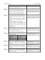
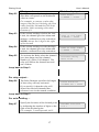
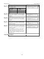
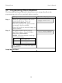
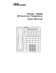
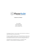
DiaLog Scout SPLC 12/24 Remote monitoring and alarm notification system User’s Manual Version 2.6 October 15, 2003 Antx, inc. P.O. Box 200816 Austin, TX 78720 877-686-2689 512-255-8306 (fax) www.antx.com 1 INTRODUCTION...................................................................................... 1 1.1 GENERAL OPERATION........................................................................... 1 1.1.1 Acknowledging Alarms ................................................................ 1 2 INSTALLATION....................................................................................... 2 2.1 ENABLING POWER ................................................................................. 3 2.2 CONNECTING THE SERIAL CABLE .......................................................... 4 2.3 CONFIGURING THE SERIAL PORT ........................................................... 4 2.4 ADJUSTING DISPLAY CONTRAST............................................................ 5 3 PROGRAMMING ..................................................................................... 6 3.1 HOW TO READ THE MENUS ................................................................... 6 3.2 PROGRAMMING SYSTEM SETTINGS ....................................................... 7 3.3 PROGRAMMING PHONE SETTINGS ....................................................... 10 3.4 PROGRAMMING CHANNEL SETTINGS .................................................. 12 3.5 PROGRAMMING PHONE NUMBERS ...................................................... 19 3.6 PROGRAMMING CHANNEL MODE ....................................................... 20 3.7 PROGRAMMING REMOTELY OVER A PHONE ......................................... 21 3.7.1 Phone numbers........................................................................... 21 3.7.2 Channel mode ............................................................................ 22 4 RUN MODE FUNCTIONS ..................................................................... 24 5 GETTING SYSTEM STATUS ............................................................... 24 5.1 FROM THE FRONT PANEL ..................................................................... 25 5.2 REMOTELY.......................................................................................... 26 6 VERIFYING COMMUNICATION ....................................................... 27 7 LISTENING IN FROM A REMOTE CALL ........................................ 28 8 ACKNOWLEDGING ALARMS............................................................ 28 8.1 ACKNOWLEDGE FROM THE KEYPAD .................................................... 29 8.2 ACKNOWLEDGE REMOTELY WHEN CALLED ........................................ 29 8.3 ACKNOWLEDGE WHEN YOU CALL IN ................................................... 30 9 ARMING AND DISARMING ................................................................ 31 9.1 FROM THE FRONT PANEL ..................................................................... 31 9.2 REMOTELY.......................................................................................... 31 10 WRITING COILS AND HOLDING REGISTERS .......................... 32 10.1 FROM THE FRONT PANEL ..................................................................... 32 10.2 REMOTELY.......................................................................................... 33 11 RETRIEVING THE EVENT LOG.................................................... 35 11.1 TO VIEW THE EVENT LOG LOCALLY.................................................... 35 11.2 TO RETRIEVE THE EVENT LOG REMOTELY .......................................... 36 12 REPLACING THE BACKUP BATTERY ........................................ 38 13 CUSTOMER SERVICE...................................................................... 39 14 FCC REGISTRATION ....................................................................... 39 DiaLog Scout User’s Manual 1 Introduction The DiaLog Scout SPLC6/10 is the most user-friendly and reliable remote monitoring and alarm notification system available. The Scout provides reading and writing of PLC/Modbus registers over a serial link using the Modbus RTU protocol. Mounted in an industrial aluminum enclosure, the Scout provides simple programming either locally through the integral keypad and display or remotely via a phone call. Installation is made easy, whether the Scout is installed in a panel or in a door. All wiring connections are made through quick disconnect type connectors, making it fast and simple. 1.1 General Operation The Scout SPLC reads inputs from a PLC or other Modbus device over a serial cable. Any input channel in the Scout can read/write the following registers from a PLC. Function Read coils Read digital status Read Holding Read Register Write Coil Write Holding Modbus Function Code 01 02 03 04 05 06 The Scout supports reading from multiple Modbus IDs, as each channel references a unique point specified by: Modbus slave ID Register type Register number The Scout has 2 modes of operation – PROGRAM and RUN. During PROGRAM mode you can change how the Scout operates. During RUN mode the Scout is monitoring and performing alarm notification. The Scout monitors up to 24 inputs continuously. When any one of the inputs changes from the normal condition to the alarm condition, the DiaLog Scout starts calling the first of up to 8 phone numbers to deliver the user recorded alarm message. 1.1.1 Acknowledging Alarms Alarms are acknowledged remotely by pressing the ‘9’ key on your phone keypad. The Scout tells you that the channel has been “acknowledged”. 1 DiaLog Scout User’s Manual 2 Installation You can mount the DiaLog Scout to a panel or it can be flush mounted to a door. The brackets on the either side of the Scout can be removed and turned around for panel mounting. Figure 1 Panel Mount mounting holes Figure 2 Flush Mount cut-out dimensions 2 DiaLog Scout User’s Manual The connectors for Primary Power and Phone use quick disconnect plugs. The diagram below shows the location of these connections. Figure 3 Field wiring diagram Connection point Function Phone Connect the included phone cord. Power Connect the included power connection from the wall-mount power supply to the Scout. Reset To supply power to the Scout, remove the plug. The Scout will power up and the display will read “DiaLog Scout”. To reset the power on the Scout, take a blade screwdriver and touch the 2 pins. 2.1 Enabling power The Scout is shipped electrically disabled. To enable the DiaLog Scout, remove the plastic jumper that is installed in the Reset location on the side of the Scout with the wiring connectors. NOTE: When the reset jumper is removed, the Scout will be running, there is no power on/off switch. To turn the Scout off, re-install the reset jumper. Remove reset jumper to enable power up of the Scout Save the jumper by installing it in the top pin only. 3 DiaLog Scout 2.2 User’s Manual Connecting the serial cable The Scout has a 9-pin connector located on the far right-hand side. The pin configuration is as follows: 1 2 3 CD RCV data XMT data 5 7 8 GND RTS CTS The cable between the Scout and the PLC/Modbus device will have to assure that the RCV on the Scout connects to the XMT on the PLC and visa versa. Serial Port 2.3 Configuring the serial port The serial port is configured for baud rate, message pacing and response time from the System Setup (3) function when in the Programming mode. Character Setup 8 bits, no parity, 1 stop bit (fixed) Baud Rate 0 – 2400 1 – 4800 2 - 9600 3 – 14400 4 – 19200 5 – 38400 6 – 57600 7 - 115200 Message Pacing 5 - 1000 Response Time 20-400 Maximum amount of time between each character of transmission from the PLC to the Scout msec Maximum amount of time the Scout will wait for a response from the PLC when a command has been issued msec 4 DiaLog Scout 2.4 User’s Manual Adjusting display contrast The contrast of the LCD display can be adjusted with a screwdriver by turning a potentiometer on the left-hand side of the board. The potentiometer is located as shown below. 5 DiaLog Scout User’s Manual 3 Programming The DiaLog Scout is programmed from the front panel by pressing the keypad to access the various portions of the system. For the most basic application, you can simply program some phone numbers and put the Scout into the RUN mode. In more complex applications, you can program individual messages for each channel being monitored, adjust the amount of time channels must be in the alarm condition before starting the callout sequence and enter phone and pager numbers for alarm notification. When programming, all prompts are displayed. You can enter a value or press the # key to keep the current value and move to the next option. To navigate the menu: Key Function # Accept the current entry *6 Go to the top of the Menu (HOME) *7 Reset the value back to the factory default NOTE: When you have finished programming, return the Scout to the RUN mode by pressing the 1 key. If the Scout is not in RUN mode, it will not perform any alarm call operations. If you forget to return the Scout to RUN mode, it will automatically return to RUN mode after 30 minutes. 3.1 How to Read the Menus Program Mode [0-9]= Mode or section of the system Available selections. In this case valid inputs are 0 through 9. Parameter to change or view Between Calls Delay 5-3600 secs = 30 Current value of the parameter. For example, Between Calls Delay is currently set to 30 seconds Valid range of values. Between 5 and 3600 seconds 6 DiaLog Scout 3.2 User’s Manual Programming System Settings System settings are generally programmed once during the initial setup of the Scout. Options in this section are: • • • • • • • Site Message Access Code Date and Time Country Code Numeric ID Rings to Answer Reset to System Defaults What you do: What the display shows: Step 1 Press the 1 key to enter PROGRAM mode. You can now enter options 0 – 9. Step 2 Press 3 Enter Access Code if requested. Step 3 The pre-recorded Site Message is spoken through the speaker. Press 0 to listen to the current message, 1 to record a new message, or # to move to the next step. If you press 1, this message is displayed. Program Mode [0-9]= NOTE: If an Access Code has been programmed, the Scout will show a screen to enter it. Site ID Msg 0-play 1-rec = Press # to record Speak you message into the microphone and press the # key when finished. NOTE: The speaker is intended only to confirm that you message was recorded as desired. The voice quality over the phone is excellent even though the voice quality over the speaker may be noisy. 7 Recording . . . Press # to stop DiaLog Scout Step 4 User’s Manual A 20 character name that is displayed on the screen. To enter the name, press the key that corresponds to the letter or number that you want. To move to the next character, wait 1 second between entries. Press # key when finished. For example, Character/# A B C 2 S System ID nnnnnnnnnnnnnnnnn How to enter 2 key – 1 time 2 key – 2 times 2 key – 3 times 2 key – 4 times 7 key – 3 times Step 4 The Numeric ID that will display on a pager is shown. Press # to keep the current value or enter a new value then press the # key. Step 5 The Access Code is displayed. Press # if OK or enter a new 4-digit Access Code. Step 6 The Audio Volume can be adjusted to be louder (up) or softer (down). Press # when you have the level you desire. NOTE: 7 is maximum volume level Audio Volume 0-dwn 1-up = 7 Step 7 Local Speaker specifies whether the speaker is on or off during alarm calls. If off, then the alarm call is not spoken over the local speaker. Local Speaker 0-off 1-on = off Step 8 Rings to Answer is the number of rings before the Scout answers. Press # if OK or enter a new value as nn (e.g. 03 for 3) Rings to Answer 1-20 = nn Step 9 If enabled, set the country code for the country where the Scout is located. 8 Numeric ID nnnnnnnnnnnnnnnnnn Access Code nnnn Country Code 0-nn = 0 US DiaLog Scout User’s Manual Step 10 Set the baud rate for the serial port. 0 – 2400 to 7 = 115200. Baud Rate 0-7 = 5 (38400) Step 11 Message pacing is the number of idle characters before the received message is accepted by the system. Msg Pacing 5-1000 = 10 Step 12 Response Timeout is the maximum amount of time the Scout waits for a response from the PLC. Resp Timeout(msec) 20-400 = 200 Step 13 Set the time and date as needed. Press the # key if the value is correct already. NOTE: The Scout uses a 24-hour clock. Set Hour 00-23 = nn Set Minute 00-59 = nn Set Month 01-12 = nn Set Day 01-31 = nn Set Year 02-99 = nn Step 14 Reset to Defaults sets the unit back to the factory default values. Press 0 or # to keep your programming or 1 to reset back to the factory defaults. 9 Reset to Defaults 1-rst = DiaLog Scout 3.3 User’s Manual Programming Phone Settings Phone settings consist of options to set for all calls in or out of the Scout. They are generally setup once during initial installation. Phone Settings include: • • • Message repeat Acknowledge redial delay Phone numbers Between call delay Call Progress delay What you do: What the display shows: Step 1 Press the 1 key for PROGRAM mode. You can now enter options 0 – 9. Step 2 Press 4 Enter Access Code if requested. Step 3 Msg Repeat is the number of times the alarm message will be repeated when an alarm call is made. Press # to keep the current value or enter a new value using 2 digits. (e.g. 03 for 3). Step 4 The Ack Redial Delay specifies the number of minutes to wait after an alarm has been acknowledged before calling again. NOTE: If the channel has returned to the normal condition, the Scout will not call. Press # to keep the current value or enter a new value using 4 digits. (e.g. 0060 for 60 minutes) Step 5 The Teach Mode allows the Scout to learn the ring pattern of the phone system that the Scout is connected to. Typical US systems have a 4-second pause and a 2-second ring pattern. 10 Program Mode 0-9 = NOTE: If the Scout is in RUN mode and an Access Code has been programmed, the Scout will show a screen to enter it. Msg Repeat 0-20 = nn Ack Redial Delay 1-1440 min = nnnn Teach Mode 1-teach = Teach Mode Press # to start… DiaLog Scout User’s Manual However, a number of PBX, digital systems and some private phone companies use other patterns. To have the Scout learn how your phone system work – press the 1 key – dial into the Scout and let it ring until it moves to the next screen Step 6 There are 8 phone numbers that can be entered in the Scout. These are processed in order from 1 to 8. Enter the position of the phone number you want to check or modify. Press # if you do not want to change any phone numbers. Step 6 The phone number in the position specified is shown. Press # if OK or enter a new phone number. NOTE: The phone number can be up to 25 numbers long. *2 *7 *8 *9 Teach Mode …waiting… Enter Phone Pos 1-8 = Pos 1 Phone Number nnnnnnnnnnnnnnnnn For a pager call Deletes phone number Detects a dialtone 2-second delay (e.g. 5124442233P would call a pager at 5124442233) Step 7 Specifies the amount of time to wait before calling the next number in the list. Step 8 This is the amount of time the Scout waits after issuing the last digit in the phone number before issuing the alarm or numeric pager message. NOTE: 0 means Call Progress is enabled. The Scout will call and wait until the phone has been answered before the alarm message is delivered. If the Scout calls and never delivers the message, then the Scout is not able to determine that the phone has been answered, probably because the voice answering the phone is not loud enough. 11 Pos 1 Next Call Dly 5-3600 secs = nnnn Pos 1 Call Prog Dly 0-60 secs = nn DiaLog Scout User’s Manual Loop back to Step 5 3.4 Programming Channel Settings This section allows you to configure the information specific to each channel or condition being monitored. For each channel the following options can be programmed. Types of Channels System (01) - Power Fail (02) - Low Battery (05) – Communications channel name channel message channel mode (alarm or status) alarm delay alarm type (normal or latched) PLC/Modbus channels (11-22) or (11-34) slave address register type register number channel message alpha ID Register type = read coil or read status channel mode channel state (Normally Open/Normally Closed) alarm delay alarm type (normal or latched) activate relay on alarm Register type = write coil pulse duration 12 DiaLog Scout User’s Manual Types of Channels PLC/Modbus channels Register type = read holding or read register channel mode alarm delay alarm type (normal or latched) decimal position engineering units min counts max counts zero in engineering units full scale in engineering units low limit high limit activate relay on alarm Register type = write holding decimal position min counts max counts zero in engineering units full scale in engineering units What you do: What the display shows: Step 1 Press the 1 key to enter PROGRAM mode. You can now enter options 0 – 9. Step 2 Press 9 Step 3 Enter the Channel Number that you wish to examine or program. NOTE: Press # to back-up the menu. Step 4 Enter the Modbus Slave ID of the remote PLC or device that this channel will be read from. 0 = disabled Enter the type of Modbus register that this channel will read or write. 1 – Read Coil (digital in) 2 – Read Status (digital in) 3 – Read Holding Register (analog in) Step 5 13 Program Mode 0-9 = Enter Chan Number 0x,11-34 = Slave Address 0-247 = Register Type 1-6 = DiaLog Scout User’s Manual What you do: 4 – Read Register (analog in) 5 – Write Coil (relay out) 6 – Write Holding Register (analog out) Step 6 Enter the register number to read/write in the PLC or Modbus device. Step 7 The Scout will repeat the current channel message. If the message is OK, press #. To record a new message, press 1 and speak your new 6-second message into the microphone followed by the # key. To listen to the current message again, press 0. Step 8 Each channel can have a 20 character name that will be displayed whenever the Status is shown or a channel is in alarm. To enter the name, press the key that corresponds to the letter or number that you want. To move to the next character, wait 1 second between entries. Press # key when finished. For example, Character/# How to enter A 2 key – 1 time B 2 key – 2 times C 2 key – 3 times 2 2 key – 4 times S 7 key – 3 times What the display shows: Register Number 1-9999 = Chan 11 Alarm Msg 0-play 1-rec = Chan 11 Alpha ID nnnnnnnnnnnnnnnnn For Register Type = Read Coil or Read Status jump to Step 9. For Register Type = Read Holding or Read Register jump to Step 14. For Register Type = Write Coil jump to Step 26. For Register Type = Write Holding jump to Step 27. For Read Coil… Step 9 The Channel Mode should be set to 1 for Call on Alarm conditions or 0 for 14 Chan 11 Mode 0-stat 1-alm = 1 DiaLog Scout User’s Manual What you do: Status Only. Press # if the value is OK. What the display shows: Step 10 The Alarm State is 0 for normally open and 1 for normally closed. NOTE: An alarm occurs when the Scout transitions out of these ‘normal’ conditions. Step 11 The Alarm Delay specifies the amount of time the input must be in the alarm condition before a call-out begins. Press # if OK or enter a new 5-digit value as nnnnn (e.g. 00300 for 300) Step 12 The Alarm Type specifies whether the alarm tracks the input signal condition or not. 0 (normal) indicates the alarm condition follows the input signal in and out of alarm. 1 (latch) indicates once an alarm condition occurs it will continue to call until the channel is acknowledged AND the input signal goes back to the normal condition. Press # if OK. Step 13 To Activate the Relay when the channel goes into alarm enter the channel number of a Write Coil channel. NOTE: The relay will follow the channel into and out of alarm. Chan 11 Normal State 0-n/o 1-n/c = 0 Chan 11 Alarm Delay 0-65535 sec = nnnnn Chan 11 Alarm Type 0-norm 1-latch = 0 Activate Relay Chan 11-34 Loop back to Step 3 For read holding and read register … Step 14 The Channel Mode should be set to 1 for Call on Alarm conditions or 0 for 15 Chan 11 Mode 0-stat 1-alm = 1 DiaLog Scout User’s Manual What you do: Status Only. Press # if the value is OK. What the display shows: Step 15 The Alarm Delay specifies the amount of time the input must be in the alarm condition before a call-out begins. Press # if OK or enter a new 5-digit value as nnnnn (e.g. 00300 for 300) Step 16 The Alarm Type specifies whether the alarm tracks the input signal condition or not. 0 (normal) indicates the alarm condition follows the input signal in and out of alarm. 1 (latch) indicates once an alarm condition occurs it will continue to call until the channel is acknowledged AND the input signal goes back to the normal condition. Press # if OK. Step 17 Specify the location of the decimal point by indicating the number of digits to the right of the decimal point. For example, 2 would provide 44.33 Step 18 Specify the engineering units to use for this analog value. 0 – none 1 – deg 2 – gals 3 – gpm 4 – gph 5 – ppm 6 – psi 7 – pct 8 - ft Step 19 Specify the minimum value in counts that will be read from the PLC/Modbus register. Min Counts 0-65535 = 0 Step 20 Specify the maximum value in counts that will be read from the PLC/Modbus register. Max Counts 0-65535 = 32767 Step 21 Specify the zero value in engineering units that corresponds to the minimum value in counts. Zero 0-99999 = 0 16 Chan 11 Alarm Delay 0-65535 sec = nnnnn Chan 11 Alarm Type 0-norm 1-latch = 0 Decimal Position 0-5 = Engineering Units 0-8 = 1 (deg) DiaLog Scout Step 22 User’s Manual What you do: Specify the span value in engineering units that corresponds to the minimum value in counts. For example, to convert a value that ranges from 20.0 to 100.0 deg, the Zero value would be 200 and the Full Scale would be 1000, assuming a Decimal Position of 1. Step 23 If the current reading is below the Low Limit, the channel goes into alarm and initiates a call and/or a relay activation. NOTE: always has 1 digit to the right of the decimal Step 24 If the current reading exceeds the High Limit, the channel goes into alarm and initiates a call and/or a relay activation. Step 25 To Activate the Relay when the channel goes into alarm enter the channel number of a Write Coil channel. The relay will follow the channel into and out of alarm. What the display shows: Full Scale 0-99999 = 10000 Chan 31 Low Limit 0-99999 = xxxxx Chan 31 High Limit 0-99999 = xxxxx Activate Relay Chan 11-34 Loop back to Step 3 For relay output… Step 26 The Pulse Duration specifies the length of time relay will stay activated. If you specify 0, then the relay will deactivate when all channels that reference it are in the normal condition. Pulse Duration 0-86400 sec = nnnnn Loop back to Step 3 For write holding … Step 27 Specify the location of the decimal point by indicating the number of digits to the right of the decimal point. For example, 2 would provide 44.33 17 Decimal Position 0-5 = DiaLog Scout Step 18 User’s Manual What you do: Specify the engineering units to use for this analog value. 0 – none 1 – deg 2 – gals 3 – gpm 4 – gph 5 – ppm 6 – psi 7 – pct 8 - ft What the display shows: Engineering Units 0-8 = 1 (deg) Step 28 Specify the minimum value in counts that will be written to the PLC/Modbus register. Min Counts 0-65535 = 0 Step 29 Specify the maximum value in counts that will be written to the PLC/Modbus register. Max Counts 0-65535 = 32767 Step 30 Specify the zero value in engineering units that corresponds to the minimum value in counts. Zero 0-99999 = 0 Step 31 Specify the span value in engineering units that corresponds to the minimum value in counts. For example, to convert a value that ranges from 20.0 to 100.0, the Zero value would be 200 and the Full Scale would be 1000, assuming a Decimal Position of 1. Loop back to Step 3 18 Full Scale 0-99999 = 10000 DiaLog Scout 3.5 User’s Manual Programming Phone Numbers The Scout has an Express Key (6), that allows you to jump directly to the programming section for a particular phone number. What you do: What the display shows: Step 1 There are 8 phone numbers that can be entered in the Scout. These are processed in order from 1 to 8. Enter the position of the phone number you want to check or modify. Press # if you do not want to change any phone numbers. Step 2 The phone number in the position specified is shown. Press # if OK or enter a new phone number. NOTE: The phone number can be up to 25 numbers long. *2 *7 *8 *9 For a pager call Deletes phone number Detects a dialtone 2-second delay (e.g. 5124442233P would call a pager at 5124442233) Loop back to Step 1 19 Enter Phone Pos 1-8 = Pos 1 Phone Number nnnnnnnnnnnnnnnnn DiaLog Scout 3.6 User’s Manual Programming Channel Mode The Scout has an Express Key (8), that allows you to jump directly to the programming section for a particular channel number. What you do: What the display shows: Step 1 Enter the Channel Number that you wish to examine or program. Press # to back-up the menu. Step 2 The Channel Mode should be set to 1 for Call on Alarm conditions or 0 for Status Only. Press # if the value is OK. Enter Chan Number 0x,1x,21,3x= Chan 31 Mode 0-status 1-alm = 1 For read coil and status inputs… Step 3 The Alarm State is 0 for normally open and 1 for normally closed. NOTE: An alarm occurs when the Scout transitions out of these ‘normal’ conditions. Chan 31 Normal State 0-n/o 1-n/c = 0 Loop back to Step 1 For holding and register inputs… Step 4 If the current reading is below the Low Limit, the channel goes into alarm and initiates a call and/or a relay activation. Chan 31 Low Limit 0-99999 = xxxxxx Step 5 If the current reading exceeds the High Limit, the channel goes into alarm and initiates a call and/or a relay activation. Chan 31 High Limit 0-99999 = xxxxx Loop back to Step 1 20 DiaLog Scout 3.7 User’s Manual Programming remotely over a phone There are 2 functions that can be programmed from a remote call-in – Phone Numbers and Channel Mode. When you call-in, the Scout will: • Answer the phone • Repeat the current status • 3 “beeps” You have 5 seconds after the 3 ‘beeps’ to press the # key on your phone to inform the Scout that you want to perform remote programming. After pressing the # key, the Scout will say “System ready, enter selection.” 3.7.1 Phone numbers What you do: What the Scout says: Press # within 5 seconds of hearing the 3 “beeps” “System ready. Enter selection.” Press 6 or press # if finished. NOTE: If an Access Code is programmed, the Scout says“Enter Access Code” Enter Access Code if requested “Phone setup. Enter phone position. Or press # to exit” Step 2 Enter position number 1-8. Press # when finished. “Position” nn “Phone number is” nnnnnnnnnnnn Step 3 Press # if the number is OK or enter a new number followed by the # key. NOTE: The phone number can be up to 25 numbers long. “Position” nn “Phone number is” nnnnnnnnnnnn “Enter new number or press # to exit” Step 1 *2 *7 *8 *9 For a pager call Deletes phone number Detects a dialtone 2-second delay (e.g. 5124442233P would call a pager at 5124442233) Loop back to Step 2 21 DiaLog Scout 3.7.2 User’s Manual Channel mode What you do: What the Scout says: “System ready. Enter selection.” Step 1 Step 2 Press 8 or press # if finished. NOTE: If an Access Code is been programmed, the Scout says “Enter Access Code” Enter Access Code if requested. “Channel setup.” Enter a channel number “Enter channel number or press # to exit” For Digital Inputs… Step 3 Enter channel number 1x Press # when finished. “Digital input channel nn” “The mode is” “status only” or “call on alarm” “Enter new selection or press # to exit” Step 4 Press 0 for status only. (no alarm calls) Press 1 for call on alarm. “Digital input channel nn” “The mode is” “status only” or “call on alarm” NOTE: Your entry is repeated back to you. “Digital input channel nn” “Alarm state is normally” “open” or “closed”. Press 0 for normally open or 1 for normally closed. “Digital input channel nn” “Alarm state is normally” “open” or “closed”. “Enter new selection or press # to exit” Step 5 Loop back to Step 2 For analog inputs… Step 6 Enter channel number 3x Press # when finished. “Analog input channel nn” “The mode is” “status only” or “call on alarm” “Enter new selection or press # to exit” 22 DiaLog Scout User’s Manual Step 7 Press 0 for status only. (no alarm calls) Press 1 for call on alarm. “Analog input channel nn” “The mode is” “status only” or “call on alarm” Step 8 Enter a new low limit with 1 assumed digit to the right of the decimal, or # if the current value is OK. Enter *7 to disable the low limit. e.g. 252 would be 25.2 % “Analog input channel nn” “low limit is nn.n %” “Enter new selection or press # to exit” NOTE: Your entry is repeated back to you. “Analog input channel nn” “low limit is nn.n %” Enter a new high limit with 1 assumed digit to the right of the decimal. Enter *7 to disable the high limit. e.g. 850 would be 85.0 % “Analog input channel nn” “high limit is nn.n %” “Enter new selection or press # to exit” NOTE: Your entry is repeated back to you. “Analog input channel nn” “high limit is nn.n %” Step 9 Loop back to Step 2 23 DiaLog Scout User’s Manual 4 RUN Mode functions While the Scout is in RUN mode it is scanning all inputs, evaluating them for transitions into and out of alarm conditions, performing alarm calls and updating the display. The default RUN mode display looks like this: Run Mode 03:02:02 Alms or Acked Phone Status (offhk, ring, delay, pherr) Armed or Disarm There are 7 functions that can be performed while in RUN mode. Function Capability Keypad 0 Keypad 1 Keypad 2 Keypad 5 Keypad 7 Keypad 9 Keypad * # Get system status Enter Program mode Toggle Arm/Disarm View Event Log Activate Relay Acknowledge alarms Test phone line 5 Getting System Status System Status reports the current conditions of the DiaLog Scout. It will report any channels that are in alarm or acknowledged, including the primary power, battery and communications channels. 24 DiaLog Scout 5.1 User’s Manual From the front panel The Scout displays the first channel (Power). To view the other channels press the A key to move backward or the B key to move forward through all the channels. The channels are: Power, Low Battery, Low Low Battery, Phone line status, each input channel and then the version of the firmware in the Scout. What you do: What the display shows: Step 1 Press the 0 key. Step 2 Primary power is being supplied. Press the B key. Power normal Battery level is normal. Press the B key. Low Batt normal Battery level is normal. Press the B key. Low Low Batt normal Phone line is connected and has a dialtone. Press the B key. Serial communication channel is in alarm and cannot communicate with the device on Modbus ID 15. Press the B key. Phone normal Comm id: 15 in alm Channel 11 is in the normal condition and is open. Press the B key. Chan 11 in alm Press 0 again, to get information about the programming for that channel. e.g. ID 15, read holding, register 200. Chan 11 15 Rd Holding 200 23.4 ft Loop through remaining channels DiaLog Scout version Ver v1.x SPLCxx Loop back to Step 1 NOTE: Press any key on the keypad to stop the System Status display. 25 DiaLog Scout 5.2 User’s Manual Remotely The System Status can be retrieved remotely by calling into the Scout from a phone. The Scout will answer after the number of rings specified by Rings to Answer. Then the Scout will: What you do: What the Scout says: Step 1 Dial the DiaLog Scout phone number Site ID Message (followed by any channels in alarm) beep beep beep Step 2 Press the # key. (within 5 seconds) “System ready. Enter selection.” Step 3 Press 0 “System status.” The System Status report is spoken. “Enter channel number or press # to exit” Step 4 Enter a channel number Channel message “is normal/in alarm’ “The present value is open/closed” or “The present value is xx.x ” Loop back to Step 3 or enter # to exit 26 DiaLog Scout User’s Manual 6 Verifying Communication When a channel is configured to read from a PLC or Modbus device, the Scout reads all channels every ½ second. If the Scout is not able to communicate correctly, the state of the Communication channel (05) will show an alarm. NOTE: If communication with a Modbus device is lost, the Communication channel will not go into alarm until the Alarm Delay period, which is defaulted to 10 seconds. To verify that the Scout is reading values correctly, look at the Status (3) of the Communication channel (05). Serial communication channel indicates that all communications is operating properly. Serial communication channel indicates that the communications with Modbus Slave ID 122 is not working. Potential causes are: 1. 2. 3. 4. 5. 6. Comm norm Comm id: 122 in alm The serial cable is disconnected. The ID is not correct. The Baud Bate is not correct. The Register Type or Register Number are not correct. The Message Pacing needs to be increased. The Time to Respond needs to be increased. If some channels are being read and others are not, check the Status for each channel to determine which are having problems. Input channel indicates that the channel is in alarm and there is a loss of communication. Chan xx <status> The <status> field switches between the alarm condition and a communication failure. For example, In alm and Comm 27 0.00 ppm DiaLog Scout User’s Manual 7 Listening In from a remote call The DiaLog Scout allows you to call into it from a phone and Listen-In on the noise around the Scout. This is typically used to determine if motors, pumps, fans, etc. are running. What you do: What the Scout says: Step 1 Dial the DiaLog Scout phone number Site ID Message (followed by any channels in alarm) beep beep beep Step 2 Press the # key “System ready. Enter selection.” Step 3 Press the 5 key to enable Listen-In The Scout’s microphone is turned on for 40 seconds. Press the # key during the 40 seconds. Disables Listen-In “System ready. Enter selection.” 8 Acknowledging alarms A channel goes into alarm when it transitions out of the normal condition specified in the Alarm State. For example, if a channel has an Alarm State of Normally Open, then the channel goes into alarm when the input closes. The channel will stay in alarm as long as the input is closed. If the Alarm Type is set to Latching, then it will stay in alarm, even if the input goes back to open, until the channel is acknowledged. When any channel goes into alarm and the Channel Mode is set to Call on Alarm, the Scout will start calling the phone numbers in the Phone List. It will continue to call through the list of phone numbers until the channel goes out of alarm or until it is acknowledged. When acknowledged, the Scout will stop calling and wait the time specified by the Ack Redial Delay before starting to call again if the channel is still in the alarm condition. 28 DiaLog Scout 8.1 User’s Manual Acknowledge from the keypad While in RUN mode, press the 9 key. The Scout will change the display information for the channel(s) in alarm from Alarm to Acknowledged and stop calling. 8.2 Acknowledge remotely when called The Scout calls the phone numbers programmed into the Phone List beginning with the first position. If the call is busy, the Scout will go to the next number. What you do: What the Scout does: Step 1 Calls next phone number. Step 2 Waits time specified by the Call Progress Delay for that phone number. Step 3 Says: Site Message ID Channel Message ID “is in alarm” “please acknowledge” You have 5 seconds to press the 9 key to acknowledge the alarm. If you do not acknowledge, loop back to Step 3 the number of times specified by Msg Repeat If you do acknowledge “Channel acknowledged.” beep beep beep NOTE: After all the channels have been spoken, the Scout will give you three (3) beeps. You have 5 seconds to press the # key if you wish to continue. If you do not press the # key. “Good-bye” 29 DiaLog Scout 8.3 User’s Manual Acknowledge when you call in If you receive a pager notification that a channel is in alarm and you call into the Scout, the Scout asks you to acknowledge any alarms. Step 1 What you do: What the Scout does: Call into the Scout Says: Site Message ID Channel Message ID “is in alarm” “Please acknowledge” You have 5 seconds to press the 9 key to acknowledge the alarm. If you do acknowledge “Channel acknowledged.” beep beep beep NOTE: After all the channels have been spoken, the Scout will give you three (3) beeps. You have 5 seconds to press the # key if you wish to continue. If you do not press the # key. “Good-bye” 30 DiaLog Scout User’s Manual 9 Arming and Disarming At times it may be beneficial to Disarm the Scout to prevent it from calling out. This is generally done when you are performing maintenance on equipment being monitored and do not want unnecessary alarms generated. NOTE: When the Scout is disarmed, all scanning of I/O stops. You can manually write to coils and holding registers either locally or remotely. 9.1 From the front panel NOTE: The Scout must be in the RUN mode What you do: Step 1 What the display shows: Press the 2 key to toggle between Armed and Disarmed. Run Mode armed 03:04:07 NOTE: If the Scout is Disarmed, it will automatically become Armed after 30 minutes. 9.2 Remotely You can Arm or Disarm the Scout when you call into it. What you do: What the Scout says: Step 1 Dial the DiaLog Scout phone number Site ID Message (followed by any channels in alarm) beep beep beep Step 2 Press the # key within 5 seconds “System ready. Enter selection.” If an Access Code has been activated, you will be requested to enter it. Step 3 Press 2 to toggle between arm/disarm. “System is armed/disarmed” “Return to arm in 30 minutes” “System ready. Enter selection.” Loop back to Step 2 31 DiaLog Scout User’s Manual 10 Writing Coils and Holding Registers Coils and Holding Registers can be written to manually either locally from the keypad or remotely over a phone. Both of these functions are activated by pressing the 7 key. If the coil is also controlled via a digital or analog channel going into alarm, the coil will perform the programmed function in addition to any manual operations. 10.1 From the front panel NOTE: The Scout must be in the RUN mode What you do: Step 1 What the display shows: Press the 7 key to see the Output Channels selection screen. Enter the channel number for the Write Coil or Write Holding Register. Output Channels Chan 11-20 = xx If the Channel number is a Holding Register, go to Step 3. Step 2 The channel is a Write Coil. Enter 0 to deactivate the coil (relay) or 1 to activate. NOTE: Once the command has been accepted, the value to the right of the ‘=’ will be the actual read back value of the coil. Therefore, if the command entered was a ‘1’ to activate and the display shows ‘ = 0’, the coil was not set and there may be a communication problem. Relay Output xx 0-deact 1-act = Loop back to Step 1 Step 3 The channel is a Write Holding. The value xx.xx represents the last value read back from this holding register. For example (assume 2 decimal places): You enter: Set = 5629# If the write was successful, 56.29 will be displayed as the value read back from this holding register. 32 Analog Output xx xx.xx Set = DiaLog Scout User’s Manual You may now enter a new value for this holding register. The value is entered as 1 to 5 consecutive numbers. If the pound key is pressed and no numbers have been entered, the system returns to prompt for an output channel number. When the # key is pressed, the number is rewritten showing the decimal point location. If this value is correct, press the pound key to write the new value to the holding register. If the value is not correct, hit any key except the pound key to abort this entry and reenter a new value. Loop back to Step 1 10.2 Remotely You can activate or deactivate the relay when you call into the Scout or when the Scout has called you during an alarm notification. What you do: What the Scout says: Step 1 Dial the DiaLog Scout phone number Site ID Message (followed by any channels in alarm) beep beep beep Step 2 Press the # key within 5 seconds “System ready. Enter selection.” If an Access Code has been activated, you will be requested to enter it. Step 3 Press 7 to listen to the Output Channels prompt. “Output Channels. ” “Enter channel number or press # to exit.” If the Channel number is a Holding Register, go to Step 6. Step 4 Recorded channel message or “Relay output channel nn” “Relay is energized/deenergized” “Enter new selection” Enter channel number. For a write coil channel 33 DiaLog Scout Step 5 User’s Manual Press 1 to activate the relay or 0 to deactivate the relay. The new state of the coil is the read back to you. Press the pound key to return to the channel prompt. “Relay is energized (or deenergized)” “Enter new selection or press # to exit.” Loop back to Step 1 Step 6 Enter channel number. For a write holding channel “Analog output channel nn” “The present value is xx.xx” “Enter new value or press # to exit” Step 7 Enter a new value. For example, 5678# “The new value is 56.78” “Press # to enter “Enter new value or press # to exit.” Step 8 If this value is correct, press the pound key to write the value to the holding register. NOTE: If the value is not correct, hit any other key to abort this entry and reenter a new value. If the entry is aborted the system says “No Entry”. “The present value is 56.78” “Press # to enter “Enter new value or press # to exit.” Loop back to Step 1 34 DiaLog Scout User’s Manual 11 Retrieving the Event Log The DiaLog Scout keeps the last 100 events that occurred in a local non-volatile log. The Event Log can be viewed locally on the display or retrieved remotely over the phone. 11.1 To view the Event Log locally What you do: What the display shows: Step 1 Press the 5 key Step 2 Press the B key to advance forward through the Event Log or the A key to move backward. 1) PROG Mode date time Press the # key when you are finished. Press # when finished 35 2) DIN3 Cl Alm date time DiaLog Scout User’s Manual 11.2 To retrieve the Event Log remotely The Event Log can be retrieved remotely via a phone call in to the DiaLog Scout. What you do: What the Scout says: Step 1 Dial the DiaLog Scout phone number Site ID Message (followed by any channels in alarm) beep beep beep Step 2 Press the # key (within 5 seconds) “Enter selection.” Step 3 Press the 3 key. “Event log start” “Type is # <optional value>’ “Date is xx xx” “Time is xx xx xx” Step 4 Press the 1 key to move to the next event, press the 0 key to move to the previous event. “Type is # <optional value>’ “Date is xx xx” “Time is xx xx xx” NOTE: if the Date is the same as the previous event, then the date will not be repeated. If the time is the same as the previous event, then the time will not be repeated. NOTE: the Scout will say “Event log end” prior to the type of the last entry in the event log. Loop back to Step 4 or press # to exit. 36 DiaLog Scout Type # User’s Manual Event Description Optional value 0 NULL Event 1 2 3 4 5 6 7 8 Power On Dead Task Armed Disarmed RUN Mode PROGram Mode Configuration Change Set Defaults 9 10 11 12 13 14 15 16 17 Call Answered No Dial Tone Phone Busy Call Error Call Aborted Call Timeout Call No Answer Call Incoming Call Complete 18 19 Local Ack Remote Ack 20 21 22 23 24 Alarm Call Open Alarm Closed Alarm Low Alarm High Alarm Channel number Channel number Channel number Channel number 25 26 27 28 29 Channel Normal Channel Acked Relay On Relay Off Preset Holding Register Channel number Channel number Channel number Channel number Channel number 30 Unknown Task Number 37 DiaLog Scout User’s Manual 12 Replacing the Backup Battery The Backup Battery is continually monitored by the Scout to confirm that it is supplying enough power to run the Scout. If it is not, then the Low Battery (02) alarm will be activated. This alarm is caused by: 1. the Scout has lost Primary Power, is running on the battery and is low on power, or 2. the battery cannot be recharged, which should take 6-12 hours. The Backup Battery is located inside the enclosure. You will have to remove the front panel from the enclosure to expose the battery. Step 1 Battery replacement procedure If panel mounted, dismount the enclosure by loosening the screws holding the enclosure to the panel. Step 2 Remove the four (4) nuts that hold the front cover to the enclosure. Step 3 Slowly tilt the top edge of the front cover away from the enclosure to expose the cable connecting the electronics to the battery. Step 4 Put the front cover in a safe place and remove the battery bracket and battery. Step 5 Put the new battery in the bracket with the leads facing the left-hand side of the enclosure. Step 6 Reattach the battery cable and front cover. Step 7 Mount the enclosure back in place. NOTE: be careful when removing the front panel as it holds the electronics and there is a cable between the electronics and the battery. 38 DiaLog Scout User’s Manual 13 Customer Service Antx customer service can be reached toll-free at 877-686-2689. Antx, inc. P.O. Box 200816 Austin, TX 78720 www.antx.com [email protected] 14 FCC Registration The Federal Communications Commission (FCC) has established rules that permit this device to be directly connected to the telephone network. Standardized jacks are used for these connections. This equipment should not be used on party lines or coin lines. If this device is malfunctioning, it may also be causing harm to the telephone network. This device should be disconnected until the source of the problem can be determined and until repair has been made. If this is not done, the telephone company may temporarily disconnect service. The telephone company may make changes in its technical operations and procedures. If such changes affect the compatibility or use of this device, the telephone company is required to give adequate notice of the changes. You will be advised of your right to file a complaint with the FCC. If the telephone company requests information on what equipment is connected to their lines, inform them of: a. The telephone number this unit is connected to b. The ringer equivalence number: 0.2B c. The USOC jack required d. The FCC registration number: 60DAL02BSCOUT Items b and d are indicated on the label. The ringer equivalence (REN) is used to determine how many devices can be connected to your telephone line. In most areas, the sum of the REN's of all devices on any one line should not exceed five. If too many devices are attached, they may not ring properly. 39 DiaLog Scout User’s Manual 40 Antx, inc. P.O. Box 200816 Austin, TX 78720 512/255-2800 512/255-8306 (fax) www.antx.com