1
X9 SMM IPMI
User's Guide
Revision 1.0
The information in this User’s Manual has been carefully reviewed and is believed to be accurate.
The vendor assumes no responsibility for any inaccuracies that may be contained in this document,
makes no commitment to update or to keep current the information in this manual, or to notify any
person or organization of the updates. Please Note: For the most up-to-date version of this
manual, please see our web site at www.supermicro.com.
Super Micro Computer, Inc. ("Supermicro") reserves the right to make changes to the product
described in this manual at any time and without notice. This product, including software and documentation, is the property of Supermicro and/or its licensors, and is supplied only under a license.
Any use or reproduction of this product is not allowed, except as expressly permitted by the terms
of said license.
IN NO EVENT WILL SUPER MICRO COMPUTER, INC. BE LIABLE FOR DIRECT, INDIRECT,
SPECIAL, INCIDENTAL, SPECULATIVE OR CONSEQUENTIAL DAMAGES ARISING FROM THE
USE OR INABILITY TO USE THIS PRODUCT OR DOCUMENTATION, EVEN IF ADVISED OF
THE POSSIBILITY OF SUCH DAMAGES. IN PARTICULAR, SUPER MICRO COMPUTER, INC.
SHALL NOT HAVE LIABILITY FOR ANY HARDWARE, SOFTWARE, OR DATA STORED OR USED
WITH THE PRODUCT, INCLUDING THE COSTS OF REPAIRING, REPLACING, INTEGRATING,
INSTALLING OR RECOVERING SUCH HARDWARE, SOFTWARE, OR DATA.
Any disputes arising between manufacturer and customer shall be governed by the laws of Santa
Clara County in the State of California, USA. The State of California, County of Santa Clara shall be
the exclusive venue for the resolution of any such disputes. Supermicro's total liability for all claims
will not exceed the price paid for the hardware product.
FCC Statement: Refer to Supermicro's web site for FCC Compliance Information.
California Best Management Practices Regulations for Perchlorate Materials: This Perchlorate
warning applies only to products containing CR (Manganese Dioxide) Lithium coin cells. “Perchlorate
Material-special handling may apply. See www.dtsc.ca.gov/hazardouswaste/perchlorate”.
WARNING: Handling of lead solder materials used in this
product may expose you to lead, a chemical known to
the State of California to cause birth defects and other
reproductive harm.
Manual Revision 1.0
Release Date: January 16, 2013
Unless you request and receive written permission from Super Micro Computer, Inc., you may not
copy any part of this document.
Information in this document is subject to change without notice. Other products and companies
referred to herein are trademarks or registered trademarks of their respective companies or mark
holders.
Copyright © 2013 by Super Micro Computer, Inc.
All rights reserved.
Printed in the United States of America
Preface
Preface
About this User's Guide
This user guide is written for system integrators, PC technicians and
knowledgeable PC users who intend to configure the IPMI settings supported by
the Renesas SH7757 Baseboad Management Controller (BMC) embedded in Supermicro's motherboards. It provides detailed information on how to configure the
IPMI settings supported by the Renesas SH7757 BMC chip.
User's Guide Organization
Chapter 1 provides an overview to the IPMI Controller. It also introduces the features and the functionality of IPMI.
Chapter 2 provides detailed instructions on how to configure the IPMI settings
supported by the Renesas SH7757 Controller.
Appendix A provides detailed information on Flash Tools.
Conventions Used in the User's Guide
Special attention should be given to the following symbols for proper IPMI configuration.
Warning: Important information given to avoid IPMI configuration errors.
Note: Additional information given to ensure correct IPMI configuration
and proper system setup.
iii
X9 SMM IPMI User's Guide
Contacting Supermicro
Headquarters
Address:
Tel:
Fax:
Email:
Web Site:
Europe
Address:
Tel:
Fax:
Email:
Asia-Pacific
Address:
Tel:
Fax:
Web Site:
Email:
Tel: Super Micro Computer, Inc.
980 Rock Ave.
San Jose, CA 95131 U.S.A.
+1 (408) 503-8000
+1 (408) 503-8008
[email protected] (General Information)
[email protected] (Technical Support)
www.supermicro.com
Super Micro Computer B.V.
Het Sterrenbeeld 28, 5215 ML
's-Hertogenbosch, The Netherlands
+31 (0) 73-6400390
+31 (0) 73-6416525
[email protected] (General Information)
[email protected] (Technical Support)
[email protected] (Customer Support)
Super Micro Computer, Inc.
4F, No. 232-1, Liancheng Rd.
Chung-Ho Dist., New Taipei City 235
Taiwan, R.O.C.
+886-(2) 8226-3990
+886-(2) 8226-3991
www.supermicro.com.tw
[email protected] (Technical Support)
+886-(2) 8226-3990 (Technical Support)
iv
Preface
Notes
v
X9 SMM IPMI User's Guide
Table of Contents
Preface
Chapter 1 Introduction...............................................................................1-1
1-1
An Overview of the Renesas SH7757 BMC Controller................................... 1-1
1-2
SH7757 Block Diagram.................................................................................... 1-2
1-3
A Brief Introduction to the IPMI........................................................................ 1-2
1-4 Supported Motherboards and Blades.............................................................. 1-3
1-5 An Important Note to the User......................................................................... 1-3
Chapter 2 Configuring the IPMI Settings................................................. 2-1
2-1
Configuring BIOS IPMI Settings...................................................................... 2-1
Enabling COM Port for SOL (IPMI)................................................................. 2-1
Enabling All Onboard USB ports..................................................................... 2-2
Configuring the IP Address Using the BIOS.................................................... 2-2
Configuring IP Addresses Using the IPMICFG Utility...................................... 2-4
2-2
Accessing the Remote Server from a Browser on Your Computer................. 2-6
2.2.1 To Log In................................................................................................. 2-7
2.2.2 IPMI Main Page...................................................................................... 2-8
2.3 Summary.................................................................................................... 2-9
2.4 FRU Information........................................................................................2-11
2.5 System Information.................................................................................. 2-13
2.6 Configuration............................................................................................ 2-19
2.7 Remote Control........................................................................................ 2-57
2.8 Auto Video Recording.............................................................................. 2-74
2.9 Maintenance............................................................................................. 2-77
2.10 Miscellaneous........................................................................................ 2-82
Appendix A Flash Tools ......................................................................... A-1
A-1 Overview..........................................................................................................A-1
A-2 Flashing the BMC Firmware in the DOS Environment....................................A-1
Examples..........................................................................................................A-2
A-3 Flashing the BMC Firmware in the Windows Environment.............................A-3
Examples..........................................................................................................A-4
A-4 Flashing the BMC Firmware in the Linux Environment...................................A-6
Examples..........................................................................................................A-7
vi
Chapter 1: Introduction
Chapter 1
Introduction
1-1 An Overview of the Renesas SH7757 BMC Controller
The Renesas SH7757 controller is integrated with a robust set of peripheral functions that are necssary for a Baseboard Management Controller (BMC). The RISC
(Reduced Instruction Set Computing) CPU core built into the Reneasas SH7757
controller offers the user a superb solution to manage PCserver systems with great
efficiency.
The Renesas SH7757 BMC supports 256 GB of memory and a speed of up to 576
MHz. The motherboard also supports an additional 32 MB of Flash memory to store
the firmware. The controller provides on-chip Memory Management Unit (MMU),
which yeilds up to 4 GB of virtual address space.
Renesas SH7757 Peripheral Functions
The Renesas SH7757 supports a variety of functions to manage a system. To enable display redirection and recreation for remote system management, the Renesas
SH7757 graphics controller integrates a PCI 3.0 Matrox G200 interface with a video
data compressor to support Keyboard/Video/Mouse (KVM). The Renesas SH7757
also supports an I2C bus interface, and LPC bus interface, two ethernet controllers,
serial communication interfaces, and USB media hosting.
Other Renesas SH7757 Subsystem Features Supported
•Network Connections: Two Gigabit connections (one dedicated LAN connection
and one shared LAN with an onboard LAN controller)
•1600 x 1200 resolution at 32 bpp (bits per pixel) and 75 Hz
•1680 x 1050 widescreen resolution at 32bpp and 60 Hz
•Hardware video compression with maximum resolution of 1600 x 1200 with
16-bit color (for KVM)
•Shared-memory type 16 MB frame buffer controller
1-1
X9 SMM IPMI User's Guide
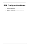
1-2 SH7757 Block Diagram
The following diagram represents a typical system setup for the Renesas SH7757
Controller.
PROCESSOR
PECI
USB 2.0
USB 2.0
PCIEx1
LPC
Wake-up & CTRL
PCH
RMII
Serial Port
SH7757
RMII
VGA
Sensors
SPI
PHY
RJ45 LAN
for CMM1
RS232
Serial Port
PHY
RJ45 LAN
for CMM2
NOR Flash
DDR3
1-3 A Brief Introduction to the IPMI
The basic function of the Intelligent Platform Management Interface (IPMI) is
to provide remote access to multiple users from different locations. It functions
independently of the operating system while monitoring other onboard system
components. With the Renesas SH7757 Controller and the IPMIView software, an
administrator can remotely access, monitor, diagnose and manage a Supermicro
computer system for system maintenance and network management purposes.
1-2
Chapter 1: Introduction
1-4 Supported Motherboards and Blades
The Renesas SH7757 Controller is integrated with the motherboards and blades
indicated in the table below. If your motherboard or blade is not included in the
table, please refer to the product page on our website at www.supermicro.com and
download the right BMC/IPMI user's guide for your motherboard or system.
Motherboards and Blades Supporting
the Renesas SH7757 Controller
Motherboards
Blades
X9DRG-QF
B9DR7
X9DRW-3F / X9DRW-iF
B9DRi
1-5 An Important Note to the User
The graphics shown in this user's guide were based on the latest information
available at the time of publishing of this guide. The IPMI screens shown on your
computer may or may not look exactly like the screen shown in this user's guide.
1-3
X9 SMM IPMI User's Guide
Notes
1-4
Chapter 2: Configuring BMC/IPMI Settings
Chapter 2
Configuring the IPMI Settings
Supermicro motherboards, configured with the Renesas SH7757 BMC Controller,
allow the user to access, monitor, and manage multiple systems remotely. The
necessary firmware for accessing and configuring the IPMI settings are available
on Supermicro's website at http://www.supermcro.com/products/nfo/ipmi.cfm. This
section provides detailed information on how to configure the IPMI settings.
2-1 Configuring BIOS IPMI Settings
Before configuring IPMI, follow the instructions below to configure the system BIOS
settings.
Enabling COM Port for SOL (IPMI)
1. Press the <Del> key at bootup to enter the BIOS Setup utility.
2. Navigate to the Advanced menu, select Serial Port Console Redirection and
press <Enter>.
3. Make sure that the COM port for SOL (COM2 or COM3) is set to [Enabled],
as shown below. If the COM port is set to Disabled, select the port for SOL
and press <Enter> to set it to Enabled. (For IPMI to work, console redirection
for SOL/COM2 is set to Enabled by default.)
2-1
X9 SMM IPMI User's Guide
Enabling All Onboard USB ports
1. Press the <Del> key at bootup to enter the BIOS Setup utility.
2. From the Advanced menu, navigate to Chipset Configuration and press
<Enter>.
3. From the Chipset Configuration submenu, select South Bridge and press
<Enter>.
4. Make sure that All USB Devices is set to [Enabled]. If not, select All USB
Devices and press <Enter> to set as enabled. (This is required for KVM to
work properly.)
Configuring the IP Address Using the BIOS
1. Press the <Del> key at bootup to enter the BIOS Setup Utility.
2. From the IPMI menu, navigate to BMC network configuration and press
<Enter>.
3. Select Configuration Address Source and press <Enter> to display the address source options, which are DHCP and Static. If Static is selected, you
will need to know the IP address of this computer and enter it to the system
manually in the field. If DHCP is selected, the BIOS will search for a DHCP
(Dynamic Host Configuration Protocol) server in the network that it is attached
to and request the next available IP address for this computer.
2-2
Chapter 2: Configuring BMC/IPMI Settings
The following items are assigned IP addresses automatically if DHCP is selected,
or can be configured manually if Static is selected:
•Station IP Address: This item displays the Station IP address for this computer.
This should be in decimal and in dotted quad form (i.e., 192.168.10.253).
•Subnet Mask: This item displays the sub-network that this computer belongs to.
The value of each three-digit number separated by dots should not exceed 255.
•Station MAC Address: This item displays the Station MAC address for this
computer. For IPMI to work properly, the MAC address should not be changed.
•Gateway IP Address: This item displays the Gateway IP address for this com-
puter. This should be in decimal and in dotted quad form (i.e., 192.168.10.253).
4. To save any changes made to the IPMI LAN configuration, make sure that
Update IPMI LAN configuration is set to Yes. If it is not, select Update IPMI
LAN configuration and press <Enter> to change the setting to Yes. This will
allow any changes made to the Configuration Address Source to take effect at
the next system boot.
2-3
X9 SMM IPMI User's Guide
Configuring IP Addresses Using the IPMICFG Utility
1. Go to www.supermicro.com/support and click on Supermicro FTP Site (right
side of the page).
2. ACCEPT the license agreement and go to utility > IPMICFG.
3. Save a copy of the IPMICFG utility file to a bootble USB.
4. Boot the system into the USB and run the IPMICFG utility.
5. Type IPMICFG and press <Enter> for a list of commands (provided below).
Note: For additional IPMI configuration information, see the ReleaseNote
file included with the IPMICFG utility at the FTP site.
IPMICFG Version 1.02 (Build 120820) Copyright 2012 Super Micro Computer, Inc.
Usage: IPMICFG Params (Example: IPMICFG -m 192.168.1.123)
-m
Shows IP and MAC
-m IP
Sets IP (format: ###.###.###.###)
-a MAC
Sets MAC (format: ##:##:##:##:##:##)
-k
Shows Subnet Mask
-k Mask
Sets Subnet Mask (format: ###.###.###.###)
-dhcp
Gets the DHCP status
-dhcp on
Enables the DHCP
-dhcp off
Disables the DHCP
-g
Shows Gateway IP
-g IP
Sets Gateway IP (format: ###.###.###.###)
-r
BMC cold reset
-garp on
Enables the Gratuitous ARP
-garp off
Disables the Gratuitous ARP
-fd
Resets to the factory defaults
-fde
Reset to the facctory default. (Clean FRU & LAN)
-ver
Gets the firmware revision
-vlan
Gets VLAN status
-vlan on (VLANtag)
Enables the VLAN and sets the VLAN tag (If VLAN
tag is not given, it uses previously saved value.)
-vlan off
Disables the VLAN
selftest
Checking and reporting on the basic health of
BMC.
2-4
Chapter 2: Configuring BMC/IPMI Settings
-raw
Sends a RAW IPMI request and print the response.
Format: NetFn LUN Cmd [Data1...DataN].
-fru info
Shows FRU inventory area info
-fru list
Shows all FRU values
-fru cthelp
Shows chassis type code
-fru help
Shows FRU Write help
-fru <Field>
Shows FRU field value
-fru <Field> <Value>
Writes FRU
-fru backup <File>
Backs up FRU to file
-fru restore <File>
Restores FRU from file
-fru ver [<V1> <V2>]
Retrieves and sets FRU version (V1, V2)
-sel info
Shows SEL info
-sel list
Shows SEL records
-sel del
Deletes all SEL records
-sel raw
Show SEL raw data
-sdr
Shows SDR records and reading
-sdr del <SDR ID>
Deletes SDR record
-sdr ver [<V1><v2>]
Retrieves and sets SDR version (V1, V2)
-nm nmsdr
Display NM SDR
-nm seltime
Get SEL time
-nm deviceid
Get ME Device ID
-nm reset
Reboots ME
-nm reset2default
Force ME reset to Default
-nm updatemode
Force ME to Update Mode
-nm selftest
Get Self Test Results
-nm listimagesinfo
List ME Images information
-nm oemgetpower
OEM Power command for ME
-nm oemgettemp
OEM Temp. command for ME
-nm pstate
Get Max allowed CPU P-State
-nm tstate
Get Max allowed CPU T-State
-nm cpumemtemp
Get CPU/Memory temperature
-nm hostcpudata
Get host CPU data
-nm hostcpudata
Get host CPU data
-fan
Get Fan Mode
-fan <mode>
Set Fan Mode
-pminfo
Power supply PMBus health
2-5
X9 SMM IPMI User's Guide
-psfruinfo
Power supply FRU health
-user list
List user privilege information
-user help
Show user privilege code
-user del <user id>
Delete user
-user level
Modify user privilege
2-2 Accessing the Remote Server from a Browser on
Your Computer
1. Connect a LAN cable to the dedicated IPMI LAN port or the onboard LAN1
port.
2. Choose a computer that is connected to the same network and open the
browser.
3. Enter the IP address of the server that you want to connect to in the address
bar of your browser.
4. Once your machine is connected to the remote server, the Log-In screen, as
shown on the next page, will display.
2-6
Chapter 2: Configuring BMC/IPMI Settings
2.2.1 To Log In
Once you are connected to the remote server, the following screen will display.
1. Enter your Username and Password (Supermicro default username and
password is ADMIN).
2. Click the Login button to display the main page (shown on the next page).
Note: Be sure to enable pop-ups for this page
3. If you forget your password, enter your Username then click on the "Forgot
Password?" link. A new password will be generated and sent to the email ID
associated with the Username.
4. The required browser settings are listed below the Login fields. Make sure
that all the listed requirements are met before continuing. For further information on these settings, click the "How to ?" link (the blue question mark).
Note 1: To use the IPMIView utility to access BMC/IPMI settings, refer to
the IPMIView User's Guide for instructions.
Note 2: Once you have logged into the BMC using the default password,
be sure to change your password for system security.
2-7
X9 SMM IPMI User's Guide
2.2.2 IPMI Main Page
Once you are logged into the IPMI utility, the IPMI Main page (Summary page) will
display as shown below.
2
1
3
The IPMI Main screen contains the following sections:
•The Menu Bar (#1 above)
•The Host Identification Window (#2 above)
•The Main Display area (#3 above)
1. Menu Bar
The menu bar consist of the following menu items:
Summary
FRU Information
Server Health
Configuration
Remote Control
Auto Video Recording
Maintenance
Miscellaneous
HELP
Menu Bar
This menu displays system information and a remote console preview.
This menu displays information from the BMC FRU file.
This menu displays server health monitoring status.
This menu allows you to configure the IPMI settings.
This menu allows you to launch Remote Console, perform power
control, or launch SOL console.
This menu allows you to configure automatic video recording settings.
This menu allows the user to update the firmware and BIOS, restore
factory defaults, and make changes to the System Admin account.
This menu allows you to view post snooping codes, view power information, and enable/disable UID.
This provides a basic description for each feature on the page.
Above the HELP menu are several quick button options for the following functions:
• Refresh - Click this to refresh the page.
• Print - Click this to print the page.
• Logout - Click this to logout from the IPMI utility.
2. The Host Identification Window
The Host Identification window at the top center of the IPMI screen displays the
name and IP address of the host server and the name and privilege level of the
logged-in user.
3. The Main Display Area
This area displays the body of information associated with a menu selection. The
Summary menu is shown in the main display area after you log in.
2-8
Chapter 2: Configuring BMC/IPMI Settings
2.3 Summary
The Summary menu displays ovarall information regarding the status of the
server. Click Summary in the menu bar to display a screen similar to the one
shown below.
The Summary page contains the following information:
BMC Device Information
•Firmware Revision: Displays the current firmware revision number
•Firmware Build Time: Displays the time and the date when this version of
firmware was built
Network Information
To edit the network information, click Edit. This will bring you to the Network Settings screen in the Configuration submenu. For more information about Network
Settings, see section 2.6.9.
•MAC Address: Displays the MAC address of the IPMI
•V4 Network Mode: Displays the v4 network mode (Disable, Static or DHCP)
of the IPMI
•IPv4 Address: Displays the IPv4 address of the IPMI (not displayed if V4
Network Mode is disabled)
2-9
X9 SMM IPMI User's Guide
•V6 Network Mode: Displays the v6 network mode (Disable, Static or DHCP)
of the IPMI
•IPv6 Address: Displays the IPv6 address of the IPMI (not displayed if V6
Network Mode is disabled)
Remote Control
A preview screen of the host server displays in the window of this section. To
reload the preview screen, click the Refresh button in the preview window. To
redirect and manage the host server remotely, click the Launch button to launch
the Java redirection window (JViewer). The JViewer
Note: After clicking the Launch button, a Java applet (jviewer.jnlp) is
downloaded. Launch the applet with the appropriate JRE (Java Runtime
Environment) program.
System Information (Platform Overall Health)
This section displays the status and reading of all available sensors on the server.
The Status column will display one of the following three states:
•
= Normal State
•
= Warning State
•
= Critical State
For more detailed information about the sensors, click the Detail link located at
the top of the sensor status table. For information on a specific sensor, click the
magnifying glass icon next to the sensor.
Note: The Details link and the magnifying glass icon will jump you to the
Sensor Readings page (System Information > Sensor Readings). See
section 2.5.1. for more information.
Event Logs Pie
This section displays a pie chart illustration of all events detected by the sensors
as well as the available space remaining in logs. To view a list of events for a
specific item, click the corresponding color-coded rectangle.
2-10
Chapter 2: Configuring BMC/IPMI Settings
2.4 FRU Information
This feature allows you to view the contents of the BMC FRU file. Click FRU
Information in the menu bar to display a screen similar to the one shown below.
The FRU Information menu contains the following items:
Basic Information
•FRU Device ID: Choose the desired device ID from the drop-down list.
•FRU Device Name: Displays the name of the FRU device selected.
Chassis Information
•Chassis Information Area Format Version
•Chassis Type
•Chassis Part Number
•Chassis Serial Number
•Chassis Extra
2-11
X9 SMM IPMI User's Guide
Board Information
•Board Information Area Format Version
•Language
•Manufacture Date Time
•Board Manufacturer
•Board Product Name
•Board Serial Number
•Board Part Number
•FRU File ID
•Board Extra
Product Information
•Product information Area Format Version
•Language
•Manufacturer Name
•Product Name
•Product Part Number
•Product Version
•Product Serial Number
•Asset Tag
•FRU File ID
•Product Extra
2-12
Chapter 2: Configuring BMC/IPMI Settings
2.5 System Information
This feature allows you to quickly and easily view System Information. The System
Information submenu contains the following items:
•Sensor Readings
•Event Log
•System and Audit Log
In the menu bar, click System Information to display the submenu as shown below.
2-13
X9 SMM IPMI User's Guide
2.5.1 Sensor Readings
Click this item in the Server Health submenu to display all sensor readings and
their thresholds, as shown below.
1
2
3
4
13
8
9
10
5
6
7
11
12
1. Use the pull-down list to display readings for a particular group of sensors.
You can also click on a specific record to display more information such as
threshold tolerances and a graphical view of associated events. Sensor selections in the drop-down list include:
•All Sensors: This item displays the readings for all sensors
•Temperature Sensors: This item displays the system temperature.
•Voltage Sensors: This item displays the following items: CPU Vcore, DIMM
voltages, +3.3V, +3.3VSB, +1.5V, +12V, +5V and VBAT (Battery Voltage).
•Fan Sensors: This item displays the readings of the onboard fans.
•Physical Security: This item displays the readings of the physical security
(i.e. chassis intrusion events).
•Power Supply: This item displays the status of power supply failure monitoring.
2. Sensor Name: This item displays the name of the item being monitored.
3. Status: This item displays the status of the sensor item.
4. Current Reading: This item displays the reading of the sensor.
2-14
Chapter 2: Configuring BMC/IPMI Settings
5. Lower Non-Recoverable (LNR): This is the low threshold of a non-recoverable
item. Any item with a reading below this point will not be recovered.
6. Lower Critical (LC): This is the low threshold of a critical item. Any item with a
reading below this threshold is in a critical state.
7. Lower Non-Critical (LNC): This is the low threshold of a non-critical item. Any
item with a reading above this threshold is not in a critical state.
8. Upper Non-Recoverable (UNR): This is the high threshold of a non-recoverable item. Any item with a reading above this point will not be recovered.
9. Upper Critical (UC): This is the high threshold of a critical item. Any item with
a reading above this threshold is in a critical state.
10.Upper Non-Critical (UNC): This is the high threshold of a non-critical item. Any
item with a reading below this threshold is not in a critical state.
11. This area provides a graphical view of the selected sensor's events.
12.View this Event Log: Click this button to view the event log for the selected
sensor.
13.Live Widget: Toggle Live Widgets on or off. Live widgets can track the behavior of a sensor over a specific span of time and at defined intervals. The
widget displays the results as a line graph. Multiple widgets may be open at
once and will remain visible while you navigte through other menu selections.
Turning a live widget On will open a live widget window similar to the image
shown below.
Note: Alternatively, a live widget can be opened by double-clicking on an
applicable sensor in the list.
2-15
X9 SMM IPMI User's Guide
2.5.2 Event Log
Click this item from the Server Health submenu to display all event log readings,
as shown below.
1
5
3
4
6
2
10
7
8
9
11
1. From the drop-down menu select an event category to show the event log,
which includes the following categories: All Events, Sensor-Specific Events,
BIOS-Generated Events, and System-Management Software Events. In addition to these events, it is normal to see boot-up and shutdown events generated by the installed system software (OS). The table below lists examples of
these types of events.
Sensor Type
OS Boot
Event
A: boot completed
C: boot completed
PXE boot completed
Diagnostic boot completed
CD-ROM boot completed
ROM boot completed
Boot completed - boot device not specified
OS Stop/Shut-
Stop during OS load/initialization, Unexpected error dur-
down
ing system startup, Stopped waiting for input or power
cycle/reset
Run-time stop (a.k.a 'core dump', 'blue screen')
OS graceful stop (system powered up, but normal OS
operation has shut down and system is awaiting reset
pushbutton, power cycle or other external input)
2. Filter by: From the drop-down menu, select the sensor type to display.
3. BMC Timezone: Displays the events using the BMC UTC Offset timestamp.
2-16
Chapter 2: Configuring BMC/IPMI Settings
4. Client Timezone: Displays the events using the Client UTC timestamp.
5. Event ID: This item displays the event ID of this event.
6. Time Stamp: This item displays the time that the event occurred.
7. Sensor Name: This item indicates the name of the sensor (device) to which
the event has occurred.
8. Sensor Type: This item indicates the type of the event.
9. Description: This item provides a brief description of the event.
10.Event Log: This item indicates the number of events included on the event
log.
11. Clear All Event Logs: Click this button to clear the event log.
2-17
X9 SMM IPMI User's Guide
2.5.3 System and Audit Log
Click this item from the Server Health submenu to display all system and audit logs
that occurred as shown below.
Note: To display log entries in this submenu, logs must first be configured.
To configure logs, click Configuration in the main menu, then click System
and Audit Log (see section 2.6.16).
1
3
4
2
5
6
7
1. System Log: Click this tab to view system events.
2. Audit Log: Click this tab to view audit events.
3. Filter By: This drop-down is visible only under the System Log tab. Selection
options include Alert, Critical, Error, Notification, Warning, Debug, Emergency,
and Information.
4. Event ID: This item displays the event ID of this event.
5. Time Stamp: This item displays the time that the event occurred.
6. HostName: This item displays the hostname of the device where the event
occurred.
7. Description: This item provides a brief description of the event.
To clear the System/Audit logs, click the Clear Event Logs button at the bottom of
the list.
2-18
Chapter 2: Configuring BMC/IPMI Settings
2.6 Configuration
This feature allows you to configure various network settings. Click Configuration
in the main menu to display submenu items shown below.
Select an item to configure its settings. The Configuration submenu contains the
following items:
Active Directory: This item allows the user to configure settings to authenticate
and access the Active Directory server.
•
•Alert: This item allows you to configure settings for Event Filter, Alert Policy,
and LAN Destination.
•Date & Time: This item allows you to configure Date & Time settings and synchronize with NTP server and devices.
•DNS: This item allows you to configure DNS settings.
•Fan Speed Mode: This item allows you to modify fan speed mode.
•Images Redirection: This item allows you to mount images remotely without
launching the KVM.
•LDAP: This item allows you to configure LDAP (Lightweight Directory Access
Protocol) settings.
•Mouse Mode: This item allows you to set the remote console mouse mode.
•NCSI: This item allows you to configure the NCSI settings.
•Network: This item allows you to configure LAN, IPv4, IPv6, and VLAN settings.
•PAM Order: This item allows you to configure PAM (Pluggable Authentication
Module) ordering.
2-19
X9 SMM IPMI User's Guide
•RADIUS: This item allows you to configure RADIUS settings.
•Remote Console Virtual Media: This item allows you to set the number of
virtual media devices.
Note: To mount virtual media, launch the remote console (JViewer) and
click Media > Virtual Media Wizard (see section 2.7.1.e for more information).
•Remote Session: This item allows you to configure KVM and Virtual Meda
encryption settings for the next redirection session.
•Services: This item allows you to configure services running on the BMC.
•SMTP: This item allows you to configure Simple Mail Transfer Protocol
(SMTP)
settings. To set up an email alert, enter the IP address of your mail server in
the SMTP.
•SSL: This item allows you to configure Secure Sockets Layer (SSL) certificate
settings.
•System and Audit Log: This item allows the user to configure system event
logging.
•Users: This item allows you to add, delete and modify user data, such as username, password, and priviliges.
2-20
Chapter 2: Configuring BMC/IPMI Settings
2.6.1 Active Directory
The active directory stores network and domain data. It also offers a variety of
functions that include providing and organizing object information for quick retrieval
and easy access for the end user and administrator. Click Active Directory in the
Configuration submenu to display and configure Active Directory settings.
1
2
3
5
4
6
7
8
1. Advanced Settings: If Active Directory is currently disabled, click this button to
enable it. For more information on enabling the active directory, see section
2.6.1a.
2. Role Group ID: This item displays the role group ID.
3. Group Name: This item displays the name of the role group, which consists of
a string of 255 alpha-numeric characters.
4. Group Domain: This item displays the domain of the role group, which consists of a string of 255 alpha-numeric characters.
5. Group Privilege: This item displays the privilege level assigned to the role
group.
6. Add Role Group: Click this button to add a new role group (see section
2.6.1.b).
7. Modify Role Group: Click this button to modify a selected role group. A role
group may also be modified by double-clicking on its slot.
8. Delete Role Group: Click this button to delete an existing role group.
2-21
X9 SMM IPMI User's Guide
2.6.1.a Active Directory - Advanced Settings
This feature allows you to configure Active Directory-Advanced settings. Click the
Advanced Settings button (see previous page) to display the following window.
1
2
3
4
1. Active Directory Authentication: Click the Enable checkbox to activate and
configure the Active Directory server information below.
2. User Domain Name: This field allows you to enter the user domain name.
3. Time Out: This field allows you to indicate the time (seconds) to wait before
ending an Active Directory query. The range is 15 sec ~ 300 sec.
4. Domain Controller Server Addresses 1~3: These items allow you to enter the
IP addresses for the Domain Controller Servers 1~3. At minimum, one address must be configured.
Note: Server address supports IPv4 and IPv6 Address format.
After the required information is entered, click the Save button to save the information you've entered, or click Cancel to abort. Either selection will return you to the
Active Directory Settings page.
2-22
Chapter 2: Configuring BMC/IPMI Settings
2.6.1.b Active Directory - Adding and Modifying Role Groups
This feature allows you to add a role group to the Active Directory Settings page.
Select a blank row from the Role Group list and click Add Role Group to display
the window below.
Note: Advanced Active Directory settings must be configured to enable the
Add Role Group button. See section 2.6.1.a for more information.
1
2
3
4
5
1. Role Group Name: Enter a name for the role group.
2. Role Group Domain: Enter the domain location of the role group.
3. Role Group Privilege: Assign a privilege level for the role group. The options
are User, Operator, Administrator, OEM Proprietary, and No Access.
4. Click the Add button to save the role group settings and return to the Active
Directory Settings page.
5. Click the Cancel button to abort and return to the Active Directory Settings
page.
2-23
X9 SMM IPMI User's Guide
2.6.2 Alerts
This feature allows you to configure Alert settings. Click Alerts in the Configuration
submenu to display the Alert Management page shown below.
1
2
3
4
5
6
1. Event Filter: This tab displays the configured event filters and available slots.
Add, Modify or delete event filter entries from here (see section 2.5.2.a).
There is a default of 15 preconfigured event slots. A maximum of 40 total
slots are available.
2. Alert Policy: This tab displays the configured alert policies and available slots.
Add, Modify or delete alert policy entries from here (see section 2.5.2.b). A
maximum of 60 total slots are available.
3. LAN Destination: This tab displays the configured LAN destinations and
available slots. Add, Modify or delete LAN destination entries from here (see
section 2.6.2.c). A maximum of 15 total slots are available.
4. Click the Add button to configure an empty slot.
5. Click the Modify button to change settings for a configured slot.
6. Click the Delete button to clear the configured slot.
2-24
Chapter 2: Configuring BMC/IPMI Settings
2.6.2.a Alerts - Adding and Modifying Event Filters
To add a new event filter, click the Event Filter tab, select an empty slot, and click
the Add button at the bottom of the page. To modify an event filter, select a configured slot and click the Modify button. Whether adding or modifying an event filter,
virtually the same window is displayed, similar to the image below.
Enter the required configuration information and settings for the following fields:
Event Filter Configuration
•PEF ID: This number (read only) indicates the PEF ID for this entry.
•Filter Configuration: To enable PEF settings, check the Enable box.
•Event Severity: Selects the event severity level. The options are Unspecified,
Monitor, Information, Normal, Non-Critical, Critical, and Non-Recoverable.
Filter Action Configuration
•Event Filter Action: This field, which enables the PEF alert action, is mandatory
and is checked by default.
•Power Action: Select a power action. The options are None, Power Down, Power
Reset, and Power Cycle.
•Alert Policy Number: Select between the available configured policy numbers.
To create additional alert polices, go to Configuration > Alert > Alert Policy. For
more information, see section 2.6.2.b.
2-25
X9 SMM IPMI User's Guide
Generator ID Configuration
•Generator ID Data: Check the Raw Data box to enter raw data for the Generator ID.
Note: Checking the Raw Data box will disable (grey-out) the Event Generator field and its associated fields. Unchecking the Raw Data box will
disable the Generator ID 1 and ID 2 fields.
•Generator ID 1, ID 2: Enter raw data for generator ID 1 and ID 2.
•Event Generator: Select Slave Address if the event was generated from IPMB.
Select System Software if the event was generated from system software.
•Slave Address/Software ID: Enter the Slave Address or the System Software ID.
•Channel Number: Select the channel number that the event was received over.
If the event was received through the system interface, primary IPMB, or generated internally by the BMC, select channel 0.
•IPMB Device LUN: Select the appropriate IPMB device LUN if the event was
generated by IPMB.
Sensor Configuration
•Sensor Type: Select the type of sensor will activate the event filter action.
•Sensor Name: Select a sensor name from the drop-down list.
•Event Options: Select either sensor related events or all events.
Event Data Configuration
•Event Trigger: Use this field to assign an event/reading type value. The range
is from 1 to 255.
•Event Data 1 AND Mask: Use this field to indicate compared or wildcarded bits.
The range is from 1 to 255. (This description also applies to Event Data 2 AND
Mask & Event Data 3 AND Mask.)
•Event Data 1 Compare 1 / Compare 2: Use this field to indicate if each bit posi-
tion's comparison is an exact comparison or not. (This description also applies
to Event Data 2 Compare 1/2 & Event Data 3 Compare 1/2.)
Click the Add button to save the new event filter configuration and return to the
Event Filter list. Click the Reset button to reset all fields. Click the Cancel button to
abort configuration and return to the Event Filter list.
2-26
Chapter 2: Configuring BMC/IPMI Settings
2.6.2.b Alerts - Adding and Modifying Alert Policies
To add a new alert policy, click the Alert Policy tab, select an empty slot from the
list, and click the Add button. To modify an alert policy, select a configured slot and
click the Modify button. Whether adding or modifying an alert policy, virtually the
same window is displayed, similar to the image below.
1
2
3
4
5
6
7
8
9
10
1. Policy Entry #: The policy entry number is displayed. This field is read only.
2. Policy Number: Use this item to select the policy number that was configured
in the Event Filter table (see Alert Policy Number field in section 2.6.2.a).
3. Policy Configuration: Click the Enable checkbox to enable policy settings.
4. Policy Set: Use this item to select a policy set number from the drop-down
list. The options are:
•0: Always send alert to this destination.
•1: If alert to previous destination was successful, do not send alert to this
destination. Proceed to next entry in this policy set.
•2: If alert to previous destination was successful, do not send alert to this
destination. Do not process any more entries in this policy set.
•3: If alert to previous destination was successful, do not send alert to this
destination. Proceed to next entry that is to a different channel.
•4: If alert to previous destination was successful, do not send alert to this
destination. Proceed to next entry that is to a different destination type.
5. Channel Number: Select an available number from the drop-down list.
2-27
X9 SMM IPMI User's Guide
6. Destination Selector: Select a destination from the drop-down list.
Note: You must first configure the LAN destination. Go to Cnfiguration >
Alert > LAN Destination (See section 2.5.2.c for more information).
7. Alert String: Click the Event Specific checkbox to query whether or not the
Alert String is event specific.
8. Alert String Key: Select a value that will be used to look up the Alert String to
send for this Alert Policy.
9. Click the Add button to save the alert policy and return to the Alert Policy list.
10.Click the Cancel button to abort and return to the Alert Policy list.
2-28
Chapter 2: Configuring BMC/IPMI Settings
2.6.2.c Alerts - Adding and Modifying LAN Destinations
To add a new LAN destination, click the LAN Destination tab and select an empty
slot from the list, then click the Add button. To modify a LAN destination, select a
configured slot and click the Modify button. Whether adding or modifying a LAN
destination, a window similar to the image shown below will be displayed.
1
2
3
4
5
6
7
8
1. LAN Destination: The LAN destination number is displayed. This field is read
only.
2. Destination Type: Select either SNMP Trap or Email Alert for the destination
type. If SNMP Trap is selected, the Destination Address field (below) must be
populated and SMTP server information must be entered (see section 2.5.14).
If Email Alert is selected, the Username, Subject, and Message fields must be
populated.
3. Destination Address: Specify the IP address of the system that will receive the
alert. Both IPv4 and IPv6 address formats are supported.
4. Username: Select the username to which the email alert will be sent.
Note: The user email address must first be configured. Go to Configuration > Users (see section 2.6.17 for more information).
5. Subject: Enter a subject for the email alert that will be sent to the specified
user.
6. Message: Enter a message for the email alert that will be sent to the specified user.
7. Click the Add button to save the entry and return to the LAN Destination list.
8. Click the Cancel button to abort and return to the LAN Destination list.
2-29
X9 SMM IPMI User's Guide
2.6.3 Date and Time
This feature allows you to modify time and date settings for the host server. Click
this item in the Configuration submenu to display the date and time settings as
shown below.
1
2
3
4
5
6
7
8
1. Date: Enter month, date and year in this row.
2. Time: Enter hour, minute and second in the (hh:mm:ss) format.
3. UTC Timezone: Select from the list of UTC offset values for the NTP server.
4. NTP Server: Enter the name of the NTP server in this field. This field is
disabled if the 'Automatically synchronize...' checkbox (see #5) is not checkmarked.
5. Automatically synchronize Date & Time: Check this box to enable synchronization of time and date of the client computer with the NTP server.
6. Refresh: Click this button to refresh the page.
7. Save: Click this item to save any changes done to the Time and Date settings.
8. Reset: Click this button to reset any changes back to the previous values.
2-30
Chapter 2: Configuring BMC/IPMI Settings
2.6.4 DNS
Use this feature to configure DNS settings. Click DNS in the Configuration submenu
to display the DNS Server Settings page as shown below.
The DNS page allows you to configure the following items:
•Host Settings: Select between Automatic or Manual. Selecting manual will allow
you to enter a host name.
•Host Name: If host settings (above) is set to Manual, enter the host name here.
•Register BMC: If this box is checked, select the BMC network port to register
with this DNS setting.
•Domain Settings: Use the drop-down list to make a selection. If you choose
DHCP, select v4 or v6 for DHCP servers.
•Domain Name: If Domain Settings (above) is set to Manual, enter the domain
name here.
•DNS Server Settings: Use the drop-down list to make a selection for IPv4 / IPv6
Domain Name Server Configuration.
•Preferred DNS Server / Alternate DNS Server: If the DNS Server Settings
(above) are set to Manual, enter the preferred/alternate DNS server IP address
for IPv4 / IPv6 Domain Name Server Configuration.
2-31
X9 SMM IPMI User's Guide
2.6.8 Fan Speed Mode
Use this feature to modify fan speed settings. Click Fan Speed Mode in the Configuration submenu to display the page below.
•Full Speed Mode: Select this option for the fans to provide maximum cooling.
•Standard Mode: Select this option for system fans to operate at predetermined
speeds based upon the temperature of the hottest monitored components.
•Optimal Mode: Select this option for system fans to operate at predetermined
speeds within each cooling zone, based upon the temperature of the hottest
monitored components in each cooling zone.
Click the Save button to save any changes.
2-32
Chapter 2: Configuring BMC/IPMI Settings
2.6.5 Images Redirection
Use this feature to remotely mount images and perform redirection. Click Images
Redirection in the Configuration submenu to display a table similar to the image
shown below. The image table displays the configured images available on the BMC.
You can use the available images here to add or replace images on remote media.
1
2
3
4
5
1. Advanced Settings: If an image is not available, click this button to configure
remote media settings. For more information, see section 2.6.5.a.
2. Start/Stop Redirection: Select a configured slot and click this buton to start or
stop the remote media redirection.
3. Add Image: Select an unconfigured slot and click this button to configure a
new image to the device.
4. Replace Image: Select a configured slot and click this button to replace the
existing image.
5. Delete Image: Select the desired image and click this button to delete the
image.
Note: Image redirection must be stopped to replace or delete an image.
2-33
X9 SMM IPMI User's Guide
2.6.5.a Images Redirection - Advanced Media Settings
Use this feature to enable remote media support and configure and image. Click
Advanced Settings to display the Advanced Media Settings window shown below.
1
2
3
4
5
6
7
1. Remote Media Support: Click the Enable checkbox to activate remote media
support, or leave the box blank to disable support.
Note: Local media support and remote media support cannot be enabled
at the same time.
2. Server Address: Enter the server address of the remote media where the images are stored.
3. Source Path: Enter the source path of the remote media where the images
are stored.
4. Share Type: Select the share type of the remote media server. The options
are NFS and Samba(CIFS).
5. Username, Password, and Domain Name: If the Share Type is Samba(CIFS),
enter the user credentials to authenticate the server.
6. Save: Click this button to save the changes.
7. Cancel: Click this button to abort and return to the Images Redirection page.
2-34
Chapter 2: Configuring BMC/IPMI Settings
2.6.6 LDAP (Light-Weight Directory Access Protocol)
LDAP is an internet protocol used for user authentication. With an LDAP server
configured on your network, it can be used to authenticate and manage users. Click
LDAP in the Configuration submenu to display the LDAP settings page shown below.
1
2
3
5
4
6
7
8
1. Advanced Settings: If LDAP is disabled, click this button to enable it. For
more information on enabling active directory, see section 2.5.6a.
2. Role Group ID: This item displays the role group ID.
3. Group Name: This item displays the name of the role group.
4. Group Domain: This item displays the domain of the role group.
5. Group Privilege: This item displays the privilege level assigned to the role
group.
6. Add Role Group: Click this button to add a new role group. For more information, see section 2.6.6.b.
7. Modify Role Group: Click this button to modify a selected role group. A role
group may also be modified by double-clicking on its slot.
8. Delete Role Group: Click this button to delete an existing role group.
2-35
X9 SMM IPMI User's Guide
2.6.6.a LDAP - Advanced Settings
Use this feature to configure LDAP advanced settings. When you click the Advanced
Settings button (see previous page), the below window will display.
1
2
3
4
5
6
7
8
1. LDAP Authentication: Click the Enable checkbox to activate and configure the
LDAP authentication information below.
2. IP Address: Enter the IP address of the LDAP server.
3. Port: Enter the LDAP port number. The default port is 389. For a secure connection, the default port is set to 636.
4. Bind DN: This is a string of 4 to 64 alpha-numeric characters used to authenticate the client to the server. For example, dc=administrator, dc=com,
ou=login.
5. Password: Enter the password of the LDAP server. The password can not
exceed 48 characters and white space is not allowed.
6. Search Base: Enter the search base for the LDAP server. This shows the
client which port in the external directory tree to use for doing search. For
example, dc=administrator, dc=com, ou=login.
Note: Search base must begin with an alpha-numeric character. Special
symbols are allowed.
7. Save: Click this button to save the changes.
8. Cancel: Click this button to abort and return to LDAP Settings page.
2-36
Chapter 2: Configuring BMC/IPMI Settings
2.6.6.b LDAP - Adding and Modifying Role Groups
Use this feature to add a role group to the LDAP Settings page. Select a blank row
from the Role Group list and click Add Role Group to display the window below.
Note: Advanced LDAP settings must be configured to enable the Add Role
Group button. See section 2.6.6.a for more information.
1
2
3
4
5
1. Role Group Name: Enter a name for the role group.
2. Role Group Search Base: Enter the path from where the role group is located
to Base DN.
3. Role Group Privilege: This item assign a privilege level for the role group. The
options are User, Operator, Administrator, OEM Proprietary, and No Access.
4. Click the Add button to save the role group settings and return to the LDAP
Settings page.
5. Click the Cancel button to abort and return to the LDAP Settings page.
2-37
X9 SMM IPMI User's Guide
2.6.7 Mouse Mode
Use this feature to configure how mouse emulation is handled from the local window
to the remote screen. Click Mouse Mode in the Configuration submenu to display
the page below.
•Absolute Mode: Check this radio button to send the absolute position of the local
mouse to the server. Absolute mode is recommended for Windows OS, Red Hat
Enterprise Linux 6 (RHEL6) and above, and Fedora Core 14 (FC14) and above.
•Relative Mode: Check this radio button to send the relative calculated mouse
position displacement to the server. Relative mode is recommended for FC13
and below, RHEL5 and below, and other Linux distributions.
Note: IPMI is an OS-independent platform, and KVM support is an added
feature for IPMI. For your mouse to function properly, configure the Mouse
Mode settings (above) according to the remote server's OS type.
Click the Save button to save any changes, or click the Reset button to reset any
modification to the original setting.
2-38
Chapter 2: Configuring BMC/IPMI Settings
2.6.9 NCSI
Use this feature to configure the channel number and package ID for the NCSI
interface. Click NCSI in the Configuration submenu to display the page below.
The available NCSI settings are described below:
•NCSI Interface: Select the interface name for which you
would like to configure
settings.
•Channel Number: Select the channel number to configure for the selected
interface.
•Package ID: Select the package ID for the selected interface.
2-39
X9 SMM IPMI User's Guide
2.6.9 Network
Use this feature to configure network settings for the available LAN channels. Click
Network in the Configuration submenu to display the page below.
The available network settings are described below:
•Network Bonding: Click the Enabled checkbox to activate network bonding and
enable the associated configuration fields.
•Default Interfaces: Select between Fail Over (default), Dedicated LAN and
Shared NCSI.
•LAN Interface: Select the desired LAN interface to configure.
•LAN Settings: Use this checkbox to enable or disable LAN support for the
selected LAN interface.
•MAC Address: Displays the MAC address of the LAN interface (read only).
IPv4 Configuration
•Obtain an IP address automatically: Click the checkbox to configure the IPv4
address dynamically using DHCP (Dynamic Host Configuration Protocol).
•IPv4 Address, Subnet Mask, Default Gateway: If DHCP is not enabled above,
use these fields to enter the static address information for the selected interface.
2-40
Chapter 2: Configuring BMC/IPMI Settings
IPv6 Configuration
•IPv6 Settings: Click this checkbox to enable IPv6 support.
•Obtain an IP address automatically: Click the checkbox to configure the IPv6
address dynamically using DHCP (Dynamic Host Configuration Protocol).
•IPv6 Address: If DHCP is not enabled above, enter the static IPv6 address.
•Subnet Prefix length: Enter the subnet prefix length for IPv6 settings. The range
is from 0 to 128.
•Default Gateway: Enter the default gateway for the IPv6 settings.
VLAN Configuration
•VLAN Settings: Click this checkbox to enable VLAN support.
•VLAN ID: Enter the ID for VLAN configuration. The range is from 1 to 4095.
•VLAN Priority: Enter the priority for VLAN configuration. The value range is from
1 to 7, with 7 being the highest priority level.
Click the Save button to save any changes, or click the Reset button to reset all
modified fields to their original values.
2-41
X9 SMM IPMI User's Guide
2.6.10 PAM Order
Use this feature to configure the PAM order for user authentication. Click PAM Order
in the Configuration submenu to display the page below.
1
2
3
4
5
1. PAM Module: The available PAM supported in the BMC are listed here.
2. Move Up: Select a PAM module and click this arrow button to move the module up one level.
3. Move Down: Select a PAM module and click this arrow button to move the
module down one level.
4. Save: Click this button to save changes.
5. Reset: Click this button to reset any changes to the original order.
2-42
Chapter 2: Configuring BMC/IPMI Settings
2.6.11 RADIUS
Use this feature to configure RADIUS settings for user authentication. Click RADIUS
in the Configuration submenu to display the page below.
1
2
3
4
5
6
7
1. RADIUS Authentication: Click the checkbox to enable authentication and
activate the fields below.
2. Port: Enter the RADIUS port number. The default port is 1812.
3. Time Out: Enter the amount of time to elapse before time out occurs. The
range is from 3 to 300 seconds.
4. Server Address: Enter the IP address of the RADIUS server.
5. Secret: Enter the RADIUS server authentication secret. A maximum of 31
characters (and no white space) is allowed. The secret must be at least 4
characters long.
6. Save: Click this button to save any changes.
7. Reset: Click this button to reset any changes to the original values.
2-43
X9 SMM IPMI User's Guide
2.6.12 Remote Console Virtual Media
Use this feature to modify virtual media settings for redirection sessions. Click
Remote Session in the Configuration submenu to display the page below.
1
2
3
4
5
1. KVM Encryption: Use this checkbox to enable or disable encryption on KVM
data for the next redirection session.
2. Media Encryption: Use this checkbox to enable or disable encryption on Media data for the next redirection session.
3. Virtual Media Attach Mode: Click the pull-down menu to display virtual media
attach modes.
•Attach: Select this mode to attach Virtual Media to the server immediately upon
bootup. A virtual device will always be seen in the system BIOS even when it
is not active.
•Auto Attach: Select this mode to only attach Virtual Media to the server when a
virtual media session is started. Virtual devices will only be shown in the operating systems and BIOS when a device or an ISO image is connected through
the virtual media wizard.
4. Save: Click this button to save any changes made. If any remote sessions are
currently active, clicking Save will automatically close the remote redirection
session.
5. Reset: Click this button to reset any changes to the original settings.
2-44
Chapter 2: Configuring BMC/IPMI Settings
2.6.13 Services
Use this feature to view or modify basic services running in the BMC. Click Services
in the Configuration submenu to display a list of available services and their settings,
as shown in the image below.
Modifying a Service
To modify a service, select a slot from the list and click the Modify button (or doubleclick the slot) to open the configuration window shown below.
1
2
3
4
5
6
7
8
9
1. Service Name: The service name of the selected slot is displayed. This field
is read only.
2. Current State: Click this checkbox to change the state of the service to active
or inactive. When checked, the service is active and the fields below are
enabled.
3. Interfaces: Displays the interface in which the service is running. Select any
of the other available interfaces from the drop-down list.
4. Nonsecure Port: Enter the non-secure port number for the service. The default non-secure port of each service is listed below:
•Web: Port 80
•KVM: Port 7578
2-45
X9 SMM IPMI User's Guide
•CD Media: Port 5120
•FD Media: Port 5122
•HD Media: Port 5123
•Telnet: Port 23
Note: SSH service does not support non-secure port.
5. Secure Port: Enter the secure port number for the service. The default secure
port of each service is listed below:
•Web: Port 443
•KVM: Port 7582
•CD Media: Port 5124
•FD Media: Port 5126
•HD Media: Port 5127
•SSH: Port 22
Note: Telnet service does not support secure port.
6. Timeout: Displays the session timeout value. A timeout value can only be
configured for Web, Telnet, and SSH services. The timeout value range is:
•Web: 300 to 1800 seconds
•SSH and Telnet: 30 to 1800 seconds (Telnet and SSH have a shared timeout
value. If a value is configured for one, it is applied to the other.)
7. Maximum Sessions: A read-only field that displays the maximum amount of
allowed sessions.
8. Modify: Click this button to save any changes and return to the Services list.
If a session is already opened for a service, the service will be restarted.
9. Cancel: Click this button to abort any changes and return to the Services list.
2-46
Chapter 2: Configuring BMC/IPMI Settings
2.6.14 SMTP
Use this feature to configure Simple Mail Transfer Protocol (SMTP) settings for email
transmission. Click SMTP in the Configuration submenu to display the page below.
The available SMTP settings are described below:
•Sender Address: Enter a valid sender address on the SMTP server.
•Machine Name: Enter the machine name of the SMTP server. Up to 15 alpha-
numeric characters are allowed. Spaces and special characters are not allowed.
Primary SMTP Server
•Server Address: Enter the SMTP server IP address (field is mandatory). Both
IPv4 and IPv6 address formats are supported.
•SMTP Server requires Authentication: Click this checkbox to enable SMTP au-
thentication. Supported authentication types include CRAM-MD5, LOGIN, and
PLAIN. If none of these authentication types are supported by the SMTP server,
an error message will be generated.
•User Name: Enter the username that will access SMTP accounts. The value
range is from 4 to 64 alpha-numeric characters. The username must start with
a letter and cannot contain the following special characters: comma (,), colon
(:), semicolon (;), space ( ), or backslash (\).
•Password: Enter the password that will be used for the SMTP user account. The
value range is from 4 to 64 characters, with no white spaces allowed.
•Secondary SMTP Server: This optional field lists the secondary SMTP server.
The secondary SMTP server will be used if the primary server is unavailable.
Click Save to save changes, or click Reset to reset fields to the original settings.
2-47
X9 SMM IPMI User's Guide
2.6.15 SSL
Use this feature to configure Secure Socket Layer (SSL) protocol settings for secure
transactions. Click SSL in the Configuration submenu to display the page below.
1
2
3
The SSL Certificate Configuration page is divided into the following three sections:
1. Upload SSL: Use this tab to upload a certificate and private key file into the
BMC. See section 2.6.15.a
2. Generate SSL: Use this tab to generate the SSL certificate based on configuration details. See section 2.6.15.b
3. View SSL: Use this tab to view an uploaded SSL certificate. See section
2.6.15.c.
2-48
Chapter 2: Configuring BMC/IPMI Settings
2.6.15.a SSL - Upload SSL
Click the Upload SSL tab in the SSL Certificate Configuration page to display the
configuration information shown below.
1
2
3
4
5
1. Current Certificate: Displays current certificate information (read-only).
2. New Certificate: Click the Browse button to the right of this field to select a
certificate file (the file should have a .pem extension).
3. Current Privacy Key: Displays current privacy key information (read-only).
4. New Privacy Key: Click the Browse button to the right of this field to select a
privacy key file (the file should have a .pem extension).
5. Upload: Click this button to upload any new certificate or privacy key files into
the BMC.
Note: Once the files are successfully uploaded, HTTPs service will be
restarted to use the new certificate.
2-49
X9 SMM IPMI User's Guide
2.6.15.b SSL - Generate SSL
Click the Generate SSL tab in the SSL Certificate Configuration page to display the
configuration information shown below.
1
2
3
4
5
6
7
8
9
10
1. Common Name(CN): Enter the common name (64 characters maximum) for
the generated certificate. The '#' and '$' special characters are not allowed.
2. Organization(O): Enter the organization name (64 characters maximum) for
the generated certificate. The '#' and '$' special characters are not allowed.
3. Organization Unit(OU): Enter the overall organization section unit name (64
characters maximum) for the generated certificate. The '#' and '$' special
characters are not allowed.
4. City or Locality(L): Enter the city or locality of the organization (required). A
maximum of 64 characters is allowed ('#' and '$' characters are not allowed).
5. State or Province(ST): Enter the state/province of the organization (required).
64 characters maximum is allowed ('#' and '$' characters are not allowed).
6. Country(C): Enter the two-character country code of the organization (required). Only two characters (no special characters) are allowed.
7. Email Address: Enter the email address of the organization (required).
8. Valid for: Enter the number of days (from 1 to 3650) the certificate is valid.
9. Key Length: Use the drop-down list to select 512 bits or 1024 bits.
10.Generate: Click this button to generate the new certificate. Once it is successfully generated, HTTPs service will be restarted to use the new certificate.
Your internet browser will now indicate https://<your system IP address>.
2-50
Chapter 2: Configuring BMC/IPMI Settings
2.6.15.c SSL - View SSL
Click the View SSL tab in the SSL Certificate Configuration page to view a list of
SSL information similar to the image below.
The SSL information is divided into the following four sections:
•Basic Information: This section lists basic information about the SSL certificate.
•Issued From: This section lists information about the certificate issuer.
•Validity Information: This section lists information about the certificate validity
period.
•Issued To: This section lists information about the certificate owner.
2-51
X9 SMM IPMI User's Guide
2.6.16 System and Audit Log
Use this feature to change settings for event and audit logs. Click System and Audit
Log in the Configuration submenu to display the page below.
1
2
3
4
5
6
7
8
The available system and audit settings are described below:
1. System Log: Click the Enable checkbox to allow system logs and to enable
configuration for the following fields.
2. Log Type: Select between preserving system logs in a local or remote log. If
Local Log is selected, the log file will be stored at /var/log/.
3. File Size: If Local Log is selected (above), enter the file size of the log file.
The size range is from 3 to 65535 bytes.
4. Rotate Count: If log information exceeds the preset file size (above), old log
information will automatically be transferred to a back-up files based on the
rotate count number. Enter a rotate count number ranging from 0 to 255.
Note: If the rotate count number is 0, old log information will be cleared
permanently.
5. Server Address: If the Log Type is set to Remote Log, enter the remote
server address where logs will be stored. Both IPv4 and FQDN (Fully Qualified Domain Name) address formats are supported.
6. Audit Log: Click the Enable checkbox to enable audit logs.
7. Save: Click this button to save any changes
8. Reset: Click this button to reset any modifications to the original settings.
2-52
Chapter 2: Configuring BMC/IPMI Settings
2.6.17 Users
Use this feature to add and modify user settings. Click Users in the Configuration
submenu to display a list of the current available users, similar to the page below.
1
2
3
4
5
6
7
8
9
The User Management page contains the following items:
1. Number of configured users: Displays the current number of the users that
are set up for the network. A maximum of 10 user profiles can be created.
2. User ID: Displays the ID number of the user.
3. Username: Displays the name of the user.
4. User Access: Displays the user access privilege (enabled or disabled).
5. Network Privileges: Displays the network access privilege for the user.
Note: You must have at least Operator privileges to view the User Management page. You must have Administrator privileges to modify or add a user.
6. Email ID: Displays the email address configured for the user.
7. Add User: Click this button to add a new user to the network (see section
2.6.17.a).
8. Modify User: Click this button to modify the information or the status of a user
(see section 2.6.17.a).
9. Delete User: Click this button to delete a user from the network.
2-53
X9 SMM IPMI User's Guide
2.6.17.a Users - Adding and Modifying Users
To add a user, select an empty slot and click the Add User button at the bottom of
the User Management page. To modify a user, select a configured slot and click the
Modify User button. Whether adding or modifying a user, virtually the same window
is displayed, similar to the image below.
1
2
3
4
5
6
7
8
9
10
11
A description for each of the fields is provided below:
1. Username: Enter the name of the user. The case-sensitive name must be
from 4 to 16 characters and start with a letter character. The following special
characters are not allowed: comma, period, colon, semicolon, space, slash,
backslash, left parenthesis, right parenthesis.
2. Password Size: Select the desired maximum password size of 16 or 20 bytes.
3. Password, Confirm Password: Enter and confirm the password. No white
space is allowed and the password must be at least eight (8) characters long,
but not exceed 20 characters.
4. User Access: Click the checkbox to enable network access for the user.
5. Network privilege: Select the network privilege level for the user. The available levels are Administrator, Operator, User, OEM Proprietary, and No
Access.
6. Email ID: Enter the email address for the user.
Note: The SMTP server must be configured to send an email. See section 2.6.14.
2-54
Chapter 2: Configuring BMC/IPMI Settings
7. Email Format: Select the type of email format to use. There are two types:
•AMI-Format: Using this format, the email alert is automatically generated.
The email subject will show as "Alert from (your Hostname)" and the mail
content will display sensor information, such as sensor type and description.
•Fixed-Subject Format: Using this format, you manually enter the subject and
message for the email alert and the email message will display according
to the user's setting.
8. Uploaded SSH Key: This read-only field displays only when modifying a user.
9. New SSH Key: Use the Browse button to locate and upload the SSH Key (the
file should have a .pub extension).
10.Modify: Click this button to save changes and return to the Users list.
11. Cancel: Click this button to abort changes and return to the Users list.
2-55
X9 SMM IPMI User's Guide
2.7 Remote Control
This section allows you to carry out activities and perform operations on a remote
server via remote access. Click Remote Control in the main menu to display the
submenu items, as shown below.
The Remote Control submenu allows you to perform the following remote actions:
•Console Redirection: Launches the redirection console for remote server
management
•Serial over LAN: Launches the serial over LAN (SOL) for remote server management
•Server Power Control: Provides power control capabilities, such as power on,
power off, and reset.
2-56
Chapter 2: Configuring BMC/IPMI Settings
2.7.1 Console Redirection
This feature allows you to perform various activities on the server remotely. Click
Console Redirection in the Remote Control submenu to display the page below.
Follow the instructions below to launch the remote console.
1. Launch Console: Click the button to launch the remote console via the Java
script. Alternatively, you can click 'Summary' in the main menu bar, then click
the launch button in the Remote Control section.
2. Security Message: Upon launching the remote console, a window will display
with a security message. Click on the message and select Download File, as
indicated below.
3. Security Warning: A security warning will appear (as shown below), indicating
that the web site's certificate cannot be verified. Click the checkbox "Always
trust content from this publisher" to eliminate further security warnings, then
click Yes to proceed.
2-57
X9 SMM IPMI User's Guide
4. The remote console will continue launching until the screen of the client system is displayed as shown below.
At the top of the remote console viewer (shown above) is a Menu bar with a row of
quick button items beneath. The Menu bar items are described in sections 2.7.1.a
through 2.7.1.i. The quick button functions are described in the table below.
Quick Button
Description
Plays Console redirection (when paused)
Pauses Console redirection
Scales Console redirection to full screen
Opens a virtual media for the device if connected
Shows or hides the mouse cursor on client system
Shows or hides the soft keyboard
Records video (see section 2.6.1.g)
Lists the HotKeys
Zooms client screen in or out
Indicates server power status (red=off, green=on) and
can be used to power the server on or off
2-58
Chapter 2: Configuring BMC/IPMI Settings
2.7.1.a Console Redirection - Video
Use this item to configure video settings for your remote console. Click Video in
the Menu bar to display the video options as shown below.
The options in the Video submenu are described below.
•Pause Redirection: Freezes the screen.
•Resume Redirection: Re-activates a frozen screen.
•Refresh Video: Refreshes the display.
•Full Screen: Expands the display to full screen mode.
•Exit: Closes the Remote Console window.
2-59
X9 SMM IPMI User's Guide
2.7.1.b Console Redirection - Keyboard
Use this item to emulate keyboard strokes on the remote console. Click Keyboard
in the Menu bar to display the remote console keyboard options as shown below.
The options in the Keyboard submenu described below.
•Hold Right Ctrl Key: Check this to emulate the right Ctrl key when it is pressed.
•Hold Right Alt Key: Check this to emulate the right alt key when it is pressed.
•Hold Left Ctrl Key: Check this to emulate the left Ctrl key when it is pressed.
•Hold Left Alt Key: Check this to emulate the left alt key when it is pressed.
•Left Windows Key: Scroll over this to display the following submenu items:
•Hold down: Check this to emulate the left window key when pressed.
•Press and Release: Click this to press and release the left window key.
•Right Windows Key: Scroll over this item to display the following submenu items:
•Hold down: Check this to emulate the right window key when pressed.
•Press and Release: Click this to press and release the right window key.
•Ctrl+Alt+Del: Click this to emulate pressing Ctrl+Alt+Del simultaneously.
•Context Menu: Click this to emulate the context menu key.
Note: To activate the soft keyboard, click the keyboard icon
quick button row beneath the Menu bar.
2-60
in the
Chapter 2: Configuring BMC/IPMI Settings
2.7.1.c Remote Console - Mouse
Use this feature to configure the mouse settings for the remote console. Click Mouse
in the Menu bar to display the options as shown below.
The options in the Mouse submenu are described below.
•Show Cursor: Click this item to display the cursor on the screen.
•Mouse Calibration: Check this box to calibrate the mouse threshold settings.
The local mouse color will appear in RED and the remote cursor (in the remote
console window) will appear in white. Both mouse cursors are initially synchronized. Use the (+) or the (-) keys to adjust the threshold settings until the cursors
fall out of synch. Once the desired level of synchronization is achieved, press
Alt+T simultaneously to lock the threshold value.
Note: Mouse Calibration is enabled only when the mouse mode is set to
Relative (see below).
•Mouse Mode: (Administrator only) Use this feature to configure how mouse
emulation is handled from the local window to the remote screen. The two
options are:
•Absolute Mode: Check this radio button to use the Absolute mode for the
Windows OS. This will send the absolute position of the local mouse to
the server.
•Relative Mode: Check this radio button to use the Relative mode for the
Linux/Unix OS. This will send the relative calculated mouse position displacement to the server.
•Other Mouse Mode: Check this radio button to use the Other Mouse mode
for use with LSI's WebBIOS GUI.
Note: IPMI is an OS-independent platform, and KVM support is an added
feature for IPMI. For your mouse to function properly, please configure the
Mouse Mode settings (above) according to the remote server's OS type.
2-61
X9 SMM IPMI User's Guide
2.7.1.d Remote Console - Options
Use this feature to configure bandwidth, zoom, and keyboard options. Click Options
in the Menu bar to display the items shown below.
The available options are described below:
•Bandwidth: Provides keyboard bandwidth adjustment options. Select one of
the following:
•Auto Detect
•256 Kbps
•512 Kbps
•1Mbps
•10Mbps
•Keyboard/Mouse Encryption: Allows encryption of keyboard input and mouse
movements sent between the local and remote system.
•Zoom: Select between Zoom In and Zoom Out to deviate from the default zoom
of 100%.
•Zoom In: Increases screen size up to 150% by 10% increments.
•Zoom Out: Decreases screen size down to 50% by 10% increments.
2-62
Chapter 2: Configuring BMC/IPMI Settings
2.7.1.e Remote Console - Media
Use this feature to configure media virtualization for the remote console. Click Media
in the Menu bar to display the Virtual Media option shown below.
Click Virtual Media Wizard to launch the window shown below to configure Virtual
Media settings.
1
2
3
4
5
6
7
1. Floppy/USB Key Media: This section allows you to start or stop the redirection of a floppy drive or floppy image (such as a .img file). Select one of the
available options or click the Browse button to select the location of the floppy
image.
2. Connect Floppy: After selecting the Floppy Media for your remote console,
click the Connect Floppy button to connect to the remote console via the
drive chosen.
2-63
X9 SMM IPMI User's Guide
3. CD/DVD Media: This section allows you to start or stop the redirection of a
CD/DVD drive or CD image (such as a .iso file). Select one of the available
options or click the Browse button to select the location of the CD/DVD image.
4. Connect CD/DVD: After selecting the CD/DVD Media for your remote console,
click the Connect CD/DVD button to connect to the remote console via the
drive chosen.
5. Hard disk/USB Key Media: This section allows you to start or stop the redirection of a Hard disk/USB Key drive or image (such as a .img file). Select
one of the available options or click the Browse button to select the location
of the Hard disk/USB Key image.
6. Connect Hard disk/USB Key: After selecting the Hard disk/USB Key Media for
your remote console, click the Connect Hard disk/USB Key button to connect
to the remote console via the drive chosen.
7. Status: This window displays the status of the target drive of the remote
console.
Notes: For Windows client: If a logical drive (on the physical drive) is dismounted, the logical device will be redirected with Read permission only.
For MAC client: Only USB Hard disk redirection is supported.
For Linux client: Write mode is not supported for fixed hard drive redirection. Only Read mode is supported.
For USB key image: Supported formats are FAT16, FAT32, and NTFS.
2-64
Chapter 2: Configuring BMC/IPMI Settings
2.7.1.f Remote Console - Keyboard Layout
Use this feature to configure keyboard layout settings for the remote console. Click
Keyboard Layout in the Menu bar to display the options as shown below.
The options in the Keyboard Layout submenu are described below.
•Auto Detect: Check this to automatically detect the keyboard layout. The au-
tomatically supported languages are English (US), French (France), Spanish
(Spain), German (Germany), and Japanese (Japan).
Note: With the exception of English, if the client and host languages are
the same, select the Auto Detect option to avoid keyboard (typing) errors.
•SoftKeyboard: Scroll over this item to display a list of languages for the soft
keyboard layout. Select a language from the list to display the soft keyboard,
similar to the image below.
Note: The soft keyboard option is available only for the JViewer application.
2-65
X9 SMM IPMI User's Guide
2.7.1.g Remote Console - VideoRecord
Use this feature to perform video recording actions for the remote console. Click
VideoRecord in the Menu bar to display the options as shown below.
1
The options in the Keyboard Layout submenu are described below.
•Start Record: Click this to start recording the remote console display.
•Stop Record: Click this to stop recording.
Note: Start Record and Stop Record are initially not selectable. To enable
recording, the settings must first be configured (see below).
•Settings: Click this item to configure video settings. Follow the instructions below
to enable video recording.
1. Click Settings (see above) to open the Video Record window.
2. In the Video Record window (below), enter the amount of time (in seconds)
for the recording.
3. Click the Browse button to open a directory window and select a location for
the video to be saved.
2
3
2-66
Chapter 2: Configuring BMC/IPMI Settings
4. In the Directory window, select a location and click the Choose Directory button. This will return you to the Video Record window.
4
5. In the Video Record window, click OK to save the entries and return to the
Console Redirection screen.
5
6. Click VideoRecord in the redirection window. The Start Record option is now
enabled.
6
2-67
X9 SMM IPMI User's Guide
2.7.1.h Remote Console - Power
Use this feature to perform power functions using the remote console. Click Power
in the Menu bar to display the options as shown below.
The options in the Power submenu are described below.
•Reset Server: Reboots the system without powering off.
•Immediate Shutdown: Immediately powers off the server.
•Orderly Shutdown: Powers off the server after OS shutdown functions have
completed.
•Power On Server: Powers on the server.
•Power Cycle Server: Powers off the server, then reboots the system.
2-68
Chapter 2: Configuring BMC/IPMI Settings
2.7.1.i Remote Console - Active Users and Help
The Active Users and Help menu (indicated above) are described below.
•Active Users: Click this to display all active users (and their system IP address)
that are connected to the host system.
•Help: Click this to display the JViewer version and copyright information.
2-69
X9 SMM IPMI User's Guide
2.7.2 Serial Over LAN
This feature allows you to launch the remote console by using Serial over LAN
(SOL). Click Serial over LAN in the Remote Control submenu to display the page
below.
1
Follow the instructions below to launch SOL.
1. Click the SOL Console button (shown above) to launch the remote console.
The IPMI SOL window displays as shown below.
2. A security warning will appear (shown below), indicating that the application's
digital signature cannot be verified. Mark the checkbox "Always trust content
from this publisher" to eliminate further security warnings.
3. Click Run to continue launching SOL.
2
3
2-70
Chapter 2: Configuring BMC/IPMI Settings
4. The SOL console redirection will display as shown below. Select a Baud Rate
from the drop-down list to configure the SOL transfer rate.
Note: Make sure that the baud rate selected matches the baud rate set
in the BIOS.
4
5
5. Click the Start button to start the SOL session or click the Stop button to
abort the session.
2-71
X9 SMM IPMI User's Guide
2.7.3 Server Power Control
Use this feature remotely perform power functions for the host server. Click Server
Power Control to display the page below.
Select a power control function then click Perform Action (lower right-side of page)
to execute. The power control options are described below.
•Reset Server: Reboots the system without powering off.
•Power Off Server - Immediate: Immediately powers off the server.
•Power Off Server - Orderly Shutdown: Powers off the server after OS shutdown
functions have completed.
•Power On Server: Powers on the server.
•Power Cycle Server: Powers off the server, then reboots the system.
2-72
Chapter 2: Configuring BMC/IPMI Settings
2.8 Auto Video Recording
This menu allows you to configure automatic video recording settings. Click Auto
Video Recroding in the main menu to display the submenu contents, as shown
below.
The Auto Video Recording submenu contains the following items:
•Triggers Configuration: This submenu allows you to select which events will
trigger the auto video recording function.
•Recorded Video: This submenu allows you to veiw, download and delete videos
recorded on the BMC.
2-73
X9 SMM IPMI User's Guide
2.8.1 Triggers Configuration
This submenu allows you to select the events that will trigger the automatic video
recording function. Click Triggers Configuration in the Auto Video Recording submenu to display the page below.
The folowing events can be added or removed as a trigger for the auto video
recording function:
Note: To perform auto video recording, KVM service should be enabled
(see section 2.6.13).
•Temperagure/Voltage Critical Events
•Temperature/Voltage Non Critical Events
•Temperature/Voltage Non Recoverable Events
•Fan state changed events
•Watchdog Timer Event
•Chassis Power on Event
•Chassis Power off Event
•Chassis Reset Event
•Particular Date and Timie Event
•LPC Reset Event
Click Save to save changes, or click Reset to reset fields to the original settings.
2-74
Chapter 2: Configuring BMC/IPMI Settings
2.8.2 Video Recording
This submenu allows you to view, download, or delete recorded videos on the
BMC. Click Video Recording in the Auto Video Recording submenu to display the
page below.
1
2
3
If no video data has been recorded, the display area will indicate Data Not Available. If video data is available, the serial number, file name, and file information
(day, date, time) of the recorded video will be displayed. Select a video to perform
any of the following actions:
1. Play Video: Click this button to play the video in a Java applet.
2. Download: Click this button to download and save the video file (as an .avi) in
the client machine.
3. Delete: Click this button to delete the video file.
2-75
X9 SMM IPMI User's Guide
2.9 Maintenance
This menu allows you to manage various maintenance tasks on the device. Click
Maintenance in the main menu to display the submenu contents, as shown below.
The Maintenance submenu contains the following items:
•BMC Firmware Update
•BMC Preserve Configuration
•BMC Restore Factory Defaults
•System Administrator
2-76
Chapter 2: Configuring BMC/IPMI Settings
2.9.1 BMC Firmware Update
This feature allows you to perform a firmware update. Click Firmware Update in
the Maintenance submenu to display the page shown below.
1
2
3
4
1. Click the checkbox to preserve all configuration items listed on the page.
Note: If this box is left unchecked, all configuration items listed that are
not set to "Preserve" will be overwritten with factory default settings during
firmware upgrade.
2. A list of configuration items is displayed here. These items can be preserved
or overwritten during the firmware upgrade process. To preserve individual
items, click the Enter Preserve Configuration button and follow the instructions
in section 2.9.2 (next page). To preserve all items, regardless of the Preserve
Configuration settings, click the checkbox shown at #1 above.
3. Click the Enter Preserve Configuration button to select individual items to
preserve during the firmware update. See section 2.9.2.
4. Click the Enter Update Mode button to proceed. Follow the instructions that
are subsequently presented on screen to complete the firmware update.
Note: Once you have entered Update Mode, the device will be reset even
if you cancel.
Warning: Take precautionary measures to prevent power interruption from happening
during firmware updates to avoid possible device failure. Do not cancel the Firmware
Upload process after clicking the Upload button.
2-77
X9 SMM IPMI User's Guide
2.9.2 BMC Preserve Configuration
Use this feature to preserve individual configuration items from being overwritten when performing a firmware update or when restoring factory defaults. Click
Preserve Configuration from the Maintenance submenu to display a page similar
to the image below.
1
2
3
4
5
1. Click the checkbox under Preserve Status to preserve an individual configuration item.
Note 1: If you are using the Static IP mode, it is recommended to preserve
the Network configuration, otherwise the update process will reset the
network settings to DHCP (Dynamic Host Configuration Protocol) mode.
Note 2: Any configuration item left unchecked will be overwritten with
factory default settings during firmware update.
2. Check All: Click this button to preserve all configuration items in the list.
3. Uncheck All: Click this button to overwrite all configuration items in the list.
4. Save: Click this button to save the settings and return to the Firmware Update page.
5. Reset: Click this button to undo any changes that were made since entering
the Preserve Configuration page.
2-78
Chapter 2: Configuring BMC/IPMI Settings
2.9.3 BMC Restore Factory Defaults
Use this feature to restore all settings of the device to the default configuration. Click
Restore Factory Defaults from the Maintenance submenu to display the page below.
1
2
3
1. Preserve Configuration Item list: If any configuration items are marked as
"Preserve," those items will be listed in this area. If no configuration items are
marked as "Preserve," this area will indicate "Data Not Available."
2. Enter Preserve Configuration: Click this button to select configuration items to
preserve. See section 2.9.2 (previous page).
3. Restore Factory Defaults: Click this button to restore defaults to the factory
settings.
Notes:
1. If you preserve all settings and click Restore Factory Defaults, this
will reset the BMC and keep all settings.
2. During the factory restore process, the device will take a few minutes
to automatically reset and reboot.
2-79
X9 SMM IPMI User's Guide
2.9.4 System Administrator
Use this feature to modify system administrator settings. Click System Administrator
from the Maintenance submenu to display the page below.
1
2
4
5
3
6
7
Below is a description of all the available system administrator settings.
1. Username: The username of the administrator is displayed (read-only).
2. User Access: Mark this checkbox to enable user access for the administrator.
3. Change Password: Mark this checkbox to change the administrator password.
4. Password, Confirm Password: If the Change Password checkbox is marked,
enter the new password into these fields.
Note: The new password must be from 8 to 16 characters long, with no
white space.
5. Save: Click this button to save any changes.
6. Reset: Click this button to reset any changes to the original settings.
2-80
Chapter 2: Configuring BMC/IPMI Settings
2.10 Miscellaneous
This feature allows you to perform the miscellaneous activities displayed below.
1
2
3
1. Post Snooping: Click this item to display the above image and query the
POST (Power On Self-Test) Snooping code. Click the Refresh button to get
the current post snooping code.
2. Power Management: Click this item to display the below image.
•Current Power Consumption: Displays (read-only) the current total power
consumption for the server. Click the Refresh button to display updated data.
Note: If the power supply does not support this feature, the data in this
field will show as Not Available.
•Power Capping: Click the checkbox to enable power capping, then enter
the maximum number of watts the system will be allowed to consume. Click
Save to save changes.
2-81
X9 SMM IPMI User's Guide
3. UID: Click this item to enable or disable UID (Unit Identification) support, as
shown in the image below.
Click one of the options to enable or disable UID, then click the Save button. A
message will display asking if you're sure you want to change the settings. Select
OK to continue, otherwise select cancel to return to the UID setting page.
2-82
Chapter 2: Configuring BMC/IPMI Settings
Notes
2-83
Appendix A: Flash Tools
Appendix A
Flash Tools
A-1 Overview
This section provides instructions on how to use the Flash Tools. The Flash Tools
allow you to use Command_Line (CL) utility programs to upgrade or update firmware
via different channels such as KCS, USB and LAN connections. This section will
focus on the following tools:
•RWinFlsh (Windows Flash)
•RLinFlsh (Linux Flash)
•RKCSFlsh (Keyboard Controller Style Flash)
RWinFlsh and RLinFlsh allow you to flash the BMC in a Windows (RWinFlsh) or
a Linux (RLinFlsh) environment via network or USB connections. You can choose
to use network connections or USB connections to flash the BMC based on how
you use the flash tools.
RKCSFlsh is used to flash the firmware in the DOS environment via the KCS (Keyboard Controller Style) interface.
A-2 Flashing the BMC Firmware in the DOS
Environment
RKCSFlsh is the tool used to flash the BMC firmware in DOS through the KCS
interface. To flash the BMC, follow the instructions below:
Warning: Avoid any interruption during the firmware update process. Any interruption
may result in device failure.
1. Copy RKCSFlsh.exe into a bootable USB.
Note: To use USB as a medium, the Virtual Media Attach Mode in Remote
Session must be set to "Attach". See #3 in section 2.6.12 for details.
2. Run the RKCSFlsh utility.
A-1
X9 SMM BMC User's Guide
3. Use the settings as listed below.
•Format:
RKCSFlsh [OPTION] [FW_IMAGE_FILE]
[OPTIONS]
Options Commands
-info
This option displays information regarding existing and current firmware.
-force-boot
Select this option to force the boot loader to be upgraded during full upgrade. The
boot loader is "preserved" by default.
-preserveconfig
This option preserves configuration modules during full upgrade.
-i
This option allows for interactive upgrade (only the required modules are upgraded).
[FW_IMAGE_FILE]
The firmware-image file name is [rom.ima].
Examples
•Example 1
/RKCSFlsh rom.ima
Description: This command starts flashing the new rom.ima to the firmware.
•Example 2
/RKCSFlsh -info rom.ima
Description: This command displays the details of both existing and new firmware.
•Example 3
/RKCSFlsh -force-boot rom.ima
Description: This command starts flashing the new rom.ima to the firmware using
"FORCE BootLoader upgrade."
A-2
Appendix A: Flash Tools
A-3 Flashing the BMC Firmware in the Windows
Environment
RWinFlsh is used to flash the BMC firmware in Windows through USB or Network
connections. To flash the BMC in Windows, follow the instructions below.
Warning: Avoid any interruption during the firmware update process. Any interruption
may result in device failure.
1. Open Command Prompt. Go to RWinFlsh\Windows\path.
2. The following two files will be displayed:
•RWinFlsh.exe
•LIBIPMI.dll
3. Run "RWinFlsh.exe" in the command prompt.
4. Use the settings as listed below.
•Format:
RWinFlsh [OPTION] [MEDIUM] [FW_IMAGE_FILE]
[OPTIONS]
Options Commands
-info
This option displays information regarding existing and new firmware.
-force-boot
Select this option to force the boot loader to be upgraded during full upgrade. The
boot loader is "preserved" by default.
-preserveconfig
This option preserves configuration modules during full upgrade.
-i
This option allows for interactive upgrade (only the required modules are upgraded).
[MEDIUM]
Medium Options
-cd
-nw & ip
Select this option to use USB connections.
Select this option to use network with -ip (followed by the IP address).
[FW_IMAGE_FILE]
The firmware-image file name is [rom.ima].
A-3
X9 SMM BMC User's Guide
Examples
Using Network as a Medium
•Example 1
RWinFlsh -nw -ip 155.166.132.12 -info rom.ima
Description: This command displays the details of both existing and new firmware
using the network connection with the ip address of 155.166.132.12.
•Example 2
RWinFlsh -nw -ip 155.166.132.12 rom.ima
Description: This command starts flashing the new rom.ima to the firmware using
the network connection with the IP address of 155.166.132.12.
•Example 3
RWinFlsh -nw -ip 155.166.132.12 -force-boot rom.ima
Description: This command starts flashing the new rom.ima to the firmware with
FORCE BootLoader Upgrade via the network connection using the IP address
of 155.166.132.12.
Using USB as a Medium
To use USB as a medium, you must first mount USB as a virtual media (see Chapter
2, section 2.6.1.e, #5 and #6). Also, ensure that the Virtual Media Attach Mode is
set to "Attach" (see Chapter 2, section 2.5.12, #3).
•Example 1
RWinFlsh -cd -info rom.ima
Description: This command displays the details of both existing and new firmware
using a USB connection.
•Example 2
RWinFlsh -cd rom.ima
Description: This command starts flashing the new rom.ima to the firmware using a USB connection.
A-4
Appendix A: Flash Tools
•Example 3
RWinFlsh -cd -force-boot rom.ima
Description: This command starts flashing the new rom.ima to the firmware with
FORCE BootLoader Upgrade using a USB connection.
A-5
X9 SMM BMC User's Guide
A-4 Flashing the BMC Firmware in the Linux
Environment
RLinFlsh is used to flash the BMC firmware in the Linux environment using network
or USB connections. To flash the BMC in Linux, follow the instructions below.
Warning: Avoid any interruption during the firmware update process. Any interruption
may result in device failure.
1. Open the Terminal. Go to RLinFlsh/Linux path.
2. The file libipmi.so.1 should be accessible to a Linux system. Usually when
running an application, Linux will search for a file in dependent libraries in
default locations, such as usr/lib/lib folders.
3. Copy libipmi.so.1 to /lib or /usr/local/lib. Run "ldconfig" or
Copy libipmi.so.1 to a folder and issue the following command:
#LD_LIBRARY_PATH=<location_of_libipmi_so>/RLinFlsh
Note: You may have to create a link to libipmi.so.1.0 (ln-sf libipmi.so.1.0
libipmi.so.1).
4. Use the settings as listed below.
•Format:
/RLinFlsh [OPTION] [MEDIUM] [FW_IMAGE_FILE]
[OPTIONS
Options Commands
-info
This option displays information regarding existing and new firmware.
-force-boot
Select this option to force the boot loader to be upgraded during full upgrade. The
boot loader is "preserved" by default.
-preserveconfig
This option preserves configuration modules during full upgrade.
-i
This option allows for interactive upgrade (only the required modules are upgraded).
[MEDIUM]
Medium Options
-cd
-nw & ip
Select this option to use USB connections.
Select this option to use network with -ip (followed by the IP address).
A-6
Appendix A: Flash Tools
[FW_IMAGE_FILE]
The firmware-image file name is [rom.ima].
Examples
Using Network as a Medium
•Example 1
/RLinFlsh -nw -ip 155.166.132.12 -info rom.ima
Description: This command displays the details of both existing and new firmware
using the network connection with the IP address of 155.166.132.12.
•Example 2
/RLinFlsh -nw -ip 155.166.132.12 rom.ima
Description: This command starts flashing the new rom.ima to the firmware using
the network connection with the IP address of 155.166.132.12.
•Example 3
/RLinFlsh -nw -ip 155.166.132.12 -force-boot rom.ima
Description: This command starts flashing the new rom.ima to the firmware with
FORCE BootLoader Upgrade via the network connection using the IP address
of 155.166.132.12.
Using USB as a Medium
To use USB as a medium, you must first mount USB as a virtual media (see Chapter
2, section 2.6.1.e, #5 and #6). Also, ensure that the Virtual Media Attach Mode is
set to "Attach" (see Chapter 2, section 2.5.12, #3).
•Example 1
/RLinFlsh -cd -info rom.ima
Description: This command displays the details of both existing and new firmware
using a USB connection.
•Example 2
/RLinFlsh -cd rom.ima
Description: This command starts flashing the new rom.ima to the firmware using a USB connection.
A-7
X9 SMM BMC User's Guide
•Example 3
/RLinFlsh -cd -force-boot rom.ima
Description: This command starts flashing the new rom.ima to the firmware with
FORCE BootLoader Upgrade using a USB connection.
A-8
(Disclaimer Continued)
The products sold by Supermicro are not intended for and will not be used in life support systems, medical equipment, nuclear facilities or systems, aircraft, aircraft devices,
aircraft/emergency communication devices or other critical systems whose failure to perform be reasonably expected to result in significant injury or loss of life or catastrophic
property damage. Accordingly, Supermicro disclaims any and all liability, and should buyer use or sell such products for use in such ultra-hazardous applications, it does so
entirely at its own risk. Furthermore, buyer agrees to fully indemnify, defend and hold Supermicro harmless for and against any and all claims, demands, actions, litigation, and
proceedings of any kind arising out of or related to such ultra-hazardous use or sale.