1
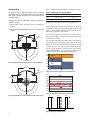
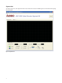
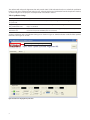
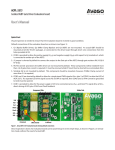
Selection of signal pairs for signal plotting
Virtual Oscilloscope
Figure 12. Device Monitoring tab with real-time encoder data display
The Zero Reset button allows the zero offset of the
encoder’s position data to be set. When the Zero Reset
button is clicked, the alignment kit sends a short HIGH
pulse of 10 ms to the Zero_RST input pin of the encoder.
to the software through the USB bus. With the samples
acquired, the software will calculate the frequency of the
signal and derive the encoder’s code wheel rotation speed
in RPM (Rotation per Minute).
Check the “MSB Invert” box if inverted counting is required.
When the “MSB Invert” box is checked, the alignment kit
will output a HIGH level on “MSBINV” pin and vice versa.
The time-base, signal amplitude scale (volt per division)
and offset can be set by the controls at the bottom of the
screen shown in Figure 12.
The software contains a virtual oscilloscope to plot
real-time encoder signals. Either of two signal-pairs can be
selected: AB Incremental signal pairs or Sine/Cosine signal
pairs. Signals are sampled at a 4000 Hz rate and transferred
Four trigger modes are support: None, Single, Normal and
Stopped. The trigger source is fixed to the A signal for AB
Incremental signal pairs and to the Sine signal for Sine/
Cosine signal pairs.
6