1
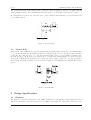
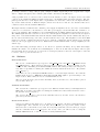
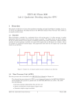
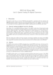
EECS 461 Winter 2009
Lab 4: Pulse Width Modulation and
Introduction to Simple Virtual Worlds
1
Overview
The purpose of this lab is to use the Pulse Width Modulation functions of the (enhanced) Modular Input/Output Subsystem (eMIOS). The PWM Submodule will be used to control the speed and direction
of the haptic wheel. In this lab, you will also design and implement two simple haptic virtual worlds, the
virtual spring and the virtual wall.
1.1
Enhanced Modular Input/Output Subsystem (eMIOS)
See Chapter 17 of the MPC5553 User’s Manual
The eMIOS module provides 24 channels with a versatile range of input and output functions. These functions range from simple digital I/O, to signal measurement abilities like pulse counting, edge accumulation,
and versions of quadrature decoding. In this lab we will be using the output PWM functionality of the
eMIOS system to control the motor of our haptic wheel.
The eMIOS module supports a number of pulse-width modulation modes: pulse width and frequency modulation (OPWFM), center aligned output pulse width modulation (OPWMC), pulse width modulation
(OPWM), and a number of buffered modes. The most practical for high-frequency output motor control is OPWFM. This requires a single MIOS channel and no external counter busses. A channel in this
mode operates by performing operations based on the comparision of the internal counter (incremented at a
prescaled eMIOS clock rate) to two data registers, A and B. When the internal counter reaches zero, through
reset or wrap-around, the channel output is set to the negation of the EDPOL bit. At the match of the
counter to the value in data register A, the channel output is set to the value of the EDPOL bit; on a match
with register B, the counter is reset to zero.
As an example, if EDPOL is cleared, the PWM signal will go high between counter values 0 and A. It will
go low between counter values A and B. Upon reaching B, the counter will reset to zero. Therefore, the
output signal will be high (A/B) percent of the time.
The resolution of data register A in determining our duty cycle varies greatly depending on the configuration
of the prescalers. As an example, if data register B is configured as 10, our only options for setting data
register A are 1 through 10, each setting resulting in 1/10th of the overall period. Because we require fine
control of the motor, duty cycle steps of 10% are much too coarse and are unacceptable. We will want to
set data register B to as large a number as possible, so we have very fine control of the duty cycle. However,
data register B also controls the PWM frequency. Therefore, the prescalers control the tradeoff between
frequency and resolution.
1.2
Virtual Spring
Figure 1 shows the puck attached to a reference point by a virtual spring with spring constant k. If the
puck is moved to either side of the reference point, the spring will exert a restoring force Fs = -kx that
EECS 461: Embedded Control Systems
1
Winter 2009
Lab 4
PWM and Simple Virtual Worlds
will accelerate the puck back toward the zero position (because the spring is “virtual,” we assume that its
relaxed length is equal to zero, and thus that the puck can move to either side of the reference point).
In our application, we use a motor and encoder to create a virtual torsional spring to rotate the wheel back
to a nominal position.
Figure 1: Virtual Spring
1.3
Virtual Wall
There are two major differences between a virtual spring and virtual wall. On one side of a virtual wall (x
> xo ), the disc should be freely spinning and the motor should apply no force to the wheel. Once the wheel
rotates into the other region (x < xo ), the motor should apply a force to oppose further penetration into
the wall. In order to allow the motor to spin freely on one side of the wall and apply force on the other side
of the wall, a simple if-then statement can be used. In order to apply a large force opposing penetration
into the wall, the spring constant, k, can be increased. Figure 2 below illustrates the virtual wall for linear
motion.
Figure 2: Virtual Wall
2
2.1
Design Specifications
Hardware
The interface board has connections to four eMIOS channels, zero through three. Each input is provided
with a two pin header. One pin is connected to an eMIOS output while the other pin is connected to 0 V,
EECS 461: Embedded Control Systems
2
Winter 2009
Lab 4
PWM and Simple Virtual Worlds
providing a reference voltage. The properly configured eMIOS output will provide a square wave output
with a configured frequency and a variable pulse width controlled by the MPC5553.
Using a parallel cable, a connection can be made from the interface board to the haptic devices. Over this
connection, the Channel 0 (MIOS 0) signal is delivered to an amplifier inside the haptic interface. The amplifier powers the motor of the haptic device. A quadrature encoder is also connected to the haptic interface,
as you have learned in Lab 2. With the simple connections to the motor and encoder, virtual worlds can be
constructed and controlled with the MPC5553.
The haptic interface available in lab contains a power supply, an amplifier, an encoder, a motor, and a DB-25
connector for connection to the interface board. The power supply converts 120 VAC into 24 VDC to be
used by the amplifier. The amplifier receives a PWM signal from eMIOS Channel 0 and drives the motor.
The PWM signal switches between zero and 3.3 V, and though the amplifier is bi-directional, the input is
uni-polar so 3.3V results in full forward current and 0V results in full reverse current. With a 50% duty cycle,
the two directions will average each other out and result in 0 net torque. The amplifier receives the PWM
signal as a current command and drives the motor with the commanded current which is proportionally
related to the torque applied by the motor. This scheme is much different than a voltage amplifier (see the
class notes).
Note that when using your haptic wheel, do not allow it to spin uncontrollably. It is possible that simple
mistakes in software, a non-existent motor PWM signal, or other errors will cause the haptic wheel to spin
uncontrollably. If it does spin out of control, the red emergency switch on the side of the haptic box should
be used to remove power from the motor.
2.2
Software
mios.h and mios.c
The mios.h contains function prototypes for init MIOS clock, init PWM, set PWMPeriod and
set PWMDutyCycle. These functions will deal with configuring the counter prescalar for the
eMIOS module, initializing an individual PWM channel, and setting its duty cycle and period.
You will be responsible for writing the definitions for these functions in the mios.c file (rename
mios template.c).
You will need to use your FQD and PWM software to control the haptic interface. Note that the
PWM output needs to be limited to 35 to 65 percent duty cycle to prevent damage to the
haptic devices. These values are set as constants within mios.h.
The mios.h file should be placed in the include/ directory and the mios.c file should be placed
in your lib/ directory.
worlds.h and worlds.c
The worlds.h file contains the prototypes for the different virtual worlds you will implement in
EECS 461. You will be responsible for writing the definitions for these functions in the worlds.c
file (rename worlds template.c).
The worlds.h file should be placed in the include/ directory and the worlds.c file should be
placed in your lib/ directory.
motor.h and motor.c
You need to make a C file called motor.c from the motor template.c file that contains the function
outputTorque. Place this file in your lib/ directory. The prototypes and details of these
functions can be found in the motor.h file. It is very important that you follow these prototypes
and the comments in the motor template.c file closely. Since you will now also be using the
MIOS1 PWM functions, be sure to add the necessary #include lines.
EECS 461: Embedded Control Systems
3
Winter 2009
Lab 4
PWM and Simple Virtual Worlds
Extreme torque values will cause the haptic device to accelerate very quickly, potentially causing
harm to the system. Because of this, within this function, limit the actual applied torque
to a range from -825 N-mm to 825 N-mm.
lab4.c
Create the main program for you lab from the lab4 template.c. Most of the initializations and
the necessary #include lines are done for you.
Makefile
A makefile has been provided to you. Place this file in your lab4/ directory for proper compilation.
3
Pre-Lab Assignment
Pre-lab questions must be done individually and handed in at the start of your lab section. You must also,
with your partner, design an initial version of your software before you come to your lab section. Your
software does not need to be completely debugged, but obviously more debugging before coming to lab means
less time you will spend in the lab.
You need to make a C file called mios.c. This file should be placed in your lib/ directory. The file should
contain four functions named init MIOS clock, init PWM, set PWMPeriod and set PWMDutyCycle. Each of
the PWM functions will accept an integer, pwmModule, whose value ranges from zero to three corresponding
to the eMIOS channel available on the interface board. The prototypes of these functions can be found in
the mios.h header file.
1. The init MIOS clock function needs to configure the eMIOS module to maintain the highest frequency
possible. Since this determines the base counter clock frequency for the module, it will be required in
order to establish any PWM outputs. The system clock frequency, fSY S , is 40 megahertz. Complete
this function.
2. Using the EMIOS.MCR prescalar you chose in the previous question,what is the highest-frequency
PWM output we can establish and still control duty cycle to a resolution of 0.5% ? What
is the maximum attainable resolution of a 20 kHz PWM output?
3. The init PWM function configures the input eMIOS channel for OPWFM. Complete this function
where indicated.
4. The set PWMPeriod function will accept a 24-bit number (passed as a 32-bit integer), newPeriod,
indicating the new period to be used for the PWM output. newPeriod does not represent an actual
unit of time. Instead, newPeriod represents the number of counts by the eMIOS module clock for each
period.Complete this function.
5. The set PWMDutyCycle function will accept a floating-point number, dutyCycle, corresponding to the
new duty cycle of the OPWFM. The value of dutyCycle will represent a fraction of the total “on-time”
of the output and range from zero to 1. Complete this function.
6. Relating various physical quantities to settings used in software is important for being able to effectively
design haptic worlds. Through testing, one can determine the relationship between torque and duty
cycle for a motor. For the motor we are using, the equation can be approximated as the following:
Torque at the motor (in N-m) = 1.942 * (duty cycle - 0.5)
In order to get an idea for what these units of torque represent,write some simple code so as to
output 200 N-mm of torque at the wheel. Be careful so as to not allow the wheel to accelerate
out of control. This can be done by either being sure to hold the haptic device, or (preferably) by
writing code so that if the device rotates out of a certain range, it stops.
EECS 461: Embedded Control Systems
4
Winter 2009
Lab 4
PWM and Simple Virtual Worlds
7. Create the function outputTorque within motor.c. This function receives torque desired on the
haptic wheel, in N-mm, and computes and sets the PWM duty cycle.
8. Write a file worlds.c in which you implement the functions virtualWall and virtualSpring
as specified in the worlds.h file. Place this file in the lib/ directory. Implement your virtual wall
so as to give a resistance of 500 N-mm per degree of wheel movement into the wall. For the virtual
spring, us a spring constant of 10 N-mm per degree. Use the outputTorque function in the motor.c
file to apply the computed torque on the haptic wheel.
9. Be sure to hand in your completed mios.c, motor.c, worlds.c files.
4
In-Lab Assignment
1. Write a program called lab4.c from the lab4 template.c. The main function calls the init EECS461(4)
function for Lab 4 to initialize the floating point unit and to set the processor speed. The lab4.c file
then calls init MIOS clock and init PWM to initialize the module prescalers and initial PWM period
for the output on Channel 0. The quadrature decoding function is also initialized for later use in the
lab. The lab4.c file should be placed in the lab4/ directory.
2. Compile and debug your lab4.c program using the makefile, using the command gmake.
3. Power up the board and use the P&E Debugger to download the lab4.elf file to the board. Run your
program and verify that the PWM output operates at 20 kHz and has an initial duty cycle of 50
percent.
4. Connect the haptic wheel to the interface board. Using your QADC functions developed in lab 3,
change the lab4.c file so that it reads a value from a QADC input and translates it to a duty cycle on
the PWM output. Scale the input values of the eQADC such that the duty cycle you output is can
attain a maximum of 65 % and a minimum of 35%. Verify that the PWM output is what it should be
by connecting the PWM pin out to an oscilloscope. A test loop labeled “MIOS 0” is provided on the
upper right corner of interface board. Note how the motor reacts to the PWM signals generated.
5. Change the PWM frequency to 1 kHz and recompile your program. Output a constant 0 N-mm torque
and note how the motor reacts to the PWM signal. Change the PWM frequency back to 20 KHz
before continuing to the next step.
6. Run your code to determine what 200 N-mm of torque at the wheel feels like. Be sure to hold on to
the wheel before you start your code. If you want, you can try some other values as well.
7. Test and debug your virtual spring, first by monitoring the PWM signal and then by observing the
behavior of the wheel. Alter the spring constant and observe how the system changes as you do this.
8. Test and debug your virtual wall. Try different values of the spring constant, k. On the oscilloscope,
you should notice that the constant 50% duty cycle observed when outside the wall changes only when
inside the wall. Determine the spring constant that yields the “best” virtual wall, in terms of duty
cycle/encoder ticks and torque/degrees at the wheel. What criteria are you using to determine the
“best” wall?
9. Choose a very large value for the virtual wall’s spring constant. Note the reaction of the system.
5
Post-Lab Assignment
1. A high-frequency pulse-width modulated signal with 50% duty cycle sent to the amplifier translates
into a motionless motor. The 50% duty cycle is necessary because our motor is set up to use one-wire
signaling.Why is the high frequency necessary? (Think of the frequency response characteristics
of the motor.)
EECS 461: Embedded Control Systems
5
Winter 2009
Lab 4
PWM and Simple Virtual Worlds
2. What is a physiological reason for using PWM signals above 20 kHz?
3. What effect does the value of the EDPOL bit in the eMIOS Channel Control Register
have on the PWM output? How could we use the functionality this bit offers in the lab?
4. What happens when the spring constant of the virtual wall is increased to a very large
number? Why does this occur? Your answer should consider the differences between continuoustime systems and discrete-time systems.
5. Suppose we wished to implement a model that required a velocity measurement.Give an equation for
estimating velocity from successive position measurements. What additional information
is required that you could not obtain in Lab 4?
6. Include well-documented copies of your lab4.c, mios.c, motor.c and worlds.c files.
If you have comments that you feel would help improve the clarity or direction of this assignment, please
include them following your postlab solutions.
EECS 461: Embedded Control Systems
6
Winter 2009