1
Telephone number
Setting of operating parameters with a computer
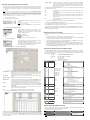
We recommend using program CG5config for setting up module CG5 operating parameters. This will allow
setting parameters of the equipment quicker and easier. The program can be found on website www.trikdis.lt.
1.
Connect the module CG5 with computer USB port. Computer must have appropriate USB drivers
installed.
Note: If the module CG5 is connected to a MS Windows OS computer for the first time a new Found New Hardware Wizard
window should open for installing new USB drivers. This window means that a USB driver has to be installed in order to
connect to the module CG5 properly. Download the USB driver file USB_COM.inf from website www.trikdis.lt. In the wizard
window select the function Yes, this time only and press the button Next. When a new window Please choose your search
and installation options will open, press the button Browse and select the place where the file USB_COM.inf was saved.
Follow the remaining wizard instructions to finish USB driver installation.
2.
Start the program CG5config.
3.
Select the program directory Settings.
In the drop-down list Port select the port to which the module is
connected.
Note: specific port to which the device is connected is shown only when
the device is properly connected.
In the drop-down list Language select the desired software
language.
4.
Press the button Connect/Disconnect [F2/F8]
When the module CG5 is connected to a computer, module LED
indicator Power should flash green and yellow in turn, and
CG5config status bar should indicate connection status
Connected. Further information about the connected module
should be displayed in status bar:
6.
By checking boxes below the GSM numbers, you can choose how each recipient will be alerted and which type
of messages will be sent to them:
SMS
SMS messages will be sent when appropriate input circuit is broken (box E) and
restored (box R),
Call
A call will be made to alert that appropriate input circuit is broken (box E) and
restored (box R),
LP
SMS messages will be sent when informing about disturbances in power supply chain,
Test
Module shall send test messages to the recipient according to the time period set in
the field Test every.
ACK
Module CG5 shall send confirmation about command execution to the recipient who
has sent the command.
8.
Press the button Save [F6] and set configuration will be uploaded to Module CG5.
9.
Press the button Disconnect [F8] and unplug USB cable.
A set configuration file can be created with extention .gst and saved in the computer by the pressing the
button Save [F5]. The file as a templet can be used in the future.
If you need to restore Module CG5 default parameters, press the button Restore [F11] and press the button
Confirm when request window newly opens. Module CG5 default operating parameters can be restored any
time before unplugging the USB cable.
Module firmware version updating
Module type
When the manufacturer adds new features to the Module CG5, firmware of the previously bought CG5 can be
updated:
Module serial number
1.
Download the latest CG5_xxx.prg update file from the website www.trikdis.lt.
2.
Connect the Module CG5 to a computer and start the CG5config program. Select the directory Firmware
in program CG5config and select the downloaded update file CG5_xxx.prg.
Enter your access code and press the button OK in the opened
window Access code (default access code is 1234).
3.
Firmware update will start after pressing the button Start [F9]. Wait until Progress bar reaches 100%,
then press the button Disconnect [F8] and unplug the USB cable.
If you want CG5config to remember your access code check the
box Remember. Then the Access code window will not open,
when connecting to the module for the next time.
4.
Plug the USB cable back in and press one by one the buttons Connect [F2] and Read [F7]. The new
version of Module firmware will be displayed in status bar of the program CG5config. Now you can set
additionally configuration according to the manner described in previous chapter. If you don’t need this,
press the button Disconnect [F7] and unplug USB cable.
Firmware version installed in the module
5.
Enter the GSM numbers of mobile phones, to which the module will send SMS
messages and/or will make calls. Module parameters can be set or the state of
output OUT1 can be controlled by sending SMS messages only from phones having
these numbers. GSM numbers should be entered with international country code
without the “+” (plus) sign.
Press the button Read [F7]
Set the following parameters in the directory SMS reporting.
Setting of operating parameters with SMS messages
Some Module operating parameters can be set by sending SMS messages from authorised phone to the GSM
number of the SIM card inserted in the Module. If function ACK for confirming SMS commands is set, Module
will send back SMS messages with confirmations that: COMMAND OK, Wrong COMMAND!!!, Wrong
PASSWORD!!!, Wrong DATA!!!.
-
SMS syntax:
<Command>space<Password>spaces<Data>
For example:
SETN 1234 PHONE1=+37068700000
Here:
SETN – command
1234 – password
PHONE1=+37068700000 – data
Note: All commands in SMS message have to be written in capital letters.
Ser No
1
Command
SETL
Content
ENG
RUS
LIT
2
SETN
PHONE1=+370xxx
PHONE2=+370xxx
PHONE3=+370xxx
PHONE4=+370xxx
Access code
Default access code 1234 must be changed to one known by you and other
authorised persons only. This code is used for setting operating parameters of the
module and/or to control the state of output OUT1 with SMS messages. When
changing the password, enter a desired four-digit sequence.
Account name
If desired, enter the name of the object. Account name will be included in SMS
messages.
SMS text encoding
Select the format of SMS text encoding in the drop-down list.
Operation mode
Select the desired module CG5 operating mode: either 24 h or Control panel. If there
is set NO or NC type, all five inputs will respectively become either NO or NC. If there
is set EOL type, inputs IN1...IN4 will become EOL=2.2kΩ and the input MCI – NC.
Output
Select the desired output OUT1 operating mode. If you connect a siren to the output,
select the option Siren. If you would like that after receiving a command with SMS
message, the module would change the state of its output, select the option Remote
control by SMS.
Test time
Enter a desired time period according to which the module will send a periodic
message with text entered in the row Test.
Call
When event occurs module will call to User pre-set number of times.
7.
PHONE1=DEL
PHONE2=DEL
PHONE3=DEL
PHONE4=DEL
3
SETE
TEST
ACK
CALL
SMS
4
TXTA
5
TXTE
<Text>
Z1=<Text>
........
Z6=<Text>
6
TXTR
Z1=<Text>
........
Z6=<Text>
Choose the directory SMS reporting and set desirable parameters used for reporting.
7
TIME
8
PSW
<Time>
New PSW
9
RESET
10
INFO
11
SLEEP
Meaning
Setting of language:
English
Russian
Lithuanian
For example: SETL 1234 ENG
Entering of recipients’ telephone numbers:
st
1 GSM number
2nd GSM number
3rd GSM number
th
4 GSM number
For example: SETN 1234 PHONE1=+37068700000
Deleting of recipients’ telephone numbers:
st
1 GSM number
2nd GSM number
rd
3 GSM number
4th GSM number
For example: SETN 1234 PHONE1=DEL
Distributing of messages by their type:
Enabling sending of Test message
Enabling sending of acknowledgements about
command executing
Enabling calling if event happens
Enabling SMS sending if event happens
For example: SETE 1234 PHONE1=... TEST=ON ACK=ON
CALL=OFF SMS=ON
Setting of object name:
For example: TXTA 1234 Object name
Customising of SMS with alarm text:
Z1...Z6 – input number
For example: TXTE 1234 Z1=ALARM in Zone1
Customising of SMS with restore text:
Z1...Z6 – input number
For example: TXTR 1234 Z1=Restore Zone1
Setting of internal clock:
For example: TIME 1234 YYYY/MM/DD,12:00:00
Setting of password:
New password (4 digit)
For example: PSW 1234 4321
Module reset:
For example: RESET 1234
Request for info about module state:
For example: INFO 1234
Stop sending of SMS that have been unsent till RESET
command:
For example: SLEEP 1234
Remote switching of PGM output OUT1
In order to change state of output OUT1 you need to send an SMS message to the SIM card GSM number of the
Module. Examples of SMS messages are provided in the table below.
Note: All commands have to be written in capital letters.
Zone alarm/restore events can be described with a text. Enter your texts in appropriate text-boxes. When input
circuit is disturbed, an SMS message will be sent with text from the appropriate text-box Event message. When
input circuit is restored – from the text-box Restore message. Texts which describe events in power supply
chain can be entered in the box LP. There can be entered desirable text which will be included in periodic
message in the box Test.
SMS syntax
Meaning
Pataba
OUTPUT 1234 ON
Output turns to position ON (circuit closes)
1234 – default password. Instead
OUTPUT 1234 OFF
Output turns to position OFF (circuit opens)
of this, enter your.
OUTPUT 1234 PULSE=005
Output turns to position ON for entered time (sec)
Note: Output state can be switched only when operating mode of the Module is set as 24h and output operating mode is set
as Remote control by SMS.