1
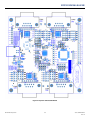
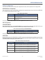
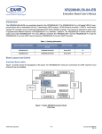
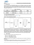
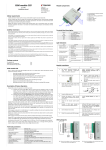
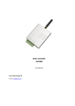
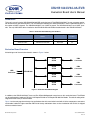
XR21B1424IV64-0A-EVB
Evaluation Board User’s Manual
Introduction
This user’s manual is for the XR21B1424IV64-0A-EVB evaluation board. The XR21B1424IV64-F shares a common evaluation board with the XR21B1422IL40-F. The main difference between the XR21B1424IV64-F and the XR21B1422IL40-F is
the number of UART channels. The XR21B1424IV64-F has 4 UART channels. The XR21B1422IL40-F has 2 UART channels. The only USB UART device installed on the XR21B1424IV64-0A-EVB evaluation board is the XR21B1424IV64-F.
Table 1: Evaluation Board Ordering Part Numbers
Device Ordering Part Number
Evaluation Board Ordering Part
Number
Device Package
Device
Location
XR21B1424IV64-F
XR21B1424IV64-0A-EVB
64-pin LQFP
U7
XR21B1422IL40-F
XR21B1422IL40-0A-EVB
40-pin QFN
U6
Evaluation Board Overview
A block diagram of the evaluation board is shown in Figure 1 below.
USB
Connector
SP338
SP339
DB9
Connector
SP338
SP339
DB9
Connector
SP338
SP339
DB9
Connector
SP338
SP339
DB9
Connector
XR21B1424
Figure 1: Evaluation Board Block Diagram
In addition to the XR21B1424IV64-F, there are Exar SP339 Multiprotocol transceivers on this evaluation board. The SP339
can be configured for Loopback, RS-232, Half-Duplex RS-485 or Full-Duplex RS-485/422 Modes. The default setting when
shipped from the factory is RS-232 mode.
Figure 2 on the next page show the top view and bottom view of the evaluation board with all of the components, connectors
and headers labeled. A higher resolution PDF file for the top and bottom views are also included on the CD that is shipped
with the evaluation board.
© 2014 Exar Corporation
1/6
exar.com/XR21B1421
Rev 1A
XR21B1424IV64-0A-EVB
Figure 2: Top View of Evaluation Board
© 2014 Exar Corporation
2/6
exar.com/XR21B1424
Rev 1A
XR21B1424IV64-0A-EVB
Hardware Configurations
This sections describes the default settings when shipped from the factory and the requirements for changing modes.
XR21B1424 Power Configurations
When shipped from the factory, the XR21B1424 is configured for bus-powered mode and uses the 5V from the USB VBUS
pin. The default jumper settings are shown in Table 2.
Table 2: Default Jumper Settings
Jumper Setting
Description
J27 - 1 & 2
Connects 5V from VBUS to VCC_REG (pin 13). A regulated 3.3V output will be available on the VCC pin (pin 12).
J35 - 1 & 2
Connects regulated 3.3V from VCC pin to VIO. The output voltage of the UART/GPIO
pins will be 3.3V.
If not using the 5V from VBUS, an external 3.3V can be supplied to VCC_REG via J27 pin 2.
GPIO Configurations
GPIOA0/RIA#/RWKA#
When shipped from the factory, the GPIOA0/RIA#/RWKA# pin is connected to the push-button switch (SW1). SW1 can be
used to test the remote wake-up functionality. The default jumper settings are shown in Table 3.
Table 3: Default Jumper Setting for GPIOA0/RIA#/RWKA#
Jumper Setting
J25 - 2 & 3
Description
GPIO0/RI#/RWK# connected to SW1. Can be used for remote wake-up.
Changing the header to J25 1&2 will connect the GPIOA0/RIA#/RWKA# pin to the SP338/SP339 transceiver.
GPIO0-GPIO5
Besides GPIO0 of channel A, GPIO0-GPIO5 of all UART channels are connected directly to the SP339 transceiver. There
are headers installed for easy access to these signals. If testing with these pins without the SP339 transceiver, the SP339
should be disabled by removing the jumpers listed in Table 4.
Table 4: Default setting for SP339 Transceiver
© 2014 Exar Corporation
Jumper Setting
Description
J5 - 7 &8
USB_STAT2 enables/disables the SP339 transceiver for channel A. When this jumper is
removed, the internal pull-down resistor for the ENABLE pin disables the SP339.
J10 - 7 &8
USB_STAT2 enables/disables the SP339 transceiver for channel B.When this jumper is
removed, the internal pull-down resistor for the ENABLE pin disables the SP339.
J11 - 7 &8
USB_STAT2 enables/disables the SP339 transceiver for channel C.When this jumper is
removed, the internal pull-down resistor for the ENABLE pin disables the SP339.
J20 - 7 &8
USB_STAT2 enables/disables the SP339 transceiver for channel D.When this jumper is
removed, the internal pull-down resistor for the ENABLE pin disables the SP339.
3/6
exar.com/XR21B1424
Rev 1A
XR21B1424IV64-0A-EVB
GPIO6/CLK
When shipped from the factory, the GPIO6/CLK pin is floating. If using this pin as a CLK function, the signal can be captured via the J31 header. If using this pin to control the MODE0 pin of the SP339, install jumpers for the appropriate channels listed in Table 5. The software driver/application will need to control the state of this pin.
Table 5: Default Jumper Setting for GPIO6/CLK
Jumper Setting
Description
J5 - 1& 2
Not installed. GPIOA6/CLKA is not connected to the MODE0 pin of the SP339.
J10 - 1& 2
Not installed. GPIOB6/CLKB is not connected to the MODE0 pin of the SP339.
J11 - 1& 2
Not installed. GPIOC6/CLKC is not connected to the MODE0 pin of the SP339.
J20 - 1& 2
Not installed. GPIOD6/CLKD is not connected to the MODE0 pin of the SP339.
GPIO7/RS485
When shipped from the factory, the GPIO7/RS485 pin is floating. This pin can be used to control the DIR1 pin of the SP339
when the SP339 is configured for half-duplex RS-485 mode. If using this pin to control the DIR1 pin of the SP339, install
jumpers for the appropriate channels listed in Table 6. The software driver/application will need to enable the half-duplex
direction control feature for this pin.
Table 6: Default Jumper Setting for GPIO7/RS485
Jumper Setting
Description
J3 - 1& 2
Not installed. GPIOA7/RS485A is not connected to the DIR1 pin of the SP339.
J10 - 1& 2
Not installed. GPIOB7/RS485B is not connected to the DIR1 pin of the SP339.
J11 - 1& 2
Not installed. GPIOC7/RS485C is not connected to the DIR1 pin of the SP339.
J20 - 1& 2
Not installed. GPIOD7/RS485D is not connected to the DIR1 pin of the SP339.
GPIO8/TXT
When shipped from the factory, the GPIO8/TXT pin is floating. This pin can be used to control the MODE1 pin of the SP339.
If using this pin to control the MODE1 pin of the SP339, install jumpers for the appropriate channels listed in Table 7. The
software driver/application will need to control the state of this pin.
Table 7: Default Jumper Setting for GPIO8/TXT
Jumper Setting
© 2014 Exar Corporation
Description
J5 - 3 & 4
Not installed. GPIOA8/TXTA is not connected to the MODE1 pin of the SP339.
J10 - 3 & 4
Not installed. GPIOB8/TXTB is not connected to the MODE1 pin of the SP339.
J11 - 3 & 4
Not installed. GPIOC8/TXTC is not connected to the MODE1 pin of the SP339.
J20 - 3 & 4
Not installed. GPIOD8/TXTD is not connected to the MODE1 pin of the SP339.
4/6
exar.com/XR21B1424
Rev 1A
XR21B1424IV64-0A-EVB
GPIO9/RXT
When shipped from the factory, the GPIO9/RXT pin is floating. This pin can be used to control the MODE2 pin of the
SP339. If using this pin to control the MODE2 pin of the SP339, install jumpers for the appropriate channels listed in
Table 8. The software driver/application will need to control the state of this pin.
Table 8: Default Jumper Setting for GPIO9/RXT
Jumper Setting
Description
J5 - 5 & 6
Not installed. GPIOA9/RXTA is not connected to the MODE2 pin of the SP339.
J10 - 5 & 6
Not installed. GPIOB9/RXTB is not connected to the MODE2 pin of the SP339.
J11 - 5 & 6
Not installed. GPIOC9/RXTC is not connected to the MODE2 pin of the SP339.
J20 - 5 & 6
Not installed. GPIOD9/RXTD is not connected to the MODE2 pin of the SP339.
SP338/SP339 Mode Selection
When shipped from the factory, the SP338/SP339 transceivers are configured in the RS-232 mode. Table 9 shows the RS232 settings for the SP339.
Table 9: SP339 RS-232 Mode Pin Configurations
Mode
Configuration
MODE0
1
MODE1
0
MODE2
0
There are 2 sets of headers for each UART channel for configuring the mode of the SP339 transceiver. For example, channel A uses J5 and J4. For the RS-232 mode, there is a jumper from J5 pin 2 to J4 pin 1. Refer to the table in the schematic
or the SP339 datasheet for the different configurations.
By default, the ENABLE of the SP339 transceiver is controlled by the USB_STAT2 pin of the XR21B1424.
Half-duplex, Full-Duplex and Mixed Duplex RS-485/422 modes
In the RS-485 half-duplex, full-duplex and mixed duplex modes, the DIR1 pin of the SP338/SP339 enables or disables the
RS-485/422 line drivers. The DIR1 pin can be controlled by the XR21B1424 using the GPIO7/RS485 or GPIO5/RTS#/
RS485 output pins. The GPIO7/RS485 or GPIO5/RTS#/RS485 pin can be selected via J21. Refer to the datasheet for
details for selecting and enabling the Automatic Transceiver Enable feature for the GPIO7/RS485 or GPIO5/RTS#/RS485
pins.
Software and Technical Support
Software drivers and test applications should be included in the CD that accompanies the evaluation board. Send any questions that you may have to [email protected].
© 2014 Exar Corporation
5/6
exar.com/XR21B1424
Rev 1A
XR21B1424IV64-0A-EVB
Revision History
Revision
Date
1A
April 2014
Description
Initial release.
For Further Assistance:
Email: [email protected]
Exar Technical Documentation: http://www.exar.com/techdoc/
Exar Corporation Headquarters and Sales Offices
48720 Kato Road
Tel: +1 (510) 668-7000
Fremont, CA 95438 - USA
Fax: +1 (510) 668-7001
NOTICE
EXAR Corporation reserves the right to make changes to the products contained in this publication in order to improve design, performance or reliability. EXAR Corporation
assumes no responsibility for the use of any circuits described herein, conveys no license under any patent or other right, and makes no representation that the circuits are free
of patent infringement. Charts and schedules contained herein are only for illustration purposes and may vary depending upon a user’s specific application. While the information
in this publication has been carefully checked; no responsibility, however, is assumed for inaccuracies.
EXAR Corporation does not recommend the use of any of its products in life support applications where the failure or malfunction of the product can reasonably be expected to
cause failure of the life support system or to significantly affect its safety or effectiveness. Products are not authorized for use in such applications unless EXAR Corporation
receives, in writing, assurances to its satisfaction that: (a) the risk of injury or damage has been minimized; (b) the user assumes all such risks; (c) potential liability of EXAR Corporation is adequately protected under the circumstances.
Reproduction, in part or whole, without the prior written consent of EXAR Corporation is prohibited.
© 2014 Exar Corporation
6/6
exar.com/XR21B1424
Rev 1A