1
No. CP–SS–1814E
Single Loop Controller
SDC15
■ Features
The DigitroniK SDC15 is a 48 x 48mm compact digital
controller featuring group multi-range inputs and PID
control system using new algorithms "Rationaloop PID
(Ra-Pid)" and "Just-FiTTER".
Up to two control output points (this number of points
may vary depending on the model) can be used, which
are selectable from the relay contact, voltage pulse, and
current.
Two kinds of mounting methods are provided, panel
mounting type and socket mounting type.
Additionally, this controller is compliant to the CE marking.
• Compact body with a depth of 60 mm.
The mask of the front panel is also only 2 mm thick.
• The accuracy is ±0.5%FS.
• The input type can be changed among the thermocouple
input group, RTD group, and linear group.
• The control method can be selected from any of the ON/
OFF control, PID control using "Rationaloop PID (RaPid) + Just-FiTTER", and self-tuning.
• The heat and cool control can be achieved using two control output points and event outputs.
• 18 kinds of operations, such as set (SP) value selection,
RUN/READY selection, and latch cancellation, etc. can
be set using two external switch input points.
• The process variable (PV) value can be corrected.
• The controller is applicable to the communication (3-wire
RS-485).
• Up to eight points can be registered for the parameter
keys, ensuring easy operation.
• Use of "mode" key ensures easy operation, RUN/
READY, AUTO/MANUAL, and SP selections, and EVrelay latch cancellation.
• Up to three event output points are provided.
In addition to temperature events, such as PV, DEV, and
SP, status events, such as CT heater burnout, over-current, and loop diagnosis can also be set.
• The controller is compliant to the CE marking
(safety standards EN61010-1 and EN61326-1).
• Use of personal computer loader (optional unit) makes it
possible to easily perform various settings, such as setup
and parameter setting.
• Use of personal computer loader makes it possible to easily achieve the data logging from single unit to up to eight
units.
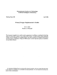
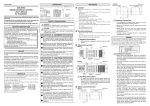
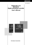
■ Basic Function Block of SDC15
Process variable (PV) input
External switch input
(2 points)
• 11 kinds of thermocouple selections
(19 kinds of ranges)
2 kinds of RTD selections
(14 kinds of ranges)
6 kinds of DC voltage/current input
selections
• Current (PV) value correction
• Current (PV) value filter
• Current (PV) value ratio
• Set (SP) value, 4 kinds of selections
• RUN/READY selection
• Latch cancellation, etc., 18 kinds
• Relay contact
• Voltage pulse output (For SSR drive)
• Current output
Above outputs are combined.
Control (MV) output
(2 points)
Control operation
• PV upper limit, lower limit, upper/lower limit
• Deviation upper limit, lower limit, upper/lower limit
• Any of ON/OFF control,
self-tuning, and PID control
is selected.
• Direct/Reverse action
• Heat/Cool operation
• SP upper limit, lower limit, upper/lower limit
• MV upper limit, lower limit, upper/lower limit
• Heater burnout/Over-current
• EV functions, such as loop diagnosis
• Control output can be allocated.
Event output
(3 points)
• Personal computer loader
Loader communication
Current transformer input
(2 points)
Communication input/output
• RS-485 (3-wire)
Power supply
85 to 264Vac, 24Vdc *
1
Units marked an asterisk (*) will be available in the near future.
■ Specifications
PV input
Input type
Thermocouple, RTD, DC current, DC voltage (Selected by model. See Table 1.)
Sampling time
0.5s
Process variable (PV) -1999 to +9999 or -199.9 to +999.9
correction
Input bias current
Thermocouple input:
RTD input:
DC voltage input:
0.2µA or less (under standard conditions)
Approx. 1mA (flowed from A-terminal)
0 - 1V range
:1µA or less
0 - 5V, 1 - 5V range
:3.5µA or less
0 - 10V range
:7µA or less
Effect of wiring
resistance
Thermocouple input:
RTD input:
DC voltage input:
0.2µV/Ω or less
±0.05%FS/Ω or less
0 - 1V range
0 - 5V, 1 - 5V range
0 - 10V range
Thermocouple input
RTD input
Upscale + alarm display (AL01)
RTD burnout
:Upscale + alarm display (AL01)
A-wire burnout
:Upscale + alarm display (AL01)
B-wire burnout
:Upscale + alarm display (AL01, AL03)
C-wire burnout
:Upscale + alarm display (AL01, AL03)
2- or 3-wire burnout
:Upscale + alarm display (AL01, AL03)
A- and B-wire short-circuit :Downscale + alarm display (AL02)
A- and C-wire short-circuit :Downscale + alarm display (AL02)
DC voltage input
:Downscale + alarm display (AL02)
However, a voltage input ranging from 0 to 10V cannot
be detected.
DC current input
:Downscale + alarm display (AL02)
However, a current input ranging from 0 to 20mA
cannot be detected.
Display at burnout
PV, SP indication method 4-digit, 7-segment LED (PV: Upper green display, SP: Lower orange display)
Number of setting points Max. 4 points
<, , or
Setting range
See Table 1.
Indication accuracy
±0.5%FS±1 digit
In the negative area of the thermocouple, the accuracy is ±1%FS±1 digit (at an ambient temperature of
23±2°C).
<
Setting method
<
Indications
and setting
:1µV/Ω or less
:3.5µV/Ω or less
:7µV/Ω or less
key operation at each digit
Indication range
See Table 1.
Indication and
setting units
Thermocouple input
:1°C
RTD input
:1°C, 0.1°C (depending on the type of input)
DC voltage input/DC current input (programmable range): 1, 0.1, 0.01, 0.001
Settling value (SP)
Lower limit Lower limit value of range to upper limit value of setting value (SP) limit
limit
upper limit
Function display method
Digital 4-digit, 7-segment LED indication (Common to the PV display, displayed in green)
Status indication
EV1, EV2, EV3: Red LED lamp indication
0T1, 0T2 (control output), RDY (READY), MAN (power): Green LED lamp indication
Display selection
Process variable (PV), Setting value (SP), Control output value, Heater current value, Time event remaining
time, SP No.
Key lock
Selected from the following three methods:
• Key lock is activated in all modes.
• Operable only for operation indications SP/EV/UF and parameter setting mode/SP/event.
• Operable only for operation indications SP/EV/UF.
Password
The data is protected by setting the password.
Control output Output type
Lower limit value of setting value (SP) limit to upper limit value of range
Relay contact
Voltage pulse (For SSR drive)
Current
Control method
Selected from the following three methods:
• ON/OFF control
• Control with fixed PID value (PID control using "Rationaloop PID (Ra-Pid)" and "Just-FiTTER")
• Self-tuning
Output rating
Output rating:
(Control output NO side)
250Vac/30Vdc, 3A (resistive load)
(Control output NC side)
250Vac/30Vdc, 1A (resistive load)
Service life:
50,000 cycles or more on NO side
100,000 cycles or more on NC side
Min. opening/closing specifications:
5V, 100mA
Cycle time (s)
PID control
Open voltage: 19Vdc±15%
Internal resistance: 82Ω±0.5%
Allowable current: Max. 24mAdc
Leak current at OFF: Max. 100µA
5 to 120
0.1, 0.25, 0.5, 1 to 120
Proportional band (%FS)
0.1 to 999.9
Integral time (s)
0 to 9999 (PD operation when I = 0)
Derivative time (s)
0 to 9999 (PI operation when D = 0)
Manual set (%)
-10.0 to 110.0 (only when I = 0)
2
Output type:
0 to 20mAdc or 4 to 20mAdc
Allowable load resistance:
Max. 600Ω
Output accuracy: ±0.5%FS
(However, 0 to 1mA ±1%FS)
–
Control output Just-FiTTER
ON/OFF control
Overshoot suppression coefficient 0 to 100
Operation clearance (°C)
0 to 9999 or 0.0 to 999.9
Control operation selection Direct action or reverse action
RUN/READY selection
Selected with the RDY key on the front panel or external contact input (In READY mode: Control output OFF)
Heat/Cool control selection Control output and event output
External
contact
(digital input)
Number of inputs
2 points
Function
Up to four kinds of setting value (SP) selections, RUN/READY selection, AUTO/MANUAL section, Auto tuning
stop/start, Self-turning disable/enable, Control action Direct/Reverse selection, SP ramp enable/disable, PV
value hold, Max. PV value hold, Min. PV value hold, Timer start/stop, All DO latch cancellation
Input rating
Non-voltage contact or open collector
Min. detection holding time 1s or longer
Allowable ON contact Max. 250Ω
resistance
Allowable OFF
contact resistance
Min.100kΩ
Allowable ON-state
residual voltage
Max. 1.0V
Open terminal voltage 5.5Vdc±1V
ON terminal voltage
Event
Approx. 7.5mA (at short-circuit), Approx. 5.0mA (at contact resistance of 250Ω)
Number of output points 0 to 3 points (depending on the model)
Number of internal
event settings
Up to 5 settings
Event type
PV high limit
● shows that the ON/
OFF is changed at
this value.
Direct action
HYS
shows that the ON/
OFF is changed at
a point that "1U" is
added to this value.
PV low limit
Reverse action
ON
ON
Direct action
ON
HYS
Main setting
Main setting
PV
HYS
HYS
Main setting
PV
PV high/low limit
ON
ON
HYS
Sub-setting
Main setting
Direct action
HYS
HYS
ON
ON
HYS
HYS
ON
PV
PV
ON
Direct action
ON
ON
HYS
Main setting
ON
HYS
ON
HYS
ON
Main setting
Direct action
HYS
HYS
Sub-setting
HYS
MV
HYS
Main setting
HYS
Main setting
HYS
Main setting
ON
HYS
ON
Main setting
HYS
Sub-setting
MV
Heater short-circuit
HYS
Sub-setting
CT at output ON
3
ON
MV
Reverse action
ON
Reverse action
Sub-setting
MV
Sub-setting
CT at output ON
HYS
MV
HYS
Heater burnout/Over-current
ON
Main setting
Direct action
ON
ON
Main setting
Direct action
HYS
MV high/low limit
Reverse action
HYS
ON
ON
MV
SP
Main setting
Reverse action
Main setting
MV low limit
ON
SP
MV high limit
SP
Direct action
ON
Main setting
SP
Reverse action
Sub-setting
Reverse action
HYS
SP
HYS
HYS
HYS
ON
Main setting Sub-setting
PV
SP
Main setting
SP high/low limit
Main setting
HYS
SP low limit
Reverse action
Main setting
SP
Direct action
ON
Main setting Sub-setting
PV
SP
PV
ON
Reverse action
HYS
HYS
SP high limit
HYS
SP + Main setting
Direct action
SP + Main setting
Direct action
HYS
Deviation high/low limit
Reverse action
SP + Main setting
ON
PV
PV
Deviation low limit
ON
Reverse action
SP + Main setting
Sub-setting
PV
Direct action
PV
Deviation high limit
Reverse action
HYS
HYS
Main setting
ON
Main setting
PV
Direct action
Reverse action
Direct action
HYS
ON
Main setting
CT at output OFF
Reverse action
ON
HYS
Main setting
CT at output OFF
Event
Event type
Loop diagnosis 1
● shows that the ON/ The event is turned ON when any change in PV corresponding to increase/decrease in MV (Manipulated
OFF is changed at variable) is not observed.
this value.
This event is used to detect any fault of final control devices.
shows that the ON/ ● Setting items
OFF is changed at
• Main setting: MV (Manipulated variable)
a point that "1U" is
• Sub-setting: PV
added to this value.
• ON delay time: Diagnosis time
● Operation specifications
The event is turned ON when the value does not reach the PV set in the sub-setting within the diagnosis
time (ON delay time) even though the MV exceeding the main setting is held.
● CAUTION
When setting the ON delay, it is necessary to put in "Multi-function setup".
The default setting of the ON delay before shipment is 0.0s.
Direct action
Reverse action
Heat control
Cool control
PV
PV
HYS
Sub-setting
Area satisfying
conditions 1
Sub-setting
Area satisfying
conditions 1
HYS
Time
Time
MV
Area satisfying
conditions 2
MV
Area satsifying
conditions 2
Main setting
Main setting
Time
Time
Conditions 3
ON delay
set time
Conditions 3
ON delay
set time
ON
EV
EV
Time
On delay is started when conditions 1 and 2 are saisfied.
ON
Time
ON delay is started when conditions 1 and 2 are satisfied.
Loop diagnosis 2
The event is turned ON when any change in PV corresponding to increase/decrease in MV (Manipulated
variable) is not observed.
This event is used to detect any fault of final control devices.
● Setting items
• Main setting: MV (Manipulated variable)
• Sub-setting: Change in PV from the point that the MV exceeds the main setting.
• ON delay time: Diagnosis time
● Operation specifications
The event is turned ON when the MV exceeding the main setting is held (conditions 2) and the PV does
not reach the value that the sub-setting is added to (subtracted from) the PV at the point where the MV
exceeds the main setting within the diagnosis time (ON delay time) (conditions 1).
● CAUTION
When setting the ON delay, it is necessary to put in "Multi-function setup".
The default setting of the ON delay before shipment is 0.0s.
Direct action
Reverse action
Heat control
Cool control
PV
PV
Area satisfying
conditions 1
PV to be used
as reference
HYS
Sub-setting
(0 or more)
PV to be used
as reference
Area satisfying
conditions 1
Time
MV
Area satisfying
conditions 2
Sub-setting
(0 or more)
HYS
Time
MV
Area satisfying conditions 2
Main setting
Main setting
Time
Conditions 3
ON delay
set time
EV
ON
Time
ON delay is started when conditions 1 and 2 are satisfied.
4
Time
Conditions 3
ON delay
set time
EV
ON
Time
ON delay is started when conditions 1 and 2 are satisfied.
Event
Event type
Loop diagnosis 1
● shows that the ON/
The event is turned ON when any change in PV corresponding to increase/decrease in MV (Manipulated
OFF is changed at variable) is not observed.
this
value.
.
This event is used to detect any fault of final control devices.
shows that the ON/ ● Setting items
OFF is changed at
• Main setting: Change in PV from the point that the MV reaches the upper limit (100%) or lower limit (0%).
a point that "1U" is
• Sub-setting: Range of absolute value of deviation (PV – SP) allowing the event to turn OFF.
added to this value.
• ON delay time: Diagnosis time
• OFF delay time: A period of time from power ON allowing the event to turn OFF.
● Operation specifications
• The direct action is used for the heat control. The event is turned ON when the increase in PV becomes
smaller than the main setting after the diagnosis time (ON delay time) has elapsed from the time that the MV
had reached the upper limit, or when the decrease in PV becomes smaller than the main setting from the
time that the diagnosis time (ON delay time) has elapsed from the time that the MV had reached the lower limit.
• The reverse action is used for the cool control. The event is turned ON when the decrease in PV becomes
smaller than the main setting after the diagnosis time (ON delay time) has elapsed from the time that the
MV had reached the upper limit, or when the increase in PV becomes smaller than the main setting after
the diagnosis time (ON delay time) has elapsed from the time that the MV had reached the lower limit.
• The event is turned OFF regardless of other conditions when the absolute value of the deviation (PV – SP)
becomes less than the sub-setting.
• The event is turned OFF regardless of other conditions when a period of time after starting of operation
from the time that the power has been turned ON becomes less than the OFF delay time.
However, the event is turned OFF when the absolute value of the deviation is the (sub-setting – hysteresis)
value or less after the absolute value of the deviation has become the sub-setting or more.
● CAUTION
When setting the ON delay and OFF delay, it is necessary to put in "Multi-function setup".
The default settings of the ON delay and OFF delay before shipment are 0.0s.
Direct action
Reverse action
Heat control
Cool control
Main setting (0 or more)
PV to be used
as reference
HYS
PV to be
used as
reference
Main setting (0 or more)
PV
PV
Area satisfying
conditions 2
Main
setting
(0 or more)
Area satisfying
conditions 2
HYS
Main setting (0 or more)
Area satisfying
conditions 1
PV to be
used as
reference
HYS
Area satisfying
conditions 1
PV to be used as reference
Time
Time
MV
MV
Upper
limit
Upper
limit
Area satisfying
conditions 2
Area satisfying
conditions 2
Lower
limit
Area satisfying
conditions 2
Area satisfying
conditions 2
Lower
limit
Time
Time
EV
HYS
Main setting
(0 or more)
Conditions 3
ON delay
set time ON
Conditions 3
ON delay
set time ON
Time
Conditions 3
ON delay
set time ON
EV
Conditions 3
ON delay
set time ON
Time
ON delay is started when conditions 1 and 2 are satisfied.
ON delay is started when conditions 1 and 2 are satisfied.
PV alarm (status)
Direct action
Reverse action
ON if PV alarm (alarm code AL01 to 03) occurs,
OFF in other cases.
OFF if PV alarm (alarm code AL01 to 03) occurs,
ON in other cases.
READY (status)
Direct action
Reverse action
ON in the READY mode.
OFF in the RUN mode.
OFF in the READY mode.
ON in the RUN mode.
MANUAL (status)
Direct action
Reverse action
ON in the MANUAL mode.
OFF in the AUTO mode.
OFF in the MANUAL mode.
ON in RUN mode.
During AT (Auto tuning)
Direct action
Reverse action
ON while AT is running.
OFF while AT is being stopped.
OFF while AT is running.
ON while AT is being stopped.
During SP ramp
Direct action
Reverse action
ON during SP ramp.
OFF during SP ramp.
OFF when SP ramp is not performed or is completed. ON when SP ramp is not performed or is completed.
Control operation (status)
Direct action
Reverse action
ON during direct action (cooling).
OFF during reverse action (heating).
5
OFF during direct action (cooling).
ON during reverse action (heating).
Event
Event type
ST (Smart Tuning) setting standby (status)
● shows that the ON/
Direct action
OFF is changed at
ON in the ST setting standby.
this value.
Reverse action
OFF in the ST setting standby.
ON in the ST setting completion.
shows that the ON/ OFF in the ST setting completion.
OFF is changed at
Timer (status)
a point that "1U" is
The direct and reverse action settings are disabled for the timer event.
added to this value.
When using the timer event, it is necessary to set the operation type of the DI allocation to "Timer Start/Stop".
Additionally, when setting the event channel designation of the DI allocation, multiple timer events are
controlled from individual internal contacts (DI).
● Setting items
• ON delay time: A period of time necessary to change the event from OFF to ON after DI has been
changed from OFF to ON.
• OFF delay time: A period of time necessary to change the event from ON to OFF after DI has been
changed from ON to OFF.
● Operation specifications
• The event is turned ON when DI ON continues for ON delay time or longer.
• The event is turned OFF when DI OFF continues for OFF delay time or longer.
• In other cases, the current status is continued.
DI
ON
ON delay
OFF delay
ON
Internal event
Time
● CAUTION
When setting the ON delay and OFF delay, it is necessary to put in "Multi-function setup".
The default settings of the ON delay and OFF delay before shipment are 0.0s.
The default setting of the event channel designation of the DI allocation before shipment is "0". In this
case, the timer event start/stop can be set for all internal events from one internal contact (DI).
Additionally, as one or more event channel designation is set, the timer event start/stop can be set for one
internal event specified by one internal contact (DI).
However, when setting the event channel of the DI allocation, it is necessary to put in "Multi-function setup".
Direct/Reverse action, standby, and READY operations can be set when setting up each event (E1.C1 to
E5.C2).
Operating differential
0 to 9999 or 0.0 to 999.9
Output operation
ON/OFF operation
Output type
SPST relay contacts, Common for 3 points/individual contact for 2 points
Output rating
250Vac/30Vdc, 2A (resistive load)
Life
100,000 cycles or more
Min. opening and
5V, 10mA (reference value)
closing specifications
Communication Communication system
Interface
Message characters
Loader
communication
Communication protocol
RS-485
Network
Multidrop, This device is provided with the slave station function.
1 to 31 units max.
Data flow
Half-duplex
Synchronization method
Start/stop synchronization
Transmission system
Balance (differential) type
Data line
Bit serial
Communication lines
3 transmit/receive lines
Transmission speed
4800, 9600, 19200, 38400 bps
Communication distance
500m max.
Protocol
RS-485 (3-wire type)
Character configuration
11 bits/character
Data length
7 or 8 bits
Stop bit length
1 or 2 bits
Parity bit
Even parity, odd parity, or non-parity
Communication line
3-wire
Transmission speed
Fixed at 19200 bps
Recommended cable Dedicated cable, 2 m long
Current
transformer
input
Number of inputs
2 points
Detection function
Control output is ON.: Detection of heater line break or overcurrent
Control output is OFF.: Detection of final control devices short-circuit
Input object
Number of current transformer windings: 800 turns
QN206A (5.8mm-hole diameter)
Optional
QN212A (12mm-hole diameter)
Optional
Measurement current 0.4 to 50A
range
Indication range
0.0 to 70.0A
Indication accuracy
±5%FS±1 digit
6
Current
transformer
input
Indication resolution
General
specifications
0.1A
Output
Selected from control output 1 and control output 2, or event output 1, event output 2, and event output 3.
Min. detection time
Burnout detection: Min. control output ON time 300ms or more
Final control device short-circuit detection: Min. control output OFF time 300ms or more
Memory backup
Semiconductor non-volatile memory
Power supply voltage AC power supply model: 85 to 264Vac, 50/60Hz±2Hz
Power consumption
AC power supply model: 12VA or less.
Insulation resistance
Between power supply terminal and secondary terminal, 500Vdc, 10MΩ or more
Dielectric strength
AC power supply model: Between power supply terminal and secondary terminal, 1500Vac for 1 min.
Power ON inrush current AC power supply model: 20A or less
Operating conditions
Transportation
conditions
Ambient temperature
0 to 50°C (0 to 40°C for side-by-side mounting)
Ambient humidity
10 to 90%RH (No condensation allowed)
Vibration resistance
0 to 2m/s 2 (10 to 60Hz for 2 hrs. in each of X, Y, and Z directions)
Shock resistance
0 to 10m/s 2
Mounting angle
Reference plane ±10°
Ambient temperature
-20 to +70°C
Ambient humidity
10 to 95%RH (No condensation allowed)
Package drop test
Drop height, 60cm, (1 corner, 3 sides, 6 planes, free fall)
Mask and case
material
Mask: Polyester film, Case: Modified PPE
Mask and case color
Mask: Dark gray (DIC546), Case: Light gray (DIC650)
Structure
IP66
Conformed standards EN61010-1, EN61326-1
Standard
accessories
Installation category
Category II (IEC644-1, EN61010-1)
Mounting
S type: Socket mounting (mounting with dedicated socket)
T type: Panel mounting (with dedicated mounting bracket)
Weight
S type: Approx. 200g (including socket)
T type: Approx. 150g (including dedicated mounting bracket)
Part name
Mounting bracket
*1
User's manual
Model
Q'ty
81446403-001
1
CP-UM-5287E
1
Auxiliary parts
Part name
(optional parts) Mounting bracket
Gasket
(Installation)
Gasket
Model
*2
81409657-001
*3
Current transformer
*1
81409657-001
81446403-001
1
QN206A (6mm-hole diameter)
QN212A (12mm-hole diameter)
Socket
81446391-001
*1
Supplied only with C15T.
*2
Connected to C15T.
Hard cover
81446442-001
*3
Standard accessory
Soft cover
81446443-001
Terminal cover
81446898-001
Table 1 Input Types and Ranges
Input type
C01 No.
Sensor type
Range ( °C)
Range ( °F)
Input type
C01 No.
Sensor type
Range ( °C)
Range ( °F)
Thermo-
1
K
-200 to +1200
-300 to +2200
RTD
41
Pt100
-200 to +500
-300 to +900
couple
2
K
0 to 1200
0 to 2200
42
JPt100
-200 to +500
-300 to +900
3
K
0 to 800
0 to 1500
43
Pt100
-200 to +200
-300 to +400
4
K
0 to 600
0 to 1100
44
JPt100
-200 to +200
-300 to +400
5
K
0 to 400
0 to 700
45
Pt100
-100 to +300
-150 to +500
6
K
-200 to +400
-300 to +700
46
JPt100
-100 to +300
-150 to +500
9
J
0 to 800
0 to 1500
51
Pt100
-50.0 to +200.0
-50 to +400
10
J
0 to 600
0 to 1100
52
JPt100
-50.0 to +200.0
-50 to +400
11
J
-200 to +400
-300 to +700
53
Pt100
-50.0 to +100.0
-50 to +200
13
E
0 to 600
0 to 1100
54
JPt100
-50.0 to +100.0
-50 to +200
14
T
-200 to +400
-300 to +700
63
Pt100
0.0 to 200.0
0 to 400
15
R
0 to 1600
0 to 3000
64
JPt100
0.0 to 200.0
0 to 400
16
S
0 to 1600
0 to 3000
67
Pt100
0 to 500
0 to 900
17
B
0 to 1800
0 to 3300
68
JPt100
0 to 500
0 to 900
18
N
0 to 1300
0 to 2300
20
Wre5-26
0 to 1400
0 to 2400
Input type
C01 No.
Sensor type
21
Wre5-26
0 to 2300
0 to 4200
Linear input
84
0 to 1V
24
DIN U
-200 to +400
-300 ot +700
86
1 to 5V
87
0 to 5V
25
DIN L
-100 to +800
-150 to +1500
88
Range
The scaling is made in a range
of -1999 to +9999.
Handling Precautions
89
0 to 10V The decimal point position can
0 to 20mA be changed variably.
• The accuracy of the B-thermocouple is ±5%FS at a temperature of 260°C or less and ±1%FS at a temperature of
260 to 800°C.
• The range having the decimal point is displayed to the 1st
digit after the decimal point.
• The setup is made using C01 No. according to the sensor
type and range to be used.
90
4 to 20mA
7
■ Model Selection Guide
I
II
I
Basic
model
No.
III
IV
II
V
III
Mounting Control
output
VI
VII
Example: C15TR0TA0000
IV
V
PV
input
Power
supply
VI
VII
Option Additional
processing
C15
(Note 4)
Specifications
Single Loop Controller
T
Panel mounting type
S
Socket mounting type
Control output 1
Control output 2
R0
Relay output
None
V0
Voltage pulse output (For SSR drive)
None
(Note 1)
VC
Voltage pulse output (For SSR drive)
Current output
(Note 1)
VV
Voltage pulse output (For SSR drive)
Voltage pulse output (For SSR drive)
C0
Current output
None
CC
Current output
Current output
(Note 2)
(Note 1)
T
Thermocouple input (K, J, E, T, R, S, B, N, Wre5-26, DIN U, DIN L)
R
RTD input (Pt100/JPt100)
L
DC voltage/current input
(0 to 1Vdc, 1 to 5Vdc, 0 to 5Vdc, 0 to 10Vdc, 0 to 20mAdc, 4 to 20mAdc)
A
AC power supply (100 to 240Vac)
D
DC power supply (24Vdc) (available soon)
00
None
01
Event relay output: 3 points
(Note 1)
(Note 3)
02
Event relay output: 3 points
Current transformer input: 2 points
Digital input: 2 points
(Note 1)
(Note 3)
03
Event relay output: 3 points
Current transformer input: 2 points
RS-485 communication
04
Event relay output: 2 points (individual contact)
(Note 1)
(Note 3)
05
Event relay output: 2 points (individual contact)
Current transformer input: 2 points
Digital input: 2 points
(Note 1)
(Note 3)
06
Event relay output: 2 points (individual contact)
Current transformer input: 2 points
RS-485 communication
00
No additional processing
D0
With inspection certificate
Y0
Traceability certificate available
Note 1. This model cannot be selected for C15S.
Note 2. Only 1a-contact is available for C15S.
Note 3. Current transformer is optional (sold separately).
Note 4. Socket is optional (sold separately).
8
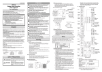
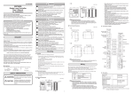
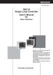
■ Dimensions
● C15T (Panel mounting type)
(Unit: mm)
2
60
Mounting bracket (Accessory)
48
Terminal screw M3
SDC15
48
sp
59
44.8
pv
mode
rdy
man
ev1
ev2
ev3
ot1
ot2
para
Handling Precautions
Tighten the screws of the attached mounting bracket. When the mounting bracket is secured firmly so that no play
exists, tighten the screws further by half-turn to fix the bracket to the panel. If the screws are tightened excessively,
this may cause the case to deform.
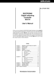
● C15S (Socket mounting type)
● Socket 81446391-001 (Optional unit)
74.2
31
61.2
48
51
26.5
Terminal screw M3.5
8
7
6
5
SDC15
4
pv
sp
71
48
2- M4 mounting hole
mode
rdy
man
ev1
ev2
ev3
ot1
40
ot2
para
9
Stopper
3
11
1
2
3.4
10
Socket
Put the stopper in the upper and lower holes in the main body of this
controller and secure the socket firmly.
● Panel cutout diagram
Individual mounting
+0.5
0
+0.5
0
45
+0.5
0
+0.5
0
(48xN -3)
45
45
50 min.
30 min.
Side-by-side mounting
("N" shows the number of mounted units.)
Handling Precautions
• When mounting three or more units tightly in the horizontal direction, pay
special attention so that the ambient temperature does not exceed 40°C.
• When the water-proof structure is required, always mount the unit individually after the gasket supplied with this controller has been mounted
on the main body.
• Keep a space of 50 mm or more in the vertical direction.
9
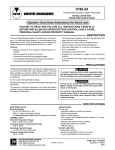
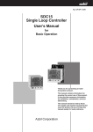
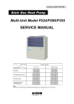
■ Part Names and Functions
(1)
sp
(4)
(2)
mode
rdy
man
ev1
ev2
ev3
ot1
ot2
(3)
para
(6)
<
(5)
(7)
<
(1) Display No. 1: Shows the PV value (current temperature,
etc.) or setting items.
(2) Display No. 2: Shows the SP value (set temperature, etc.)
or the set value of each setting item.
(3) Mode indicators
rdy :
Lights in READY mode (control stop).
man:
Lights in MANUAL mode (manual operation mode).
ev1 to ev3: Lights when event relay output is ON.
ot1 to ot2: Lights when control output is ON.
(4) [mode] key: When this key is kept pressed for 1s or
longer, the operation which has been set previously can be performed.
The default setting before shipment is the
RUN/READY selection.
(5) [para] key:
Changes the display.
(6) <, , key: Increases or decreases the numeric value, or
shifts the digit.
(7) Loader connector:
Connects a personal computer using the
dedicated cable supplied with the Smart
Loader Package.
pv
■ Terminal Connection Diagram
• Wiring of C15S
• Wiring of C15T
Control output
Relay
Voltage pulse
Voltage pulse
Current
Voltage pulse
Voltage pulse
Current
Current
Current
CT2
+
‐
1
2
3
+
1‐
2+
1
2
3
+
1‐
2+
1
2
+
‐
1
2
3
4
1
13
7
2
14
8
3
15
9
4
16
10
5
17
11
6
18
12
7
8
9
10
3
+
C
4
5
6
B
RTD
A
+
Current
Voltage
mA
V
4
‐
5
+ 6
+
-
4
+
3
6
7
8
9
7
8
+
mA
Voltage
V
11
+
C
100 to 240Vac
B
RTD
A
Thermocouple
+
3
2
1
1
2
Relay individual
contact
Power supply
10
8
7
6
3
2
1
3
2
1
Relay
2
11
PV input
Current
1
10
1
Relay individual
contact
3
9
2
1
2
6
5
4
12
4
5
6
‐
4
Current
PV input
Thermocouple
-
5
Relay
Power supply
+
1‐
2+
5
Voltage pulse
1
2
6
7
8
9
Relay
Event output
7
8
9
10
Event output
5
13
14
15
CT1
1
2
Control output
CT input
1
2
3
5
100 to 240Vac
11
4
9
3
10 11
1
2
Socket terminal No.
DI/COM
2
1
16
17
18
● Connection of RS-485 communication
RS-485 is a 3-wire connection.
Digital input
16
17
DA
DA
DB
SG
16
17
18
RS-485
communication
DB
18
SG
RS-485
Example: Connection with 5-wire instrument
Handling Precautions
Do not connect any external terminating resistor since a device similar to the terminating resistor is built-into this controller.
10
3. Installation environment noise sources and
preventive measures
● Precautions on the use of self-tuning function
The final control devices must be powered up simultaneously with or prior to the instrument when the selftuning function is to be used.
Generally, the following may be the noise sources in the
installation environment:
Relay and contact, electromagnetic coil, solenoid valve,
power supply line (particularly, 100Vac or more), motor
commutator, phase angle control SCR, radio communication device, welding machine, high-voltage ignitor, etc.
● Precautions on wiring
1. Isolation within instrument
Solid line portions "
Dotted line portions "
" are isolated.
" are not isolated.
Power supply
Control output 1
PV input
Control output 2
CT input 1
CT input 2
Internal
Loader communication
circuit
Preventive measures against fast rise noise
Use of CR filter is effective to prevent fast rise noise.
Recommended filter:
Yamatake's model No. 81446365-001
(Equivalent to 953M500333311 made by Matsuo
Electric.)
Event output 1
Event output 1 (Individual contact)
4. Wiring precautions
Event output 2
(1)
Event output 3 Event output 1
(Individual contact)
Digital input 1 RS-485
Digital input 2 communication
(2)
Available inputs and outputs may vary depending on the model.
2. Preventive measures against noise of instrument power supply
(1) Reduction of noise
Even though the noise is small, the noise filter is used
to eliminate the effect of the noise as much as possible.
Instrument power supply
100 to 240Vac
Noise filter
5. Inspection after wiring
After the wiring work has been completed, always inspect and check the wiring status. Great care should
be taken since incorrect wiring may cause the instrument to malfunction or severe personal injury.
C15T C15S
11
10
12
11
(2) When noise is excessive
If a large amount of noise exists, appropriate isolation
transformer and line filter are used to eliminate the
effect of the noise.
Instrument
power supply
100 to 240Vac
Insulation
transformer
(100/100V)
(200/200V)
Line filter
Yamatake's model No.
E81446364-001
(Equivalent to ZAC2205-00U
made by TDK)
1
3
E GND
2
4
Other circuit
C15T
C15S
11
10
12
11
After taking the noise preventive measures, do not bundle
the primary and secondary power cables together or put
both power cables in the same conduit or duct.
Keep the input/output and communication lines 50 cm
or more away from the power lines and power supply
lines having a voltage of 100Vac or more.
Additionally, do not put these lines together in the same
conduit or duct.
Grounding
11
RESTRICTIONS ON USE
This product has been designed, developed and manufactured for general-purpose application in machinery and equipment.
Accordingly, when used in the applications outlined below, special care should be taken to implement a fail-safe and/or redundant
design concept as well as a periodic maintenance program.
• Safety devices for plant worker protection • Start/stop control devices for transportation and material handling machines
• Aeronautical/aerospace machines
• Control devices for nuclear reactors
Never use this product in applications where human safety may be put at risk.
Specifications are subject to change without notice.
Advanced Automation Company
International Business Headquarters
Totate International Building
2-12-19 Shibuya Shibuya-ku
Tokyo 150-8316 Japan
URL:http://www.yamatake.com
This has been printed on recycled paper.
Printed in Japan. (H)
1st Edition: Issued in May, 2003
(01)
12