1
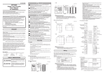
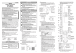
UNPACKING 2007 Yamatake Corporation ALL RIGHTS RESERVED MANUALS This manual explains the handling precautions, mounting, wiring, PV range type and main specifications only. See the separate manuals listed below for detailed handling procedures, setting methods, etc. These manuals also contain information on using various functions. Please read them as necessary. Displays and Settings (CP-SP-1265E) • SDC45/46 • SDC45A/46A Installation and Configuration (CP-SP-1218E) • SDC45V/46V Computational Functions (CP-SP-1275E) • SLP-C45 Smart Loader Package (CP-UM-5458E) Manuals can be downloaded from http://www.yamatake.com. WARNING Warnings are indicated when mishandling this product might result in death or serious injury to the user. CAUTION Cautions are indicated when mishandling this product might result in minor injury to the user, or only physical damage to this product. ■ Mounting procedure · Mount horizontally with the back not tilted more than 10 º up or down. · The mounting panel should be rigid and no more then 7 mm thick (5 mm max. when a gasket is used). WARNING Before connecting the SDC45/46 to the measurement target or to external control circuits, make sure that the frame ground (FG) terminal is properly grounded with an earth of less than 100 Ω. Failure to so might cause an electric shock or fire. Incorrect wiring of the SDC45/46 can damage the SDC45/46 and lead to other hazards. Check that the SDC45/46 has been correctly wired before turning the power ON. Before wiring, removing or mounting the SDC45/46, be sure to turn the power OFF. Failure to do so might cause electric shock or device failure. Do not touch electrically charged parts such as the power terminals. Doing so might cause electric shock. Do not disassemble the SDC45/46. Doing so might cause electric shock or device failure. Handling Precautions • When used as a waterproof unit, be sure to install a gasket. ■ External dimensions • SDC45 11 48 Unit: mm 43.8 130 2 91.4 (96xN–4) +0.5 0 CAUTION Gasket (accessory) Use the SDC45/46 within the operating ranges recommended in the specifications (temperature, humidity, voltage, vibration, shock, mounting direction, atmosphere, etc.). Failure to do so might cause fire or device failure. Wire the SDC45/46 properly using the specified types of wire and following recognized installation methods. Failure to do so might cause electric shock, fire or device failure. Do not allow wire clippings, chips or water to enter the controller case. They might cause fire or device failure. Firmly tighten the terminal screws to the torque listed in the specifications. Insufficient tightening of terminal screws might cause electric shock or fire. Do not use unused terminals on the SDC45/46 as relay terminals. Doing so might cause electric shock, fire or device failure. We recommend attaching the terminal cover (sold separately) after wiring the SDC45/46. Failure to do so might cause electric shock. Use the relays within the recommended service life. Failure to do so might cause fire or device failure. Use Yamatake Corporation's SURGENON if there is a risk of power surges caused by lightning. Otherwise fire or device failure could result. Do not block ventilation holes. Doing so might cause fire or device failure. Do not operate the keys with a mechenical pencil or other sharp-tipped object. Doing so might cause device failure. After the power has been turned ON, the SDC45/46 does not operate for 2 to 60 s according to the settings. There-fore, great care should be taken if the relay output from the controller is used as an interlock signal. Dispose of the battery appropriately, following local regulations. Mounting bracket (accessory) M3 terminal screw • SDC46 Unit: mm 11 96 91.4 130 91.4 2 Gasket (accessory) Mounting bracket (accessory) M3 Terminal screw Handling Precautions • To fasten this controller onto the panel, tighten the mounting bracket screws until there is no play between the bracket and panel, and then turn one more full turn. Excessively tightening the screws may deform the controller case. ■ Panel cutout dimensions • SDC45 50 min. 1 Unit: mm Gang-mounting (SDC45A/V only) Stand-alone mounting 44+0.5 0 (48xN–4) +0.5 0 92 +0.5 0 92 +0.5 0 50 min. Handling Precautions • For waterproof or dustproof use, be sure to mount with the stand-alone mounting method. • Mount the SDC45R/46R with the stand-alone mounting method only. • When three or more units are gang-mounted horizontally, the maximum allowable ambient temperature is 40 °C. • Provide a space of at least 50 mm or more above and below the controller. WIRING Be sure to provide a switch within operator reach for shutting off the main power supply to the controller in the main supply wiring. Also, in case of AC power supply models, the main supply wiring also requires a time-lagged (T) fuse rated at 1.0A, 250 V. (IEC127) Symbols used on the wiring label on the controller side: Symbol Meaning AC power supply DC power supply Caution, danger of electric shock Caution Handling Precautions 110 Be sure that the user receives this manual before the product is used. Copying or duplicating this user’s manual in part or in whole is forbidden. The information and specifications in this manual are subject to change without notice. Considerable effort has been made to ensure that this manual is free from inaccuracies and omissions. If you should find an error or omission, please contact Yamatake Corporation. In no event is Yamatake Corporation liable to anyone for any indirect, special or consequential damages as a result of using this product. SAFETY PRECAUTIONS 110 NOTICE Install the controller in a location that meets the following criteria: · Voltage to ground of 33 V r.m.s max., 46.7 V peak max., and 70 Vdc max. · No high/low temperature/humidity. · Free from sulfide gas or corrosive gas. · Not dusty or sooty. · Protected from direct sunlight, wind, and rain. · Little mechanical vibration or shock. · Not close to high voltage line, welding machine or other electrical noise generating source. · At least 15 meters away from the high voltage ignition device for a boiler. · No strong magnetic fields. · No flammable liquid or gas. 92 +0.5 0 This product has been designed, developed and manufactured for general-purpose application in machinery and equipment. Accordingly, when used in applications outlined below, special care should be taken to implement a fail-safe and/or redundant design concept as well as a periodic maintenance program. • Safety devices for plant worker protection • Start/stop control devices for transportation and material handling machines • Aeronautical/aerospace machines • Control devices for nuclear reactors Never use this product in applications where human safety may be put at risk. 92 +0.5 0 ■ Location 92 +0.5 0 RESTRICTIONS ON USE 50 min. Check the following items when removing the SDC45/46 from its package: Part No. Qty. Remarks Item Mounting bracket 81405411-004 2 Gasket (for SDC45) 81421863-001 1 (for SDC46) 81421864-001 1 User's manual CP-UM-5445E 1 This manual User's manual CP-UM-5445 1 Japanese Displays and Settings CP-UM-5457 1 Japanese If there is any problem with your order, please contact your sales representative immediately. 50 min. Thank you for purchasing the SDC45/46 Digital Indicating Controller. To ensure correct and safe operation of the SDC45/46, be sure to read and understand this user's manual. Be sure to keep this manual nearby for handy reference. Unit: mm Gang-mounting (SDC46A/V only) Stand-alone mounting 96 SDC45/46 Digital Indicating Controller User's Manual for Installation • SDC46 MOUNTING 96 CP-UM-5445E • Before wiring the SDC45/46, verify the controller's model No. and terminal Nos. written on the label on the side. Inspect all wiring once wiring work has been completed. • Use M3 crimp-type terminal lugs for wiring to terminals. • Leave a distance of at least 50 cm between I/O lead wires or communications lead wires and power lead wires. Also, do not pass these lead wires through the same conduit or wiring duct. • Be careful not to allow any crimp-type terminal lugs to touch adjacent terminals. • Be sure that any device or equipment which is connected to this controller has adequate insulation for the controller's power supply voltage and maximum I/O voltages. • The controller requires 2 to 60 seconds according to the settings to start up once the power is turned ON. A warm-up time of at least 30 minutes is recommended to allow the controller to attain the specified accuracy. • Prepare a heater current conductor to send a heater current through the current transformer. Do not use a heater current that exceeds the specified permissible current as this may damage the controller. • The current transformer input cannot be used for phase control. • Do not wire in the same duct for the motor drive terminals and the MFB input terminals and also do not use 6-core cable. Failure to follow the instruction might cause controller malfunction due to noise during motor startup operation. ● Wiring ● SDC45 rear panel A NAMES AND FUNCTION OF PARTS ● SDC46 rear panel C F A C D ● SDC46 front panel ● SDC45 front panel E F (7) (5) (1) (6) (5) (3) (5) (7) (1) (3) (2) (6) (2) Description Description (2) (1) (1) 1 (3) + - (1) C1 (3) (2) + - Output 3 (OUT3) (1) Relay (2) Triac (3) Current, voltage pulse, continuous voltage Output 4 (OUT4) (1) Relay (2) Triac (3) Current, voltage pulse Digital input/output (DI/DO) (1) DI (2) DO COM(-) (2) + - C2 C3 C3 C3 C4 C4 C4 C5 C5 Output 6 (OUT6) Current - C6 C6 D1 + C8 C8 - RS-485 COM(-) RS-485 DA DB DB SG SG F(SDC45R/46R) F (SDC45A/46A/45V/46V) Description Description Digital output (DO) (3) (2) (1) F1 1 T E2 2 F2 voltage input (AC) 2 AC (16) (15) (14) (14) (8) (1) Upper display: Displays PV (present temperature etc.) or setup items. (2) Lower display: Displays SP (set temperature, etc.) and other parameters. (3) Auxiliary display: Displays group No., loop* No., and channel No. of setup item. (4) Multi-status indicator: Indicates MV or DI/DO status. (5) Mode indicators: rdy: rsp: man: out1-7: Lights up in READY mode. Lights up in RSP (remote setting input) mode. Lights up in MANUAL mode. Light up when the output is ON (SDC45: out1-5). (8) [ Unused Unused D4 E4 D5 E5 (1) (2) (4) (3) A + 2 (PV22) V + E6 D6 - - V/mA - B + V/mA 1 (PV21) - mV D7 E7 D8 E8 Unused + + C (1) (2) A (3) + Unused - B V/mA - PV input 2 (PV2) (1) Thermocouple (2) Resistance temperature detector (3-wire system) (3) DC voltage/ current (4) DC voltage/ current + DC voltage * PV input 1(PV1) (1) Thermocouple (2) Resistance temperature detector (3-wire system) (3) DC voltage/ current (1) (2) A (3) A D + V - (1) B B C C A (2) PV input 1(PV1) A D B B C C PV input 2 (PV2) (1) Resistance temperature detector (3-wire system) (2) Resistance temperature detector (4-wire system) (3) DC voltage (1) Resistance temperature detector (3-wire system) (2) Resistance temperature detector (4-wire system) mV + C + * 3-input SDC45V/46V model only. ● I/O isolation Items surrounded by solid lines are isolated from other signals. Availability of inputs and outputs varies depending on the model number. PV1 OUT1 PV2/PV21/PV22 OUT2 OUT3 OUT4 DI-C1 to DI-C8 CT1/CT2/AC1/AC2 (17) ], [ ],[ ], [ ] keys: Used to increment/decrement numeric values and shift between digits or settable items. E3 D3 MFB (17) (13) (10) (12) (7) Loop number indicators: pv1, pv2: Light up to indicate which loop has the displayed PV value. 1 AC G CT DI-F1 to DI-F2 (13) (12) (9) (6) User function indicators: uf1-4: Light under user-assigned conditions (SDC45: uf1, uf2). Heater power supply Other input (1) Digital input (DI) (2) Current transformer input (CT) (3) Motor feedback input (MFB) Y CT DI-D1 to DI-D8 (10) (5) (4) (11) *The series of connections from PV input to PID operation through to control output is generically called a loop. 4 E1 D2 Output 7 (OUT7) Current Transmitter power supply C7 C7 Output 4 (OUT4) (1) Motor Description Digital input (DI) (4) (11) 3 E (SDC46) Description (8) (9) (16)(15) + Output 5 (OUT5) (1) Relay (2) Current, vontinuous voltage, transmitter power supply D (SDC46) C1 C1 DA (1) Digital input (DI) C2 Output 3 (OUT3) (1) Motor (1) Description C2 A (SDC46 Motor drive relay model) 2 (2) (2) Output 1, Output 2 (OUT1/OUT2) (1) Relay (1a1b) (2) Relay (1a) (2) 2 (1) (1) Power supply (1) AC power supply 100 to 240 Vac (2) DC power supply 24 Vdc (non polar) 1 C (SDC46) C (SDC45) A (both SDC45 and 46) Internal circuit OUT5 OUT6 OUT7 DO-C1 to DO-C8 DO-E1 to DO-E8 RS-485 Loader The power circuit is isolated from all inputs/outputs, communications and internal circuits. Handling Precautions • The loader jack is not isolated from the internal circuits. Always put the cap on the loader jack when the loader is not used. • On a motor driving relay model, OUT3 and OUT4 are not isolated. 2 (9) [auto/man] key: Used to change AUTO/MANUAL mode. (10) [sp/ev] key: Used to set the SP/EV bank. (11) [display] key: Used to change the display contents in the operation display mode. (12) [para] key: Used to set the PARA bank. (13) [enter] key: Used in initiating setup and to confirm changed values. (14) [f1], [f2] keys: Used for user-assigned functions (SDC46 only). (15) [at] key: Used to execute/cancel auto-tuning, or for user-assigned functions. (16) [rsp/lsp] key: Used to change between remote and local set point, or for user-assigned functions. (17) Loader jack: Jack for connection of PC loader cable (with cap). PV RANGE TABLE MODEL SELECTION TABLE Input indication accuracy differs depending on the sensor type. If PV-01 is set to a value that is not in the tables below, the input indication will be fixed at 0.0. ■ SDC45A/V (with 14-digit model No.) ■ Thermocouple ■ Resistance temperature detector On the 3-input model, RTD input cannot be used for PV21/22. For the linear input of the SDC45R/46R, an RTD cannot be used. For the SDC45A/46A/45V/46V, 21, 22, 31 and 32 can be used. For the SDC45R/46R, 23, 24, 33 and 34 can be used. PV-01 Sensor Input indication Wiring method Range setting type accuracy 21 Pt100 3-wire system -200.0 to +850.0°C -328.0 to +1562.0 °F ±0.3°C 22 3-wire system -200.00 to +300.00°C -328.0 to +572.0 °F ±0.15°C 23 3-wire system 0.00 to 100.00°C 32.00 to 212.00 °F ±0.050°C 24 4-wire system 0.000to 32.000°C 31 JPt100 3-wire system -200.0 to +640.0°C -328.0 to +1184.0 °F ±0.3°C 32 3-wire system -200.00 to +300.00°C -328.0 to +572.0 °F ±0.15°C 33 3-wire system 0.00 to 100.00°C 32.00 to 212.00 °F ±0.050°C 34 4-wire system 0.000to 32.000°C ALARM CODE LIST 4 0 Voltage 0 -10 0 -100 0 -1 1 0 0 Range 2 inputs (2 full multiple) 3 3 inputs (1 full multiple, 2 linear) *2 A 100 to 240 Vac D 24 Vdc 1 form 1a1b relay 2 2 form 1a relays C0 Current output (OUT 3) D0 Continuous voltage output (OUT 3) V0 Voltage pulse output (OUT 3) RR 2 form 1a relays CC 2 current outputs VV 2 voltage pulse outputs CV Current (OUT 3) + voltage pulse (OUT 4) SS Motor drive triac + MFB input 0 None R Form 1a relay C Current output D Continuous voltage output P Transmitter power supply AL04 AL05 AL06 AL2 1 AL22 AL25 AL26 AL7 1 AL72 AL8 1 AL82 AL83 AL96 AL97 AL98 AL99 PV1 input failure (under-range) PV2/PV21 input failure (over-range) PV2/PV21 input failure (under-range) PV22 input failure (over-range) Sensor burnout, incorrect wiring, incorrect PV2/PV21 range type setting. 2 inputs (2 full multiple) 2 3 inputs (1 full multiple, 2 linear) *2 3 100 to 240 Vac A 24 Vdc 1 form 1a1b relay 1 2 form 1a relays 2 C0 Current output (OUT 3) D0 Continuous voltage output (OUT 3) V0 Voltage pulse output (OUT 3) RR 2 form 1a relays CC 2 current outputs VV 2 voltage pulse outputs CV Current (OUT 3) + voltage pulse (OUT 4) 2 digital inputs (DI-F1/2) *3 1 10 digital inputs *4 2 2 digital inputs + 8 digital outputs *3 3 2 digital inputs + 8 digital outputs + RS-485 communication *3 4 2 CT inputs *5 *2: SDC45V only. *3: There are no digital inputs if “SS” is selected for Output 3, 4. 5 2 CT inputs + 8 digital inputs *5 6 2 CT inputs + 8 digital outputs *5 7 0 *5: Cannot be selected if “SS” is selected for Output 3, 4. Input indication accuracy Motor drive triac + MFB input SS Motor drive relay + MFB input 0 None *4 R Form 1a relay *4 C Current output *4 D Continuous voltage output *4 Transmitter power supply *4 P 0 *1: Not available for SDC46V. 0 None 1 Current output (OUT 6) 2 Transmitter power supply (OUT 7) 3 2 current outputs *3 4 *2: SDC46V only. *3: Not available if “CC” is selected for Output 3, 4 and “C” is selected for Output 5. 2 CT inputs + 8 digital outputs + RS-485 communication *5 *4: Selection must be “0” if “R1” is selected for Output 3, 4. None *5: There are no digital inputs if “SS” or “R1” is selected for Output 3, 4. Current (OUT 6) + transmitter power supply (OUT 7) 0 2 digital inputs (DI-F1/2) *5 1 14 digital inputs *6 2 14 digital inputs + 8 digital outputs *6 3 14 digital inputs + 8 digital outputs + RS-485 communication *6 4 2 CT inputs *7 5 2 CT inputs + 12 digital inputs *7 6 2 CT inputs + 12 digital inputs + 8 digital outputs *7 T Tropicalization treatment K Anti-sulfide treatment D Inspection certificate B Tropicalization treatment + inspection certificate L Anti-sulfide treatment + inspection certificate 0 None Y Complying with the traceability certification T Tropicalization treatment Z Tropicalization treatment + Complying with the traceability certification K Anti-sulfide treatment D Inspection certificate Anti-sulfide treatment + Complying with the traceability certification B Tropicalization treatment + inspection certificate 0 None L Anti-sulfide treatment + inspection certificate 1 LEDs: all orange Y Complying with the traceability certification Z Tropicalization treatment + Complying with the traceability certification X *6: There are 12 digital inputs if “SS” or “R1” is selected for Output 3, 4. *7: Not available if “SS” or “R1” is selected for Output 3, 4. 7 2 CT inputs + 12 digital inputs + 8 digital outputs + RS-485 communication *7 X ■ SDC45R C45R LEDs: all orange C46R 2 inputs (1 RTD, 1 linear) 1 2 2 inputs (2 RTDs) 2 2 inputs (1 RTD, 1 linear) 2 inputs (2 RTDs) 100 to 240 Vac A 24 Vdc D 100 to 240 Vac 24 Vdc 1 1 form 1a1b relay 1 2 2 form 1a relays 2 1 form 1a1b relay 2 form 1a relays CC 2 current outputs CC VV 2 voltage pulse outputs VV Form 1a relay R 2 current outputs 2 voltage pulse outputs Form 1a relay R None 0 0 2 AC inputs 3 1 2 AC inputs + 8 digital inputs 0 2 AC inputs 8 2 AC inputs + RS-485 communication 1 2 AC inputs + 12 digital inputs D Inspection certificate 8 Y Complying with the traceability certification D None Y 0 0 None 2 current outputs 2 AC inputs + RS-485 communication Inspection certificate Complying with the traceability certification 0 ■ SDC45A (with 7-digit model No.) Displays have all-orange LEDs. Basic Set No. Option Option model No. 2 1 C45A Specifications None Basic Set No. Option Option model No. 2 1 C46A Specifications Standard model : 2 alarm outputs (OUT 1/2) + 1 current output (OUT 6) None 0 Regular type 1: 2 relay outputs (OUT 3/4) +1 current output (OUT 5) + 0 0 Regular type 1: 2 relay output (OUT 3/4) + 1 current output (OUT 5) + 1 Regular type 2: 1 current output (OUT 3) + 1 voltage pulse output (OUT 4) + 2 digital inputs (DI-F1/2) 2 digital inputs (DI-F1/2) 1 Regular type 2: 1 current output (OUT 3) + 1 voltage pulse output (OUT 4) + 2 Position proportion type 1: 2 triac outputs (OUT 3/4) + 1 relay output (OUT 5) 2 Position proportion type 1: 2 triac outputs (OUT 3/4) + 1 relay output (OUT 5) 3 Regular type 3: 2 current outputs (OUT 3/4) + transmitter power supply 3 Regular type 3: 2 current outputs (OUT 3/4) + transmitter power supply 4 Position proportion type 2: 2 triac outputs (OUT 3/4) +1 relay output (OUT 5) 1 relay output (OUT 5) + 2 digital inputs (DI-F1/2) 1 relay output (OUT 5) + 2 digital inputs (DI-F1/2) (24 Vdc) (OUT 5) + 2 digital inputs (DI-F1/2) Position proportion type 2: 2 triac outputs (output3/4) + transmitter power supply 4 (24 Vdc) (OUT 7) + 2 digital inputs (DI-F1/2) (24 Vdc) (OUT 5) 3 None ■ SDC46A (with 7-digit model No.) Displays have all-orange LEDs. Standard model : 2 alarm outputs (OUT 1/2) 0 Specifications High accuracy model (mask size: 96W X 96H mm) 1 A Sensor burnout, incorrect wiring, Check the wiring, reset PV22 range type (PV-0 1) or reset PV22 incorrect PV22 range type setting. range upper/lower value. PV22 input failure (under-range) (PV-04: range lower value, PV-05: range upper value.) MFB input failure Burnout, incorrect wiring. Check the wiring. Motor adjustment failure Burnout, incorrect wiring, Readjust the motor after checking the wiring and motor power. Motor power shutdown. CT1 input failure CT input over-range Check CT input. CT2 input failure Incorrect CT range type setting. Reset CT input. Abnormal PV1 CJ compensation Abnormal terminal temperature. Check the ambient temperature. Abnormal PV2 CJ compensation (thermocouple) Battery low (SDC45V/46V only) Dead battery Replace the battery. Internal clock failure (SDC45V/46V only) Dead battery, Hardware failure. Reset the clock after battery is replaced.. Replace the unit. Board configuration problem Hardware failure. Replace the unit. Main board failure Parameter failure •Power was turned OFF while Restart the system. Reset data or replace the unit. setting data. (AL97: setting data, AL98: adjustment data) •Data is corrupted due to noise, etc. Adjustment data problem ROM failure ROM (memory) is faulty. Restart the system. Replace the unit. None 1 Basic Input Power Output Output Output Output Option Addition Addition 2 1 5 6, 7 model No. model supply 1, 2 3, 4 Specifications High accuracy model (mask size: 48W X 96H mm) Corrective action Check the wiring, reset PV1 range type (PV-0 1) or reset PV1 range upper/lower value. (PV-04: range lower value, PV-05: range upper value.) Check the wiring, reset PV2/PV21 range type (PV-02) or reset PV2/PV21 range upper/lower value. (PV-04: range lower value, PV-05: range upper value.) Anti-sulfide treatment + Complying with the traceability certification 0 ■ SDC46R Basic Input Power Output Output Output Output Option Addition Addition 2 1 5 6, 7 model No. model supply 1, 2 3, 4 D AL02 AL03 1 input (1 full multiple) *1 1 R1 *1: Not available for SDC45V. Alarm codes and countermeasures in case of abnormal operation of this controller. Cause Sensor burnout, incorrect wiring, incorrect PV1 range type setting. Computation function model C46V None selected for Output 3, 4. to 20 mA ±0.1 % FS ± 1 digit to 20 mA to 10 mV to +10 mV to 100 mV to +100 mV to 1V to +1 V to 5V to 5V to 10 V Standard model C46A D 1 *4: There are 8 digital inputs if “SS” is On the 3-input model, PV21 can be set to 41, 42, 49, 51, or 51; and PV22 can be set to 49, 50 or 51. For the linear input of the SDC45R/46R, 47, 49 and 50 can be used. For the RTD input of the SDC45R/46R, DC voltage or DC current cannot be used. Input type Current 1 input (1 full multiple) *1 2 0 ■ DC voltage, DC current PV-01 setting 41 42 43 44 45 46 47 48 49 50 51 1 Specifications Input Power Output Output Output Output Option Addition Addition Basic 2 6, 7 5 3, 4 1 model No. model supply 1, 2 Computation function model C45V PV-01 Sensor Range Input indication accuracy setting type 1 K -270.0 to +1372.0 °C -454 to+2502 °F Under -200 °C: ±20.0 °C, Under -100 °C: ±1.0 °C, Under 400 °C: ±0.5 °C, 400 °C and above: ±0.1 % rdg. ±1 digit 2 E -270.0 to +1000.0 °C -454 to+1832 °F Under -200 °C: ±15.0 °C, Under -100 °C: ±1.0 °C, Under 400 °C: ±0.5 °C, 400 °C and above: ±0.1 % rdg. ±1 digit 3 J -200.0 to +1200.0 °C -328 to+2192 °F Under -100 °C: ±1.0 °C, Under 400 °C: +0.5 °C, 400 °C and above: +0.1 % rdg. ±1 digit 4 T -270.0 to +400.0 °C -454 to +752 °F Under -200 °C: ±10.0 °C, Under -100 °C: ±1.0 °C, -100 °C and above: ±0.5 °C 5 B 0.0 to 1800.0 °C 32 to 3272 °F Under 260 °C: ±70 °C, Under 800 °C: ±4 °C, 800 °C and above: ±2 °C 6 R -50.0 to +1768.0 °C -58 to+3214 °F Under 0 °C: ±4.0 °C, Under 1000 °C: ±2.0 °C, 1000 °C and above: ±0.1 % rdg. ±1 digit 7 S -50.0 to +1768.0 °C -58 to+3214 °F 8 WRe5-26 0.0 to 2300.0 °C 32 to 4172 °F Under 1400 °C: ±1.5 °C, 1400 °C and above: ±0.1 % rdg. ±1 digit 9 PR40-20 0.0 to 1900.0 °C 32 to 3452 °F Under 300 °C: ±40 °C, Under 800 °C: ±20 °C, 800 °C and above: ±8 °C 10 Ni-Ni•Mo 0.0 to 1300.0 °C 32 to 2372 °F ±1.4 °C 11 N -200.0 to +1300.0 °C -328 to+2372 °F Under 0 °C: ±4.0 °C, 0 °C and above: ±1.4 °C 12 PL II 0.0 to 1390.0 °C 32 to 2534 °F ±1.4 °C 13 DIN U -200.0 to 600.0 °C -328 to+1112 °F Under 0 °C: ±1.0 °C, 0 °C and above: ±0.7 °C 14 DIN L -200.0 to +900.0 °C -328 to+1652 °F Under 0 °C: ±1.5 °C, 0 °C and above: ±1.0 °C 15 Gold-iron/ -273.0 to +27.0 °C -459 to +80 °F ±1.5 °C Chromel Specifications Standard model C45A On the 3-input model, thermocouple input cannot be used for PV21/22. For the SDC45R/46R, thermocouple cannot be used. Alarm code Failure name AL0 1 PV1 input failure (over-range) ■ SDC46A/V (with 14-digit model No.) Input Power Output Output Output Output Option Addition Addition Basic 2 1 6, 7 5 3, 4 model No. model supply 1, 2 transmitter power supply(24 Vdc) (OUT 7) 0 None 0 1 Communications (RS-485) + PV inputs 2 + 8 digital outputs 1 Communications (RS-485) + PV input 2 + 12 digital inputs + 8 digital outputs 2 PV input 2 + 8 digital outputs 2 PV input 2 + 12 digital inputs + 8 digital outputs 3 8 digital outputs 3 12 digital inputs +8 digital outputs 4 PV input 2 4 PV input 2 None MAINTENANCE Cleaning: Part replacement: Fuse replacement: When removing dirt from the instrument, wipe it off with a soft cloth rag. Do not replace any parts of this unit. When replacing the fuse connected to the electric wiring, always use the specified standard fuse. Standard IEC 127 Shut-down speed Slow-action type (T) Rated voltage 250 V Rated current 1.0 A EU DIPOSAL (SDC45V/46V only) ● Continuous voltage output Output current: 0 to 5 Vdc (0.0 to 5.5 Vdc) 1 to 5 Vdc (0.6 to 5.4 Vdc) 0 to 10 Vdc (0.0 to 11.0 Vdc) Load resistance: 1 kΩ min. Load limit current: 21 mA max. (standard value under standard conditions) Output accuracy: ± 0.1 % FS max. (standard conditions) Output resolution: 1/20000 (for 0 to 10 V) Input impedance: 110 Ω or less for current input Cold junction compensation accuracy: ± 0.5 °C (standard conditions) ± 1.0 °C (in the 0 to 50 °C ambient temperature range) Cold junction compensation method: Internal/external (0 °C only) compensation selectable ■ Motor feedback input (MFB) ● Voltage pulse output Output current: 12 Vdc +15 %/-10 % Load current: 30 mA max. Load limit current: 52 mA (standard value under standard conditions) OFF-state leakage current: 0.1 mA max. Allowable potentiometer value: 100 to 2,500 Ω Indication accuracy: ± 0.2 %FS (standard conditions) Sampling cycle: 100 ms ■ Current transformer input CAUTION When discarding this device, shut off the power and wait 10 minutes or longer before removing the battery. Failure to do so might cause an electric shock or burn. When the battery is removed, some settings and internal operation status data will be lost. Please dispose of used batteries properly, in accordance with local bylaws and regulations. When discarding this device, remove the battery following the procedure given below, and then dispose of it appropriately, following local regulations. ■ Battery removal procedure (1) Remove the case. Insert the flat head of a screwdriver into the grooves (on the top, bottom, right and left sides) between the front panel and the case, and then gradually pull the case off while gently prying with the screwdriver. (2) Remove the battery from the battery holder. Pull the battery upward. Battery Grooves Handling Precautions • The SDC45V/46V has a built-in battery that is used for memory backup. To remove/replace the battery, except when discarding this device, contact Yamatake Corporation. SPECIFICATIONS ■ PV input Thermocouple: K, E, J, T, B, R, S, N (JIS C 1602-1995) WRe5-26 (ASTM E988-96 (reapproved 2002)), PR40-20 (ASTM E1751-00), Ni-Ni•Mo (ASTM E1751-00), PL II (ASTM E1751-00), DIN U, DIN L (DIN 43710-1985) Gold-iron/chromel (ASTM E1751-00) Resistance temperature detector (RTD): Pt100 (JIS C 1604-1997) JPt100 (JIS C 1604-1989) DC voltage (mV range): 0 to 10 mV, -10 to +10 mV, 0 to 100 mV, -100 to +100 mV DC voltage (V range): 0 to 1 V, -1 to +1 V, 1 to 5 V, 0 to 5 V, 0 to 10 V DC current: 4 to 20 mA, 0 to 20 mA Sampling cycle: 25, 50, 100, 300 ms (determined by the sampling cycle setting) (SDC45A/46A) 100 ms (SDC45V/46V/45R/46R) Indication accuracy (under standard conditions) Thermocouple: ±0.1 % rdg. ±1 digit (determined by the range and measured temperature) Resistance temperature detector(RTD): ± 0.05 to 0.3 °C (determined by the range) DC voltage • DC current: ± 0.1 %FS ± 1 digit Compatible current transformer: QN212A (φ12, 800 T) QN206A (φ6, 800 T) Input range: 0 to 50 Aac Current measurement range: 0.0 to 55.0 Aac (Accuracy may be out of specifications for less than 0.4 Aac.) Indication accuracy: ± 3 %FS ± 1 digit Indication resolution: 0.1 Aac Input impedance: 10 Ω (typ) ● Motor drive output (triac output) Contact configuration: 1a Compatible motors: ECM3000F1**0 (100 Vac, relay contact input) ● Motor drive output (relay output) Contact configuration: 1a + 1a Contact rating: 2A 250 Vac max./(cosφ=0.4) 2.5 A 24 Vdc (L/R=0.7 ms) Contact voltage: 250 Vac max./125 Vdc max. Life: Min. 100,000 operations (under rated conditions) Min. switching specifications: 40 mA/24 Vdc ■ Heater power supply voltage input Input frequency: 50 Hz/60 Hz Input range: 0 to 12 Vac Voltage measurement range: 0 to 13.2 Vac (Accuracy may be out of specifications for less than 0.5 Vac.) Indication accuracy: ± 0.5 %FS ± 1 digit Indication resolution: 0.01 Vac Input impedance: 126 kΩ (typ) Transformer for detecting heater power supply voltage: 81406725-003 ● Transmitter power supply function Output current: 24 Vdc ± 10 % Load current: 30 mA max. Load limit current: 45 mA (standard value under standard conditions) ● Digital output (DO) Output type: Transistor (sink type) Load voltage: 4.5 to 28 Vdc Load current: 70 mA max./point 500 mA max./unit ON-state residual voltage: 0.5 V max. OFF-state leakage current: 0.1 mA max. ■ External switch input ● Digital input (DI) Connectable outputs: Dry contact or transistor (sink type) Open terminal voltage: 7 Vdc ± 15 %* Terminal current (during short-circuit): 3 to 7 mA* Allowable ON contact resistance: 500 Ω max.* Allowable OFF contact resistance: 100 kΩ min.* Allowable ON residual voltage: 1.5 V max.* Allowable OFF-state leakage current: 0.1 mA max.* *Under standard conditions. ■ RS-485 communications Transmission line: RS-485, 3 wire multi-drop Transmission speed: 4800, 9600, 19200, 38400 bps Communication distance: 500 m max. Connectable units: 32 max. (including master station) Communication system: Half-duplex, start/stop synchronization Terminating resistor: 150 Ω 1/2 W, at both ends of the line Bit length: 8 bits/7 bits Stop bit length: 1 or 2 bits Parity bit: Even parity, odd parity, or no parity Communication protocol: CPL, MODBUS conforming ■ Control output (Control output (OUT) • auxiliary output (AUX) • event output (EV)) ● Relay output (outputs 1 and 2) Contact configuration: 1a1b or 1a, selected by the model No. Contact rating: 3A 250 Vac/30 Vdc 1a1b, resistance load 1A 250 Vac/30 Vdc 1a, resistance load Contact voltage: 250 Vac max./125 Vdc max. Life: Min. 100,000 operations (under rated conditions) Min. switching specifications: 100 mA/5 Vdc 1a1b 10 mA/5 Vdc 1a ■ Environmental conditions ● Standard conditions Ambient temperature: 23 ± 2 °C (SDC45A/46A/45V/46V) 23 ± 0.1 °C (SDC45R/46R) Ambient humidity: 60 ± 5 %RH Rated power supply voltage: 105 Vac ± 1 % (100 to 240 Vac power model) 24 Vdc ± 5 % (100 to 240 Vac power model, SDC45A/46A/45V/46V) 24 Vdc ± 2 % (24 Vdc power model, SDC45R/46R) Power frequency: 50 ± 1 Hz or 60 ± 1 Hz (100 to 240 Vac power model) Vibration resistance: 0 m/s2 Shock resistance: 0 m/s2 Mounting angle: Reference plane ± 3 ° ● Relay output (outputs 3, 4 and 5) Contact configuration: 1a Contact rating: 3 A 250 Vac/30 Vdc (resistance load) Contact voltage: 250 Vac max./125 Vdc max. Life: Min. 100,000 operations (under rated conditions) Min. switching specifications: 100 mA/5 Vdc ● Current output Output current: 4 to 20 mAdc(2.4 to 21.6 mAdc) 0 to 20 mAdc(0.0 to 22.0 mAdc) Load resistance: 600 Ω max. Output accuracy: ± 0.1 % FS max. (standard conditions) Output resolution: 1/15000 Voltage (open): 23 Vdc max. ● Operating conditions Ambient temperature: 0 to 50 °C (SDC45A/46A/45V/46V) 20 to 25 °C (SDC45R/46R) Ambient humidity: 10 to 90 %RH (without condensation) 4 Rated power supply voltage: 85 to 264 Vac (100 to 240 Vac power model) 21.6 to 26.4 Vdc (24 Vdc power model) Power frequency: 50 ± 2 Hz or 60 ± 2 Hz (100 to 240 Vac power model) Vibration resistance: 0 to 2 m/s2 (10 to 60 Hz for 2 h each in X, Y, and Z directions) Shock resistance: 0 to 10 m/s2 Mounting angle: Reference plane ± 10 ° Altitude: 2000 m max. ● Transportation conditions Ambient temperature: -20 to +70 °C Ambient humidity: 10 to 95%RH (without condensation) Vibration resistance: 0 to 5 m/s2 (10 to 60 Hz for 2 h each in X, Y, and Z directions) Shock resistance: 0 to 500 m/s2 (3 times each in X, Y, and Z directions) ■ Memory backup Backup system: Serial EEPROM, battery and double layer capacitor for SRAM (SDC45V/SDC46V) Number of rewrite operations: Max. 100,000 for EEPROM; no limitation for SRAM Backup life: EEPROM 10 years SRAM • 3 years by battery (at 10 to 35 °C ambient temperature, without connection to power) • 30 min by double layer capacitor (while changing battery, at an ambient temperature of 35 °C or less, after capacitor is charged for 1 h or more) ■ Other specifications Power consumption: 30 VA max. (SDC45 100 to 240 Vac power model) 40 VA max. (SDC46 100 to 240 Vac power model) 12 W max. (SDC45 24 Vdc power model) 15 W max. (SDC46 24 Vdc power model) Power ON inrush current: 35 A max./10 ms max. (100 to 240 Vac power model) 20 A max./10 ms max. (24 Vdc power model) Allowable transient power loss: 20 ms min. Mass: Approx. 400g (SDC45, including dedicated mounting bracket) Approx. 700g (SDC46, including dedicated mounting bracket) Terminal screw tightening torque: 0.4 to 0.6 N•m Protection: IP65 (under operating conditions) Standards compliance: EN61010-1, EN61326 Overvoltage category: Category II (IEC60364-4-443, IEC60664-1) Allowable pollution degree: Pollution degree 2 OPTIONAL PARTS LIST Item Mounting bracket (2 units) Terminal cover* Current transformer Parts No. or model No. 81405411-003 81441420-001 QN212A (φ12) QN206A (φ6) Transformer for detecting 81406725-003 heater power supply voltage Hard cover 81441421-001 (for SDC45) 81441422-001 (for SDC46) * 1 cover for SDC45, 2 for SDC46. Specifications are subject to change without notice. (08) Advanced Automation Company 1-12-2 Kawana, Fujisawa Kanagawa 251-8522 Japan URL: http://www.azbil.com 1st Edition: Issued in Nov. 2007 (W) 5th Edition: Issued in Nov. 2008 (G) Flowchart of key operations and displays Operation display Heat/Cool control 1-loop AUTO mode is selected [display] key Loop 1 PV value Loop 1 PV value Loop 1 SP value [display] key Loop 1 PV value Heat/Cool control Loop 1 PV value [display] key Loop 1 MV value (Heat) Loop 1 MV value [display] key Loop 1 MV value (Cool) MANUAL mode is selected Heat/Cool control 2-loop AUTO mode is selected for both 2 loops Loop 1 PV value [display] key Loop 1 PV value [display] key Power ON (Loop 1) MANUAL mode is selected Setting display SP/EV bank [SP group selection bank] (Flashing) Keep [sp/ev] key for 2s SPNO Loop 1 PV value Heat/Cool control [display] key Loop 1 MV value (Heat) Heat/Cool control [display] key Loop 1 PV value [Loop 2 multi-SP bank] [Loop 1 recipe bank] [V] key or [sp/ev] key SPNO L. 1. [display] key Loop 2 PV value [display] key Loop 2 PV value Heat/Cool control [display] key Loop 2 MV value (Heat) Loop 2 MV value Loop 2 SP value Loop 2 PV value [display] key Loop 2 MV value (Cool) (Loop 2) [Loop 2 recipe bank] [RSP bank] PARA bank [Event setup bank] (Flashing) (Flashing) (Flashing) (Flashing) (Flashing) (Flashing) L 1.LSP L2.LSP L 1.REC L2.REC RSP EV Keep [para] key pressed for 2s [Loop 1 PID bank] [Mode bank] [V] key or [sp/ev] key (Flashing) MOdE [enter] key Keep [sp/ev] key for 2s SPNO(Lit) Loop 2 PV value Loop 1 MV value (Cool) Returns to the operation display immediately before the SP/EV bank is displayed. [display] key [Loop 1 multi-SP bank] [V] key or [sp/ev] key [display] key Loop 1 MV value Loop 1 SV value Loop 2 PV value Loop 1 PV value [V] key or [para] key Returns to the operation display immediately before the PARA bank is displayed. [display] key [Loop 2 PID bank] [SP configuration bank] [Event configuration bank] (Flashing) (Flashing) (Flashing) (Flashing) L 1.PI D L2.PI D SPCNF EVCNF L2.PI D(Lit) SPCNF(Lit) EVCNF(Lit) [Control bank] [MV bank] (Flashing) (Flashing) CTrL MV To be continued to the next page [enter] key L 1.LSP(Lit) L2.LSP(Lit) LSP.0 1 LSP.0 1 L. 1. L.2. PI D.0 1 PI D.0 1 SPNO L. 1. L.2. L.2. LSP.02 LSP.02 L. 1. L 1.REC(Lit) PI D.02 L. 1. L.2. LSP.03 LSP.03 L. 1. L.2. PI D.03 PI D.03 L. 1. L.2. LSP.04 LSP.04 L. 1. L.2. PI D.04 PI D.04 L. 1. L.2. LSP.05 LSP.05 L. 1. L.2. PI D.05 PI D.05 L. 1. L.2. LSP.06 LSP.06 L. 1. L.2. PI D.06 PI D.06 L. 1. L.2. LSP.07 LSP.07 L. 1. L.2. PI D.07 PI D.07 L. 1. L.2. LSP.08 LSP.08 L. 1. L.2. PI D.08 PI D.08 L. 1. L.2. LSP.09 LSP.09 L. 1. L.2. PI D.09 PI D.09 1.0 1. L. 1. L.2. LSP. 10 LSP. 10 L. 1. L.2. PI D. 10 PI D. 10 L. 1. L.2. LSP. 1 1 LSP. 1 1 L. 1. L.2. PI D. 1 1 PI D. 1 1 L. 1. L.2. LSP. 12 LSP. 12 L. 1. L.2. PI D. 12 PI D. 12 L. 1. L.2. LSP. 13 LSP. 13 L. 1. L.2. PI D. 13 PI D. 13 L. 1. L.2. LSP. 14 LSP. 14 L. 1. L.2. PI D. 14 PI D. 14 L. 1. L.2. LSP. 15 LSP. 15 L. 1. L.2. PI D. 15 PI D. 15 L. 1. L.2. LSP. 16 LSP. 16 L. 1. L.2. PI D. 16 PI D. 16 L. 1. L.2. 1. 16. 1.0 1. 1. 16. E02 E02 1.0 1. 1. 16. E02.SB E02.SB 1.0 1. 1. 16. E03 E03 1.0 1. 1. 16. E03.SB E03.SB 1.0 1. 1. 16. E04 E04 1.0 1. 1. 16. E04.SB E04.SB 1.0 1. 1. 16. E05 E05 1.0 1. 1. 16. E05.SB E05.SB 1.0 1. 1. 16. E06 E06 1.0 1. 1. 16. E06.SB E06.SB 1.0 1. 1. 16. E07 E07 1.0 1. 1. 16. E07.SB E07.SB 1.0 1. 1. 16. E08 E08 1.0 1. 1. 16. E08.SB E08.SB 1.0 1. P 1. 16. P 1.0 1. I 1. 16. I 1.0 1. D 1.0 1. OL RSP 2.0 1. E0 1 E0 1.SB E0 1.SB L.2. PI D.02 SP 1.0 1. E0 1 rSP(Lit) L2.REC(Lit) SP 1. 16. D 1. 16. OL E09 2.0 1. 2. 16. E 10 E 10 2.0 1. 2. 16. E 10.SB E 10.SB 2.0 1. 2. 16. E11 E11 2.0 1. 2. 16. E 1 1.SB E 1 1.SB 2.0 1. 2. 16. E 12 E 12 2.0 1. 2. 16. E 12.SB E 12.SB 2.0 1. 2. 16. E 13 E 13 2.0 1. 2. 16. E 13.SB E 13.SB 2.0 1. 2. 16. E 14 E 14 2.0 1. 2. 16. E 14.SB E 14.SB 2.0 1. 2. 16. E 15 E 15 2.0 1. 2. 16. E 15.SB E 15.SB 2.0 1. 2. 16. E 16 E 16 2.0 1. 2. 16. OI 1.0 1. 1. 16. OI 1. 16. OL-0 1 OL-0 1 CSP.02 RRA.02 EP-04 CNT.0 1 CNT.0 1 MV-04 CAS.03 L. 1. L. 1. L.2. L. 1. 0 1. L. 1. L. 1. CB OH-0 1 OH-0 1 CSP.03 RRA.03 EP-05 CNT.03 CNT.03 L. 1. L. 1. L.2. L. 1. RE-0 1 RE-0 1 CSP.04 RRA.04 L.2. L. 1. L.2. L. 1. E04 A---M P-0 1C P-0 1C CSP.05 RRA.05 L.2. L.2. L.2. L.2. 0 1. L. 1. EP-06 CNT.04 CNT.04 L.2. 0 1. L. 1. EP-07 CNT.05 CNT.05 L.2. L.2. L. 1. L.2. L. 1. E04.SB E 12.SB AT I -0 1C I -0 1C CSP.06 RRA.06 L.2. L. 1. L.2. L. 1. 0 1. L. 1. E05 L---R D-0 1C D-0 1C CSP.07 RRA.07 EP-09 CNT.07 CNT.07 0 1. E05.SB E 13.SB E06 E 14 L.2. OL.0 1C CSP.08 RRA.08 CNT.08 CNT.08 L.2. L. 1. L.2. L. 1. L. 1. OH.0 1C OH.0 1C CSP.09 CNT.09 CNT.09 L. 1. L.2. L. 1. L. 1. CSP. 1 1 L. 1. E07.SB E 15.SB CSP. 12 L.2. L.2. EP-0 1 16. EP-02 16. EP-03 P- 16 P- 16 L. 1. L. 1. L.2. RRA.0 1 16. I - 16 I - 16 L. 1. EP-04 L. 1. L.2. RRA.02 16. EP-05 D 2.0 1. 2. 16. Multi-SP is used (C-0 10=0) OL- 16 L. 1. L. 1. L.2. RRA.04 16. OH- 16 OH- 16 L. 1. EP-07 L. 1. L.2. RRA.05 16. RE- 16 RE- 16 L. 1. EP-08 L. 1. L.2. RRA.06 16. L. 1. EP-09 RRA.07 16. P- 16C P- 16C L. 1. L.2. I - 16C I - 16C L. 1. L.2. D- 16C D- 16C L. 1. L.2. OL. 16C OL. 16C L. 1. L.2. L. 1. RRA.08 L. 1. L.2. LMT.02 2.0 1. 2. 16. I -C I -C 2.0 1. 2. 16. L.2. D-C D-C CSP.02 2.0 1. 2. 16. L.2. OL.C OL.C CSP.03 2.0 1. 2. 16. L.2. OH.C OH.C CSP.04 2.0 1. 2. 16. L.2. OI OI CSP.05 2.0 1. 2. 16. L.2. OH. 16C L. 1. L.2. L.2. CSP.0 1 CSP.06 L.2. CSP.07 L.2. CSP.08 L.2. CSP.09 L.2. L.2. L.2. CNT. 10 CNT. 10 L. 1. L.2. ETD.0 1 ETD.0 1 L. 1. L.2. ETD.02 ETD.02 L. 1. L.2. ETD.03 ETD.03 L. 1. L.2. ETD.04 ETD.04 L. 1. L.2. ETD.05 ETD.05 L. 1. L.2. ETD.06 ETD.06 L. 1. L.2. ETD.07 ETD.07 L. 1. L.2. ETD.08 ETD.08 L. 1. L.2. ETD.09 ETD.09 L. 1. L.2. ETD. 1 1 ETD. 1 1 L.2. ETD. 12 ETD. 12 L. 1. P-C OH. 16C L. 1. L. 1. LMT.0 1 P-C Recipe is used (C-0 10=1) L.2. L. 1. CSP. 10 E08.SB E 16.SB L.2. OL.0 1C E 15 E 16 L. 1. CNT.06 CNT.06 CB L. 1. E08 L.2. 0 1. EP-08 L.2. E06.SB E 14.SB E07 L.2. L. 1. L.2. Multi-SP is used (C-0 10=0) L.2. D 2. 16. OH.C L---R R---R E 13 MV-03 CAS.02 L.2. 2. 16. RE L.2. iNp.03 iNp.03 L.2. ETD. 13 ETD. 13 L. 1. L.2. ETD. 14 ETD. 14 L. 1. L.2. ETD. 15 ETD. 15 L. 1. L.2. ETD. 16 ETD. 16 L. 1. L.2. ETD. 17 ETD. 17 L. 1. L.2. ETD. 18 ETD. 18 L. 1. L.2. L. 1. L. 1. L.2. L. 1. L. 1. L.2. L. 1. L.2. L. 1. L.2. MV-08 TR-0 1 L. 1. L.2. MV-09 TR-02 L. 1. L.2. MV- 10 TR-03 L. 1. MV- 1 1 L. 1. MV- 12 L. 1. MV- 13 L. 1. CAS.0 1 L. 1. CAS.02 L. 1. CAS.03 L. 1. CAS.04 L. 1. CAS.05 L. 1. CAS.06 L. 1. TR-0 1 L. 1. TR-02 L. 1. TR-03 L. 1. MV-0 1 L.2. MV-02 L.2. MV-03 L.2. MV-04 L.2. MV-05 L.2. MV-06 L.2. MV-07 MV-08 MV-09 L.2. * : Only SDC45V/46V L.2. MV-07 CAS.06 L.2. ETD.20 ETD.20 L.2. MV-06 CAS.05 L.2. ETD. 19 ETD. 19 L.2. MV-05 CAS.04 MV- 10 L.2. MV- 1 1 CSP. 10 L.2. L.2. MV- 12 L.2. 5 L.2. L. 1. I 2.0 1. 1.0 1. L. 1. L. 1. L. 1. CAS.0 1 * MV-02 L. 1. L.2. L. 1. 2.0 1. RE OH.C 0 1. L.2. I 1. 16. 1. 16. EP-03 MV-0 1 MV- 13 L. 1. OL- 16 RE OL.C CSP.0 1 RRA.0 1 2. 16. 1.0 1. 1.0 1. L.2. D-0 1 P RE OL.C L. 1. D-0 1 2.0 1. 2. 16. L.2. iNp.02 iNp.02 L. 1. 0 1. P OH L. 1. * AT E03.SB E 1 1.SB E 12 0 1. EP-02 16. 2.0 1. 1. 16. L.2. EP-06 OH D-C E11 L.2. MV(Lit) iNp.0 1 iNp.0 1 L. 1. RRA.03 1. 16. 1.0 1. E03 L. 1. LMT.02 CSP. 12 L.2. OH D-C E02.SB E 10.SB L.2. I -0 1 D- 16 1.0 1. 1. 16. RSP is used L. 1. I -0 1 L. 1. OH I -C E 10 L. 1. A---M CTRL(Lit) EP-0 1 D- 16 2. 16. 1.0 1. E02 LMT.0 1 CSP. 1 1 2. 16. OL I -C L. 1. P-0 1 2.0 1. 2.0 1. 1. 16. E0 1.SB E09.SB P-0 1 E 16.SB E 16.SB OL 1.0 1. PI D R---R L. 1. 1. 16. P-C [V] key or [para] key E09 2. 16. 1.0 1. P-C EV(Lit) E0 1 L. 1. E09 E09.SB E09.SB 2.0 1. Keep [para] key pressed for 2s MODE(Lit) L 1.PI D(Lit) L.2. Movement within bank Forward movement [sp/ev] key or [V] key (SP/EV bank) [para] key or [V] key (PARA bank) Backward movement [ ] key Return to the operation display immediately before the PARA bank is displayed V PARA bank [display] key [Setup bank] Continued from [V] key or the previous page (Flashing) [para] key SETUP [Priority bank] [PV bank] [Output bank] [CT input bank] [AC input bank] (Flashing) (Flashing) (Flashing) PrI OR PV OUT [Position proportional bank] [Linearization table bank] (only with CT input mdel) (only with AC input mdel) (only with motor drive mdel) (Flashing) (Flashing) (Flashing) (Flashing) cT ac [Internal contact [Digital output [Logical operation [User-defined bank] input bank] bank] bit bank] [Monitor bank] [Instrument information bank] (Flashing) (Flashing) (Flashing) (Flashing) (Flashing) (Flashing) (Flashing) (Flashing) (Flashing) (Flashing) (Flashing) (Flashing) IC DO BF UDB pv.CMp i n.Fnc Ot.Fnc HMI RS485 LOCK MONI id In.Fnc(Lit) Ot.fnc(Lit) TBL pp [Input compu- [Output compu[RS485 communi[Temperature and tation bank] [Display/Key cation bank] [Lock bank] pressure compensation tation bank] bank] (only SDC45V/46V) bank] (only SDC45V/46V) (only SDC45V/46V) (only SDC45V/46V) [enter] key Keep [para] key pressed for 2s SETUP(Lit) [V] key or [para] key C-00 1 C-040 PrI OR(Lit) PV(Lit) OUT(Lit) cT(Lit) ac(Lit) pp(Lit) TBL(Lit) I C(Lit) DO(Lit) BF(Lit) UDB(Lit) Pv.CMP(Lit) LPr.0 1 PV-0 1 CO-0 1 Ct-0 1 AC-0 1 pp-0 1 TB.DP TB.B. 14 TB.B.05 I C-0 1 DO.E.0 1 BF-0 1 UDB.AL pv.C.0 1 1. 1. 1. 1. 1. 1. 1. 1. 0 1. 1. 0 1. LPr.02 PV-02 CO-02 Ct-02 AC-02 pp-02 TB.A.0 1 TB.B. 15 TB.B.06 I C-02 DO.E.02 BF-02 1. 1. 1. 1. 1. 1. 1. 0 1. 1. 0 1. LPr.03 PV-03 CO-03 Ct-03 AC-0 1 pp-03 TB.A.02 TB.B. 16 TB.B.07 I C-03 DO.E.0 1 BF-03 1. 1. 1. 1. 2. 1. 1. 0 1. 2. 0 1. LPr.04 PV-04 CO-04 Ct-04 AC-02 pp-04 TB.A.03 TB.B. 17 TB.B.08 I C-04 DO.E.02 BF-04 1. 1. 1. 2. 1. 1. 0 1. 2. 0 1. LPr.05 PV-05 CO-05 Ct-05 pp-05 TB.A.04 TB.B. 18 TB.B.09 1. 1. 1. 1. 1. 1. LPr.06 PV-06 CO-06 Ct-06 pp-06 TB.A.05 TB.B. 19 TB.B. 10 1. 1. 1. 1. 1. 1. 1. 8. 1. 8. 1. 8. 1. 8. 1. 8. 1. 8. PR-0 1 PV-07 CO-07 Ct-07 pp-07 TB.A.06 TB.B.20 TB.B. 1 1 1. 1. 1. 1. 1. 1. 1. 8. I C-0 1 BF-05 02. 0 1. 02. BF-07 02. DO.E.02 0 1. 7. BF-08 PV-09 CO-08 Ct-08 pp-08 TB.A.07 TB.B. 12 I C-04 1. 1. 1. 1. 1. 8. 02. PR-03 PV- 10 TPO.0 1 Ct-09 pp-09 TB.A.08 TB.B. 13 1. 1. 1. 1. 1. 1. 8. PR-04 PV- 1 1 TPO.02 Ct- 10 pp- 10 TB.A.09 TB.DP 1. 1. 1. 1. 1. 1. LPr.0 1 PV- 12 TPO.03 Ct-0 1 TB.A. 10 TB.A.0 1 TB.B. 15 2. 1. 1. 2. 1. LPr.02 PV- 13 TPO.04 Ct-02 TB.A. 1 1 TB.A.02 TB.B. 16 2. 1. 1. 2. 1. LPr.03 PV- 14 TPO.05 Ct-03 TB.A. 12 TB.A.03 TB.B. 17 2. 1. 1. 2. 1. LPr.04 PV- 16 TPO.06 Ct-04 TB.A. 13 TB.A.04 TB.B. 18 2. 1. 1. 2. 1. LPr.05 PV-20 TPO.08 Ct-05 TB.A. 14 TB.A.05 TB.B. 19 2. 1. 1. 2. 1. LPr.06 Ct-06 TB.A. 15 TB.A.06 TB.B.20 2. 2. 1. Ct-07 TB.A. 16 TB.A.07 2. 1. Ct-08 TB.A. 17 TB.A.08 2. 1. Ct-09 TB.A. 18 TB.A.09 2. 1. Ct- 10 TB.A. 19 TB.A. 10 2. 1. PV-0 1 CO-0 1 3. 7. PV-02 CO-02 3. 7. PV-03 CO-03 3. 7. PV-04 CO-04 3. 7. PV-05 CO-05 3. 7. PV-06 CO-06 3. 7. PV-07 CO-07 3. 7. PV-09 CO-08 3. 7. PV- 10 TPO.0 1 3. 7. PV- 1 1 TPO.02 3. 7. PV- 12 TPO.03 3. 7. PV- 13 TPO.04 3. 7. PV- 14 TPO.05 3. 7. PV- 16 TPO.06 3. 7. PV-20 3. 8. 8. 8. 8. 8. 8. 8. 8. 8. 8. 8. 8. 8. 0.0 8. 8. BF- 10 0 1. 19. BF- 1 1 I C-02 0 1. 19. BF- 12 I C-03 0 1. 19. BF- 13 I C-04 0 1. 0.0 8. X999.9 8. 20. 3200.0 0.0 8. 8. 20. 16. I C-03 BF-02 20. 16. I C-04 BF-03 20. 16. BF-04 0.0 0.0 0.0 0.0 8. 0.0 8. 0.0 8. 0.0 8. 0.0 8. 0.0 8. 1. 0.0 8. 8. 0.0 8. 0.0 8. i n-0 1 MS-02 PV.LP CAL.64 f0 1. f0 1. 1. 1. 8. i n-02 i n-02 MS-03 f0 1. f0 1. 1. Type Type MS-04 f0 1. f0 1. 1. pa-0 1 pa-0 1 MS-05 f0 1. f0 1. 1. pa-02 pa-02 FK-0 1 f0 1. f0 1. 1. pa-03 pa-03 FK-02 f0 1. f0 1. 1. di .Sel di .Sel FK-03 f0 1. f0 1. 1. di di FK-04 f0 1. f0 1. 1. dO dO FK-05 f0 1. f0 1. 1. OUT OUT FK-06 f0 1. f0 1. 1. dp dp FK-07 ct-On PV f02. f02. 1. 1. 8. i n-0 1 i n-0 1 FK-08 ct-Of MFB f02. f02. 1. 1. 8. i n-02 i n-02 FK-09 ac.v ct-On f02. f02. 1. 1. 8. ac.P ct-Of 1. 8. UFL.02 FRQ ac.v 1. 1. 8. Type Type f02. f02. pa-0 1 pa-0 1 f02. f02. UFL.0 1 1. 0.0 0.0 X999.9 COM.05 COM.06 COM.07 C.LOC2 L.LOC 1 L.LOC2 PASS PAS 1A PAS2A PAS 1B PAS2B SP AL 1. 8. MV PV.LP 1. 8. MV.HT SP 1. 8. MV.CL MV 1. 8. ATN MV.HT 1. 8. SPNO MV.CL 1. 8. PI DNO ATN 1. 8. PV SPNO 1. 8. MFB PI DNO 1. 8. pa-02 OUT.P ac.P 1. 8. pa-03 pa-03 OUT.B FRQ f02. f02. 1. 8. DI OUT.P 1. 8. DO OUT.B 1. 8. di f02. f02. 16. dO dO BF-07 f02. f02. 16. OUT OUT f02. f02. MS-0 1 4. MS-02 4. MS-03 4. MS-04 4. MS-05 FK-0 1 DLY.0 1 DI 1. DLY.09 DO 1. 8. T-RUN DLY.08 1. 8. T-EEP DLY. 16 Type Type FK-02 1. 8. f 10. 4. T-RLY T-RUN pa-0 1 pa-0 1 FK-03 1. 8. f 10. f 10. 4. pa-02 pa-02 FK-04 1. f 10. f 10. 4. CAL.0 1 T-RLY pa-03 pa-03 FK-05 1. f 10. f 10. 4. CAL.09 T-KEY T-KEY T-EEP 8. 8. di .Sel di .Sel FK-06 1. f 10. f 10. 4. CAL. 17 CAL.08 di di FK-07 1. f 10. f 10. 4. CAL.25 CAL. 16 dO dO FK-08 1. f 10. f 10. 4. CAL.33 CAL.24 OUT OUT f 10. FK-09 1. f 10. 4. 4. UFL.02 4. 1. i d-02 i d-03 i d-04 i d-05 i d-06 i d-07 i d-08 i d-09 i d- 10 i d- 1 1 i d- 12 i d- 13 i d- 14 i d- 15 i d- 16 i d- 1 7 i d- 18 i d- 19 i d-20 i d-2 1 i d-22 i d-23 i d-24 i d-25 i d-26 i d-27 i d-28 i d-29 i d-30 8. i d-3 1 8. i d-32 8. 8. CAL.49 CAL.40 1. i d-0 1 8. CAL.4 1 CAL.32 8. CAL.57 CAL.48 1. 6 8. f 10. UFL.0 1 0.0 COM.04 C.LOC 1 f02. 3200.0 0.0 COM.03 K.LOC2 pa-02 di 16. COM.02 I D (Lit) f02. 16. BF- 13 TB.B. 13 TB.B.04 1. i n-0 1 BF-06 16. TB.B. 12 TB.B.03 1. 8. di .Sel BF- 12 TB.B. 10 TB.B.0 1 0.0 1. f02. 16. 0.0 1. pv.C. 17 1. di .Sel BF- 1 1 0.0 TB.B. 1 1 TB.B.02 pv.C. 16 f0 1. f02. 16. 0.0 7 pv.C. 13 f0 1. 16. BF- 10 0.0 TPO.08 pv.C. 12 CAL.56 4. TB.B.09 TB.A.20 1. pv.C. 1 1 AL 16. 0.0 TB.B.08 TB.A. 19 1. pv.C. 10 K.LOC 1 BF-09 0.0 TB.B.07 TB.A. 18 1. pv.C.09 MONI (Lit) COM.0 1 4. TB.B.06 TB.A. 17 1. UDB.08 LOCK(Lit) MS-0 1 16. TB.B.05 TB.A. 16 1. pv.C.08 RS485(Lit) dp BF-05 BF-08 0.0 TB.B.04 TB.A. 15 1. UDB.07 pv.C.07 BF-0 1 TB.B.03 TB.A. 14 1. UDB.06 pv.C. 15 I C-02 TB.B.02 TB.A. 13 1. pv.C.06 pv.C. 14 19. TB.B.0 1 TB.A. 12 1. UDB.05 pv.C.05 I C-0 1 TB.A.20 TB.A. 1 1 1. UDB.04 pv.C.04 0 1. I C-0 1 8. 0.0 UDB.03 pv.C.03 0 1. BF-09 DO.E.02 TB.B. 14 8. 8. DO.E.0 1 UDB.02 pv.C.02 0 1. I C-03 1. 8. DO.E.0 1 7. PR-02 8. BF-06 I C-02 UDB.0 1 HMI(Lit) dp 8. i d-33 [V] key or [para] key