1
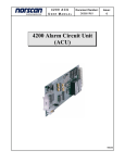
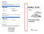
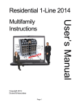
Service 2014
App
Copyright 2013
Durand & Associates
Page 1
d
e
v
ro
User’s Manual
Single Family
Instructions
SERVICE 2014
COPYRIGHT 2013 - DURAND & ASSOCIATES
This software and manual are protected by Federal Copyright Laws and may not be copied or
duplicated for the purpose of resale or distribution. A registered user may copy the template files
for their own personal use provided they retain sole possession of such copies.
The Service 2014 software is a spreadsheet template software program for calculating main service
panel size, feeder sizes and single family 1-Line drawings. The Service 2014 software is for reference
purposes only, and Durand & Associates cannot assume any responsibility for the accuracy of the
program contents. In using this program the user agrees to hold harmless and wave all claims against
Durand & Associates.
SOFTWARE REQUIREMENTS
Service 2014 was created with Microsoft Excel 97. To use these templates you must have Microsoft
Excel, Version 97 or later, installed on your computer.
Page 2
SINGLE FAMILY TEMPLATE
To use the single family template start your Excel program and select File Open.
Then navigate to the “Service 2014” folder.
Double click on the “Service 2014” folder which will display the folder’s contents.
Then double click on the “Single Family” to open the template.
Page 3
Once the template is open, use the “File Save As” command to save the file as a new project.
Excel 2003
Excel 2007
Then enter the new
project name.
Page 4
TABS
Located at the bottom of the screen are 2 tabs. One marked Input and the other marked Calcs.
The Input tab is used to enter your project’s information.
The Calcs tab is used to view and print your load calculations.
GENERAL ENTRIES
CODE YEAR
Select 2002, 2005, 2008, 2011, or 2014
DISPLAY 1-LINE
This will turn on or off the 1-Line drawing on the load calcs.
OVERHEAD / UNDERGROUND
Selecting overhead will display an overhead service on the
1-Line, and selecting underground will display an under
ground conduit on the 1-Line.
METER MAIN PANEL
METER - Will display a single meter.
METER MAIN - Will display a meter main combination.
METER MAIN PANEL - Will display a meter main & panel
combination.
MAIN PANEL
MAIN - Will display a separate main breaker.
MAIN PANEL - Will display a panel with a main breaker.
CONDUIT SIZE
Select none or the desired conduit size for your riser
or underground conduit.
CONDUIT TYPE
Select the type of conduit.
Page 5
GENERAL ENTRIES (continued)
VOLTAGE DROP CALCS
Select Yes or No. This will turn on or off the display of
voltage drop calculations.
HIGH VOLTAGE
Enter the highest voltage.
LOW VOLTAGE
Enter the lowest voltage.
FAULT CURRENT CALCS
Select Yes or No. This will turn on or off the display of
fault current calculations.
AVAILABLE FAULT CURRENT
If you are using an overhead service, enter the available
faultcurrent at the point of connection (service cap) to the
incoming power.
If you are using an underground service, enter the available
fault current at the meter.
PANEL NAME
Enter panel name.
PHASE
Select 1 or 3Y.
TOTAL SQUARE FOOTAGE
Enter the total square footage of the dwelling.
APPLIANCE CIRCUIT
Enter the number of appliance circuits. (Minimum 2)
LAUNDRY CIRCUITS
Enter the number of laundry circuits.
Page 6
GENERAL ENTRIES (continued)
FEEDER TYPE
Select CONDUIT, SER, or MC
LENGTH
Enter total length of wire from service cap to panel.
WIRE CU/AL
Select CU or AL.
WIRE TEMP
Enter wire temperature 60, 75, or 90.
MINIMUM AMPS
Enter the minimum amps.
% FACTOR
Enter the % factor. This will increase the design load
by the percentage. Example: If the calculated load is
90 amps and you enter 20%, the program will add
18 amps to the calculated load giving you a design
load of 108 amps.
GROUND WIRE Y/N
Enter YES or NO. This option only appears when
you are using a conduit feeder.
SELECT WIRE TYPE
Select wire type. This option only appears when
you are using a conduit feeder.
CONDUIT TYPE
Select conduit type. This option only appears when
you are using a conduit feeder.
VOLTAGE DROP %
Enter the % factor for voltage drop correction. This will
increase the wire size thus reducing voltage drop.
NOTE: Increasing the % factor forces the program to
increase the wire size thus reducing the voltage drop.
Page 7
GENERAL ENTRIES (continued)
RANGE(S) & OVEN(S)
Enter number of ranges, ovens, and KVA rating.
CLOTHES DRYER(S)
Enter number of dryers and KVA rating.
WATER HEATER(S)
Enter number of water heaters and KVA rating.
Enter heating & cooling loads listed above.
NOTE:
Displayed above is the heating & cooling loads for the 2008, 2011,
OR 2014 NEC. Other Code years will appear differently.
Page 8
GENERAL ENTRIES (continued)
Enter the description, number of units, and the amps for each item.
Enter the description, number of units, amps, and the phase for each item.
NOTE: Phase column only appears when using a 3-Phase panel.
Page 9
PRINTING
To print your load calculations click on the Calcs Tab.
Select the File Print Command
If the calculations print on more than one page, go to the “File Page Setup Command”
and reduce the percentage.
Page 10