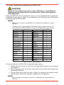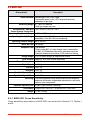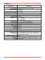
1
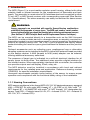
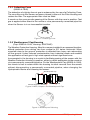
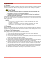
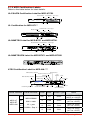
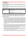
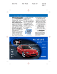
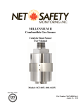
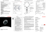
Operating Manual
Multi-Purpose Detector (MPD)
Table of Contents
Safety�����������������������������������������������������������������������������������������������������5
1. Introduction���������������������������������������������������������������������������������������8
1.1.1 Naming Conventions�������������������������������������������������������8
1.2 Principle of Operation��������������������������������������������������������������9
1.2.1 Catalytic Bead Sensor MPD-**-CB1��������������������������������9
1.3 Accessories������������������������������������������������������������������������������9
1.3.1 Collecting Cone�������������������������������������������������������������10
1.3.2 Weatherproof Cap����������������������������������������������������������10
1.3.3 Sample / Calibration Gas Flow Adaptor������������������������11
1.3.4 Gassing Point Assembly������������������������������������������������11
1.3.5 Duct Mount Kit���������������������������������������������������������������12
1.3.6 Filters�����������������������������������������������������������������������������12
2. Installation���������������������������������������������������������������������������������������13
2.1 Unpacking�������������������������������������������������������������������������������13
2.2 Sensor Orientation�����������������������������������������������������������������13
2.3 MPD Remote Mount���������������������������������������������������������������13
2.4 Wiring��������������������������������������������������������������������������������������14
2.4 Cable Connections�����������������������������������������������������������������14
2.5 Fitting Sensors�����������������������������������������������������������������������15
3. Fitting Accessories�������������������������������������������������������������������������16
3.1 Collecting Cone����������������������������������������������������������������������16
3.2 Weatherproof Cap������������������������������������������������������������������16
3.3 Sample/Calibration Gas Flow Adaptor���������������������������������16
3.4 Filters��������������������������������������������������������������������������������������16
3.5 Duct Mount Kit������������������������������������������������������������������������16
4. Maintenance������������������������������������������������������������������������������������17
4.1 General������������������������������������������������������������������������������������17
4.2 Cleaning����������������������������������������������������������������������������������17
5. Faults������������������������������������������������������������������������������������������������18
6. Functional Gas Test (Bump Test)��������������������������������������������������19
6.1 Sensor without Accessories ������������������������������������������������19
6.2 Sensor with Collecting Cone or Weatherproof Cap������������ 19
6.3 Sensor with Sample/Calibration Gas Flow Adaptor����������� 19
7. Calibration����������������������������������������������������������������������������������������20
7.1 Zero and Span Calibration for MPD Sensors with XNX
Universal Transmitter��������������������������������������������������������������20
7.2 Cross Calibration procedure for MPD-CB1�������������������������22
7.3 MPD-CB1 Flammable Sensor Operational Life�������������������24
7.4 Meter Multiplication Factors for MPD-IF1����������������������������24
8. Replacement Parts��������������������������������������������������������������������������25
MPD Operating Manual
3
8.1 MPD Catalytic Bead and IR Replacement Sensor Cartridges
�������������������������������������������������������������������������������������������������������25
8.2 Terminal Housings�����������������������������������������������������������������25
8.3 Maintenance Spares��������������������������������������������������������������25
8.4 MPD Calibration Gases���������������������������������������������������������26
9. Specifications����������������������������������������������������������������������������������26
9.1. General Specifications���������������������������������������������������������26
9.2 Performance Data������������������������������������������������������������������26
9.3 MPD-CB1���������������������������������������������������������������������������������28
9.2.1 MPD-CB1 Cross Sensitivity�������������������������������������������28
9.4 MPD-IV1����������������������������������������������������������������������������������29
9.5 MPD-IF1�����������������������������������������������������������������������������������30
9.6 MPD-IC1����������������������������������������������������������������������������������31
9.7 MPD Certifications by Part Number Series�������������������������32
9.7.1 MPD Certification Labels�����������������������������������������������33
10. Warranty�����������������������������������������������������������������������������������������34
11. EC Declaration of Conformity������������������������������������������������������36
4
MPD Operating Manual
Safety
»» Ensure that this Operating Manual is read and understood BEFORE installing, operating,
or maintaining the equipment.
»» Pay particular attention to Warnings and Cautions.
»» All document Warnings and Cautions are listed here and repeated where appropriate in
the relevant chapter(s) of this Operating Manual.
WARNINGS
»» Agency approvals are associated with specific Sensor/Housing combinations
rohibiting field upgrade of sensor types. The MPD part number, serial number, sensor
type and target gas should be provided when ordering replacement sensors (See
Section 8.1 MPD Catalytic Bead and IR Replacement Sensor Cartridges).
»» High off-scale readings may indicate an explosive concentration of gas.
»» To maintain safety standards, regular maintenance, calibration and operation of this
equipment by qualified personnel is essential. Read and understand this manual
completely before operating or servicing. If any further details are required which
do not appear in this manual contact Honeywell Analytics or their agent.
»» The Code of Practice regarding ‘Selection, Installation and Maintenance of Electrical
Apparatus for use in Potentially Explosive Atmospheres’ must be complied with at all
times. Refer to the appropriate local or national regulations relative to the installation
site. Elsewhere the appropriate local and/or national regulations should be used.
»» As some test gases may be hazardous, the Flow Adaptor outlet should exhaust into
a safe area.
»» Operators must be fully aware of the action to be taken if the gas concentration
exceeds an alarm level.
»» Before installing the sensors, isolate the power supply by disconnecting or removing
the associated control module from the installation.
»» Appropriate care should be taken when handling cylinders of compressed flammable
and toxic gases during calibration and bump testing.
MPD Operating Manual
5
CAUTIONs
»» To maintain safety standards, regular maintenance, calibration and operation of the
equipment by qualified personnel is essential.
»» Do not modify or alter the sensor construction as essential safety requirements
may be invalidated.
»» When replacing sensors, dispose of used sensors in accordance with local
disposal regulations. For more information on sensor disposal, contact your HA
Representative.
»» The catalytic detector element is resistant to catalyst poisons, however, abnormally
high concentrations of halogenated hydrocarbons, vapors of heavy metals or
compounds, some silicone compounds and sulfur compounds may cause loss of
sensitivity.
»» The MPD must never be used in conditions where there is insufficient oxygen to
totally oxidize the combustible gas. For most combustible gases, an oxygen level
of at least 15% is sufficient.
»» The sintered disc on the sensor assembly must be kept free from contaminants;
i.e. oil and dirt.
»» The sensitivity of catalytic sensors is impaired by silicone compounds. Do not expose
the sensors to silicones or silicone-based products.
»» The relevant site procedures must be obeyed at all times when opening the Terminal
Housing or removing the sensor in a hazardous areas.
»» The sensitivity of Catalytic Sensors is impaired by silicone compounds. Do not expose
to silicones or silicone based products.
»» Dismantling of a sensor or a sensor installation by other than authorized engineers
invalidates certification.
»» Upward pressure on the gassing nozzle of the Weatherproof Cap forces the nozzle
against the sinter. Rotation of the nozzle may damage the sinter if a filter is not fitted.
»» Direct gassing of the sensor via the nozzle on the Collecting Cone in wind speeds of
greater than 5 meters per second may cause errors.
»» The calibration procedure should only be performed by qualified personnel.
»» Before initial calibration allow the detector to stabilize for 30 minutes after applying
power. When in zero and span calibration mode the current output from the detector
is inhibited (e.g. default 2mA) to avoid false alarms.
»» Extended or frequent exposure to elevated concentrations of combustible gases
may affect sensor sensitivity. Verify sensor performance by frequent calibration.
»» Where the user calibrates any sensor using a different gas, responsibility for dentifying
and recording calibration rests with the user. Refer to the local regulations where
appropriate.
»» These (meter multiplication) factors only apply to gas concentrations expressed in
% Volume terms.
6
MPD Operating Manual
»» When using a linear cross reference factor the temperature compensation is based
upon propane, and there may be errors at temperatures away from the calibration
temperature.
»»
To maintain safety standards, regular maintenance, calibration and operation of the
equipment by qualified personnel is essential.
»»
Do not modify or alter the sensor construction as essential safety requirements
may be invalidated.
»» When replacing sensors, dispose of used sensors in accordance with local
disposal regulations. For more information on sensor disposal, contact your HA
Representative.
ATEX Temperature Code Ratings
»» Component gets no hotter than an operating temperature code of T4 when installed
according to the electrical specifications of Label ( Sch Drawing 1226E0309)
»» Maximum surface temperatures is less than 85°C when measured under normal
operating conditions for the Dust evaluation.
Important Notices
Every effort has been made to ensure the accuracy of the contents of our documents,
however, Honeywell Analytics can assume no responsibility for any errors or omissions in
our documents, or their consequences.
Honeywell Analytics can take no responsibility for installation and/or use of its equipment if
this is not done in accordance with the appropriate issue and/or amendment of the manual.
The user of this manual should ensure that it is appropriate in all details to the exact equipment
to be installed and/or operated. If in doubt, the user should contact Honeywell Analytics for
advice.
If further details are required which do not appear in this manual, contact Honeywell Analytics
or one of their agents.
MPD Operating Manual
7
1. Introduction
The MPD (Figure 1) is a serviceable explosion proof housing, offered with either
catalytic bead or infrared sensors for the measurement of flammable and toxic
gases. The assembly is constructed of 316 stainless steel and is supplied in either
¾ inch NPT or M25 thread versions with corresponding approvals (See Section
10 - Specifications). The sinter assembly can easily be removed for same sensor
replacement.
Warning:
Agency approvals are associated with specific Sensor/Housing combinations
prohibiting field upgrade of sensor types. The MPD part number, serial number,
sensor type and target gas should be provided when ordering replacement sensors
(See Section 8.1 MPD Catalytic Bead and IR Replacement Sensor Cartridges).
The MPD can be mounted directly to a transmitter such as the XNX Universal
Transmitter or other suitable device in a hazardous area, or remotely mounted to a
transmitter located in a non-hazardous area. For remote mounting, the detector is
fitted to an optional junction box. The ¾ NPT type is supplied with factory sealed
leads eliminating the need for a pour gland between the detector and the junction
box.
Optional accessories such as collecting cone, weatherproof cap or alternative
sampling systems can be installed to the MPD via the M40 external thread provided
on the sensor retainer. A M40 (female) to M36 (male) adaptor can be ordered,
offering additional accessory selections.
The presence of target gas is indicated via a millivolt electrical interface for all
sensor types via three wires. Two additional wires provide a digital interface for
the infrared version. When appropriately interfaced with a controller, the controller
can provide outputs such as display, 20mA, relay, etc.
The MPD detector must be installed in accordance with local and national
requirements for the installed area and application. Reference drawing number
1226E0351 for specific installation requirements.
Honeywell recommends periodic bump testing of the sensor to ensure proper
operation and compliance with the functional safety rating of the installation.
1.1.1 Naming Conventions
MPD sensor models are in the format MPD-XX-YYY. XX designates agency approval
(AM = ATEX/IEC Ex with male M25 thread, UT = UL/CSA or UL with male 3/4“
NPT thread, BT = UL/INMETRO with male 3/4“ NPT thread), YYY designates the
sensor Type (CB1 = Catalytic bead % LEL, IF1 = Infrared % LEL, IV1 = Infrared %
LEL CH4, IC1 = Infrared CO2).
8
MPD Operating Manual
3/4” NPT or M25 Threads
Sensor Cell
Sensor Retainer
and Locking Screw
2.080
[52.83]
3.016
[76.62]
1.875 [47.63]
(All dimensions reference)
2.016
[51.21]
20AWG Stranded Wire
7.5 [190.5] Nominal Length
Figure 1. Multi-Purpose Detector (MPD)
1.2 Principle of Operation
1.2.1 Catalytic Bead Sensor MPD-**-CB1
The CB1 sensor, catalytic bead type contains two elements which are heated by a
defined constant electrical current from the transmitter. One element is sensitive to
the presence of combustible gas, the second element compensates for changes in
temperature. When a combustible gas is present, the sensing element temperature
increases due to catalytic oxidation of the gas. The resistance of the element is
proportional to temperature and is proportional to a change to gas concentration.
The catalytic bead sensor provides the broadest range of combustible detection,
widest temperature range and performance approvals.
1.2.2 Infrared Sensor MPD-**-IF1, IV1, IC1
The IF1, IV1and IC1sensors use Non-Dispersive InfraRed (NDIR) Adsorption
techniques to detect a gas or family of gases. The sensor cells contain a long life
tungsten filament infrared light source, an optical cavity into which gas diffuses,
a dual temperature compensated pyroelectric infrared detector, and integral
semiconductor temperature sensor and electronics to process the signals from
the pyroelectric detector.
The IV1 sensor can measure methane concentration in the range of 0-5%Vol or
0-100%LEL. The IF1 sensor can measure propane concentration in the range of
0-100%LEL. The IC1 is used for carbon dioxide monitoring in the rage of 0-5% Vol.
1.3 Accessories
The following accessories are available for use with the sensors:
a.
b.
c.
d.
e.
f.
Collecting Cone (Figure 3).
Weatherproof Cap (Figure 4).
Sample/Calibration Gas Flow Adaptor (Figure 5).
Remote Gassing Port (Figure 6).
Duct Mount Kit (Figure 7).
Filters
MPD Operating Manual
9
1.3.1 Collecting Cone
(02000-A-1642)
The detection of a lighter than air gas is enhanced by the use of a Collecting Cone.
The cone fits onto the Sensor accessory thread in place of the Filter Housing and
retains the filter. The appropriate filter must be fitted.
A nozzle on the cone permits gassing of the Sensor with the cone in position. Test
gas is applied either direct to the nozzle or via a permanently connected pipe-line
when the Sensor is in an inaccessible location.
Figure 2. Collecting Cone
1.3.2 Weatherproof Cap/Housing
(Cap: 02000-A-1640, Housing: SPXCDWP)
The Weather Protection Housing, fitted to a sensor installed in an exposed location,
affords protection from driving rain from vertical to 30° below horizontal. When
mounted close to the ground, protection is afforded from heavy rain rebounding
off the ground. It also reduces contamination from industrial waste and enables
the application of test gas in high wind speeds without significant error.
Incorporated in the housing is a nozzle to facilitate gassing of the sensor with the
Weather Protection Housing in position, either by direct application to the nozzle or
via a permanently connected pipeline. On the Weatherproof Cap (02000-A-1640),
the nozzle is free to rotate within the housing to allow removal from the sensor
without disconnecting a permanently connected pipeline, when changing the
Hydrophobic Barrier and cleaning the sensor.
Weatherproof Cap
Sensor Accessory Thread
MPD
Figure 3. MPD, Adaptor and Weatherproof Cap
Figure 4. Weatherproof Housing
10
MPD Operating Manual
1.3.3 Sample / Calibration Gas Flow Adaptor
(1226A0411)
A Flow Adaptor provides a facility to allow sampling of a closed system by means
of two pipelines. The Flow Adaptor is fitted to the sensor accessory thread by a
locking ring that enables the Flow Adaptor to be removed without disconnecting
the pipeline. The Filter is retained by the Flow Adaptor and interfaces with a gasket
bonded to the Flow Adaptor. The Flow Adaptor ports are designed to be fitted
with 1/4 in (6mm) soft tubing.
The Flow Adaptor is also used to apply calibration gas to the sensor. See Section
7 - Calibration for further details on calibrating the detector.
Figure 5. Flow Adaptor / MPD with Flow Adaptor
1.3.4 Gassing Point Assembly
(1226A0354)
The Gassing Point Assembly assembly can be fixed in a convenient position and
permanently connected by suitable tubing to an inaccessible sensor, thus simplifying
the application of test gas when checking sensor calibration. A DIN Rail Mounting
Assembly (00785-A-0069) is available to enable five gassing point assemblies to
be mounted side by side.
Device Adapter
Tube Cap
1/4 in (6mm) I.D.
Teflon® Tubing
Mounting Bracket
Figure 6. Remote Gassing Port
MPD Operating Manual
11
1.3.5 Duct Mount Kit
The duct mounting kit (S3KDMK), combined with the MPD Interface Adaptor
(1226A0382), can accommodate the MPD to detect flammable gases in a duct
application. The duct mount kit includes the adaptor, gasket and required fasteners.
The MPD Interface Adaptor includes only the adaptor and requires the S3KDMKduct
mount kit.
1226A0382 MPD Adapter Ring
S3KDMK EC/MPD Duct Adapter Kit
Figure 7. Duct Mount Kit
1.3.6 Filters
In a clean atmosphere, and where no accessories are to be fitted, a filter is not
needed. It is however mandatory that a filter should be fitted to provide protection
appropriate to the environment and to complete the seal when a Weatherproof
Cap or Collecting Cone is fitted.
12
MPD Operating Manual
2. Installation
WARNING
The Code of Practice regarding ‘Selection, Installation and Maintenance of
Electrical Apparatus for use in Potentially Explosive Atmospheres’ must be
complied with at all times. Refer to the appropriate local and/or national regulations
relative to the installation site. Elsewhere the appropriate local and/or national
regulations should be used.
CAUTIONS
The catalytic detector element is resistant to catalyst poisons, however, abnormally
high concentrations of halogenated hydrocarbons, vapors of heavy metals or
compounds, some silicone compounds and sulfur compounds may cause loss of
sensitivity.
The MPD must never be used in conditions where there is insufficient oxygen to
totally oxidize the combustible gas. For most combustible gases, an oxygen level
of at least 15% is sufficient.
The sintered disc on the sensor assembly must be kept free from contaminants;
i.e. oil and dirt.
2.1 Unpacking
On receipt the equipment must be carefully unpacked, observing any instructions
printed on the packaging, and the contents checked for deficiencies and transit
damage.
2.2 Sensor Orientation
The sensor must be installed with the Sensor facing downwards. For MPD-BTIC1 and MPD-UT-IC1 performance approval, the supplied SPXCDWP weather
protector must be installed in order to meet published performance standards. In
environments requiring IP66 protection, the SPXCDWP must be fitted.
2.3 MPD Remote Mount
The MPD can be remote mounted using an approved junction box and
interconnecting conduit or cabling. The Junction Box and installation must be in
compliance with all local requirements for the area in which the unit is installed.
• The MPB UT versions must be installed a minimum of 5 1/4 turns into the
Junction box or Transmitter to maintain approval rating.
• The MPD Leads are factory sealed, which relieves the requirement for a
pour fitting between the junction box and sensor.
UL/CSA Aluminum Junction Box
2441-0022
ATEX/IEC Junction Box
00780-A-0100
Figure 8. Terminal Housings
MPD Operating Manual
13
2.4 Wiring
Note:
To maintain EMC integrity, wiring must be shielded by either an integral
shield or run through conduit or pipe. Shield should provide 90%
coverage.
The MPD Sensor must be operated from a transmitter supplied by a Class 2 Power
Supply.
For remote sensor installations, ensure the resistance of the wire is considered
in the interface of the sensor to maintain proper operation. For XNX the following
values should not be exceeded:
AWG
24
Metric Wire Gauge MPD CB1 Sensors MPD IC1, IV1 & IF1 Sensors
(distance in meters)
(distance in meters)
(mm2)
0.25
22
20
0.5
18
16
1.0
12 (47 ft.)
30 (97 ft.)
20 (65 ft.)
50 (162 ft.)
30 (97 ft.)
80 (260 ft.)
50 (162 ft.)
120 (390 ft.)*
80 (260 ft.)*
200 (650 ft.)*
* Frequency of zero calibration may increase due to the changes in wire resistance at different
temperatures.
2.4 Cable Connections
The sensor is connected by three wires:
Connections
Color Code
Sensitive
(S)
Brown
Non-sensitive
(NS)
Blue
Common
(01)
White
A 3-way terminal block is provided in the terminal enclosure to enable connection
to be made to the control unit. Earthing facilities are available if required.
NOTE
The black and red wires from the MPD are not used with the XNX mV Personality
Board. Insure they are properly isolated from live connections. DO NOT CUT.
14
MPD Operating Manual
2.5 Fitting Sensors
WARNING
Before installing the sensors, isolate the power supply by disconnecting or
removing the associated control module from the installation.
CAUTION
• The sensitivity of catalytic sensors is impaired by silicone compounds. Do not
expose the sensors to silicones or silicone-based products.
• The sintered disc on the sensor assembly must be kept free from containments;
i.e. oil and dirt.
• The relevant site procedures must be obeyed at all times when opening the
Terminal Housing or removing the sensor in a hazardous areas.
If replacing a sensor refer to CAUTION 1 in Section 4 - Maintenance.
To fit the MPD proceed as follows:
1. Remove the protection disc and fit the accessories as required. (Refer to
Section 3 - Fitting Accessories).
2. Isolate the power supply and wait for five minutes.
3. Remove the Terminal Housing lid.
4. Pass the cable into the Terminal Housing and fit the sensor to housing.
To comply with the certification requirements, a minimum of five threads
must be engaged.
5. Connect the sensor cable to the terminal block. (See the label adjacent
to the connector).
6. After mounting the Terminal Housing in the required location, connect the
associated Control Module wiring to the terminal block (see the label).
7. Replace and secure Terminal Housing lid.
8. If not already replaced by accessories, unscrew the Filter Housing, remove
the protection disc and replace Filter Housing and gasket.
NOTE
The Hydrophobic Barrier is retained in position by the Filter Housing, or
one of the accessories.
9. Connect power supply to the Sensor by reconnecting or replacing the
associated Control Module.
10.Calibrate the system as detailed in the equipment manual.
Note:
Calibration of the MPD is mandatory before the detector can be used for
gas monitoring. Refer to Section 7 - Calibration for the proper procedure.
MPD Operating Manual
15
3. Fitting Accessories
3.1 Collecting Cone
(02000-A-1462)
To fit the Collecting Cone to a sensor, carry out the following:
1.Remove the Filter Housing and gasket from the sensor.
2.Fit the Stainless Steel Filter.
3.Screw the Collecting Cone onto the sensor accessory thread and
tighten firmly by hand.
See Appendix A in the XNX Technical Manual for more Local HART Handheld.
information.
3.2 Weatherproof Housing
(SPXCDWP)
For FM 6340 performance approvals on MPD-BT-IC1 and MPD-UT-IC1,
SPXCDWP must be installed for IP66 compliance.
Note: Environmental conditions that compromise the IP66 protection
provided by the weather proof cover will extend published response
times. Safety protocols or maintenance procedures that consider these
environmental conditions are recommended specific to the installation.
3.3 Weatherproof Cap
(02000A1640)
To fit a Weatherproof Cap to a sensor carry out the following:
1. Remove the Filter Housing and gasket from the sensor.
2. Fit the Stainless Steel Filter.
3. Screw the Weatherproof Cap on to sensor accessory thread and
tighten firmly by hand.
3.4 Sample/Calibration Gas Flow Adaptor
(1226A0411)
To fit a Flow Adaptor to the sensor, carry out the following:
1. Remove the Filter Housing and gasket from the sensor.
2. Ensure that the Flow Adaptor is fitted with its gasket.
3. Apply a thin coating of anti-seize compound, such as light petroleum
grease, to the sensor accessory thread.
4. If required fit the Stainless Steel Filter, screw the Flow Adaptor on
to the sensor and tighten with a 47mm A/F spanner.
5. Set the sample flow rate to 0.5 ± 0.2 liters per minute, unless
otherwise directed in System installation instructions.
See Appendix B in the XNX Technical Manual for more Modbus. information.
3.5 Duct Mount Kit
The Duct Mounting Kit (S3KDMK), when combined with the MPD
Interface Adaptor (1226A0382), the Duct Mounting Kit can
accommodate the MPD to detect flammable gases in a duct application.
The kit includes the adaptor, gasket and required fasteners. The MPD
Interface Adaptor includes only the adaptor and requires the S3KDMK
Duct Mounting Kit.
16
MPD Operating Manual
4. Maintenance
4.1 General
Maintenance consists of cleaning the sensor and accessories, replacing gasket
and the Hydrophobic Barrier and gassing the sensor when testing the system.
CAUTIONS
• The sensitivity of Catalytic Sensors is impaired by silicone compounds. Do
not expose to silicones or silicone based products.
• Dismantling of a sensor or a sensor installation by other than authorized
engineers invalidates certification.
In the event of exposure to contaminant or prolonged exposure to high concentration
of gas, the sensor should be operated for 24 hours in a clean environment and
then recalibrated.
Note
If the sensor is found to be faulty, or cannot be calibrated, the sensor
cartridge is replaceable.
Dispose of in accordance with local disposal regulations. For more
information on sensor disposal, contact your HA Representative.
4.2 Cleaning
Sensor and accessories may be cleaned using an industrial grade of methanol,
providing the appropriate safety precautions are taken when handling this solvent.
4.3 Sensor Cell Replacement
Using Figure 8 as a guide, follow the procedure below:
1. Check that the label on the new sensor cell is the correct gas type.
2. Remove power from the transmitter.
3. Unscrew the weatherproof cover (if equipped), loosen the retainer locking
screw and unscrew the sensor retainer.
4. Remove the old sensor cell by pulling without twisting.
5. Replacement cartridges are designed to seal against an O-ring in the sensor
retainer. Verify O-ring described is in place prior to reassembly.
6. Slide the replacement cell into the MPD body taking care to align the tab
with the alignment slot, then press the cell firmly to seat it into the body.
7. Refit the sensor retainer, tighten until hex is flush with the body of the sensor.
8. Tighten the locking screw and refit the weatherproof cover (if equipped).
9. Recalibrate the detector following the procedures in Section 7.
MPD Operating Manual
17
Internal O-ring
(critical to performance times)
Cell Alignment Slot
Sensor Cell
IR or Cat Bead
Sensor Retainer
and Locking Screw
Figure 9. Replacing Plug In Sensor
5. Faults
The following table provides a list of possible faults related to the sensor together
with possible causes and remedies.
Fault
Cause/Remedy
Sensor reads non-zero all the time
Gas could be present, ensure there is no
combustible gas in the atmosphere.
Sensor reads non zero when no gas is present
Adjust the zero of the control system.
Sensor reads low when gas is applied
Adjust the span of the control system.
Sensor reads high when gas is applied
Adjust the span of the control system.
Sensor reads zero when gas is applied
• check the wiring.
• check that the dust protection cap has been
removed.
• check that the sinter is not obstructed.
• replace the sensor if poisoning is suspected.
In the event of exposure to contaminant, e.g. silicones or silicone based products,
or prolonged exposure to high concentration of gas, the sensor should be operated
for 24 hours in a clean environment and then recalibrated.
If the sensor is found to be faulty, or cannot be calibrated, the complete sensor
must be discarded and replaced.
18
MPD Operating Manual
6. Functional Gas Test (Bump Test)
6.1 Sensor without Accessories
Where there are no accessories fitted, it is recommended that a Flow Adaptor is
used when gassing the sensor. Where this is not possible, a suitable plastic bag
may be used.
6.2 Sensor with Collecting Cone or Weatherproof Cap
1. Using the rubber tubing, connect the test gas to the gassing nozzle or to
the permanently connected tubing if fitted.
CAUTION
• Upward pressure on the gassing nozzle of the Weatherproof Cap forces the
nozzle against the sinter. Rotation of the nozzle may damage the sinter if a
filter is not fitted.
• Direct gassing of the sensor via the nozzle on the Collecting Cone in wind
speeds of greater than 5 meters per second may cause errors.
2. Set the flow rate to 1.5 ± 0.1 liters per minute and test the system in
accordance with the instructions in the appropriate system equipment
manual.
3. On completion, shut off the test gas and disconnect the rubber tubing.
6.3 Sensor with Sample/Calibration Gas Flow Adaptor
1. Shut off the sample flow to the Flow Adaptor.
2. Disconnect the input pipeline from the input nozzle of the Flow Adaptor.
3. Using the rubber tubing, connect the test gas to the Flow Adaptor input
nozzle.
4. Set the flow rate to 0.5 ± 0.2 liters per minute and test the system in
accordance with the instructions in the appropriate system equipment
manual.
5. On completion, shut off the test gas and disconnect the rubber tubing.
6. Reconnect the input pipeline to the Flow Adaptor input nozzle and restore
the sample flow.
MPD Operating Manual
19
7. Calibration
CAUTION
The calibration procedure should only be performed by qualified personnel.
NOTE:
Honeywell Analytics recommends that the maximum calibration interval
be 6 months or in accordance with customer site procedures, whichever
is sooner to assure the highest level of safety. Correct operation of each
sensor/detector should be confirmed with test gas of known concentration
before each use.
7.1 Zero and Span Calibration for MPD Sensors with XNX Universal Transmitter
CAUTION
Before initial calibration allow the detector to stabilize for 30 minutes after
applying power. When in zero and span calibration mode the current output from
the detector is inhibited (e.g. default 2mA) to avoid false alarms.
Extended or frequent exposure to elevated concentrations of combustible gases
may affect sensor sensitivity. Verify sensor performance by frequent calibration.
This section describes how to calibrate MPD sensors fitted to the XNX Universal
Transmitter.
The calibration adjustments are made on the XNX’s display and gassing is performed
at the sensor (this may be locally or remotely located).
The following equipment is required:
• Sample/Calibration Gas Flow Adaptor (Part No: 1226A0411)
• Test gas
• Regulator
NOTE
Zero gas and Span gas should be at roughly the same humidity levels to
avoid erroneous cell responses.
1. At the MPD, remove the Weatherproof Cap if equipped.
2. Fit the Flow Adaptor onto the MPD.
Figure 10. Flow Adaptor
Reverse the cap removal procedure. The following diagram shows the Flow Adaptor
accessory fitted to the MPD.
20
MPD Operating Manual
Figure 11. MPD with Flow Adaptor
NOTE
The Gas Calibration menu is for both Zero and Span Calibration.
3. Connect the Flow Adaptor (using either gas pipe) to the regulated cylinder
containing a known concentration of the target gas at approximately the
sensor alarm point (e.g. 50% LEL Methane in air).
WARNING
As some test gases may be hazardous, the Flow Adaptor outlet should exhaust
into a safe area.
4. Follow the procedure in Section 3.2.1 of XNX Universal Transmitter Technical
Manual for both Zero and Span calibrations.
5. Apply the target gas to the sensor. Pass the gas through the Flow Adaptor
at a rate of 0.5l/m ± 0.2l/m.
NOTE:
Sensors should be calibrated at concentrations representative of those to
be measured. It is always recommended that the sensor is calibrated with
the target gas it is to detect.
CAUTION
Where the user calibrates any sensor using a different gas, responsibility for
identifying and recording calibration rests with the user. Refer to the local
regulations where appropriate.
6. Ensure that the sensor and the vicinity around it are clear all traces of
the calibration gas before continuing. This is to avoid triggering spurious
alarms. If calibration fails at any point discard the cartridge and replace
with a new one.
7. Remove the test equipment, refit the weatherproof cap to the sensor (if
previously removed for the test) and return the system to normal operation.
MPD Operating Manual
21
7.2 Cross Calibration procedure for MPD-CB1
CAUTION
Where the user calibrates any sensor using a different gas, responsibility for
identifying and recording calibration rests with the user. Refer to local regulations
where appropriate.
When the MPD-CB1 Combustible LEL sensor is to be calibrated with a gas which
is different to the gas or vapor to be detected, the following cross calibration
procedure should be followed:
NOTE
• Table 1 lists the gases according to the reaction they produce at a given
detector.
• An eight star (8*) gas produces the highest output, while a one star (1*)
gas produces the lowest output. (These are not applicable at ppm levels.)
Gas
Star Rating
Gas
Star Rating
Acetone
4*
Hexane
3*
Ammonia
7*
Hydrogen
6*
Benzene
3*
Methane
6*
Butanone
3*
Methanol
5*
Butane
4*
Nonane
2*
Butyl acetate
1*
MIBK
3*
Butyl acrylate
1*
Octane
3*
Cyclohexane
3*
Pentane
4*
Cyclohexanone
1*
Propane
5*
Diethyl ether
4*
Propan-2-ol
4*
Ethane
6*
Styrene
2*
Ethanol
5*
Tetra hydrafuran
4*
Ethyl acetate
3*
Toluene
3*
Ethylene
5*
Triethylamine
3*
3*
Xylene
2*
Heptane
Table 1. Star Rating of Gases
To cross calibrate the MPD-CB1 combustible gas sensor:
1. Obtain the star rating for both the test gas and the gas to be detected
from Table 1.
2. Set the gas selection to the star rating which is the same star rating of the
gas being detected.
3. These values may then be used in Table 2 to obtain the required meter
setting when a 50% LEL test gas is applied to the detector.
NOTE
These settings must only be used with a calibration gas concentration of
50% LEL.
22
MPD Operating Manual
* Rating of
Calibration
Gas
* Rating of Gas to be Detected
8*
7*
6*
5*
8*
50
62
76
95
-
7*
40
50
61
76
95
-
6*
33
41
50
62
78
95
-
5*
26
33
40
50
63
79
95
-
4*
-
26
32
40
50
63
80
95
3*
-
-
26
32
40
50
64
81
2*
-
-
-
25
31
39
50
64
1*
-
-
-
-
25
31
39
50
4*
3*
2*
1*
-
-
Table 2. Meter Settings
4. If a sensor is to be used to detect a gas other than that for which it was
calibrated, the required correction factor may be obtained from Table 3.
The meter reading should be multiplied by this number in order to obtain
the true gas concentration.
Sensor
calibrated to
detect
Sensor Used To Detect
8*
7*
6*
5*
4*
3*
2*
1*
8*
1.00
1.24
1.52
1.89
2.37
2.98
3.78
4.83
7*
0.81
1.00
1.23
1.53
1.92
2.40
3.05
3.90
6*
0.66
0.81
1.00
1.24
1.56
1.96
2.49
3.17
5*
0.53
0.66
0.80
1.00
1.25
1.58
2.00
2.55
4*
0.42
0.52
0.64
0.80
1.00
1.26
1.60
2.03
3*
0.34
0.42
0.51
0.64
0.80
1.00
1.27
1.62
2*
0.26
0.33
0.40
0.50
0.63
0.79
1.00
1.28
1*
0.21
0.26
0.32
0.39
0.49
0.62
0.78
1.00
Table 3. Meter Multiplication Factors
NOTE
Since combustible sensors require oxygen for correct operation, a mixture
of gas in air should be used for calibration purposes. Assuming average
performance of the sensor, the sensitivity information in Tables 1 to 3 is
normally accurate to +20%.
EXAMPLE
If target gas to be detected is Butane and the calibration gas available is Methane
(50% LEL):
1. Look up the star rating for each gas in Table 1: Butane 4* and Methane 6*.
2. Check the meter settings for 50% LEL calibration gas in Table 2; in this
case, 78.
3. The meter should therefore be set to 78% to give an accurate reading for
Butane using 50% LEL Methane as a calibration gas.
NOTE
It is important to calibrate the sensor at the approximate alarm levels to
allow for non-linearity of the sensors at gas concentrations above 80% LEL.
MPD Operating Manual
23
7.3 MPD-CB1 Flammable Sensor Operational Life
The pellistors used in the flammable gas sensor can suffer from a loss of sensitivity
when in the presence of poisons or inhibitors, e.g. silicones, sulfides, chlorine, lead
or halogenated hydrocarbons. The pellistors are poison resistant to maximize the
operational life of the flammable sensor. A typical operating life, subject to the
presence of poisons/inhibitors is 36 months.
7.4 Meter Multiplication Factors for MPD-IF1
It is possible to apply a linear cross reference factor to the output of a sensor
characterized for propane and achieve the results shown in the graph below.
Reasonable accuracy is maintained to at least the 50% LEL equivalent values of
the cross-referenced gases.
Figure 12. MPD-IF1 (Propane) Sensor with linear cross-reference factor applied
Use the following multiplying factors to cross-refer to the propane reading:
Gas
Multiplication
Factor
Ethylene
5.43
nButane
0.98
nPentane
0.93
Table 4. Multiplying Factors
CAUTION
• These factors only apply to gas concentrations expressed in % Volume terms.
• When using a linear cross reference factor the temperature compensation is
based upon propane, and there may be errors at temperatures away from the
calibration temperature.
NOTE
Honeywell Analytics recommends that users verify the accuracy of
their instruments using test gases wherever possible. Cross-referred
measurements should be used as a guide only, not as absolute values.
24
MPD Operating Manual
8. Replacement Parts
8.1 MPD Catalytic Bead and IR Replacement Sensor Cartridges
Sensor
Type
Target Gas
Cartridge
Part No
Maximum
Range
Selectable
Range
Increment
Default
Range
MPD-IC1
Carbon
Dioxide
1226-0301
5.00 %Vol
1.00 to 5.00 %Vol
1.00 %Vol
MPD-IV1
Methane
1226-0299
5.00 %Vol or
0-100%LEL
1.00 to 5.00 %Vol
or 0-100%LEL
n/a
MPD-IF1
Flammables 1226-0300
100 %LEL
20 to 100 %LEL
10 %LEL
100 %LEL
MPD-CB1 Flammables 1226A0359
100 %LEL
20 to 100 %LEL
10 %LEL
100 %LEL
5.00 %Vol
0-100%LEL
Note:
When ordering replacement MPD sensor cartridges, the replacement
cartridge MUST be the same type as factory configured. Substituting a
different cartridge will void agency certification.
8.2 Terminal Housings
Note
When ordering replacements, always quote the complete part number.
Where a part number is not listed or known, state type, material, cable
entry size and other relevant details.
Part Number
Description
2441-0022
UL/CSA Aluminum Junction Box (2 entries)
2110B2103
UL/CSA Stainless Steel Junction Box (2 entries)
00780-A0100 ATEX/IEC Junction Box (3) M20, (1) M25 entries.
Cable Entry Thread
3/4 NPT
3/4 NPT
M20/M25
8.3 Maintenance Spares
When ordering replacements, always quote the complete part number.
Part Number
Description
1226A0354
Remote Gassing Port
02000-A-1642
Collecting Cone
1226A0411
Sample Flow Adaptor
02000A1640
Weatherproof Cap
S3KDMK
Duct Adaptor Kit
1226A0382
MPD Duct Interface Adaptor (S3KDMK req’d)
SPXCDWP
Weatherproof Housing
MPD Operating Manual
25
8.4 MPD Calibration Gases
Cal Gas Range Cal Gas P/N
Cal Gas Description
MPD-IC1
Sensor Type
Carbon Dioxide
Target Gas
1.50 to 3.5 %Vol
Contact HA
2.5 %VOL CO2 in air
MPD-IV1
Methane
1.50 to 3.5 %Vol
GFV352
2.5 %VOL CH4 in air or LEL
MPD-IF1
Flammables
30 to 70 %LEL
GFV406
1 %VOL C3H8 in air
MPD-CB1
Flammables
30 to 70 %LEL
GFV352
50 %LEL CH4 in air
9. Specifications
9.1. General Specifications
Electrical
Sensor
Operating Voltage
MPD**-CB1
2.9
0.2
MPDXX-I**
4
0.08
Power Consumption
Negative going signal with concentration
5-20 AWG (0.52 mm2) by 7: (178 mm) long
Connection
Construction
2.2” (56 mm) D x 3” (76 mm) L
Dimensions
Weight
1.2 lbs. (0.54 kg)
Material
316 stainless steel
MPD-UT*** (factory sealed): 3/4” male N.P.T.
MPD-BT*** (factory sealed): 3/4” male N.P.T.
MPD-AM***: M25 male
Environmental - Operating
IP66
IP Rating
Port Types
MPD**-CB1: -40°C to +65°C (-40°F to +149°F)
MPD**-I**: -20°C to +50°C (-4°F to +122°F)
see sections 9.3 - 9.6
Temperature
Humidity
Environmental - Storage
Temperature
Humidity
-40°C to +65°C / -40°F to +149°F
0 to 99% RH non-condensing
9.2 Performance Data
26
Sensor
Type
Gas
Response
Time
(T50) sec
Response
Time
(T90) sec
Accuracy
(% of full scale or
% of applied gas)
MPD-IC1
Carbon Dioxide
<30
<70
±5%FS or ±15%
MPD-IV1
Methane
<15
<30
±5%FS or ±15%
MPD-IF1
Propane
<15
<30
±5%FS or ±15%
MPD-CB1 Methane
<15
<30
±5%FS or ±15%
MPD Operating Manual
Sensor
Type
Drift Over
Time
Operating Temperature
Min
Max
Operating
Pressure
Operating
Air Speed
MPD-IC1
< 3%/yr
-20°C / -4°F
+50°C / 122°F
80kPa ~ 110kPa
0 ~ 6m/sec
MPD-IV1
< 3%/yr
-20°C / -4°F
+50°C / 122°F
80kPa ~ 110kPa
0 ~ 6m/sec
MPD-IF1
< 3%/yr
-20°C / -4°F
+50°C / 122°F
80kPa ~ 110kPa
0 ~ 6m/sec
MPD-CB1
< 3%/yr
-40°C / -40°F +65°C / 149°F
80kPa ~ 120kPa
0 ~ 6m/sec
NOTES
• Data taken at 20-25°C. Contact HA for any additional data or details.
• Response times may increase at lower temperatures.
• Data represents typical values without optional accessories attached
(MPD**IC1 with SPXCDWP. T5<60, T90<120).
• Note: Environmental conditions that compromise the IP66 protection provided
by the weather proof cover will extend published response times. Safety
protocols or maintenance procedures that consider these environmental
conditions are recommended specific to the installation.
• System conditioning may be required to achieve stated results. Contact HA
for details.
• Performance figures are measured using a sample humidity of 50% RH.
• Performance figures are measured between 40 and 60% of full scale.
• Performance figures are measured by test units calibrated at 50% of full scale.
MPD Operating Manual
27
9.3 MPD-CB1
Characteristic
Description
Gases Detected: Methane gas in the %LEL range.
Combustible gases in the %LEL range with sensitivity
dependent on gas type.
Measuring Range: 0 – 100%LEL Methane
Other gas ranges may vary.
Environmental - XNX MPD -40°C to +65°C/-40°F to +149°F
Sensor Storage Temperature
Operating Temperature Range: -40°C to +65°C
Operating Humidity Range: Continuous: 20 to 90% RH non-condensing
Intermittent: 10 to 99% RH non-condensing
Operating Pressure Range: 80 to 120 kPa
Warm Up Time: 10 minutes
Response Time: <30 seconds
Time to reach 90% of a step change in gas concentration
of 100% of FS Methane measured in accordance with the
Canadian Standards Association (CSA) method of testing.
Voltage Range: 2.42V to 2.90V Bridge (at 200mA drive current)
Drive Current: 200mA ± 1mA (From control equipment)
Power Consumption: <600mW
Signal Output: mV Bridge
Linearity: <±5% FS
Accuracy: <±5% FS
Zero Stability with Time: <±3% FS/year
Span Stability with Time: <±5% FS/year
Poisoning: The sensing elements may become inactive after extensive
exposure to silicones, halogenated hydrocarbons, and heavy
metal or sulfur compounds.
Expected Operating Life: 5 years (Typical without Poisoning)
Dimensions: 2.080 in Dia x 3.016 in L / 52.83 mm Dia x 76.62 mm L
Weight: 1.2 lbs / 544.3g
9.2.1 MPD-CB1 Cross Sensitivity
Cross sensitivity information for MPD-CB1 can be found in Section 7.2, Tables 1
and 3.
28
MPD Operating Manual
9.4 MPD-IV1
Characteristic
Description
Gases Detected: Methane gas in the %Vol and %LEL range.
Measuring Range: 0 – 5.00%Vol
0 – 100%LEL
Operating Temperature Range: -20°C to +50°C
Operating Humidity Range: 0 to 95% RH non-condensing
Operating Pressure Range: 80 to 110 kPa
Warm Up Time: 3 minutes
Response Time: T90 = <30 seconds
Time to reach 90% of a step change in gas concentration of
100% of FS Methane
Voltage Range: 3.0V ~ 5.0V (From control equipment)
Drive Current: 75mA ~ 85mA (From control equipment)
Power Consumption: <500mW
Signal Output: mV Bridge
Linearity: <±5% FS
Accuracy: <±5% FS
Zero Stability with Time: <±3% FS/year
Span Stability with Time: <±5% FS/year
Span Stability with <±10% of reading up to 50% FSD, ±15% of reading from
Temperature: 50% to 100% FSD or 2% FSD whichever is greater over the
operating temperature range.
Expected Operating Life: 5 years
Dimensions: 2.080 in Dia x 3.016 in L / 52.83 mm Dia x 76.62 mm L
Weight: 1.2 lbs / 544.3g
MPD Operating Manual
29
9.5 MPD-IF1
Characteristic
Description
Gases Detected: Propane gas in the %LEL range.
Combustible gases in the %LEL range with sensitivity
dependent on gas type.
Measuring Range: 0 – 100%LEL Propane
Other gas ranges may vary.
Operating Temperature Range: -20°C to +50°C
Operating Humidity Range: 0 to 95% RH non-condensing
Operating Pressure Range: 80 to 110 kPa
Warm Up Time: 3 minutes
Response Time: T90 = <30 seconds
Time to reach 90% of a step change in gas concentration of
100% of FS Propane
Voltage Range: 3.0V ~ 5.0V (From control equipment)
Drive Current: 75mA ~ 85mA (From control equipment)
Power Consumption: <500mW
Signal Output: mV Bridge
Linearity: <±5% FS
Accuracy: <±5% FS
Zero Stability with Time: <±3% FS/year
Span Stability with Time: <±5% FS/year
Span Stability with <±10% of reading up to 50% FSD, ±15% of reading from
Temperature: 50% to 100% FSD or 2% FSD whichever is greater over the
* May not be applicable when using gas crossoperating temperature range.
reference factors
Expected Operating Life: 5 years
Dimensions: 2.080 in Dia x 3.016 in L / 52.83 mm Dia x 76.62 mm L
Weight: 1.2 lbs / 544.3g
30
MPD Operating Manual
9.6 MPD-IC1
Characteristic
Description
Gases Detected: Carbon Dioxide in the %Vol range.
Measuring Range: 0 – 5.00%Vol
Operating Temperature Range: -20°C to +50°C
Operating Humidity Range: 5 to 95% RH non-condensing
Operating Pressure Range: 80 to 110 kPa
Warm Up Time: 3 minutes
Response Time: T50 = <30 seconds, T90 = <70 seconds
with SPXCDWP, T50 = <60 seconds, T90 = <120 seconds
Time to reach 50% and 90% of a step change in gas
concentration of 100% of FS Carbon Dioxide
Voltage Range: 3.0V ~ 5.0V (From control equipment)
Drive Current: 75mA ~ 85mA (From control equipment)
Power Consumption: <500mW
Signal Output: mV Bridge
Linearity: <±5% FS
Accuracy: <±15% of reading
Zero Stability with Time: <±3% FS/year
Span Stability with Time: <±5% FS/year
Span Stability with <±10% of reading up to 50% FSD, ±15% of reading from
Temperature: 50% to 100% FSD or 2% FSD whichever is greater over the
* May not be applicable when using gas
operating temperature range.
cross-reference factors
Expected Operating Life: 5 years
Dimensions: 2.080 in Dia x 3.016 in L / 52.83 mm Dia x 76.62 mm L
Weight: 1.2 lbs / 544.3g
MPD Operating Manual
31
9.7 MPD Certifications by Part Number Series
T
MPD-BTIC1
MPD-UTIC1 (IR CO2)
T
MPD-BTIV1
MPD-UTIF1 (IR Flam)
T
MPD-BTIF1
MPD-UTIV1 (IR Methane)
T
MPD-BTCB1
MPD-UTCB1 (Cat Bead)
C-UL
UL/CSA Certifications by Part Number Series
T
T
T
T
Hazardous Location - UL
UL 1203
CSA
Hazardous Location - CSA
CAN/CSA C22.2 No. 30 M-1986
T
CSA C22.2 No. 152
FM
Listed
N/A N/A
T
N/A N/A N/A N/A
Performance with XNX Transmitter XNXUT*V-*****
T
N/A N/A N/A N/A N/A N/A N/A
Performance with XNX Transmitter XNXUT*V-*****, XNXBT*V-*****
FM 6310 / 6320
FM 6430
T
N/A N/A N/A
N/A N/A N/A
T
T
N/A N/A N/A
N/A N/A N/A
T
MPD-AMCB1 (Cat Bead)
MPD-AMIV1 (IR Methane)
MPD-AMIF1 (IR Flam)
MPD-AMIC1 (IR CO2)
CE Mark
EMC
Compliance
ATEX/IEC Certifications by Part Number Series
B
B
B
B
Electromagnetic & Safety
EU directive 2004/108/EC
EN 50270:2006
B
B
B
B
EU directive 94/9/EC
M
M
M
M
CENELEC EN 60079-0:2012
M
M
M
M
CENELEC EN 60079-1:2007
M
M
M
M
CENELEC EN 60079-29
M
M
M
M
CENELEC EN 60079-31:2009
M
M
M
M
IEC 60079-0, 6th Ed
M
M
M
M
IEC 60079-1 6th Ed
M
M
M
M
IEC 60079-31
M
M
M
M
IECEx
ATEX/
DEMKO
Hazardous Location
Legend: M = M25 threaded Adaptors, T = 3/4 NPT threaded Adaptors, B = Both 3/4 NPT and M25,
N/A = Not Approved or Not Applicable
32
MPD Operating Manual
CSA
Class I, Division 1
Groups B,C,D
UL
Class I Division 1
Groups B,C, D
Class II Division 1
UL/Demko
INMETRO
FM
Approvals
Groups F & G
AEx d IIB+ H2 T4
-40 °C ≤Tamb≤ 65°C
AEx d IIB+ H2 T4
-20 °C ≤Tamb≤ 50°C
Ex D IIB + H2 IP66
-40°C ≤ Ta ≤ 65°C
l
II 2 D Ex tb IIIC Db IP 66
MPD Operating Manual
MPD-AMIC1
l l l l l l l l
l l l l l l l l
l
l
l
l
l
l l l
-20 °C ≤ Ta ≤ 50°C l
II 2 G Ex d IIB +H2 Gb
(Tamb -20 °C to 50 °C) IP66
MPD-AMIV1
l
Ex D IIB + H2 IP66
II 2 G Ex d IIB +H2 Gb
(Tamb -40 °C to 65 °C) IP66
MPD-AM1F1
MPD-AMCB1
MPD-BTIC1
MPD-BTIV1
MPD-BT1F1
MPD-BTCB1
MPD-UTIC1
MPD-UTIV1
MPD-UT1F1
Description
MPD-UTCB1
9.7.1 MPD Hazardous Area Approvals
l
l l l
l l l l
33
9.7.2 MPD Certification Labels
Refer to the table below for label details.
UL/CSA/FM Certification Label for MPD-UTCB1
As to Fire and Explosion Only
Enclosure for use in Hazardous Areas
CAUTION: To Prevent Ignition of Hazardous
Atmospheres disconnect power before servicing
Leads Factory Sealed
SSI F I E
LA
D
FM Approved to Class I, Zone 1,
AEx d IIB + H2 T4 -40°C≤Tamb≤+65°C
and FM6310/6320 with XNX
Universal Transmitter See Manual
C
Model Number Serial Number Sensor Type
R
39YC
CSA to CII, Div.1 Grps B, C, D, Zone 1 IIB +H2
C22.2 No 152 for use with XNX Transmitter
Keep Sinter Ass'y tightly closed while energized
Leads Factory Sealed
Vmax
Tamb
Imax
UL Certification for MPD-UT1**
SS I F I E
LA
D
C
Model Number Serial Number Sensor Type
As to Fire and Explosion Only Enclosure for use in Hazardous Areas
CAUTION: To prevent ignition of Hazardous Atmospheres disconnect
power before servicing.
Leads Factory Sealed
R
39YC
Tamb
Vmax Imax
UL/INMETRO Label for MPD-BTIF1 and MPD-BTIV1
Model Number Serial Number Sensor Type
Ex d IIB + H2 Gb IP66
a
Tamb
Vmax
Imax
UL/INMETRO/FM Label for MPD-BTIC1 and MPD-BTCB1
ATEX Certification Label for MPD-AM-****
Model Number
ATEX Certificate Number
Equipment Protection Level
Gas Group
IECEx Certificate Number
Protection Concept
Serial
Number
Tamb
Sensor Type
ATEX Coding
IECEx UL 09.0012U
-READ AND UNDERSTAND MANUAL PRIOR TO
INSTALLATION AND OPERATION
-THREAD TYPE M25
User Warnings/Cautions
Serial Number
ATEX Notified Body
Vmax
Identification Number
Serial Number
Vmax
Imax
Ingress
Protection
Manufacturer
Name and Address
Imax Sensor Type
2.9
0.2
%LEL
-40°C to +65°C
(-40°F to +149°F)
WW = week
4
0.08
%LEL
-20°C to +50°C
(-4°F to +122°F)
YY = year
4
008
CH4
-20°C to +50°C
(-4°F to +122°F)
4
0.08
CO2
-20°C to +50°C
(-4°F to +122°F)
CB1
WWYYNNNN
MPD-UT
MPD-BT
MPD-AM
IF1
IV1
NNNN = Seq. #
IC1
34
Tamb
MPD Operating Manual
10. Warranty
Warranty Statement
All products are designed and manufactured to the latest internationally recognized
standards by Honeywell Analytics under a Quality Management System that is
certified to ISO 9001.
The Multi-Purpose Detector (MPD) is warranted by Honeywell Analytics (herein
referred to as ‘HA’) to be free from defects in material or workmanship under normal
use and service for:
Device
Warranty Terms
Multi-Purpose Detector 12 months from date of commissioning by an approved Honeywell
(MPD)
Analytics representative
or
18 months from date of shipment from Honeywell Analytics
Whichever is sooner
Service in the field or at the customer’s premises is not covered under these
warranty terms. Time and travel expenses for on-site warranty services will be
charged at Honeywell Analytics’ normal billing rates. Contact your Honeywell
Analytics Service Representative for information on Service Contracts.
Warranty Conditions
1. The Honeywell Analytics (HA) Limited Product Warranty only extends to the
sale of new and unused products to the original buyer where purchased
from HA or from a HA authorized distributor, dealer or representative. Not
covered are: consumable items such as dry-cell batteries, filters and fuses
or routine replacement parts due to the normal wear and tear of the product;
any product which in HA’s opinion has been altered, neglected, misused or
damaged by accident or abnormal conditions of operation, handling, use or
severe sensor poisoning; defects attributable to improper installation, repair
by an unauthorized person or the use of unauthorized accessories/parts on
the product.
2. Any claim under the HA Product Warranty must be made within the warranty
period and as soon as reasonably possible after a defect is discovered. If a
Warranty claim is being sought it is the responsibility of the buyer to obtain a
Service Event number (SE#) from HA and if practical return the product clearly
marked with the SE# and a full description of the fault.
3. HA, at its sole discretion, may elect to send replacement goods to buyer prior
to receipt of the defective goods. Buyer agrees to return defective goods with
in 30 days or to pay for the replacement goods.
4. Buyer is responsible for transportation costs from the buyer’s location to HA.
HA is responsible for transportation costs from HA’s location to the buyer.
MPD Operating Manual
35
5. If in the case of a fixed installation or when it is not practical to return the
product, the buyer should submit a claim to HA Service Department. A service
engineer will attend on site on a day rate basis. Where a valid warranty claim
is identified, the faulty product will be repaired or replaced free of charge. A
warranty claim will be accepted if all conditions contained within this Warranty
are met.
6. When, in the opinion of HA, a warranty claim is valid, HA will repair or replace
the defective product free of charge and send it or any replacement back
to the buyer. If, in the opinion of HA the warranty claim is not valid, HA will,
at the option of the buyer, return the unit unaltered at the buyer’s expense,
repair the unit at the then prevailing rates, replace the unit with an appropriate
replacement item at the then prevailing price, or discard the unit. HA reserves
the right to charge for any attendance by its service engineer at the usual rates
in force at the time the claim was received.
7. In no event shall HA’s liability exceed the original purchase price paid by the
buyer for the product.
Consumer Claims
If you purchased your HA product as a consumer, the above warranty conditions
do not affect your rights under any applicable consumer protection legislation.
Honeywell Analytics reserves the right to change this policy at any time. Contact
Honeywell Analytics for the most current warranty information.
36
MPD Operating Manual
11. EC Declaration of Conformity
EC Declaration of Conformity
The undersigned of
For and on behalf of the importer
Honeywell Analytics Inc
405 Barclay Boulevard
Lincolnshire, Illinois 60069
Life Safety Distribution AG
Javastrasse 2
8604 Hegnau
Switzerland
United States
Declares that the products listed below
MPD Adaptor
The MPD (Multi Purpose Detector) is a serviceable flameproof and dust ignition protected housing, offered
with either Catalytic Bead or Infrared sensors for the measurement of flammable and toxic gasses.
Are in conformity with the provisions of the following European Directive(s), when installed, operated, serviced and maintained in
accordance with the installation/operating instructions contained in the product documentation:
2004/108/EC
EMC Directive
94/9/EC
ATEX Directive – Equipment for use in Potentially Explosive Atmospheres
And that the standards and/or technical specifications referenced below have been applied or considered:
Standard
EN 50270: 2006
EN 60079-0: 2012
EN 60079-1: 2007
Description
Electromagnetic Compatibility – Electrical apparatus for
the detection and measurement of combustible
gases, toxic gases or oxygen
Electrical apparatus for explosive gas atmospheres:
General requirements
Electrical apparatus for explosive gas atmospheres:
Flameproof enclosures “d”
Product Part Numbers
(*=all versions)
Notified Body
MPD*****
MPDAM***
UL-Demko
MPDAM***
UL-Demko
EN 60079-31: 2009
Explosive atmospheres -- Part 31: Equipment dust
ignition protection by enclosure "t"
MPDAM***
UL-Demko
EN 60529: 1991/
A1:2000
Degrees of protection provided by enclosures
MPD*****
UL-Demko
Notified Body for Quality Assurance Notification:
Baseefa Ltd
Notified Body for ATEX Examination:
UL International DEMKO A/S
Rockhead Business Park, Staden
Buxton, Derbyshire, SK17 9RZ.
Notified Body Number: 1180
Quality Assurance Notification Number: Baseefa ATEX 5989
Lane Lyskaer 8, P.O. Box 514
DK-2730 Herlev, Denmark
Notified Body Number: 0539
Certificate Number: 09ATEX0809943X
Type Approval: II 2 GD, Ex d IIB+H2 Gb IP-66, Ex td IIIC Db
Year of CE marking:
2009
Signature:
Name:
Position:
Paul Silva
Regulatory Compliance Manager
Date:
Declaration Number:
5 December 2012
MPD EC -004
th
Declaration of Conformity in accordance with EN ISO/IEC 17050-1:2010
MPD Operating Manual
37
Find out more
www.honeywellanalytics.com
Contact Honeywell Analytics:
Europe, Middle East, Africa, India
Life Safety Distribution AG
Javastrasse 2
8604 Hegnau
Switzerland
Tel: +41 (0)44 943 4300
Fax: +41 (0)44 943 4398
India Tel: +91 124 4752700
[email protected]
Americas
Honeywell Analytics Inc.
405 Barclay Blvd.
Lincolnshire, IL 60069
USA
Tel: +1 847 955 8200
Toll free: +1 800 538 0363
Fax: +1 847 955 8210
[email protected]
Asia Pacific
Honeywell Analytics Asia Pacific
#508, Kolon Science Valley (I)
187-10 Guro-Dong, Guro-Gu
Seoul, 152-050
Korea
Tel: +82 (0)2 6909 0300
Fax: +82 (0)2 2025 0329
[email protected]
Technical Services
EMEAI: [email protected]
US:
[email protected]
AP:
[email protected]
www.honeywell.com
Please Note:
While every effort has been made to ensure accuracy in this publication, no
responsibility can be accepted for errors or omissions. Data may change, as well
as legislation, and you are strongly advised to obtain copies of the most recently
issued regulations, standards and guidelines. This publication is not intended to
form the basis of a contract.
1998-0745 Revision 8
December 2012
MAN0882_EMEAI
© 2012 Honeywell Analytics