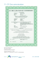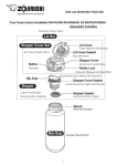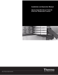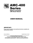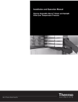
1
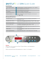
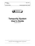
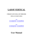
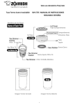
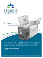
Shuttle™ ULT:25N -86˚C Portable Ultra-Low Temperature Freezer Operating Manual 09.11.2014 6000 Poston Rd Athens, Ohio 45701, USA t: 740.274.7900 / 855.274.7900 f: 740.274.7901 www.stirlingultracold.com T H I S PAG E I N T E N T I O N A L LY L E F T B L A N K 2 of 28 Operating Manual: ULT:25N 10326.3 | 09.11.2014 ULT:25N Quick Guide Initial Setup Seven-segment display A Numerical display – chamber temperature, S ## – setpoint ON B Press and hold I/O for two beeps OFF B Press and hold I/O for three beeps See Setpoint C Press Set T briefly, S ## displayed Return to Temp Display C Press Set T briefly, or wait eight seconds Change Setpoint D Press and hold Set T until Set T LED glows, S ## displayed, or then Advanced Functions Change to Preset Press and hold Set until Set T LED glows, S ## displayed, then Preset 1, 2 or 3 Postpone Over T Alarm When Over T light glows, press Preset 3 until time shows (1.0 h) (If Over T LED is not glowing, then Preset 3 acts as a Temp Preset) Return to Temp Display Wait eight seconds, press Preset 3 to return to temperature display See Error Code Again If Error LED is glowing then press Preset 2 briefly (If Error LED is not glowing, then Preset 2 acts as a Temp Preset) Lock Panel Press and hold Preset 1 AND 2 AND 3 until Locked LED turns on (five seconds) Unlock Panel Press and hold Preset 1 AND 2 AND 3 until Locked LED turns off (five seconds) Seven-segment display P ## – Preset Temp, ## h – alarm silence, E ## – Error code A B C D Notice: When unit is first turned on, red Over T light will be on until temperature is within 10º of setpoint. Panel cannot be locked until temperature is within 10º of setpoint. Operating Manual: ULT:25N 10326.3 | 09.11.2014 www.stirlingultracold.com 3 of 28 T H I S PAG E I N T E N T I O N A L LY L E F T B L A N K 4 of 28 Operating Manual: ULT:25N 10326.3 | 09.11.2014 ULT:25N -86˚C Portable Ultra-Low Temperature Freezer The Shuttle model ULT-25N (Ultra-Low Temperature, 25 liter volume) incorporates next generation free-piston Stirling engine technology. Free-piston Stirling engine technology differs from conventional compressor-based refrigeration in that it provides high efficiency, deep-temperature cooling in a lightweight package allowing true portable operation. Table of Contents: 1. SAFETY PRECAUTIONS��������������������������������������������������������������������� 6-7 1.1 Injury Prevention��������������������������������������������������������������������������������������������������������������� 6 1.2 Damage Prevention��������������������������������������������������������������������������������������������������������� 7 1.3 Transportation Care��������������������������������������������������������������������������������������������������������� 7 2. UNPACKING AND SET-UP����������������������������������������������������������������������������������������8-9 3. FEATURES OF THE ULT-25N FREEZER����������������������������������������� 10-13 3.1 Pictorial Tour, Freezer���������������������������������������������������������������������������������������������� 10-11 3.2 Pictorial Tour, Control Panel ���������������������������������������������������������������������������������������12 3.3 Power Cords���������������������������������������������������������������������������������������������������������������������13 3.4 Intended Uses �����������������������������������������������������������������������������������������������������������������13 4. OPERATION ������������������������������������������������������������������������������������� 14-17 4.1 How to Turn the Freezer On/Off�������������������������������������������������������������������������������14 4.2 Changing the Set Temperature�������������������������������������������������������������������������� 14-15 4.3 Using Preset Temperatures�����������������������������������������������������������������������������������������16 4.4 Over-Temperature Alarm���������������������������������������������������������������������������������������������16 4.5 Error Conditions �������������������������������������������������������������������������������������������������������������17 4.6 Locking the Control Panel�������������������������������������������������������������������������������������������17 4.7 How to Switch Between Power Supplies �������������������������������������������������������������17 5. ERROR CODES��������������������������������������������������������������������������������������� 18 6. MAINTENANCE������������������������������������������������������������������������������������� 18 6.1 Caring for Your Freezer Gasket�����������������������������������������������������������������������������������18 6.2 Air Intake Filter�����������������������������������������������������������������������������������������������������������������18 6.3 Storage�������������������������������������������������������������������������������������������������������������������������������18 6.4 Cleaning�����������������������������������������������������������������������������������������������������������������������������18 7. TROUBLESHOOTING ��������������������������������������������������������������������������� 19 8. CALIBRATION GUIDE��������������������������������������������������������������������� 20-21 9. SPECIFICATIONS����������������������������������������������������������������������������� 22-23 9.1 Freezer Specifications���������������������������������������������������������������������������������������������������22 9.2 Freezer Dimensions�������������������������������������������������������������������������������������������������������23 9.3 Pull-Down and Warm-Up Characteristics �������������������������������������������������������������23 10. WARRANTY ����������������������������������������������������������������������������������� 24-25 11. CE DOCUMENTATION ����������������������������������������������������������������������� 26 Operating Manual: ULT:25N 10326.3 | 09.11.2014 www.stirlingultracold.com 5 of 28 1. Safety Precautions To prevent personal injury, injury to others, or damage to property, read these safety precautions carefully before use. 1.1 – Injury Prevention • Do not cut, change or modify the power cable.* • When removing the plug, hold onto the plug and not the cord. • An ultra-low temperature freezer is qualitatively different than a home freezer. At -86ºC frostbite can occur instantly. • The user should establish and follow a protocol for safe ultra-low temperature operating procedures. This should include (but not limited to): — Never handle samples or freezer accessories with bare hands. — Do not use gloves which become brittle at ultra-low temperatures. — Nitrile and latex gloves are inadequate. • Permeable gloves are dangerous because ultra-low temperature materials can contact skin and cause damage. — Be especially careful that materials at ultra-low temperature are not spilled ontoskin or clothing. — Use only sample containers that have been approved or tested for ultra-low temperature use. — Some plastics shatter at ultra-low temperatures. Avoid splinter hazards. — Biological and chemical hazards are still hazardous at ultra-low temperature. Always wear proper protective equipment and follow appropriate isolation protocols. — Many types of labels will fall off and/or break at ultra-low temperature. Some types of ink which stick to glass and/or plastic at room temperature lose adhesion at ultra-low temperature. • In addition to the ultra-low temperature hazards above, there are also physical hazards to consider: — Be cautious when closing the lid to avoid a pinching hazard. — Be careful when loading the box with heavy items. — Always use the handles to carry the freezer. 6 of 28 Operating Manual: ULT:25N 10326.3 | 09.11.2014 1. Safety Precautions 1.2 – Damage Prevention • Do not disassemble, modify or repair. There are no user serviceable parts inside the freezer unit.* • Do not immerse in water or pour water on the unit.* • Do not put ice or liquid water directly in the freezer box, always use suitable containers. • Do not use glass containers when the contents might freeze and break. • Do not store flammable items such as gasoline, thinner or solvents in the freezer. The freezer is NOT rated as an explosion-proof freezer. • Do not use hard and/or sharp objects, such as knives, screwdrivers, etc. to remove any frost or ice which has accumulated on the inside of the freezer. The inside panels are heat exchangers and can be damaged. • Do not block the air intake or air discharge vents. • Do not drop, throw or abuse the freezer.* • Do not operate under extreme environmental conditions, such as in a car trunk, in very high humidity environments, in rain or other severe weather.* • Do not use solvents to clean the control panel or the outside or inside of the freezer. 1.3 – Transportation Care • Only ship via ground transportation to ensure proper unit function (especially important for domestic addresses). • Use only factory-provided packaging. If unavailable, contact Global Cooling for replacement packaging materials. • Do not place unit on sides or turn upside down. *Warning: Unauthorized modification to the cabinet, controls or free-piston Stirling engine is prohibited and will void all warranty provisions. Operating Manual: ULT:25N 10326.3 | 09.11.2014 www.stirlingultracold.com 7 of 28 2. Unpacking and Set-Up 1. Remove the freezer and all accessories from the box. Carefully inspect the freezer and all accessories for any shipping damage. 2. Check the packing list to verify that the shipment is complete. 3. Place the freezer on a level surface. 4. Make sure that the air inlets and outlets are not blocked. 5. Connect to a power source. The freezer can be used with either the AC Power Supply for lab, home or office use, or the DC Power Cord for mobile use. A. To use the AC Power Supply: i. During setup, identify the service power and plug configuration available and then locate the appropriate line cord for the service type you will be using. ii. If the appropriate line cord is not currently installed, simply unplug the line cord from the unit and then plug the appropriate line cord in its place. iii. Plug the other end of the line cord into the power source and then attempt to power on the Shuttle. B. To use the DC Power Cord in a motor vehicle: i. Make sure the freezer remains level. Exceeding an angle of 12 degrees may cause loss of cooling. ii. Plug the DC Power Cord into a 12V outlet that is rated at 20 amps. (NOTE: Not for use with 24 volt automotive systems.) (20 A DC REQUIREMENT: Consult your automotive specialist if your vehicle lacks 20 A rated 12V outlets.) iii. Plug the opposite end into the ULT-25N. Slide the male line cord adapter into the female connection port, lining up the two plastic bungs on the male adapter with the cutouts in the female port of the ULT-25N. Press the male adapter firmly into the connection port and turn clockwise until an audible “click” indicates full connection. 8 of 28 Operating Manual: ULT:25N 10326.3 | 09.11.2014 2. Unpacking and Set-up 6. Notes on operation in a vehicle. A. The ULT-25N will operate on battery power for a limited time before the battery is drained and the motor vehicle cannot be started. This time will vary from vehicle to vehicle but is generally only a few hours. B. The engine should be running to prevent accidental total discharge of the battery. C. The power to 12V outlets in some vehicles may be interrupted during engine starting. This will cause a sudden stop of the cooling unit which may produce a sound that is different than when turning off the ULT-25N by using the Off button. This is normal and will not damage the cooling engine. The cooling engine will restart automatically once power resumes. D. 20 A DC REQUIREMENT: Please note that 20 A DC service is required for proper functioning of the ULT-25N in a motor vehicle. Some vehicles may not be equipped with 20 A DC service. Consult your automotive specialist to verify the level of DC service installed in your vehicle. E. 7. Do not operate the ULT-25N in an unattended vehicle. This may lead to overheating if left in the sun and subsequent damage to stored contents. Disconnecting from power. A. Turn off the freezer (see page 14). i. The seven-segment display will show the word “OFF” while the Shuttle ULT-25N turns off. ii. Unplug the freezer after the word “OFF” disappears and the display goes dark. iii. If you unplug the freezer while it is on, you will hear a sudden noise when the free-piston Stirling engine shuts off. Power outages will also cause the same noise. This noise (sort of a “bonk”) is not indicative of damage. Operating Manual: ULT:25N 10326.3 | 09.11.2014 www.stirlingultracold.com 9 of 28 3. Features of the ULT-25N Freezer 3.1 – Pictorial Tour, Freezer The Stirling Ultracold Shuttle ULT-25N free-piston Stirling engine ultra-low temperature freezer has the following features: 1. A freezer chamber which is protected by two lids — Inner lid has a tight fitting foam lid. 2. Control Panel — Described in more detail on page 12. 3. Lid latch — For positive closure. 4. Access port — For thermocouple wires, etc. 5. Cleanable filter — Helps protect the heat rejection fins from dust. 6. AC Power Connection — Polarized to avoid error. 7. DC Power Connection 8. Temperature Probe Clip (optional) — For holding the temperature probe in place for calibration and monitoring 3 9. Remote Alarm Contacts (optional) 10. Key Lock — Locking lid for sample integrity. 1 8 11. Power Supply Fan 12. Vent 2 4 9 10 12 5 7 10 of 28 Operating Manual: ULT:25N 10326.3 | 09.11.2014 3. Features 1 Outer Lid: double gasket moisture seal. 4 Inner Lid: high-density, closed cell, rigid foam. 5 Slide-out Filter: easy to clean, protects heat rejection fins. Access Port: 1/4” (6.3 mm) standard– may be enlarged up to 1” (25.4 mm). 6 7 AC Power Connection. DC Power Connection. 8 11 9 Temperature Probe Clip (optional). Remote Alarm Contacts (optional). 6 Operating Manual: ULT:25N 10326.3 | 09.11.2014 www.stirlingultracold.com 11 of 28 3.2 – Pictorial Tour, Control Panel A. Seven-Segment display — Shows all numerical displays; default display is chamber temperature. B. On/Off button and LED — Turns freezer on and off and shows state. C. Set Temp button and Set Temp LED — This must be pressed to adjust the Set Temperature. D. / buttons — Used to adjust Setpoint Temperature (when the display shows S ##). E. Error LED — Indicates when there is an electrical, mechanical or similar error condition. F. Over Temp LED — Indicates when the chamber is over/under the setpoint. The audible beeper can be set to delay warning. G. Locked LED — Indicates when the control panel is locked. H. Temperature Preset buttons A G F C B D 12 of 28 E Operating Manual: H ULT:25N 10326.3 | 09.11.2014 3. Features 3.3 – Power Cords One power cord is supplied with each Shuttle, however a simple line cord change can allow for multiple power and receptacle types. To change the line cord, ensure the unit is turned off. Unplug the old line cord from the rear of the unit and plug the new line cord in its place. Make sure to use the cord and plug appropriate for your location. The options below are available: • Line Cords for North America. 120V, AC, 60Hz. NEMA 5-15P plug. Requires standard NEMA 5-15R receptacle. • Line Cords for Europe/International. 240V, AC, 50Hz. Standard two-pin plug. Requires two-pin receptacle. 3.4 – Intended Uses The Shuttle ULT-25N freezer provides ultra-low temperature storage for both medical and non-medical purposes. The Shuttle ULT-25N is registered with the FDA as a Class I medical device (Product Code JRM). The storage of blood or blood products intended for medical purposes is prohibited. Operating Manual: ULT:25N 10326.3 | 09.11.2014 www.stirlingultracold.com 13 of 28 4. Operation Important changes to the freezer settings require sustained button pushes. This helps prevent accidental changes to the settings during transportation. Some sequences require a three-second button press and hold while other sequences require a five-second button press and hold. For example, Turning the freezer ON requires a three-second press and hold (two beeps). Turning the freezer OFF requires a five-second press and hold (three beeps). The default display is the chamber temperature. Other displays such as Setpoint, Alarm Postpone, etc., are marked with a letter such as S (Setpoint), h (Alarm Postpone), etc. These secondary displays revert to the default display after approximately eight seconds of button inactivity. 4.1 – How to Turn the Freezer On/Off 4.1.1 – To Turn the Freezer On • Press and hold the I/O button for two beeps (~three seconds). • The freezer will display a greeting message, and then display the chamber temperature. 4.1.2 – To Turn the Freezer Off • Press and hold the I/O button for three beeps (~five seconds). • The freezer will display “OFF” for 10 seconds, and then go dark. 4.2 – Changing the Set Temperature 4.2.1 – To See the Current Set Temperature • Press the Set Temp button briefly. • The current set temperature will be displayed with the letter S ##. — After eight seconds of inactivity the display will revert to the current temperature. 4.2.2 – Change the Setpoint to a New Value • There two ways to change the Setpoint. — Manually adjusting the temperature using / — Using one of three adjustable Preset Buttons. . • Adjusting the Setpoint manually. — Because of the importance of the Setpoint Temperature, changing the Setpoint requires a “two-button procedure”. This means: Method A - either holding the Set Temp button while simultaneously pressing. / — OR Method B - holding down Set Temp until the Set Temp LED glows and then pressing / . (Methods A and B achieve the same effect. The user can use whichever method they prefer.) 14 of 28 Operating Manual: ULT:25N 10326.3 | 09.11.2014 4. Operation • To change the Setpoint by Method A — Press and hold the Set Temp button and then push the release the Set Temp button). / buttons (do not – The Setpoint temperature will appear with the prefix S in the seven-segment display. – When the / buttons are first pushed the Setpoint will change by 1ºC at first. – If the / buttons are held for five seconds the step size will increase/decrease by 5ºC. – If the / buttons are briefly released (less than a half second) while continuing to hold down the Set Temp button the increment/ decrement size will return to 1ºC. – Release all buttons once the desired Setpoint is achieved. The display will return to chamber temperature after about eight seconds. • To change the Setpoint by Method B — Press and hold the Set Temp button until the Set Temp LED glows. – The Setpoint temperature will appear with the letter S in the first seven-segment display. — The / buttons can be used to change the Setpoint. – When the / buttons are pushed the Setpoint will change by 1ºC at first. – If the / buttons are held for five seconds the step size will increase to 5ºC. – Briefly release (a half second) the / buttons while continuing to hold down the Set Temp button the increment/decrement size will return to 1ºC. – Release the / buttons once the desired Setpoint is achieved. — Press the Set Temp button briefly (less than one second) to turn off the Set Temp LED. The display will return to chamber temperature. Operating Manual: ULT:25N 10326.3 | 09.11.2014 www.stirlingultracold.com 15 of 28 4.3 – Using Preset Temperatures • The three buttons labeled 1, 2 and 3 can be used to quickly change the Setpoint to frequently used values. When shipped the Presets are set to -86ºC, -40ºC, and -20ºC. • To choose one of the preset temperatures: —Press and hold the Set Temp button until the Set Temp LED glows. —Push one of the Preset Temperature buttons briefly. —The new set temperature will be shown in the seven-segment display. —If this is the desired Set Temperature the user can either: – Briefly press the Set Temp button to turn off the Set Temp LED. — OR – Wait for approximately eight seconds when the freezer control panel will return to normal operation. 4.4 – Over-Temperature Alarm • If the freezer compartment temperature is 10ºC warmer or colder than the Setpoint for five seconds then it will go into temperature alarm mode. —The Over Temp light will go on (this is used for under temperature alarms as well). —The freezer will make a double beep every 10 seconds. —Situations which can affect the freezer’s ability to maintain a steady state or cooling rate include: – The lid is ajar – The air vents are blocked – Addition of a large relatively warm mass – Power supply problems – Mechanical and/or electrical problems 4.4.1 – How to Silence the Audible Temperature Alarm • The Over Temp light will always be lit when the cooler temperature is over or under the set temperature by more than 10ºC. 4.4.2 – To Postpone an Alarm • When the audible alarm is sounding it can be postponed. • Press the button beneath the Over Temp LED and the audible alarm will be turned off for 1 hour. 16 of 28 Operating Manual: ULT:25N 10326.3 | 09.11.2014 4. Operation 4.5 – Error Conditions • Certain conditions will cause an Error Code to be displayed on the seven-segment display, and the Error LED will be lit. —The error code will be of the form E ##, where ## is the error code. —The error code will be displayed for about five seconds and then the display will show the chamber temperature. The Error LED will stay on. —The error code can be recalled by briefly pressing the button under the Error LED. This will recall the error code for approximately 10 seconds. —If button 2 is pressed and held for five seconds (three beeps) this will clear both the seven-segment display and the Error LED. However, if the error condition persists the error cycle will start over again. 4.6 – Locking the Control Panel To Lock the Freezer Control Panel • Press and hold buttons 1, 2 and 3 until the freezer beeps three times. —The Locked indicator LED will light up. —The user cannot lock the control panel if there is an over temperature or error condition. To Unlock the Freezer Control Panel • Press and hold buttons 1, 2 and 3 until the freezer beeps three times. —The Locked indicator LED will then turn off. —The freezer will still indicate over-temperature alarms or error conditions while it is locked. The user has to unlock the control panel to address those alarms/conditions. 4.7 – How to Switch Between Power Supplies • There are several possible power sources for the ULT-25N. —GC provided DC power cable for power supply. —Automobile accessory plug (cigarette lighter). • When changing from one power supply to another the user should first stop the ULT-25N. —Turn OFF the ULT-25N (Press and hold the I/O button). —Wait for the free-piston Stirling engine to slow and stop (15 seconds). —Unplug the ULT-25N from the current power source and plug into the new, approved power source. Reference page 8, Part B for instructions on use of DC Power cable. —The ULT-25N can be restarted immediately, no wait time necessary. —Turn ON the ULT-25N by pressing and holding the I/O button. Operating Manual: ULT:25N 10326.3 | 09.11.2014 www.stirlingultracold.com 17 of 28 5. Error Codes These are displayed in the seven-segment display as E ##. 10 The free-piston Stirling engine is not maintaining a working temperature on the heat rejection fins. This could arise from blocked filters, blocked air passages, unusually hot ambient temperatures (for example >45ºC), or a fan failure. Check air passages and clear any blockages for good air circulation. Remove from hot environments (car interiors, etc.). 40 A component which monitors free-piston Stirling engine performance has failed. The free-piston Stirling engine cannot regulate itself. Please return for repair. 6. Maintenance 6.1 – Caring for Your Freezer Gasket The temperature differential between ambient and the ultra-low interior can attract moisture near the gasket. For best results always wipe away moisture during openings to prevent ice accumulation. Do not use sharp instruments to scrape ice from the surface. 6.2 – Air Intake Filter Clean accumulated dust and dirt on the air intake filter every month. Pull the filter cover to the left as shown. Please note that it cannot be completely removed. Gently clean the filter with a vacuum cleaner. If there are stubborn residues use a soft brush to work them loose. 6.3 – Storage 1. Turn off the power and allow the freezer to come to room temperature. 2. Dry the inside of the freezer compartment and clean any spills. 3. Disinfect with suitable sterilizing agent if the freezer has been used for biohazards. 6.4 – Cleaning The exterior surfaces of the ULT-25N can be cleaned as needed by using a soft cloth and mild detergent. Do not use solvent or harsh abrasive cleansers or pads. 18 of 28 Operating Manual: ULT:25N 10326.3 | 09.11.2014 5-7. Errors, Maintenance and Troubleshooting 7. Troubleshooting Problem Possible Cause Solution Freezer does not power on Power is not getting to the freezer from the Power Supply Check the connections to the power supply Assure that the wall plug is firmly seated Reseat the connections to the accessory plug Power is not getting to the freezer from the Auto Accessory Plug Assure that the Auto Accessory Plug has live power Remove any dirt or debris inside the accessory socket or on the plug Replace any blown automobile fuses Freezer does not achieve desired temperature Clean air filter screen Inadequate air circulation Remove air flow obstructions Assure that the wall plug is firmly seated Inadequate power Remove any dirt or debris inside the automotive accessory socket or on the plug Operate freezer only when automobile is running Remove freezer from direct sunlight, hot room, etc. Improper environment Freezer cools slowly 12V plug becomes unusually hot Operating Manual: Check that freezer is level. Tilts of more than 12 degrees in some directions will degrade performance. Overloading of freezer Remove some items from freezer Lid is not completely closed Check for ice buildup, remove if necessary, and properly close lid Lid is open and closed too often Minimize opening and closing of lid Inadequate air circulation Clean filter and unblock air vents Dirt or corrosion in the accessory socket Clean the socket ULT:25N 10326.3 | 09.11.2014 www.stirlingultracold.com 19 of 28 8. Calibration Guide Calibrating the RTD with an Independent Temperature Indicator The Shuttle RTD is factory calibrated to display both setpoint and operating temperature from a single internal RTD. In the event that you must re-calibrate the Shuttle to match the reading of an independent temperature recording device or stand-alone electronic thermometer, please follow this process. 1. Tools Required • Flashlight or work light. • Plastic screwdriver; do not use a metal screwdriver as this may short circuit the circuit board in the event of a slip. • Independent temperature thermometer with sufficient lead wire to pass through the 1/8" access port and affix with duct tape to the vertical liner channel. 2. Procedure 1. Place a thermocouple (1) inside the Shuttle cabinet. — Note: Display temperature is calibrated using a NIST traceable thermocouple located in the center of the cabinet (4.4” from back, 6.6” from left side, 6.7” from bottom). 2. Turn Shuttle on. 3. Set temperature to -80ºC. 4. Wait until the display reads -80ºC. — For best results wait an additional hour to ensure uniform cabinet temperature. 5. Connect a NIST traceable thermocouple reader (2) to the thermocouple located inside the cabinet. 6. Slide open filter door located on the side of the cabinet (3). 7. Using an extra-long screwdriver (4) (Recommended: Wiha #261 09) locate the potentiometer through filter opening (5). 8. Turn the adjustment screw until the Shuttle display temperature is the same as the hand-held instrument. ¼ Turn = 3 DEGREES 9. Turn the screw to change the temperature indicated on the display (clockwise for warmer and counter-clockwise for colder). 10. After making an adjustment, WAIT 15 SECONDS for the Shuttle indicated temperature to register the adjustment. Repeat adjustment if necessary. 11. Calibration complete. 20 of 28 Operating Manual: ULT:25N 10326.3 | 09.11.2014 8. Calibration Guide 1 2 Thermocouple HH-176 Handheld 4 3 Filter Door Adjustment Tool 5 Calibration Screw visible through filter Operating Manual: ULT:25N 10326.3 | 09.11.2014 www.stirlingultracold.com 21 of 28 9. Specifications 9.1 – Freezer Specifications Electric Power 120V or 240V, AC; 60Hz or 50Hz; or 12V DC from mobile source Maximum Power (Current) 280 watts (3.6 amps @120V, 1.8 amps @240V) Auto-Voltage Capability 88V to 264V, 50 or 60 Hz Electric Supply Rating 15 amp or greater grounded circuit Cooling Engine Humm™ helium charged free-piston Stirling engine with continuous modulation Refrigerant R-508B nonflammable CFC/HCFC-Free Temperature Range -86ºC to -20ºC @ 32ºC (90ºF) ambient, uniformity ± 0.75°C top to bottom, adjustable in 1°C increments Presets for -86°C (default), -40°C and -20°C Ambient Operating Temperature +5ºC to +35ºC (41ºF to 95ºF) Application Environment Non-corrosive, non-flammable, non-explosive Storage Volume 25 liters (0.9 cu.ft.) Interior Dimensions 13.1" L x 8.7" W x 13.4" D | (332 x 221 x 340 mm) Exterior Dimensions 27.3" L x 13.8" W x 18.1" D | (692.5 x 350 x 460 mm) Net Weight, Empty 46 lbs. (21 kg), nominal Insulation High performance vacuum insulated panels and polyurethane foam Noise Typical of laboratory equipment Control Sensor One RTD (PT100 Class B) Dry Contacts Optional Pull-Down 2.2 hours from ambient temperature to -80ºC setpoint Recovery 20 minutes from 1 minute lid opening to -80ºC setpoint Warm-Up Profile from -80ºC Setpoint 30 minutes to -60ºC 70 minutes to -40ºC 130 minutes to -20ºC Steady State Energy Use 2.8 kWh/day (average power 118 watts) Heat Dissipation (at -80ºC) 403 Btu/h (load to HVAC) 22 of 28 Operating Manual: ULT:25N 10326.3 | 09.11.2014 9. Specifications TOP TOP 9.2 – Freezer Dimensions TOP SIDE FRONT 13.8" (350 mm) 27.3" (692.5 mm) FRONT 13.1" (332 mm) FRONT .3" (8 mm) 18.1" (460 mm) 13.4" (340 mm) 8.7" (221 mm) SIDE 8.7" (220 mm) 13.5" (343 mm) PULL-DOWN AND WARM-UP 25ºC Ambient 9.3 – Pull-Down and Warm-Up Characteristics, º CHARACTERISTICS, 25 C AMBIENT 40 20 0 TEMPERATURE (º C) Air Temp, Empty Power OFF, Air Temp Middle Height, Pull-down to -86º C from Ambient -20 8 Liters of -86º C Ice, Middle Height -40 Air Temp, Empty -60 Power OFF, Ice Temp Middle Height, Steady State, Non-Cycling 8 Liters of -86º C Ice, Middle Height -80 Power Off -100 0 3 6 9 12 15 18 21 24 www.stirlingultracold.com 23 of 28 TIME (HOUR) Operating Manual: ULT:25N 10326.3 | 09.11.2014 141 Columbus Road Athens, Ohio 45701, USA t: 740.592.2655 f: 740.592.2695 www.stirlingultracold.com ©2011 Stirling Ultracold, Global Cooling, Inc . All Rights Reserved. HUMM™ technology is manufactured under one or more of the following patents: U.S. 6,901,845; 7,075,292; and other U.S. and International patents. Stirling Ultracold, Shuttle™ and HUMM™ are trademarks of Global Cooling, Inc. 10. Warranty The following Warranty applies to the Shuttle ULT-25N manufactured by Global Cooling, Inc. Due to the nature and size of the Shuttle ULT-25N, a product exchange via overnight or expedited shipping may be preferable to field-level service. In order to maintain maximum uptime and to optimize customer service, Global Cooling, Inc. reserves the right to exchange the ULT-25N with a serviceable new or previously-used replacement at its discretion. Limited Warranty, USA • The warranty period starts two weeks after the original date of shipment from Global Cooling, Inc. • The Shuttle ULT-25N is warranted for a period of ONE YEAR for materials and labor at our factory. • If a service issue arises, contact the Global Cooling, Inc. Service Department to register Warranty Service and initiate a resolution. • Advanced authorization for a service company to diagnose the problem must be approved by Global Cooling, Inc. • Global Cooling, Inc. will not be responsible for charges incurred for service calls made by a third party prior to authorization by Global Cooling, Inc. • Global Cooling, Inc. retains the right to replace any product in lieu of servicing it in the field. • Liability in all events is limited to the purchase value only. • Under no circumstances will Global Cooling, Inc. be responsible or held liable for consequential or incidental damages associated with loss of stored product in the event of an equipment failure. • Extended warranty programs are available. Contact Global Cooling, Inc. for a custom warranty solution. Limited Warranty, CANADA • The warranty period starts one month after the original date of shipment from Global Cooling, Inc. • The Stirling Ultracold Shuttle is warranted for a period of ONE YEAR for materials and labor at our factory. • If a service issue arises, contact the Global Cooling, Inc. Service Department to register Warranty Service and initiate a resolution. • Advanced authorization for a service company to diagnose the problem must be approved by Global Cooling, Inc. 24 of 28 Operating Manual: ULT:25N 10326.3 | 09.11.2014 10. Warranty • Global Cooling, Inc. will not be responsible for charges incurred for service calls made by a third party prior to authorization by Global Cooling, Inc. • Global Cooling, Inc. retains the right to replace any product in lieu of servicing it in the field. • Under no circumstances will Global Cooling, Inc. be responsible or held liable for consequential or incidental damages associated with loss of stored product in the event of an equipment failure. • Extended warranty programs are available. Contact Global Cooling, Inc. for a custom warranty solution. International Distributor Limited Warranty • The warranty period starts two months after the original date of shipment from Global Cooling, Inc. • The Shuttle ULT-25N is warranted for a period of ONE YEAR for materials only. • If a service issue arises, contact the International Distributor from where the ULT-25N was purchased. The Distributor will contact the Global Cooling, Inc. Service Department to register Warranty Service and initiate a resolution. • Global Cooling, Inc. must provide advanced authorization for the Distributor’s service company to diagnose the problem at the customer’s site. • Neither Global Cooling, Inc. nor the Distributor will be responsible for charges incurred for service calls made by a third party prior to authorization by the Distributor or Global Cooling, Inc. • Global Cooling, Inc. and the Distributor retain the right to replace any product in lieu of servicing it in the field. • The Distributor must provide Global Cooling with proper troubleshooting information. • Under no circumstances will Global Cooling, Inc. or the Distributor be responsible or held liable for consequential or incidental damages associated with loss of stored product in the event of an equipment failure. • Extended warranty programs are available. Contact your Distributor for a custom warranty solution. Operating Manual: ULT:25N 10326.3 | 09.11.2014 www.stirlingultracold.com 25 of 28 11. CE Documentation David M. Berchowitz Director of GCBV Authorized Representative Global Cooling BV (GCBV) Lage Dijk 22, Helmond, 5705 BZ, The Netherlands 26 of 28 Operating Manual: ULT:25N 10326.3 | 09.11.2014 11. CE Documentation Calibration Notes Operating Manual: ULT:25N 10326.3 | 09.11.2014 www.stirlingultracold.com 27 of 28 6000 Poston Road Athens, Ohio 45701, USA t: 740.274.7900 / 855.274.7900 f: 740.274.7901 www.stirlingultracold.com ©2014 Stirling Ultracold, Global Cooling, Inc . All Rights Reserved. HUMM™ technology is manufactured under U.S. and International patents. Stirling Ultracold, Shuttle™, HUMM™ and Swift™ are trademarks of Global Cooling, Inc. Specifications subject to change without notice. Refer to www.stirlingultracold.com for the latest specifications. Operating Manual: ©2014 Stirling Ultracold OW10326.3 09.11 ULT:25N 10326.3 | 09.11.2014 www.stirlingultracold.com 28 of 28