1
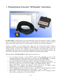
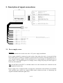
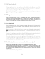
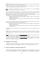
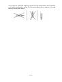
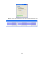
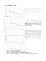
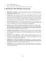
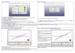
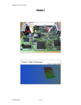
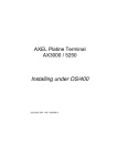
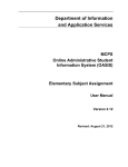
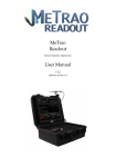
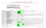
Timing Advance Processor
EG DYNAMIC
user manual
ver. 1.1.0 dated 2012-10-01
This instruction can be also downloaded from:
http://www.europegas.pl/en/Technical-Support/Service-Manuals
Latest software version and example movies of its usage can be downloaded from:
http://www.europegas.pl/en/Technical-Support/Software
Table of content
1. Timing Advance Processor “EG Dynamic” description...................................................................3
2. Description of signal connections....................................................................................................4
2.1. Power supply source.................................................................................................................4
2.2. MAP signal (optional)...............................................................................................................5
2.3. TPS signal.................................................................................................................................5
2.4. Activation signal.......................................................................................................................5
2.5. Crankshaft position sensor and camshaft position sensor signals............................................5
2.6. Diagnostic interface plug..........................................................................................................6
2.7. Proper installation of TAP EG Dynamic ECU..........................................................................6
3. Software description.........................................................................................................................8
3.1. Right panel – actual value of system parameters:.....................................................................8
3.2. Left panel – Settings bookmark................................................................................................9
3.3. Middle panel – Maps..............................................................................................................11
4. EG Dynamic TAP Calibration step-by-step....................................................................................12
Hint: Click with Your left mouse button on any of above chapters to go to its page.
2/12
1. Timing Advance Processor “EG Dynamic” description.
EG DYNAMIC Timing advance processor dynamically changes the moment of engine's ignition
while it is running on LPG/CNG fuel to improve combustion process efficiency. This way vehicle's
engine works more dynamically. Power losses during acceleration are practically eliminated.
Advance of ignition is very important when engine runs on CNG because CNG-air mixture
combustion time is much longer comparing to combustion time of petrol-air mixture. Usage of
Timing Advance Processor also eliminates risk of backfiring and significantly reduces gas
consumption. We can say that it is temporarily adapting the original vehicle's ignition system to use
LPG/CNG so the difference between driving on both fuel is practically imperceptible .
Main advantages of EG DYNAMIC Timing Advance Processor are:
•
•
•
•
•
•
It is no longer necessary to keep different TAP models depending on type of the
crankshaft/camshaft position signal type in particular car. EG DYNAMIC is scanning,
learning and supporting all inductive and digital crankshaft and camshaft signals.
Very easy calibration and configuration process with usage of multipliers user interface.
Possibility of dynamic and smooth advancing or delaying of ignition angle up to +-30
degrees, depending on the current values of TPS position, RPM and MAP signals.
Single TAP device supports one inductive sensor and up to two digital sensors
simultaneously. It is possible to connect them in any configuration.
Flexible adjustment of TAP activation moment . Advancing of ignition depends on actual
values of RPM and TPS signal and can be activated by “+” or by “-” signal.
Deactivation of TAP and restoring the original RPM signal in case of emergency can be
done easily by pulling out the fuse from fuse holder.
3/12
2. Description of signal connections
2.1. Power supply source
Attention:
Device is destined to be used in cars with +12V power supply installation.
Power supply should be connected to such a place from where the device is powered all the
time while engine is running. It should be present from the moment of turning ignition key in
ACC position until the engine will be switched off. It is unacceptable to connect this line to
places where +12V might dissapear: for example, where voltage may drop out while engine is
in the cut-off conditions.
Hint: In OSCAR-N SAS ECU we should connect it to the red-white wire connected to the
+12V ignition from the key.
Power supply wire is equipped with 1A circuit fuse, which after removal allows us to disable
TAP operation and restore the original RPM signal without necessity of shortening the
original camshaft/crankshaft signal wires.
4/12
2.2. MAP signal (optional)
Voltage signal taken from the signal wire of Manifold Absolute Pressure sensor. This
connection enables to measure the vacuum signal in the intake manifold so it is possible to
make corrections of ignition point angle depending on engine load.
Hint: In OSCAR-N SAS ECU we should connect it to the blue wire which goes to mapsensor
[pin no. 3 in 4-pole AMP mapsensor plug].
2.3. TPS signal
Signal of Throttle position sensor or acceleration pedal sensor. Connecting that signal is
required for proper calibration and detection of idle and cut-off conditions. TPS signal wire is
the one on which voltage (regarding the ground ) changes its value fluently (eg. from 0 to 5V)
when we are pressing on the accelerator pedal when vehicle's ignition key is on.
2.4. Activation signal
Signal which indicates when vehicle is running on gas and when on petrol. It is being used for
activation of TAP to start advancing the original RPM signal when all cylinders has been
switched to gas fuel.
Hint. In case of use of OSCAR-N SAS system the best way of taking the activation signal is
connecting to pink wire also used for disconnection of petrol fuel pump when system is on
gas.
Negative (“-”) signal appears on pink wire when OSCAR-N system is completely switched to
gas and disappears in the moment when the system is switched back to petrol.
We can also take positive (“+”) activation signal from +12V solenoid valve wire. In such case
we should set proper type of gas activation signal (by “+”) in the EG Dynamic software. Gas
controller should also be configured in such way to eliminate delays between moment of
activating solenoid valves and changeover to gas.
2.5. Crankshaft position sensor and camshaft position sensor signals
Main and most important signal to connect is the crankshaft position sensor signal.
Camshaft position sensor signal don't have to be connected if it is not necessary to do so. This
kind of necessity might happen when the original ECM of the car is report errors related with
not synchronizing the camshaft position signal while advancing the signal from crankshaft
position sensor.
At first we should identify the type of sensor.
5/12
Inductive sensor -usually it has pins which goes to two lines covered by a screen. Resistance
measured between these two lines is around 1000 Ohm.
If there are three pins, two of them are connected to signal lines and third one is connected
with screen which is the ground signal of vehicle's ECU.
Hint if possible we should find the place to cut into signal wires at where additional
cover/screen insulation of signal wires is not present.
First we should identify two signal wires, cut them and make serial connection by connecting
proper pairs of wires from TAP device. There are four wires used to cut into vehicle's
inductive signal wires: yellow and white -channel A, green and brown -channel B.
We should start with cutting only one signal wire at a time (let's name it 'signal wire A') and
connect first pair of inductive signal wires from TAP device:
• yellow wire -should be connected with vehicle's inductive signal wire A input going
from the inductive sensor
• white wire -should be connected with vehicle's inductive signal wire A output going
to the petrol ECU
Then we proceed with cutting second signal wire (let's name it 'signal wire B') and connect
remaining pair of inductive signal wires from TAP device:
• green wire -should be connected with vehicle's inductive signal wire B input going
from the inductive sensor
• brown wire -should be connected with vehicle's inductive signal wire B output going
to the petrol ECU
Attention: If above connections will be made improperly we may be be unable to start the
vehicle.
Digital sensor. -Usually that kind of sensor have three lines signal, ground, power supply:
+5V or +12V signal. We should cut only the signal wire and connect it serial to digital channel
pair of wires.
Hint: The original wire of signal input from digital sensor should be always connected to the
color wire with black stripe (violet- black or yellow-black color).
The adequate color wire without stripe should always be connected to that part of original
vehicle's sensor signal wire which goes to the petrol ECU (violet or yellow color). Otherwise
it might cause problem with engine work.
2.6. Diagnostic interface plug
Diagnostic interface wire plug should be connected to EG Dynamic interface. It is possible to
establish connection only if the TAP device is powered by +12V (the ignition key is on).
2.7. Proper installation of TAP EG Dynamic ECU
During the installation of TAP EG Dynamic ECU is suggested for the wire
set to point downwards. It is also suggested that it should be placed in
6/12
such a way to avoid the negative impact of high temperature and humidity.
It is highly prohibited to spray ECU box with water jets or expose it to long
lasting contact with water.
7/12
3. Software description
3.1. Right panel – actual value of system parameters:
•
•
•
•
•
•
•
•
•
•
Shifting – this value is informing if the impulses are being advanced or delayed (ON) or not
(OFF) at the present moment.
Gas – this value is signaling on what fuel the car the car is actually running: on gas (ON) or
petrol (OFF).
Angle [`] - angle value (in degrees) by which the current revolutions signal is being shifted.
RPM – rotary engine speed value.
TPS [%]– position of throttle position percentage (accelerator pedal).
MAP [kPa] – actual value of pressure in the intake manifold (engine load).
Inductive [Hz] - the current number of pulses per second for a signal from the inductive
sensor.
Digital 1 [Hz] - The current number of pulses per second for a digital sensor signal no.
Digital 2 [Hz] - The current number of pulses per second for a digital sensor signal no.
Power supply [V]- power supply value. This value shouldn't be lower than 9V and not
higher than 15V.
If any parameter is marked by purple colour, it means that its value is out of allowed working range
which determines when signal shifting can be done. Eg. the car is not in gas mode or the TPS signal
is below minimum value which has been programmed to start shifting.
.
8/12
If any parameter is marked by red colour, it means that its value is beyond the border value. It
prevents proper operation of TAP device. It might also mean that device does not recognize the
shape of sensor signal wave. In such case it is necessary to physically check the signal connection
and do another signal scanning from the software.
3.2. Left panel – Settings bookmark
•
•
•
•
•
•
TPS Calibration - calibration of the minimum and maximum TPS input voltages for fully
depressed and pressed accelerator pedal.
Enabling configuration - conditions that must be fulfilled so in the automatic mode the
signal pulses shifting can be done.
Pressure sensor - selects the type MAP pressure sensor connected (in OSCAR-N SAS it's
ABS400kPa).
Signaling work on the gas - the choice of polarization of signal which enables shifting the
signal pulses: If the TAP activation wire connection has been done to positive signal wire
(like +12V solenoid valve wire) we need to choose “plus”. If we've connected it to fuel
pump disconnection signal (pink wire from OSCAR-N SAS which gives “ground” signal)
we need to choose “minus”.
TPS acceleration correction - the choice of TPS signal changes sensitivity. It's helpful in
cases at which original ignition signal angle temporary increases significantly when
accelerating. This allows to temporary increase the angle of signal shifting by extra velue for
the rapid accelerations to compensate this signal change. It works only if RPM value is less
than 1500 RPM.
Attention: It is not reccomended to increase value of that parameter if it is not necessary.
Inductive sensor, digital sensor 1, digital sensor 2
◦ Connections - selection of type of shaft where signal has been connected.
◦ Impulses per 1 revolution: number of pulses per revolution detected during a scan run
(control value)
◦ Scan – starts automatic scanning the sensor signal wave. Should be carried out under
stable conditions when the engine is running on idle. It is necessary to provide the actual
value of engine rotary speed before starting scanning.
In case that we've already scanned the wave of crankshaft sensor signal, and we need to
get the shape of camshaft position signal wave we can select that option to allow the
signal to be read from that channel.
Attention: It is very important to always start scanning from the crankshaft sensor
signal, and proceed to scanning of the camshaft sensors signals (if they have been
connected)
9/12
◦ Preview - feature which enable us to check the shape of scanned sensor signal wave.
10/12
3.3. Middle panel – Maps
Map of the angle shifting regarding engine
rotary speed.
Point of the violet line indicates the current
signal pulses shifting offset (in degrees).
It is recommended to set a lower angle value
at higher rotary speeds.
Multiplier Correction (eg. 1.0 is 100%, 0.6 is
60% of original shifting offset) of the angle
regarding the engine manifold absolute
pressure (load).
For heavy loads is recommended to set the
adjustment below 1.0 to do not increase the
engine knock value.
Multiplier Correction (eg. 1.0 is 100%, 0.6 is
60% of original shifting offset) of the angle
regarding
the
TPS
signal
value.
For idle conditions signal pulses shifting
should be disabed , because it can lead to
engines RPM waving in some type of
vehicles. We can do it by lowering the
multiplier line on the map or in the Settings
panel.
Allowed shortcuts and controls for map modification:
• Left mouse button - move the points in the X and Y axis.
• Right mouse button - move only points in Y axis.
• Double click by left mouse button -add or remove point.
• Arrow left, arrow right - selection of point.
• Shift + arrow left, Shift + arrow right - selection of a group of points.
• Ctrl + A – selection of all the points.
• Arrow up, Arrow down - moving points in the Y-axis.
• Home, End - moving points in the Y-axis with a higher speed
• Ctrl + arrow up, Ctrl + down, Ctrl + left, Ctrl + right -moves points in the X and Y
11/12
•
•
•
Insert - adds another point
Delete - removes the selected point
Page Up, Page Down - moves the whole multiplier line in the Y-axis
4. EG Dynamic TAP Calibration step-by-step.
1. Establishing a connection – Turn on the ignition key to give +12V to the TAP device.
Please select the right the serial port number from "Port" menu to establish a connection
with diagnostic interface device.
2. Calibrate TPS - while the engine is off, please make sure that ignition from the key is still
on and TAP device is being powered by +12V. In "TPS calibration", press "Set" button
when the accelerator is fully depressed to remember that value as “Bottom TPS Threshold”.
Then fully press the pedal all the way down and press "Set" button to store the maximum
TPS voltage value as “Top TPS Threshold”. Check if changing the position of the
acceleration pedal causes changing the current value of the TPS smoothly from 0 to 100%
3. Selection of pressure sensor. -after selecting the appropriate sensor type when engine is off,
and +12V from igniton on, the value of this parameter to indicate the MAP should be about
100 kPa. The default pressure sensor for OSCAR-N SAS is ABS400kPa.
4. Selection of the activation of signal which indicates that vehicle is workng on gas depending on where you connect the activation signal of TAP activation wire. If it has been
connected to positive signal wire (eg. +12V solenoid valve wire) we need to choose “plus”.
If we've connected it to fuel pump disconnection signal (eg. pink wire from OSCAR-N SAS
which gives “ground” signal) we need to choose “minus”.
5. Crankshaft sensor configuration - depending on the type of sensor and connection made to
it (inductive or digital) we need to select proper type of that sensor in “Settings” panel.
Then we should run a scan when the car is having working temperature and it is running on
idle conditions..
6. Camshaft sensors configuration – camshaft sensors should be connected only when
necessary (eg. when while shifting only the pulses from the crankshaft sensor, there is a
check-engine associated with the camshaft sensor). The process of configuration is the same
as in the case the crankshaft sensor configuration.
7. Configuration of conditions of shifting the sensors pulses -In "Enabling configuration"
panel we have to select the desired scopes of the TPS position, rotary speed, and select the
“Shifting mode” to “automatic”. Mode “Always”which is permanently forcing TAP to shitf
the signal pulses should be used onlyfor diagnostic purposes.
8. Setting the map – We can leave default maps of sensor signal shifting or we can modify it
according our requirements depending on the rotary speed, and the correction of the position
of the TPS and MAP (load).
12/12