1
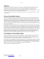
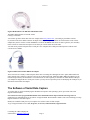
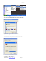
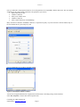
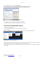
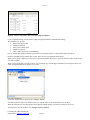
VRX Company
Application Note:
Serial Data Capture.
Inc.
Version 2.1
NOTICES
This document is copyright by VRX Company Inc. Copyright law prohibits reproduction of any part of this document in any
form without express written permission.
Notice: The contents of this document are subject to change without notice. At VRX Company Inc., we have made every
effort to ensure the accuracy of the contents of this document. However, we reserve the right to change this document for
improvement and to correct errors without notice. If you find errors, please bring them to our attention. Our contact
information is located at the bottom of this page.
Table of Contents
Abbreviations and Phrases............................................................................................................................................................2
Theory of Serial Data Capture.......................................................................................................................................................3
The Hardware of Serial Data Capture...........................................................................................................................................3
The Software of Serial Data Capture.............................................................................................................................................4
The Process of Serial Data Capture...............................................................................................................................................7
Sending the Captured Data............................................................................................................................................................9
Still having questions?...................................................................................................................................................................9
Abbreviations and Phrases
ASCII
Standardized codes for characters used by most computers. For example the
character “A” is code decimal 65.
BPS or bps
Bits Per Second
NULL MODEM CABLE
A cable that adapts two data sources (computers) for serial communication.
Generally female to female with crossed data and hand shaking connections.
OSD
On Screen Display
PC
Personal Computer
Table 1 Abbreviations used in this manual
Contacting the VRX Company Inc.
Send email to: [email protected].
Page 2
Version 2.1
Objective
The objective of this document is to enable someone with a novice understanding of the Personal Computer to capture a
serial data stream. The captured stream is saved as a text file and can easily be emailed to a programmer to enable
customization of the operation of the VRX Company Inc Text Inserters. Although there are standards for serial
communications there is still plenty of room for unique and unanticipated applications of serial communication. A captured
stream of data is often the best and fastest way to understand the application.
Capturing the data from a serial data source is not difficult once you have the idea. This document will help you overcome
the common hurtles.
Theory of Serial Data Capture
The serial communication of data is one of the oldest ideas of electronic computers. Serial communication was achieved
using an acoustic modulation so that data could be transmitted over telephone lines. The hardware that makes the acoustic
modulation was called a modulator/demodulator which was quickly shortened to MODEM. A standard connector and cable
was developed to connect computers [the data source] to MODEMS [the data sink.] It is standard for the data source to have
male pins on the connector. The data sink has female pins on the connector. The cable between them is female to male. Data
sinks such as modems, printers and displays typically have female connectors. This was all well and fine when computers
were room or even building sized machines. The only way to connect such computers together was through a modem on each
end of an analog telephone line.
When computers became small and portable the desire occurred to connect them directly with out the telephone line and the
two MODEMs on each end. Each computer has a connector appropriate for a data source with male pins. The standard male
to female cable will not mechanically work. There is an electrical problem too. Each computer has pins used to send data and
pins which receives data. You cannot connect the send pin of one computer to the send pin of the other. A special cable is
available to cross the connections. Such a cable crosses the send data circuit of one computer to the receive data circuit of the
other. This cross connected cable is referred to as a NULL MODEM cable. Not only are the data paths crossed, so are the
additional signal lines used by the computers to verify connection to one another. These verification lines are called
handshaking. The original serial MODEM connections were through a 25 pin connector called a DB25. The advent of the
IBM AT computer introduced a simplified serial MODEM connection using a 9 pin connector called a DB9.
The Hardware of Serial Data Capture
To capture serial data from a source such as a computer, GPS data port or cash register data port you will need a personal
computer with a serial port and a correct cable or combination of cables and adapters. Serial data cables come several
versions. Some have 25 pin connectors on each end, some have 9 pin connectors on each end and some applications mix 9
pin and 25 pin connectors. You will also need some software covered in the following section.
The ideal cable is the NULL MODEM cable and it has female ends and is cross connected. With an ohm meter or continuity
checker a simple test will tell you if you have a NULL MODEM cable or not. For any cable type, 25 pin or 9 pin, if pin 2 of
one end is connected to pin three of the other end your cable is a NULL MODEM. If pin 2 of one end is connected to pin
three of the other end your cable is a NULL MODEM. If pin 2 of one end is connected to pin 2 of the other end your cable is
straight across. We suggest you label your cables as NULL or straight to prevent confusion.
Radio Shack sells a NULL MODEM cable pictured below.
Contacting the VRX Company Inc.
Send email to: [email protected].
Page 3
Version 2.1
Figure 1Radio Shack 6-Ft. DB9 F/F Null Modem Cable.
The Radio Shack numbers are: Model: 03044
Catalog #: 55010600
You can also get these cables mail order. For example from www.jameco.com you would get part number 181403.
If your data source has a DB25 connector an adapter from 25 pin to 9 pin is available. Be careful because some of these
adapters may also be wired as a NULL MODEM. Two NULL MODEMS will cancel out. Once again use your continuity
meter to check for connection from pin 2 on one end to pin 2 on the other end of the cable.
You will need a personal computer with a serial port. New computers have USB ports and inexpensive USB to serial
converters are available.
Figure 2 Radio Shack USB to DB9 Serial Adapter
These converters are actually a small computer in the cable converting the USB signal to serial. Again, Radio Shack and
other computer stores sell these converters and you can get them mail order. Install the USB to DB9 serial adapter per the
instructions provided by the manufacturer. You will need to use some ingenuity to determine to which number COM port
your adapter has mapped the new serial port. Caution: you may need to repeat the process of identifying the COM port if you
disconnect and reconnect the adapter.
The Software of Serial Data Capture
To capture data you need a terminal program. Windows® computers with operating systems, up to XP® come with
HyperTerminal included.
For Vista® a freeware program RealTerminal can be downloaded from: http://realterm.sourceforge.net/This
application note will illustrate the set up and use of HyperTerminal. Real terminal is similar. This section will help you setup
HyperTerminal for serial data capture.
Identify the available COM port on your computer. We assume COM1 for this example.
To get to HyperTerminal ™ use: start, Programs, Accessories, Communications, HyperTerminal.
Contacting the VRX Company Inc.
Send email to: [email protected].
Page 4
Version 2.1
Figure 3 Starting HyperTerminal™
First setup HyperTerminal ™ for a new connection. Call it Data.
Figure 4 New HyperTerminal ™ connection.
Set for the desired COM port. In this example we use COM1.
Contacting the VRX Company Inc.
Send email to: [email protected].
Page 5
Version 2.1
Next you will need to setup HyperTerminal ™ for several parameters for compatibility with the data source. The user manual
should tell you the values of these parameters. The parameters you need are:
• BPS (or Bits Per Second)
• Number of data bits.
• Parity, Even, Odd or None
• Number of stop bits.
• Flow Control (also known as handshaking)
Many serial devices default to 9600 BPS, 8 data bits, 1 stop bit and no parity. If you do not know or can not find the setup in
the user manual this is a good setup to try first.
Now you should have an open HyperTerminal window.
Figure 5 Open HyperTerminal™ window.
You need to set HyperTerminal™ not to append line feed characters to incoming carriage return characters.
Select File, Properties or mouse click on the Properties icon.
Contacting the VRX Company Inc.
Send email to: [email protected].
Page 6
Version 2.1
In the properties dialog box, select the ASCII SETUP icon.
In the ASCII Setup dialog box, de-select the Append line feeds to incoming line ends button.
Select OK and OK to save the changes and return to the main HyperTerminal™ window.
Figure 6 De-select Append line feeds to incoming line ends
You should now be ready to connect everything and try to capture data.
From HyperTerminal select: File, Save to keep the changes you just made.
The Process of Serial Data Capture
Turn off power to all components.
Connect the NULL MODEM cable between the data source and the capture PC.
Turn on the computer.
Open (run) the Data HyperTerminal™. It will be in the sub-folder near where you found HyperTerminal™.
Figure 7 Run your new terminal “Data.ht”.
Watch the HyperTerminal™ screen while you apply power to and otherwise turn on the data source. Using the user manual
for the data source, get the data source operating in the mode where it is putting out data.
ASCII data on the HyperTerminal™ screen will be quite readable. However, some devices may output binary data which will
not be readable.
Contacting the VRX Company Inc.
Send email to: [email protected].
Page 7
Version 2.1
Figure 8 ASCII receipt printer data received by HyperTerminal™.
If you are getting nothing, you may need to change the HyperTerminal™ communication settings.
The parameters you need are:
• BPS (or Bits Per Second)
• Number of data bits.
• Parity, Even, Odd or None
• Number of stop bits.
• Flow Control (also known as handshaking)
First try another BPS, 4800 and 2400 are good choices for slow data devices. Try them all first before moving on.
Return to 9600 BPS and try enabling flow control. There are two types, hardware and software.
When you are getting valid data you may want to experiment with the data source to get it into all of the modes of data output
you want to capture.
When you are getting data you want to capture, you can simply copy from the HyperTerminal™ screen and paste into a text
editor, or HyperTerminal™ can capture to a text file.
To start the capture from the menu bar use: Transfer, Capture.
You will be asked to brows to the location where you want the file to be saved and chose a save file name.
When all of the data you want has appeared on the HyperTerminal window, close the file causing it to be saved.
To close the file from the menu bar use: Transfer, Capture, and Stop.
Contacting the VRX Company Inc.
Send email to: [email protected].
Page 8
Version 2.1
Sending the Captured Data
This catpured data can be useful to programmers developing products to interface with a serial data source such as computer
programs, GPS receivers, cash registers.
Embedded in the body or attached to an email a raw text file can become corrupted. To protect data integrity, before you
email this file compress it with a program such as Winzip® or ZipGenus®.
Attach the compressed file to the email in the normal way.
Still having questions?
If you are having compatibility trouble with the POS system and your Text Inserter, please look for updated information on
our web site at www.vrxinc.com
Contact the VRX Company Inc at [email protected] or by calling 1-866-543-8398 9-5 Eastern Time.
Snail Mail at: VRX Company Inc. PO Box 4663, Maryville, TN 37802-4663
Contacting the VRX Company Inc.
Send email to: [email protected].
Page 9