1
Comfile Technology
www.comfiletech.com
Overview
FA-DUINO-12RA User's Manual
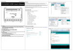
Select the Arduino Mega 2560 option from the Tools-->Board menu.
The FA-DUINO is an Arduino-based industrial controller. It has features similar to those
found in other Arduino products and can be programmed with the Arduino IDE.
Other Arduino products are not very well suited for fields such as factory automation. The
FA-DUINO has been designed to handle signals of higher voltage and current, and remove
the burden of external circuit design and fabrication from the user.
The FA-DUINO requires only simple connections to its terminal blocks and headers without
the need for external peripherals.
The FA-DUINO-12RA
The FA-DUINO-12RA has a built-in Mega2560 MCU
•
Program memory: 256KB
•
SRAM: 8KB
•
EEPROM: 4KB
•
Clock Speed: 16MHz
•
8 - 24VDC Inputs (pins 4~11)
•
4 – 10A Relay Outputs (pins 22~25)
•
1 - RS-232C Communication Port
•
4 – 0~10V Analog Inputs
•
4 – 0~20mA Analog Inputs
•
10-bit ADC (0~1023)
•
Powered by 24VDC
•
Operating Temperature: 0 ~ 60℃
•
Operating Humidity: 35 ~ 85% RH
Select the PC COM port that the FA-DUINO is connected to from the Tools-->Serial Port
menu. You can find the COM port number in Windows Device Manager.
Programming the FA-DUINO
The FA-DUINO can be programmed using the Arduino IDE available from http://arduino.cc
Write your program, and click the "Upload" icon to compile the program and upload to the
FA-DUINO.
Warning
1. For instruments with risk to life or property (e.g. nuclear power control, medical equipment,
vehicles, railways, aviation, combustion equipment, recreation equipment, safety devices, etc.),
always employ adequate fail-safe mechanisms.
- Risk of fire, personal injury, and/or property damage.
2. Always mount to a panel.
3. Do not attempt to repair, inspect, or wire while power is applied.
4. Do not attempt to alter or repair. Refer to a qualified technician.
5. Confirm all electrical connections
Caution
1. Do not use outdoors.
2. Always use the product within its specifications and ratings.
- Risk of fire and shortening of product’s life.
3. Do not exceed ratings of relay switching contacts.
4. Does not use in environments with flammable or explosive materials, moisture, direct sunlight,
radiation, vibration and/or shock.
5. Keep product free of dust and debris.
6. Make connections correctly and confirm polarity by measuring at the appropriate terminals.
IO Map
Direction
Pins
Input Voltage
Description
Input
4~11
0 or 24VDC (20~28V
is logic high)
24V = Logic High
0V = Logic Low
Output
22~25
10A Relay Outputs
Logic High = On
Logic Low = Off
Analog Input
0~7
0~3 – 0~20mA
4~7 - 0~10V
VA = analogRead(A0) // Read channel 0
VA = analogRead(A4) // Read channel 4
Example:
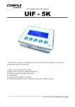
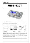
Physical Connections
Digital IO Connections
Mounting feet
Screw terminal block
for input
DC 24VDC power input
Led display
int val = 0;
int AD_val = 0;
// Digital input variable
// Read ADC value
pinMode(22, OUTPUT);
// Set pin 22 to output
val = digitalRead(4);
// Read from digital input 4
digitalWrite(22, val);
// Set digital output to same value as digital input
AD_val = analogRead(A0); // Read ADC channel 0
Screw terminal block
for output
Status LED
The FA-DUINO has a programmable status LED on pin 13 for providing visual indication to the
operator.
Example:
digitalWrite(13, HIGH);
delay(1000);
digitalWrite(13, LOW);
delay(1000);
//
//
//
//
Turn status
Delay for 1
Turn status
Delay for 1
LED on
second
LED off
second
Din Rail Mounting holder
Mounting feet
Connecting the Upload Cable
Upload
port
RS232C channel1
port
0~20mA Analog input
port
0~10VDC Analog
input port
Analog Input Connections
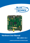
Using Proximity Sensors
DC 3-Wire Model (NPN type)
Proximity sensors can be used to detect the existence, movement, and displacement of
objects without any physical contact with the object. They are used quite often in the field of
automation.
Sensor output connected in reverse
Digital I/O Specifications
Input Specifications
Number of Inputs
8
Input Voltage Range
20VDC ~ 28VDC
Recommended Operating Voltage
24VDC
On/Off Switching Speed
10ms (Ladder Scan Time is 10ms)
Input Impedance
2.2kΩ @ 24VDC (Do not connect)
Output Relay Specifications
Number of Outputs
4
Input Voltage Range
5 ~ 30VDC / 4 ~ 264VAC
Recommended Operating Voltage
6 ~ 27VDC / 6 ~ 240VAC
On/Off frequency
10Hz (10 times per second)
DC 2-Wire Model
Maximum Current
10A per relay
Sensor output connected in reverse
Minimum Current
100mA per relay
Analog I/O Specifications
Analog Current Input (0 ~ 3) Specification
Resolution and Error
10-bit, +/- 2%
Input Current Range
0mA ~ 22mA
Recommended Operating Current
4mA ~ 20mA
Type
Non-isolated, Built-in LPF
Analog Voltage Input (4 ~ 7) Specifications
Resolution and Error
10-bit, +/- 2%
Input Voltage Range
-0.5VDC ~ 10.5VDC
Don't connect series resistance
DC 3-Wire Model (PNP type)
Operating Voltage
0VDC ~ 10VDC
Sensor output connected in reverse
Type
Non-isolated, Built-in LPF
Communication Specifications
Communication Port Specifications
Type
RS-232 (+/- 10VDC)
Flow Control
No RTS Flow Control
Maximum Baud Rate
115200
Maximum Distance
2 meters
Simple Examples
Example 1 – Flashing the Status LED
const int StatusLED = 13;
void setup()
{
pinMode(StatusLED, OUTPUT);
}
void loop()
{
digitalWrite(StatusLED, HIGH);
delay(1000);
digitalWrite(StatusLED, LOW);
delay(1000);
}
Example 4 – Analog Input with the Serial Monitor
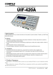
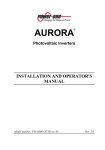
Interfacing with the UIF-5K
int ADI_Value0;
int ADV_Value4;
The UIF-5K is a 5-key character LCD panel that can be used in conjunction with the FADUINO to add a simple user interface.
void setup()
{
Serial.begin(9600);
}
void loop()
{
ADI_Value0 = analogRead(A0);
delay(100);
ADV_Value4 = analogRead(A4);
delay(100);
Serial.print(" CH 0 = ");
Serial.print(ADI_Value0);
Serial.print("\n" );
Example 2 – Toggling a Relay
const int Relay22 = 22;
void setup()
{
pinMode(Relay22, OUTPUT);
}
Front View
Serial.print(" CH 4 = ");
Serial.print(ADV_Value4);
Serial.print("\n\n" );
Description
delay(200);
}
void loop()
{
digitalWrite(Relay22, HIGH);
delay(1000);
digitalWrite(Relay22, LOW);
delay(1000);
}
1
LED Indicator
2
Character LCD (Characters, Numbers
and Symbols)
3
Key Value for RS-232 Communication:
F1 – 0x01 (1 byte)
F2 – 0x02 (1 byte)
F3 – 0x03 (1 byte)
F4 – 0x04 (1 byte)
F5 – 0x05 (1 byte)
Rear View
Example 3 – Input and Output Control
const int StatusLED = 13;
const int Relay22 = 22;
const int Input_4 = 4;
void setup()
{
pinMode(StatusLED, OUTPUT);
pinMode(Relay22,
OUTPUT);
pinMode(Input_4,
INPUT );
}
void loop()
{
if(HIGH==digitalRead(Input_4))
{
digitalWrite(StatusLED, HIGH);
digitalWrite(Relay22, HIGH);
}
else
{
digitalWrite(StatusLED, LOW);
digitalWrite(Relay22, LOW);
}
}
The following shows how to connect the two together. The UIF-5k must be powered
separately with a 9V~24V supply.
{
Example 1
The following source code will output text to the UIF-5K's display.
Example 2
The following example will display the result of a button press on the UIF-5K's display.
}
Serial1.write(0x1b);
Serial1.write(0x43);
// Turn the backlight on (1) or off (0)
void uif_light(unsigned char on_off)
{
Serial1.write(0x1b);
Serial1.write(0x42);
Serial1.write(0x4c);
Serial1.write(on_off);
}
// Set the cursor to the given x & y coordinates
void uif_locate(unsigned char x, unsigned char y)
{
Serial1.write(0x1b);
Serial1.write(0x4C);
Serial1.write(x);
Serial1.write(y);
}
void setup()
{
Serial1.begin(115200);
//Baud rate 115200
uif_clear();
//Clear the display
delay(20);
uif_buzzer(1);
delay(20);
//buzzer on
uif_locate(0,0);
Serial1.print("=== UIF 5K_TEST ===");
delay(100); uif_locate(2,1);
Serial1.print(" FA-DUINO-12RA ");
delay(100);
}
void loop()
{ }
// Clear the display
void uif_clear()
{
Serial1.write(0x1b);
Serial1.write(0x43);
}
// Set the cursor the given x & y coordinates
void uif_locate(unsigned char x, unsigned char y)
{
Serial1.write(0x1b);
Serial1.write(0x4C);
Serial1.write(x);
Serial1.write(y);
}
// Turn the buzzer on (1) or off (0)
void uif_buzzer(unsigned char on_off)
{
Serial1.write(0x1b);
Serial1.write(0x5a);
Serial1.write(on_off);
}
// Turn the UIF-5K's LED on (1) or off (0)
void uif_swled(unsigned char on_off)
{
Serial1.write(0x1b);
Serial1.write(0x45);
Serial1.write(on_off);
}
void setup()
{
Serial1.begin(115200);
// baud rate 115200
uif_clear();
// Clear the display
delay(20);
uif_light(1);
delay(20);
// backlight on
uif_buzzer(1); delay(20); // buzzer on
delay(100); uif_locate(0,0);
Serial1.print("=== UIF 5K_TEST ===");
delay(100); uif_locate(2,1);
Serial1.print("comfiletech.com");
delay(100); uif_locate(2,2);
Serial1.print("COUNTER : ");
delay(100); uif_locate(2,3);
Serial1.print("BUTTON : ");
delay(100);
}
int cnt = 0;
void loop()
{
cnt++;
// Increment the counter
uif_locate(12,2);
Serial1.print(cnt, DEC); // Display the count
delay(100);
serial1Event();
}
void serial1Event()
{
// Display the value of the button pressed
while (Serial1.available())
{
char inChar = (char)Serial1.read();
uif_locate(10,3);
Serial1.print(inChar, DEC);
}
}
// Display (1) or hide (0) the cursor
void uif_csron(unsigned char on_off)
{
if(on_off)
{
Serial1.write(0x1b);
Serial1.write(0x53);
}
else
{
Serial1.write(0x1b);
Serial1.write(0x73);
}
}
// Clear the display
void uif_clear()
// Turn one of the UIF-5K's button's LEDs on (1) or off (0)
void uif_led(unsigned char number, unsigned char on_off)
{
Serial1.write(0x1b);
Serial1.write(0x46);
Serial1.write(number);
Serial1.write(on_off);
}
// Turn the buzzer on (1) or off (0)
void uif_buzzer(unsigned char on_off)
{
Serial1.write(0x1b);
Serial1.write(0x5a);
Serial1.write(on_off);
}
Interfacing to a Character LCD (CLCD)
Interfacing to the CN-RS235485
Connect the FA-DUINO to the CLCD via RS-232 as shown in the image below. Set all the dip
switches on the CLCD to the ON position. The baudrate should be 115200.
The CN-RS232485 can be used to convert the FA-DUINO's RS-232 signal to RS-485.
Interfacing to the ML-THRT1
The ML-THRT1 can be used to measure temperatures from -100~500℃ through a PT100
resistance thermometer.
void setup()
{
Serial1.begin(115200);
clcd_clear();
delay(20);
// baud rate 115200
// clear the screen
//Position the cursor
clcd_locate(0,0);
Serial1.print("=== CLCD Test ===");
delay(100);
clcd_locate(2,1);
Serial1.print(" FA-DUINO-12RA ");
delay(100);
}
void loop()
{ }
// Clear the display
void clcd_clear()
{
Serial1.write(0x1b);
Serial1.write(0x43);
}
// Move the cursor to the given x & y coordinates
void clcd_locate(unsigned char x, unsigned char y)
{
Serial1.write(0x1b);
Serial1.write(0x4C);
Serial1.write(x);
Serial1.write(y);
}
For more information please see the ML-THRT1 user's manual.
Dimensions