1
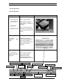
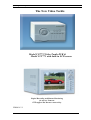
Operating Manual for CCT772 & CCT771 Video Tardis Manual
The New Video Tardis
Model CCT772 Video Tardis DVR &
Model CCT771 with built-in LCD screen
Digital Recording and Remote Monitoring
for up to 4 Cameras.
PTZ support and Internet connectivity.
VERSION 2.2
1
Operating Manual for CCT772 & CCT771 Video Tardis Manual
CONTENTS
Description
Page number
Contents
Operation Precautions
Accessories Checklist
Product Specifications
Product Features
Hard Disk Installation
CCT772 Front Panel Layout
CCT771 Front Panel Layout
Mouse Operation
Rear Panel Layout
25 Pin Alarm Transfer Box connections
System Operation
System Menu Structure
Recording Operation
Mouse and panel operation
Menu Option Schedule
System Operation Record Control
System Operation Record Playback
Playback Bar
Menu Operation
Network Connection
Network Operation - Web Browser
Backing Up Files
Playback of CR-ROM
Setting Up the Client Software
Frequently Asked Questions
Appendix A –Recording Times
02
03
03
04
04
06
07
08
09
10
11
12
13
14
16
17
21
22
23
24
34
37
51
52
53
55
56
2
Operating Manual for CCT772 & CCT771 Video Tardis Manual
Operation Precautions
l
l
l
l
l
l
l
l
l
l
l
l
l
l
l
l
All the safety and operating instructions should be read before the DVRs is operated.
All the safety and operating instructions should be retained for future reference.
Ensure all operating instruction and warning notes are complied with at all times.
Do not use strong or abrasive detergents when cleaning the DVRs.
There are no user-serviceable parts inside. Please contact a qualified engineer for
servicing
Do not expose the DVRs to water or moisture and do not try to operate it in wet areas.
Please make sure that both ends of the power lead are plugged in.
Do not drop foreign objects through the DVRs case or expose it to moisture.
Do not attempt to disassemble the DVRs, other than to fit the Hard Drives.
Contact a qualified engineer if the following situation happens:
Ÿ The power lead or plug is damaged.
Ÿ The DVRs has been exposed to rain or water.
Ÿ The DVRs does not operate normally by following the operating instructions.
Ÿ The DVRs is dropped or its cover is damaged.
When replacement parts are required, make sure that the service engineer has used
replacement parts specified by System Q Ltd or that these parts have the same
characteristics as the original ones. Unauthorised substitutions may result in fire, electric
shock or other hazards.
Never push objects of any kind into the case of the Tardis as they may touch dangerous
voltage points or short out parts that could result in a fire or electric shock.
If an outside cable system is connected to the Tardis, be sure that the cable system is
grounded so as to provide some protection against voltage surges and built-in static
charges. It is recommended that this unit is connected to a power surge protection unit.
All normal precautions to avoid component damage due to electrostatic discharge should
be taken during installation and operation.
To prevent electric shock, do not remove screws or the unit’s cover with the power
connected.
Do not cover the ventilation fan
Accessories Check List
1.
2.
3.
4.
5.
6.
7.
One Power Cable
One HDD Data Cable
One Standard Cat 5 Network Patch Lead (Not a crossover lead)
One Packet Of Installation Fixings
One CD For Installation of the Client software and the Player
One User Manual
One USB Mouse
3
Operating Manual for CCT772 & CCT771 Video Tardis Manual
Product Features And Specifications
Product Specifications
Parameter
Operation system
Models
Video input
Video output
Audio input
Audio output
Video display
Video standard
System resource
Image resolution
Motion detection
Video compression
Audio compression
Video recording speed
Image quality
Hard disk
HDD space used
Alarm input
Alarm output
Alarm relay
Port
USB Port
Network port
Pan-tilt control
Power
Power consumption
Working temperature
Working humidity
Barometric pressure
Size
Weight
4 Channel
Real-time operation system PSOS
CCT770/CCT771 DVR – The Video Tardis
4 Channels (NTSC/PAL) BNC 1.0VP- P 75
2 Channels PAL/NTSC BNC 1.0VP- P 75 and 1 Channel VGA output
2 Channels 200-2500mv 30K (RCA)
2 Channels 200-3000mv 5K (RCA)
1/4 windows display
PAL 625 line, 36f/s
4 x Channels Non real-time recording / 1 Channel real-time recording.
Video playback and Network operation
Real-time monitor 704×576 Video playback 1CIF 352×288,
Area setting: 192 detection areas on the screen; detection sense setting: 4 levels detection
sensitivity for each area
MPEG-4 CBR (fixed frame rate); MPEG-4 VBR (variable frame rate)
PCM
Total resources 36frames PAL mode
6 levels selectable
Internally equipped with 1 IDE port, supporting 2 drives
Audio 9.6 Mbyte/hour Video 56 ~ 250 Mbyte/hour
4 channel voltage alarm input
1 channel relay output, including one +12V output
30VDC 2A, 125VAC 1A relay output
RS232
2 x USB2.0 interface
RJ45 10M/100M Ethernet connection
RS485
220+25%V 50+2% HZ
20W excluding hard drive/s
-10°C ~ +55°C
10 ~ 90
86kpa ~ 106kpa
200 (wide) x275 (deep) x130mm (high)
5KG(not including hdd)
Product Features
Real-time Monitor
·Analogue Video output and VGA port
·Single window/4 windows monitor
.Realtime display of video bit rate and hard disk space usage per hour
.System log facility
Compression Method
·MPEG4
Storage
·1-2 IDE large capacity HDDs with infinite capacity
·Alternate HDD working method, reduce the power consumption and heat emission
·Overwrite and Stop modes, user selectable for when the HDD is full
.Backup via IDE port –USB port to storage devices
.Download files from DVR to local PC via network
Play and record
·Supports multiplex operation: live monitor, record, file search for downloading, one channel playback and remote
transmission simultaneously
.Network playback of files on DVR
.Quick search for all recordings
·Multiple playback modes: fast, slow, frame by frame, jump forwards/backwards
·Display original event time when playing back
4
Operating Manual for CCT772 & CCT771 Video Tardis Manual
Product Features Contd
Multi - Alarm
·4 channel external alarm input, motion detection alarm –alarm inputs could include: smog, temperature & infrared detectors
etc.
·Multi channel relay switch alarm output activates alarm relay and on-site light control
·Protection circuit for Alarm input and output to protect device
Communication connection port
·Supports the pan-tilt-zoom and alarm input via RS485 port communication
·RS232 port connected to PC for system maintenance
·Standard Ethernet port for remote connection and control via a network
.Supports high speed devices via two USB 2.0 ports
Network operation
·Remote real-time monitor via network
·Record search and real-time playback (playback quality depends on network capability)
·System setting modification and system software upgrading
·Remote alarm process and system log review
·Embedded Web server direct via Internet Explorer
·Administration mode: Two level network user administration; password to protect legal login
5
Operating Manual for CCT772 & CCT771 Video Tardis Manual
Installation.
Hard disk installation
If there is no hard disk fitted when initially purchased, check the hard disk equipment for the first installation. It
is possible to fit a maximum of 2 x 750GB capacity hard discs inside the machine. The user can decide the
number of hard disks according to required image quality, recording time and HDD capacity.
Installation Steps
Remove the fixing screws
securing the top cover
Install the first HD
(Master)
Replace the front cover
Dismantle the front
cover
Dismantle the HD
bracket
Fix the HD bracket
Install the second
HD (Slave)
Replace the top cover
and fixing screws
6
Operating Manual for CCT772 & CCT771 Video Tardis Manual
CCT772 FRONT PANEL LAYOUT
Key Functions
1. Up Direction Arrow (Press to select single window)
NOTE: Password Numeric Keys are used
for entering the two levels of passwords
2. Left Direction Arrow (Press to select single window)
3. Escape/Cancel Key
(See mouse and panel operation)
4. Down Arrow Direction (Press to select single window)
5. Enter/Cancel (Press to shift from 1 window to multi-window) (See mouse and panel operation)
6. Right Direction Arrow (Press to select single window)
7. Play Previous section (during playback) (Password 5 when not in playback mode)
8. Record
(Controls channels in preview mode)
9. Speed Up sequencing in playback mode – fast2 – fast3 (Password 4 when not in playback mode)
10. Function Key (Acts as right mouse button in preview mode and enters shortcut menu)
11. Play/Pause - shift between play and pause (Password 3 when not in playback mode)
12. Jump Forward (during playback)
(Password 2 when not in playback mode)
13. Go to next section (during playback)
(Password 1 when not in playback mode)
14. Power On/Off (Power off by pressing key for three seconds)
15. Channel Record Indicator
16. Channel Record Indicator
17. Channel Record Indicator
18. Channel Record Indicator
19. Power Indicator
7
Operating Manual for CCT772 & CCT771 Video Tardis Manual
NOTE: Password Keys are used for entering passwords
CCT771 FRONT PANEL LAYOUT
2
1
3
4
5
6
7
8
9
10
10
11
12
13
14
Channel
Record
Indicators
Key Functions
1. Power On/Off (Power off by pressing key for three seconds)
2. Function Key (Acts as right mouse button in preview mode and enters shortcut menu)
3. Record
(Controls channels in preview mode)
4. Up Direction Arrow (Press to select single window)
5. Left Direction Arrow (Press to select single window)
6. Escape/Cancel Key (See mouse and panel operation)
7. Enter
(Press to shift from one window to multi-window) (See mouse and panel operation)
8. Right Direction Arrow (Press to select single window)
9. Down Arrow Direction (Press to select single window)
10. Play Previous section (during playback) (Password 5 when not in playback mode)
11. Speed Up sequencing in playback mode – fast2 – fast3 (Password 4 when not in playback mode)
12. Play/Pause - shift between play and pause (Password 3 when not in playback mode)
13. Jump Forward (during playback)
(Password 2 when not in playback mode)
14. Go to next section (during playback) (Password 1 when not in playback mode)
NOTE: Password Keys are used for entering passwords.
8
Operating Manual for CCT772 & CCT771 Video Tardis Manual
Mouse Operation - (plug mouse into lower USB port)
Open password window if not logged in –enter main menu in monitor mode
Single click
left mouse
button
Enter sub-menu
Initiate instructions to confirm, cancel, save or default an operation
Change conditions of double chosen frame or motion detection
Open list when clicking assemble frame
Open number/abc panel when clicking EDIT, click numbers on the frame directly to
finish input. In abc input mode the following characters are:-
Delete one character
> and < capital lock shift
Symbol X means clear all contents
ü means confirm the input and close panel
q w e r t y u i o p
a s d f g h j k l
> z x c v b n m X ü
1
4
7
0
2
5
8
X
3
6
9
ü
Double click
left mouse
button
Special operations for controlling files e.g playback the section when double
clicking it
Single click
right mouse
button
Open short cut menu in monitoring mode:
SPLIT1
SPLIT1
>
SPLIT4
SPLIT4
QUICK SEARCH
QUICK SEARCH
REC CNTRL
REC CNTRL
CNTRL
PTZ CNTRL (provided protocol set) PTZ
COLOUR
COLOUR
MAIN MENU
ABOUT
MAIN MENU
ABOUT PTZ
CHN
CHN
CHN
CHN
1
2
3
4
COLOUR CTRL reflects current channel selected. It will automatically switch to the channel
selected in single screen mode if in multi-screen mode.
Mouse
Running
Roller
Move mouse
Drag mouse
Do not save menu content and quit
Change numbers when setting number frame
Shift options in assemble frame
Turn list pages
Click items and move
Click and drag menu title or control row, relocate when dropping
Frame motion detection area
Move window co-ordinate when clicking menu title and drag (not all windows)
9
Operating Manual for CCT772 & CCT771 Video Tardis Manual
Rear panel Layout
1
2
3
4
17
18
19
5
1.
2.
3.
4.
5.
6.
7.
8.
9.
10.
11.
12.
13.
14.
15.
16.
17.
18.
19.
6
7
8
9 ~ 12
13 ~ 14
15 ~ 16
Cooling Fan
Power socket
Power switch
Alarm - RS485 connector (15 way ‘D’type)
RS232 connector (9-way ‘D’type)
VGA port
Video Out 2 (BNC) (not operational with LCD display model)
Video Out 1 (BNC)
Video In 2 (BNC)
Video In 1 (BNC)
Video In 4 (BNC)
Video In 3 (BNC)
Audio Out 2 (RCA Phono)
Audio Out 1 (RCA Phono)
Audio In 2 (RCA Phono)
Audio In 1 (RCA Phono)
Network Port
USB connector Upper (USB for Backup Only)
USB Connector Lower (USB for Mouse Only)
Alarm In/Out and RS485 Connections –(25-way ‘D’type connector)
13 12 11 10 9 8 7 6 5 4 3 2 1
25 24 23 22 21 20 19 18 17 16 15 14
A 25 pin alarm transfer box is supplied with this DVR to provide alarm and RS485 connectivity.
The transfer box is fitted directly onto the back of the DVR using the two screws supplied and
plugs into the 25 pin connector. The green connectors can be easily withdrawn to fit cable
connections.
10
Operating Manual for CCT772 & CCT771 Video Tardis Manual
25 Pin Alarm Transfer Box connections
1.
2.
3.
4.
5.
6.
“Ground” : ground line
“+12V” : provide the power to alarm device
with current less than 2A
“OUT 2 1”
: are the two alarm outputs switch
Normally Open.
“485 A B”
: The RS485 communication for
PTZ control
“+12V(C)”
: Controllable power output alarm.
This alarm output could be used
for standby power for a smoke detector device.
“ALARM IN (1 ~ 8 ) voltage alarm inputs. The
input voltage is 5V ~ 15V but 12V is recommended.
+12V out
AB
8 7
6 5
4
3
2
The DVR requires +12volts for its alarm input trigger. A +12volt supply is available from the
DVR. This will be enough to operate approx 2 low current PIR devices (approx 50mA) as well as
providing the switching voltage. If an external power supply is used then remember to connect the
0volts to the DVRs Ground connection to provide a common reference.
See Examples 1 and 2 below:
Example 1 Wiring diagram to trigger alarm using 12v supply from DVR
Alarm In
DVR
RS485
Pins 1-8
PIR
+ 12v output
The above diagram shows a 12-volt alarm device being powered from the 25 pin alarm box on the rear of the
DVR. When the device is triggered 12volts is applied to the alarm input thus activating the DVR.
Example 2 Wiring diagram to trigger alarm using external 12v supply
Alarm In
DVR 12v
PIR
com
DVR
RS485
Pin
Ground
-0v
+12v
The above diagram shows a 12-volt alarm device being powered from an independent 12 volt power supply.
11
1
Operating Manual for CCT772 & CCT771 Video Tardis Manual
System operation
Before switching on the DVRs make sure that the Hard Drives have been fitted as required. Refer to Installation
for further details.
Turning on the recorder
Plug in the power cable; switch on the power button at the back of the recorder; at this point the power indicator light should
be on. The DVR will boot up.
Note: if the system stops during (Hard Disk Drive) detection, this means the HDD may not be installed correctly and
needs to be checked. See troubleshooting.
If the settings are still at default the system will start recording automatically. The display screen will come up in quad mode.
Press the Enter key or click the left mouse button to access the menu mode (the password screen will be displayed); the
corresponding channel indicator lights will be on. A Login dialogue box will appear to enter user name and password. The
default admin user will be displayed. Just enter OK as default password is “blank”.
LOGIN
admin
USER
PASSWORD
CANCEL
OK
There are no restrictions to the administrator rights whereas logging on via a user group only functions like SEARCH are
available. Other rights such as INFO, SETTINGS, BACKUP and ADVANCED however are restricted.
Note: For security reasons please change the default password. If you want to add a new user group, add new users or modify
the related parameters of a user group, refer to chapter on Mouse, panel and remote control operation.
To protect data stored from malicious interference it is advisable to always log out after finishing an operation and then
logging in again when access required.
SHUTDOWN
Turning off the recorder
Press the POWER key on the front panel for
3 seconds to stop the DVR. Then switch off
the power button at the rear to turn off the
power. Note: Always follow this procedure
to shut down the DVR correctly to prevent
data corruption.
After pressing the rear POWER switch the
user should wait for 5 seconds before trying
to restart.
Automatic Power off recovery
If there is power loss during normal operation
of the DVR, the recorder will preserve the
recorded information and return to the previous state and continue to work at the next restart. The state will be the same as it
was before the power loss.
Changing the Lithium Battery
If the unit time or date begins to show discrepancies, it may be that the lithium battery requires replacement.
Use a similar type of replacement battery. Whilst the battery should last a considerable time it is recommended
to check this on an annual basis.
12
Operating Manual for CCT772 & CCT771 Video Tardis Manual
System menu structure
Quick
SEARCH
List
HDD
BPS
INFO
M
E
N
U
General
Log
Encode
Version
Schedule
MD
SETTING
Alarm
Pan-Tilt
REC CHN
BACKUP
Network
Monitor
Default
Modify
User
Add/Del
HDD
ADVANCED
Update
EXIT
13
Operating Manual for CCT772 & CCT771 Video Tardis Manual
Recording operation
The default recording mode after starting the DVR is 24 hour continuous recording. The recording options are selected by the
user and are as follows:
Schedule recording
Enter the menu and set the time period for the recording. See details at MAIN MENU > SETTING > SCHEDULE.
Manual recording
Press [REC] on the front panel (record settings can only be made under the admin login), click right mouse button or press
[Fn] key to enter shortcut menu, select [REC CTRL].
Check the status of each channel in the recording menu, channels marked with ü are the channels set for recording.
Select the channel to be recorded (it will be
when in non-recording mode. Press the related number key
(or
, jog shuttle, mouse) to mark it with ü. Then press Enter to save settings.
Press again the related number key (or
, jog shuttle, mouse) to stop the recording of this channel.
Press [ESC] to exit, [Enter] to save the setting.
Alarm Recording
Alarm recording allows you to increase the recording time of the DVR, as it will only start recording when the PIR etc picks
up any movement.
Connect the alarm input device to the DVR according to the device connection instructions.
Connect the related alarm output e.g light, bleeper, etc.
Select the correct setting in the Alarm menu to start alarm recording. See details at MAIN MENU> SETTING > ALARM and
set alarm start and end time in MAIN MENU> SETTING > SCHEDULE.
Motion Detection recording
Motion detection recording will increase the recording time of the DVR, as it will only start the DVR recording when it picks
up movement.
Points to consider when using Video Motion Detection: - It is important to remember that the DVR’s VMD circuits look for
movement in the camera’
s picture, therefore if it is so dark that the camera cannot see any movement nor will the VMD
circuits. However, if you were using VMD in a darkened room as soon as the light is turned on, the VMD would cause the
DVR to record, as the change in light would be seen as movement. When you are using the VMD with external cameras,
sudden changes of bright sunlight to cloud, may cause the VMD circuits to trigger the DVR. With this in mind, outdoor use
of VMD needs careful planning.
In order for VMD to trigger the DVR you need to turn off schedule recording on the channel that requires VMD,
ensuring that you do this for each day.
Now you can turn VMD on.
Set up the required times and required motion detection setting in the menu. See details at MAIN MENU > SETTING >
MD.
Pan-tilt-zoom control operation
The Tardis range allows you to control Pan, Tilt & Zoom Equipment. It is possible to control PTZ equipment from the DVR
unit or you can operate it over a network connection.
Confirm the correct connection of the PTZ and the decoder, then set the correct decoder address.
You should enter the corresponding protocol of the PTZ equipment that you are using, from the MAIN MENU > SETTING >
PAN-TILT. Confirm the right connection of the camera's decoder A and B line and the DVR’
s A and B line on the 25 Pin
Alarm Transfer Box. To have control over the PTZ equipment you need to ensure that the monitor is in single window mode
(with the camera you require displayed). You should now press the function1 key [Fn1] or the right mouse button Select the
PTZ CTRL menu. Use the direction keys to move the PTZ equipment. Please note – The PTZ protocols are of a limited
range, therefore some functions that you can control on a PTZ keypad will not be available using the DVR.
Use [ I ] or [ I ] keynto move and control selections on
the screen including: direction, zoom, focus, iris & lamp.
Use [
] [
] [ ] [
] keys to move and control parameters.
14
Operating Manual for CCT772 & CCT771 Video Tardis Manual
Video Image Control Information
Click right mouse button or [Fn] key in monitor mode, select COLOUR CTRL and set colour, brightness, contrast and
saturation.
15
Operating Manual for CCT772 & CCT771 Video Tardis Manual
Mouse and panel operation
Menu settings
Operation
step
Button-pressing order
1 Click or press [ENTER]
2 Shortcut: right mouse button
Enter main
menu
MAIN MENU
Instruction
Re-login needed after restarting
system or logout.
Re-login and enter main menu.
(Display on right shows menu when
clicking right mouse button)
Enter level
1.Press direction keys (jog
shuttle)
1
pqut
submenu
or move mouse
2. Click or Press [ENTER]
Shift main menu options
Enter the selected level 1
submenu
1.Press direction keys (jog
shuttle)
pqut
or move mouse
Shift level 1 submenu options
Enter level
2 submenu
Set
menu
contents
Exit
menu
Click or press [ENTER]
Enter the selected level 2
submenu
1. Press direction keys ut
Select the level 2 submenu option to be
changed. Selection is highlighted.
or move mouse
2. Press ut or roll mouse
Revise menu contents, press ut to the
next option to reverse after finishing
3. Click mouse or press
[ENTER]
Press [ENTER] to save setting or execute
default. If combined with number keys or
software disk ( click edit menu or enter)
Press [ESC] or click right
mouse button
Exit to the last level menu
16
Screen display
Operating Manual for CCT772 & CCT771 Video Tardis Manual
You can perform multiple channels setting before exiting the same level menu and save the settings altogether
Menu option schedule
Main menu
Menu level 1
Remarks
QUICK
SEARCH
SEARCH
Positioning playback by channel or time
Search by recording type :- (all, alarm, motion detection) ,
channel and time.
Rapid Search
List Search &
Playback
Function
Results are listed.
Select file for playback.
Hard Disk number, Total capacity, Capacity left,
Start & end time of recording
BPS
Current bit rate on each channel and hard disk space occupation,
Wave image display etc.
Look up
hard disk
info, bit rate
stats, alarm
condition
and version
etc.
LOG
Display login and out time of all users
Display system hardware resource, hardware version, software
version and software published date etc.
17
Operating Manual for CCT772 & CCT771 Video Tardis Manual
Menu option schedule (cont.)
Main Menu
Level 1
GENERAL
Remarks
Set basic parameters: system time, date & time format,
language version, video mode and DVR item number.
If video mode is changed the system will automatically
restart.
Basic system
channel parameters,
image coding /
decoding
parameters,
schedule, motion
detetction, alarm and
monitor parameters
setting.
ENCODE
Set AV parameters: coding mode, frame rate, image
quality, bit rate control, resolution and sampling rate.
SCHEDULE
Schedule set for recording, motion detection, external
alarm, & time zone for daily operation. Note two time
zones can be allocated for each channel per day.
Motion Detect
Set motion detection parameters: channel, sensitivity,
region and processing. (alarm output and time lag switch)
Set parameters including alarm input and condition, alarm
time lag, screen inform, alarm output and condition.
18
Operating Manual for CCT772 & CCT771 Video Tardis Manual
CHANNEL
Set input channel and name
PAN-TILT
SETTINGS
Set channel pan-tilt protocol, protocol decoder address,
baud rate and data format
NETWORK
Set network parameters including IP address and video
data transmission protocol.
MONITOR
Set menu output and monitor sequence mode parameters.
Note: menu output attribute changes will be effective
when system restarts.
This option sets manufacturers default settings.
DEFAULT
BACKUP
Note: menu colour, language and video mode will stay
unchanged.
Check backup device, select backup division, record channel, time and type.
After setting, find recording files on hard disk and backup to USB storage
device.
19
Operating Manual for CCT772 & CCT771 Video Tardis Manual
UPDATE
ADVANCED
Software upgrade via U directory. Upgrade program will only
be found if under U directory on USB device when unit
restarted.
Software upgrade,
HDD
This option allows setting hard drive working mode, the
recording file size and hard disk format.
HDD settings and
NOTE: Hard disk changes are effective when system restarts.
MODIFY
user management.
Set “user”and “administrator”password.
USER
Create new user, distribute user limits, set
ADD/DEL
Password, delete selected user.
EXIT
Logout, shutdown system, restart system.
20
Operating Manual for CCT772 & CCT771 Video Tardis Manual
System Operation
Record Control
Operation
1.
Instruction
MAIN MENU >
Press to enter screen display
SETTING >
(input password in logout
REC CHN
Screen Display
condition)
or right mouse button
REC CTRL
REC CTRL
2.
3.
directions
Press to set channels on or off
[p] [q]
for recording.
+ [Enter] or click mouse
Image on right shows all
channels are in record mode.
directions
Press to select recording
channel
[u] [t]
4.
save
Press [Enter] to save setting
21
Operating Manual for CCT772 & CCT771 Video Tardis Manual
System Operation
Record Playback
Operation
Instruction
Screen Display
Enter screen display:
1. Enter playback:
Set search time, press
[play/pause] / [Enter] to
playback.
MAIN MENU
>
SEARCH >
Note: This operation is
invalid if recorded file in
search time entered is not
found.
QUICK / LIST
2. Operate
playback
frame
Playback recording
(screen displays channel,
date, time, playback
speed and progress) and
controls speed and
channel.
mode
Playback bar
Press Switch Channel
key to shift relative
channel recording
simultaneously with
current playback channel.
3. Simultaneous
channel shift when
playback.
PRECEDING SEGMENT
PLAYER BAR
RESTORE NORMAL
FRAME FORWARD
PLAY/PAUSE
STOP
SWITCH
CHANNEL
NEXT SEGMENT
SPEED UP
JUMP BACKWARDS
LOWER SPEED
DISPLAY AREA
BUTTON
BACKUP
22
JUMP FORWARD
FRAME BACKWARD
Operating Manual for CCT772 & CCT771 Video Tardis Manual
Playback Bar
Operation
1. pause/play [u|| ]
Instruction
Press to move between play and
pause
2. stop [
Press to stop playback
]
Remarks
3. previous section [ |t ] Press to choose different sections in
current channel
next section [u| ]
4. switch channel
Press to select relative channel
5. reverse
Press to playback in reverse
6. speed down [ u]
Press to change playback speed: total
4 levels: slow 1 / 2 > slow 1 / 3
Slow 1 / 3 means 1/3 of
normal speed
7. speed up [u]
Press to change playback speed: total
2 levels: fast2 > fast3
fast3 means 3 times
normal speed
8. restore normal [p]
Click to go back to normal mode
from any abnormal playback mode.
.
9. play forward, frame
by frame [uu| ]
Press to play frame by frame
manually (key frames per second) :
including forward and reverse play.
play reverse, frame
by frame [|tt]
10. forward [uu]
Press to change between forward and
rewind.
rewind [tt]
Note:
1.
2.
3.
4.
In playback mode, control frame will show file play speed, channel, time and play process.
Reverse function, manual frame by frame playback function and playback speed depends on machine version.
The rapid change from abnormal playback to normal mode is available by mouse and panel operation.
Circle playback is accepted in any mode. System will play the first section in the list if the last one is complete but
auto replay if only one file is playing.
23
Operating Manual for CCT772 & CCT771 Video Tardis Manual
MENU OPERATION
MAIN MENU
LOG IN
Log In, press [Enter] / click left
mouse button / click right mouse
button > MAIN MENU
SEARCH
Six menu options displayed :
SEARCH
INFO
SETTING
BACKUP
ADVANCED
EXIT
BACKUP
SEARCH MENU
INFO
SETTING
ADVANCED
EXIT
SEARCH
Search files using QUICK and
LIST modes depending on record
type, channel and time.
Note: Choose file, press [Enter] to
play.
QUICK
LIST
Search according to channel and time
QUICK
Search and playback recorded files
by channel and time.
Press
time.
Press
tu
to choose channel and
pq
to change content.
Press [Enter] to play back.
24
Operating Manual for CCT772 & CCT771 Video Tardis Manual
LIST
Search by recording type: all,
alarm, motion detection, all alarm
record, record channel, start and
end time of recording –shows
results in a list.
Set channel, date, time –
Press SEARCH
screen shows a list –
Press t u to select a file –
Press [Enter] or click PLAY to
play file.
INFO MENU
Four menu options are displayed :
HDD
BPS
LOG
VERSION
Note: These menus only available to
Admin users.
HDD
Shows HDD ID number, total capacity,
capacity left, start and end time of
recordings.
Note: If you need to replace a faulty
hard drive, power down and remove
the faulty drive before installing the
new one. If hard disks conflict when
starting system, check that the time in
system and hard disk is the same. If not
then enter GENERAL menu to set
system time and then restart DVR to
secure changes.
25
Operating Manual for CCT772 & CCT771 Video Tardis Manual
BPS
Realtime display shows channel video
bit rate (B/S) and hard disk space
(B/H). Some versions of software
support a bit-rate wave shape chart.
LOG
Displays log of all user log-ins
including: username, limit, log-in time
and log-out time.
Press t or u to choose user.
Note: Information display screen will
show all the operations in the period
(from login time to log-out time)
VERSION
Display hardware sources (channel
numbers, alarm input/output channel
numbers), hardware version, software
version and publish date.
26
Operating Manual for CCT772 & CCT771 Video Tardis Manual
SETTING MENU
SETTING MENU
Ten menu options are displayed :
GENERAL
ENCODE
SCHEDULE
MD
ALARM
REC CHN
HDD
NETWORK
MONITOR
DEFAULT
Note: These menus only available to
Admin users. Press SAVE to
activate new settings.
GENERAL
System time: set system date & time
Date format: select: yy-mm-dd,
mm-dd-yy, yy/mm/dd,
mm/dd/yy
Time format : 24hr and 12hr
Language: English, Chinese
Video mode: PAL and NTSC
Item number: for one remote control
NOTE: DO NOT CHANGE DATE
OR TIME AS RECORDED DATA
MAY NOT BE ACCESSIBLE
ENCODE
Video channel: select channels
VIDEO SETTING:
Coding mode: MPEG4
Resolution: CIF
Bit rate control: CBR or VBR
Frame rate: 1~3 f/s, 6f/s, 12f/s,
25f/s
Image quality: 1~6 levels ( 6=
best)
AUDIO SETTING
Audio channel: Ch1, Ch2, close
Compression mode: PCM
Sampling rate: 8KHz
BITS: 16 digits for each sample
NOTE: There are 4 video channels & 2 audio channels. Two channels
are closed when all 4 channels are recording.
27
Operating Manual for CCT772 & CCT771 Video Tardis Manual
SCHEDULE
Includes timing recording, motion
detection & external alarm –maximum
2 time zones per day.
Channel: select channel
Day of week : set time for each day
Time section 1 , Time section 2 :
Start and finish time for recording.
Allows two time periods to be set per
day. If start time not earlier than end
time, end time will be switched to start
time. If only one time period required
per day then only select Time 1.
MD
Motion Detection.
Channel : select MD channel
Region : move cursor to SET, press
[Enter]. Screen divided into 192
regions. Green frame squares show
cursor position. Coloured region is the
area tested for motion detection. The
transparent area is not motion detected.
Press SAVE to save setting.
Sensitivity : high, normal, low
Recording channel : select channel/s to
be recorded.
Alarm output : switch output alarm
device.
Alarm time lag : time recording in
seconds after MD complete –10 secs ~
300 secs.
Screen display : [P] means MD info on
screen.
NOTE: It is easier to use the mouse for setting Motion Detection.
When settings complete ensure to press SAVE.
Setting up Motion Detection
To change schedule recording to motion detect enter the Schedule, select RECORD top right
and then select each channel in turn and un-tick each day scheduled and SAVE . Now go
into the. MD menu and set the channels for motion detect and save. Now return to the
Schedule, select MD top right and then select each channel in turn and tick each day for
motion detect, then SAVE. Do not select ALL as this will reset the time settings in MD and
will reset the schedule to normal recording.
Recommendation: Before making changes it is advisable to set the General menu
settings first to 24 hour time format. If you change settings in the General menu it is
advisable to set all recordings to off first, then go to Advanced menu –HDD –and
format hard disk. After reboot make changes to General menu settings and switch on
recordings.
28
Operating Manual for CCT772 & CCT771 Video Tardis Manual
ALARM
Alarm Input Info:Alarm input: select alarm channel
Device type : open / close
Channel selection : select recording
channel (s). Channel will record
automatically when alarm is on.
Alarm time lag : auto set time lag
10~300 secs after alarm cancelled.
Pre-recording: [P] means function on
Alarm output : [P] means alarm out on
Screen output : [P] means function on.
Alarm Output Info:Alarm output channel : select channel
Alarm switch : [P] means function on.
Device type : open / close
REC CHN
Select Record Channels
Channel: select channel/s
Channel status : [P] means channel on
Title : channel title e.g CHN1
PAN-TILT
Channel : select channel with PTZ
Protocol : select protocol from list
Address : select PTZ decoder address
Baud rate : select baud rate
Data position : select data position
Stop position : select stop position nos.
Check : odd/even
29
Operating Manual for CCT772 & CCT771 Video Tardis Manual
NETWORK
Net Layer:
IP Address: set IP address
Subnet mask : set Subnet mask
Default gateway : set default gateway
Transfer Layer:
Protocol : TCP
HTTP port : set port, default 80
TCP/UDP port : default 37777
Note: set local connection protocol as
TCP when monitoring via WAN
MONITOR
Menu output:
Transparency : 0 ~ 255
Time title : [P] means no time
information output.
Auto log-out : 5mins, 10 mins, 15 mins,
20 mins, 30 mins, 60 mins and no auto
log-out.
Monitor output:
Screen mode : single & multi-screen
Circle mode : non-circle, circle 5, 10,
15, 20, 25, 30 seconds. (circle means
sequencing)
4 windows : [P] means 4 window
monitor circle output is on.
1 window : [P] means single monitor
circle output is on.
DEFAULT
Set system default settings.
30
Operating Manual for CCT772 & CCT771 Video Tardis Manual
BACKUP MENU
Target device : select target backup
device (USB storage device)
Target division : select target division
Target channel : select backup channel
source.
Record type : select record type including
alarm records, motion detection and all
records.
Start time : select start time of backup
record
End time : select end time of backup
record.
NOTE: Option only available to admin
users.
ADVANCED MENU
Three menus are displayed:
USER
HDD
UPDATE
NOTE: Option only available to admin
users.
USER
Click on USER to show two menu
options.
MODIFY
ADD/DEL
31
Operating Manual for CCT772 & CCT771 Video Tardis Manual
MODIFY
User name : enter login user name
New password : enter new password –
(1 ~ 6 digits)
Confirm password : re-enter password
NOTE: Option only available to admin
users.
Press [Enter] to confirm.
ADD/DEL
User name : enter new user/user to delete.
New password : set new user password
(1 ~ 6 digits)
Confirm password : re-enter password
User limit : select user for limited rights or
Administrator for full rights
Add : Press ADD to finish setting
Delete : Press DELETE to delete
password
HDD
Channel : select hard disk number
Work mode : MASTER/SLAVE
Write mode : OVERWRITE/STOP
(set to STOP unit will not overwrite HDD)
Record size : 20 min
Format : Press FORMAT to format HDD
Press [Enter] to proceed
NOTE: Formatting will remove all data on
HDD.
32
Operating Manual for CCT772 & CCT771 Video Tardis Manual
UPDATE
This option allows the installing of new
BIOS software upgrades. The software is
downloaded from a PC using a USB
connection and entering this menu. The
BIOS upgrade must be saved in the U:/
folder on the PC.
Open : Press OPEN and DVR will search
for BIOS upgrade in U: drive on PC. If
software not found upgrade will fail.
NOTE: Do not stop upgrade during update
as this may corrupt machine BIOS.
EXIT
This menu has three options:
LOGOUT
CLOSE SYSTEM
RESTART SYSTEM
Click on drop down arrow to select option
required.
Logout : Quit menu, enter password to reenter.
Close system : Quit and switch off power.
Restart system : Quit and restart system.
NOTE: Available to users and
administrators.
33
Operating Manual for CCT772 & CCT771 Video Tardis Manual
Network connection operation
The Tardis can be networked in three different ways; Direct connection, LAN connection or Internet connection.
Direct Connection via a crossover cable
It is possible to connect the DVR directly to a PC that has a Network Interface Card. It must be connected to a P.C using a
network crossover lead. This lead (NET992) can be purchased from your supplier. You must give the DVR an Internet
Protocol (IP) address e.g 192.168.000.005. The DVR default IP address can be found by Entering main menu > settings >
network. The subnet mask should be set to 255.255.255.0 Leave the Default Gateway blank. Power down the Tardis to
register the changes. Hold the front power button for 4 seconds, then switch off at the rear. Now power back on at the rear of
the DVR and the unit will reboot. Now set the PC with a unique I.P address but in the same range as the DVR e.g
192.168.000.010. To set the IP address in the PC go to Control Panel > Local Area Connections then Properties > Highlight
Internet Protocol (TCP/IP) then click Properties again > click “Use the following IP address”. Set the IP address and subnet
mask. Again leave the Gateway blank. Now load the DVR365 client and player software. Load the client software from the
CD provided with the DVR. Now double click the program icon. The software will require the DVR I.P adddress e.g
192.168.000.005 and the subnet mask. Login by setting User admin only. Leave the password field blank.
Local Area Network via a hub, switch or modem router
You can connect the DVR to a Local Area Network (LAN) using the connection port on the rear of the DVR. You must use a
LAN cable as per the one supplied with the unit. You must give the DVR an Internet Protocol (IP) address. This must be
unique to your network but in the same range as the Router’s IP address. For example if the Router’s default IP address is
192.168.000.001 then use the same first three levels of the IP address i.e 192.168.000 but give the last level a unique value
e.g 192.168.000.005 If the Router’s default IP address is 192.168.001.001 then use an IP address in the DVR e.g
192.168.001.005 The subnet mask should be set to 255.255.255.0 The Default Gateway should reflect the Router's IP
address.
Power down the Tardis to register the changes. Hold the front power button for 4 seconds, then switch off at the rear. Now
power back on at the rear of the DVR and the unit will reboot. Now set the PC with a unique I.P address but in the same
range as the DVR e.g 192.168.000.010. To set the IP address in the PC go to Control Panel > Local Area Connections then
Properties > Highlight Internet Protocol (TCP/IP) then click Properties again > click “Use the following IP address”. Set the
IP address, Subnet mask and Gateway address.
To set the IP address in the PC go to Control Panel > Local Area Connections then Properties > Highlight Internet Protocol
(TCP/IP) then click Properties again > click “Use the following IP address”. Set the IP address, subnet mask and Gateway.
The Gateway is the Router’s IP address. Now load the DVR365 client software from the CD provided with the DVR. Now
double click the program icon. The software will require the DVR I.P adddress e.g 192.168.000.005 the Subnet mask and
Gateway addresses. Login by setting User admin only. Leave the password field blank.
In order to confirm the correct network connection between DVR and computer, you can use the PING command that comes
with Microsoft Windows systems. To access the PING command, follow the sequence below: Start > Programs >
Accessories > Command Prompt. Once Command Prompt is open type (if 192.168.000.005 is the IP address of the DVR):
PING 192.168.000.005
If it comes back and says ‘Request Timed Out’then the two devices are not communicating/connected correctly. This could
be due to a bad or incorrect cable connection or the incorrect IP addresses. If it comes back and says ‘Reply from
192.168.000.005’the two devices are connected correctly.
Internet Connection via a modem router
CHECK LIST –for getting a Video Tardis on to the Internet
You need a broadband (ADSL) internet connection at the site where the DVR is to be installed.
The ADSL connection at the site where the DVR is installed should have a “STATIC IP address”.
(Note - you can request a static IP address from most Internet Service Providers (ISP’s), but they may charge a small fee
for this.)
You will need a broadband router/modem at the DVR site. A good one is the NET800.
At the remote site where your computer will be located you will also need a broadband connection to ensure that you have a
fast connection to your DVR.
TIP - You can’t use a USB type modem connected to a stand alone PC to get the Tardis connected to the internet, you must
get a router-modem, that allows multiple computers to share the broadband ADSL connection. USB modems rely on a
computer’s operating system to drive them and the DVR365 cannot do the same thing.
Once you have got your ADSL Internet connection with a static IP address at your DVR site, you can progress to installing
the DVR.
If the site where the DVR is to be installed already has an ADSL Internet connection that is shared by one or more
computers it is likely to already have an ADSL modem/router of some description. If this is the case you will have to
34
Operating Manual for CCT772 & CCT771 Video Tardis Manual
either configure the existing modem/router or replace it with a new one. If it’s an existing installation, we strongly
recommend you enlist the help of the person or company that installed and configured it originally.
The rest of these instructions now refer to installation using the NET800 modem/router.
Step 1 Getting the NET800 router-modem connected to the Internet
If you have already done this and can already “surf the internet”you can skip this section and go straight on to the next step.
Your ISP should have given you all the information you need to get your modem and computers connected to the Internet.
You should have the following information;
login user name
password
static IP address
Connect your computer to the NET800 modem router using the blue STRAIGHT RJ45 cable supplied with the router. Next,
you need to set up the router to connect to the Internet. See the NET800 instructions of how to do this.
Once you have set up your router to work with a static IP address anyone who types this address into their web browser will
be re-directed to your router from anywhere in the world. The next task is to make the router “route”this request to the DVR.
Step 2 –Setting up the DVR
The DVR needs to be connected into the same network as the NET800 router or directly to the router itself. To connect into
the network or directly to the router, use the “straight”grey RJ45 cable supplied with DVR. (Note when you are connecting
the DVR directly to a computer with no router you need a “crossover cable”.
In the DVR you need to set up its IP address to be the same address as you set the DMZ server to be in the NET800 router. In
this example, both the DVR’s IP address and the DMZ server’s need to be set up to be 192.168.001.005. Also, you will set up
the DVR’s “gateway”as 192.168.001.001. The Static IP address supplied by your Internet Service Provider does not have to
be specifically entered as this will be automatically determined by the NET800.
To get into the DVR menu press “enter”followed by the User admin. Leave the password field blank unless you have set a
password. Now navigate to Settings>Network
In Network enter the details as follows:
NETWORK
NET LAYER
192
168
001
005
SUBNET MASK
255
255
255
000
GATEWAY
192
168
001
001
IP ADDRESS
TRANSFER LAYER
PROTOCOL
TCP PORT
HTTP PORT
SAVE
TCP
37777
00080
CANCEL
DEFAULT
TIP- we recommend you do not change the subnet mask, as this is the default setting for most networks.
After you have changed and saved the network settings in the DVR (such as the IP address) you MUST reboot the DVR for
these changes to take effect. Obviously please make sure you save the settings before you reboot!!m/router you will need to
test it from another broadband connection to make sure it is working correctly.
Whilst we can help with the DVR settings, it is the ISP's responsibility to advise on the setup of your ADSL connection.
35
Operating Manual for CCT772 & CCT771 Video Tardis Manual
Step 3 –Setting up the PC
To set the IP address in the PC go to Control Panel > Local Area Connections then Properties > Highlight Internet Protocol
(TCP/IP) then click Properties again > click “Use the following IP address”. Set the IP address, subnet mask and Gateway.
The Gateway is the Router’s IP address. Now load the DVR365 client software from the CD provided with the DVR. Now
double click the program icon. The software will require the DVR I.P adddress e.g 192.168.001.005 the Subnet mask and
Gateway addresses. Login by setting User admin only. Leave the password field blank.
In order to confirm the correct network connection between DVR and computer, you can use the PING command that comes
with Microsoft Windows systems. To access the PING command, follow the sequence below: Start > Programs >
Accessories > Command Prompt. Once Command Prompt is open type (if 192.168.001.005 is the IP address of the DVR):
PING 192.168.001.005
If it comes back and says ‘Request Timed Out’then the two devices are not communicating/connected correctly. This could
be due to a bad or incorrect cable connection or the incorrect IP addresses. If it comes back and says ‘Reply from
192.168.001.005’the two devices are connected correctly.
36
Operating Manual for CCT772 & CCT771 Video Tardis Manual
NETWORK OPERATION
Web Browser
The Client software does not need to be pre-installed. You can connect to this DVR
using the Web Browser. If you cannot get a connection then to refer to the previous
instructions.
LOGIN and LOGOUT
Enter the IP address of the DVR into the address line of the Web Browser. For
example if the DVR IP address is 192.168.0.5 then enter http://192.168.0.5 into the
browser address line. The first time this is run a dialogue popup box will appear
asking if you wish to accept ActiveX. If you reply YES, the system will install the
software automatically.
Using this interface you will see the following menus displayed across the top of the
player window: Login : Logout : Video : Search : Config : Assistant
Login : Click Login and the following dialogue box will appear:
Input the username and password. There are
three levels of users : Administrator, User and
Guest. For detailed introduction see section
on User Manage in Assistant setting. The
default username = admin. The default
password is left blank.
192 .168 .0 .5
37
Operating Manual for CCT772 & CCT771 Video Tardis Manual
If the following dialogue box appears after inputting username and password, the
system is indicating that the user has already logged on. Please log in using an
alternative username.
If the following dialogue box pops up after inputting username and password, the
system is indicating an invalid username or password has been entered.
Log out : To logout please click the Logout button. When the Logout dialogue box
pops up, select Yes to Logout.
38
Operating Manual for CCT772 & CCT771 Video Tardis Manual
Once you have logged in as administrator the buttons Login, Logout, Video, Search, Config
and Assistant are activated. Click the mouse right button and the following menu will be
displayed:
192.168.0.5
Real Time Monitor >
Decode Quality >
Playback control Bar
Pan-tilt Control
Set Volume
Net Data Flux
Full Screen
Resize Video >
Video Windows >
Uninstall Webrec.ocx
CHN1
CHN2
CHN3
CHN4
Real Time Monitor
This option allows you to select one of the four channels for monitoring. The channel name
can be changed in the Assistant menu. If you right click the channel number an additional
menu selection can be made available. The Prearrange set menu is inserted between Decode
Quality and the Playback Control Bar menus. See details below in Pan-tilt Control option.
Access will depend on your control rights.
Decode quality
Set the required decode quality.
There are four levels to choose from.
Playback Control Bar
See instructions on Playback Bar.
Pan-tilt Control
This allows the movement of the PTZ
unit and includes zoom, focus and
aperture settings. In order to use this
facility you have to setup the PTZ
menu for the address, protocol and
baud rate of the PTZ unit in the DVR.
A tour can be controlled by setting
presets and then ticking the tour box.
See the Prearrange set menu below.
39
Operating Manual for CCT772 & CCT771 Video Tardis Manual
Move the camera to the prearranged position, then preset
the position. Several positions can be chosen. If the check
box near tour checked, the PTZ will cruise automatically
between these positions.
Set Volume
This option control the audio volume. Drag the bar to adjust the volume or tick the Mute box
to mute the sound.
Net Data Flux
This options displays the network transmission data flux rate. When no network data transfer
is occurring the display will show a zero rating.
40
Operating Manual for CCT772 & CCT771 Video Tardis Manual
Full Screen
There are two ways to select a full screen display. One is to double click the window directly;
the other is to select Full screen in the right key menu. In multi-window mode, choose a
window and double click in it.. It will then change to full screen mode.
Resize video
In single window mode, the user can alter the video window ratio
and size. In multi-window mode the user can see the change made.
Video windows
There are a selection of options. Either One window, Two windows, Four windows, New
Video Window, Close Video Window and Arrange in full screen
New Video Window
When the number of video windows is less than 4, you can add a new video window
manually.
Close Video Window
Close window monitoring.
Arrange in full-screen
If two or more windows are displayed, you can use this option to display multiwindow in full screen.
Uninstall Webrec.ocx
Uninstall the Active X webrec.ocx before you upgrade the new web Active X.
SEARCH
Click on SEARCH and the following pop-up box will be displayed:
41
Operating Manual for CCT772 & CCT771 Video Tardis Manual
Now fill in the required info in the pop-up dialogue box. Select the Type of file being
searched. This can be a schedule recorded file (Record), an Alarm record file (Alarm) or a
motion detect file (Motion). Now enter date and time of start of selected incident in the From
boxes, the end of the selected incident in the To boxes and the selected channel. Press Search
and a list of the files found will be displayed in the Result screen. If only the From date and
time is entered the Result screen will display all files for a 24 hour period from the time
entered. The display will show only 15 files per page. Press Page Up or Page Down to scroll
through pages of files found. Now double click the selected record and the file will be played.
During the playback, you can operate the buttons in the playback bar like save record, stop
save, capture picture, full screen. During playback on the video screen, the video displays the
channel number, time and data flux of the record.
Save record stop save
capture picture
full screen
At the same time you can also perform a download to the C: drive on your P.C.
by pressing the Download button.
The filename will be downloaded to the PC under the default drive C:/ or
drive/folder set on installation. Note that the file dialogue box allows you to
enter a name for the downloaded file - for example Fred. The filenames
downloaded will be in the following format:
C:/Program Files/Software Tools/DVR365/download/Fred20060823113025[1].mpg
*Note: Different versions of the software may produce
Fred-20060823113025[1].mpg
.MP4, .dav or .mpg files. You can only playback these file/s
Fred = saved file name
using the DVR365 Client or Player software as the files are
encrypted. The Player software downloaded from our
2006
website will allow you to re-record these files as AVI files
08 = Month
for use with MS Media Player. MS Media Player will need
the correct CODEC downloadable from the Microsoft
23 = Day
Website.
11 = Hours
30 = Minutes
25 = Seconds
[1] = file number
.mp4 = File Type *
Ensure you save the files. If you click the Download Together box you can
select a number of files using the CTRL key and data will be written to one
file.
42
Operating Manual for CCT772 & CCT771 Video Tardis Manual
CONFIGURATION
Click on Config and the DVR Menu will be displayed:
There are six submenus displayed. They are
GENERAL, SCHEDULE, IMAGE, ALARM,
MOTION DETECT and VIDEO PARAMETER.
At the bottom of each menu page there is a SAVE
button. If you wish to save into the whole
configuration table press SAVE CONFIG. If you want
to reload the complete configuration table then press
LOAD CONFIG.
GENERAL
Disk Full - set to OVERWRITE or STOP
Remote –set to 8 for use with a remote control
IP Address –Greyed out –only modified at DVR
Serial - Record length setting –set record time length
Control PTZ –Set channel, protocol, address & baud
rate
SCHEDULE
The SCHEDULE menu allows you to set
per channel, the day of the week and the
time period for continuous recording.
There are two time periods per 24 hour
period for continuous recording. The two
slots must not overlap each other. If
continuous 24 hour recording is required
use only Time 1 slot and set State to ON.
A similar menu setting is available for
setting Motion Detect. Again there are two
time periods available per 24 hour period.
Set the STATE to ON for the required
timeslot. Ensure that slots do not overlap
each other.
NOTE: You must not overlap any
timeslots across the SCHEDULE and/or
MOTION DETECT timeslots.
43
Operating Manual for CCT772 & CCT771 Video Tardis Manual
IMAGE
This menu can select the channel, frame rate,
bit transfer method and resolution quality and
you can set the option to alarm you when a
video loss on this channel is detected. Click
Save to save the setting of this channel.
Finally, click Save Config to save all settings.
Channel –select channel number
Rate – The Frame Rate for this channel. The
total frame rate for this unit is 50FPS (frames
Per Second) but you must deduct 14FPS for
the two audio channels. This leaves a total of
36FPS over four video channels. You can
select variable frame rates for each channel up
to the total of 36FPS. E.g CH1-25, CH2-3,
CH3-4 and CH4-4 FPS.
Select from1/10, 1/5, ½, 1, 2, 3, 4, 5, 6, 8, 10,
12, 15, 20 & 25 Frames Per Second.
Style –Set to VBR (Variable Bit Rate) or
CBR (Constant Bit Rate). Use VBR for
network access –LAN or WAN.
Quality –Image Quality –set from 1 ~6.
When in VBR style, there are 1,2,3,4,5, & 6 levels of image quality. Level 6 is the highest
quality but transmission loading is also the highest. When in CBR style, the selectable data
flux settings are 128Kb/S, 256Kb/S, 384Kb/S, 512Kb/S, 768 Kb/S or 1024Kb/S.
Alarm when video lost
Off means no alarm. On means alarm when video lost.
Network Transport Protocol
Monitor and Playback
Only the TCP protocol is supported. A maximum of two TCP users are allowed.
44
Operating Manual for CCT772 & CCT771 Video Tardis Manual
ALARM
When there are alarm input signals, the user
can select the recording channel and the
output port. There are 8 alarm input ports on
this unit and 2 alarm output ports.
Alarm Port Set alarm input port –channel
1 ~ channel 8.
Record Channel –select record channel 1 ~
4 for channel to record.
Output Port –select output port 1 or 2 for
triggering output device.
Click SAVE to save menu page.
MOTION DETECT
When the user sets an MD time period
(the time period cannot overlap any
schedule time recording. The schedule
recording always takes higher priority)
motion detection will take effect.
The purple area in this menu is the
selectable motion detection area. Users can
move the cursor to select any area where
MD is not required e.g bushes and trees or
across lower section of display avoiding
movement by animals, and can also set the
sensitivity of the area.
Full Screen –Click Full Screen or press
right mouse key on motion detection area
to display full screen detection area.
Channel –Enter channel for MD
Delay time –This is the time in seconds
unit will continue recording following end
of MD. Recommend setting at 180 secs.
Sensitivity - MD sensitivity Low, Normal
or High.
Alarm Output –Set alarm output channel
when MD is activated.
Recorded Video –set channels to record
when MD activated. If you use this ensure
that scheduling recording is set off.
Save Channel or Clear –After setting
MD area click on Save Channel or Clear to
clear setting.
Save –save all settings
6-
45
Operating Manual for CCT772 & CCT771 Video Tardis Manual
VIDEO PARAMETER
Configure the video parameters including
Hue, Contrast, Brightness and Saturation for
the respective channel. Click reset to return
to factory default. Click SAVE to save
channel and SAVE at bottom of menu to
save all settings.
OSD Height
1
OSD show
ON
6-
46
Operating Manual for CCT772 & CCT771 Video Tardis Manual
ASSISTANT
C
C
Click on the Assistant setting and the menu
on the right will be displayed. The
following option headings are described in
detail but summarised as follows:
User Manage
Record Control
Apply for Control Right
User Manage –set users and their rights
Record Control –Emergency manual
record option
Apply for Control Right –force control
Log Information –system log info
System Information –basic system info
Alarm Prompt –select audio alarm sound
Channel Name –set a name for a channel
Upgrade BIOS –upgrade BIOS & Web
Software
About DS-IRECClient -
Log Information
Digital Video Recorder
System Information
USER MANAGE
Displays user information. The right buttons
can let an administrator user save, add,
modify, delete and cancel the information.
Three user levels: Administrator fully set
the system and modify any user information;
User can not set system parameter and
modify other users’information; Guest can
not set system parameters and search records.
Can only modify personal information.
You can Add, Modify or Delete user
information.
47
Alarm Prompt
Channel Name
Upgrade BIOS
About DS-IRECClient
Operating Manual for CCT772 & CCT771 Video Tardis Manual
USER MANAGE - ADD
Click Add to show the following dialogue
box:
User can add user information in this
dialogue box, assign user power level.
There is only one administrator allowed.
USER MANAGE –MODIFY & DELETE
User can modify their password. The
Administrator can modify password and
power rights of each user.
The DELETE option is similar but only
the Administrator can delete any user.
RECORD CONTROL
This option allows the manual recording
of a channel and replaces the existing
schedule, motion or event recording
setting.
APPLY FOR CONTROL RIGHT
The Web client allows multiple user logins.
If you want control power , click on this
option to acquire control authority. If a user
wants control power, the user must gain
control authorisation from the user with
control power. If the Administrator logs on,
he or she can gain control power by force. If
only one user logs in or the logged-in user is
the user with control power, the box is
greyed out.
48
Operating Manual for CCT772 & CCT771 Video Tardis Manual
LOG INFORMATION
All the operations on the system are
recorded in the log information table.
An option to save the log is available by
pressing the Save Log button. Note this
option is available dependent on software
level.
Save Log
SYSTEM INFORMATION
System Information displays the basic info
about your system. You can use this menu
to turn on or off the audio facility. Due to
the bandwidth limitation on this unit you
can change the video transport mode from
Real Time to a single frame extract. When
in Real Time mode the network data flux
statistics are displayed.
You can also set permanently the video type
to PAL or NTSC mode.
If you want to initiate sequencing click on
the Auto Recycle Monitoring facility open
box and set the interval time in seconds for
the dwell time.
ALARM PROMPT
The user can select a different warning
alarm sound by clicking on Select audio and
choosing an audio file in the System32
directory. The audio file currently used is
AlarmSound.wav.
Various alarm prompts are also selectable
by clicking on the relative option.
49
Operating Manual for CCT772 & CCT771 Video Tardis Manual
CHANNEL NAME
This option allows the user to name each
channel. The revised channel names will
be displayed on the screen. The default
setting is CHN1, CHN2, CHN3 & CHN4
Modify
Save
Cancel
UPGRADE BIOS
You are able to upgrade the BIOS and Web
software using this facility. Click on Open
File, open the related program file, add it to
address line and click the corresponding
button to send. The system will automatically
identify the file for upgrading. There are
software upgrade methods for BIOS, Web
and Boot options.
ABOUT WEBRECCLIENT
This option provides information about
the WebClient Control version and the
BIOS version.
50
Operating Manual for CCT772 & CCT771 Video Tardis Manual
BACKING UP FILES
BACKUP MENU
VOLUME
DEVICE
DEVICE : select target backup device
(USB storage device)
VOLUME : select target division
DESCHN : select backup channel
source –1, 2, 3, 4 or ALL
AVTYPE : select record type Timer, MD, Alarm or ALL records.
FROM : select start time of backup
record
TO : select end time of backup record.
REQUIRE/REMAIN : Continue
backup set Remain
FORMAT: select format backup file
BACKUP : select backup
AVTYPE
DESCHN
CHANNEL 1
FROM
2007
05
28
15
30
00
TO
2007
05
28
16
00
00
BACKUP
ID
CHN
TYPE
FORMAT
REQUIRE / REMAIN 0N / ON
BACKUP
Backup data:
Ensure the backup device is installed in the upper USB socket on the back of the DVR . Now enter the Backup menu and
move the cursor to select the backup device. If backing up via a memory stick ensure USB is set.
Enter the channel number or ALL and the type of record to be backed up. This can be a scheduled timing file, MD Motion
Detect file, Alarm file or all files. Now enter start date/start time and end date and end time.
Now select the file/s required and click on Backup.
The system will pop up a backup progress box. If the backup device is not properly connected the system will indicate:
NO BACKUP DEV. If the backup device is full, system will indicate the volume of the device is full.
NOTE: There are a vast range of USB storage devices on the market that should be compatible with this DVR. However we
cannot guarantee compatibility with all products.
FORMAT
The backup files written to the backup device can be removed using the Format option.
ALWAYS FORMAT YOUR MEMORY STICK IN A PC TO FAT32 FORMAT & NOT FAT
NOTE: This option is only available to admin users. You must plug your
USB backup device in the upper USB slot on the back of the unit.
51
Operating Manual for CCT772 & CCT771 Video Tardis Manual
PLAYBACK OF CD-ROM
When the backup CD has been created, you may wish to view the recording. You will need to
have either the Client software or the Player software loaded on your P.C as the recorded data
is encrypted and can only be viewed via this software. Using the client software, double click
on the DVR365 icon.
Click here
You should now see a playback module. The right hand buttons can be used to view the recording or you can
record part of a video direct to your HDD by pressing the first left hand button Save Record, followed by the
second Stop Save button. This is saved to C:\download. To capture a still frame, press Pause followed by
Capture.
Save record
Stop save
Capture picture
52
Full screen
Operating Manual for CCT772 & CCT771 Video Tardis Manual
SETTING UP THE CLIENT SOFTWARE
There are two ways in which you can access the DVR over a network; one way is to use the client software that is provided
on the CD, the other way is to use Internet Explorer as previously explained.
Using the client software
Once you have installed the software on your PC, there should be an icon on your desktop that points top the software.
Once you have opened the software you will see the following interface on your monitor:
Now click on the Login icon
The following menu is now opened.
Click on the Network Login then click OK
This menu allows you to add the IP number of the DVR you are accessing
Click on the Add button.
53
Operating Manual for CCT772 & CCT771 Video Tardis Manual
Enter a Name for your DVR, then enter the IP number and press OK (the Port number is defaulted to 37777)
NOTE: The IP address must be obtained from the Network Administrator if the DVR is to be used on an existing network.
You can now click on the Login button; you will be prompted for the username and password:
The default Username is admin (lower case)
The default Password is blank so just hit OK
You should now be logged into the DVR.
The first task you should complete is to change the default administrator User & Password and add a general user. This is
done through the Assistant>User Manager
The software allows you to have full control over the DVR.
54
Operating Manual for CCT772 & CCT771 Video Tardis Manual
Frequently Asked Questions
1.
Why does the buzzer sound continuously?
When the machine is started successfully, it will give a short buzz.
If a HDD could not be identified, it would give a long continuous buzz.
2.
Recording time is erratic?
This is a common fault where the timing settings for each channel and individual day are not correctly set in
the menu. The best approach is to set all the channels to an off state and then set them up one by one,
especially for motion detection. Set-up and confirm just one channel is working correctly before introducing
any other channels.
3.
The indicator light is flashing while recording
Check the external video input signal first. This could happen if there is a lack of video due to a poor
connection or camera failure. If this is not the problem it can also be caused by the reading speed of the
HDD being too slow. This is unlikely to be caused by pre-fitted hard drives.
4.
Data Corruption on the HDD
If a bad or corrupt sector of a HDD is detected and the affected area of disk is not too large, the machine will
automatically ignore it and bypass it. Otherwise the system will reject the HDD and will output
corresponding information.
5.
What kind of external equipment could work with the recorder?
It will work together with a variety of matrix and decoder cards for PTZ operation.
It will interface with many USB memory sticks. USB 1.1 memory sticks have been tested successfully. Not
all memory sticks are compatible. It will interface directly through a P.C, or via a LAN or via a high speed
Broadband Link.
6.
Why is the unit producing a background noise?
Just like a P.C the Tardis needs cooling. There are two fans located in the Tardis. If the unit has a restricted
air flow, the unit may run hot and consequently the fan bearing lubrication dries out causing fan noise.
7.
Why is the schedule recording not allowed?
The start time and end time settings have to be set in one 24 hour period. They must not be set across two
days e.g 08:00 –08:00 but 00:00 –24:00. You are allowed two scheduled timeslots in each 24 hour
period.
8. Why am I having problems backing up data?
Only admin users can backup data. You can backup data to a CD writer but not a combo unit with DVD or a
DVD writer. Alternatively you can backup to a memory stick. You must ensure that you are using a
formatted USB memory stick and that the memory stick does not contain any other file types. Only use the
upper USB slot for backup purposes on the back of this unit.
9. What record frame rates can I use on this unit?
The CCT772/771 utilises 50 FPS (frames per second.) Two audio channels use 7 FPS each, thus leaving 36
FPS spread over the remaining channels. You could therefore allocate one channel at 25 FPS, one at 3 FPS
and two channels at 4 FPS each = 25+ 3 + 4 + 4 = 36 FPS.
55
Operating Manual for CCT772 & CCT771 Video Tardis Manual
Appendix A - Recording Times with various HDD drives.
LOW
RES
Gb/Hr
80Gb
160Gb
200Gb
250Gb
300Gb
400Gb
0.07
47 days
(1.5
months)
95 days
(3.0
months)
119 days
(3.8
months)
148 days
(4.8
months)
178 days
(5.7
months)
238 days
(7.6
months)
Gb/Hr
80Gb
160Gb
200Gb
250Gb
300Gb
400Gb
0.25
13 days
26 days
33 days
(1.1
months)
41 days
(1.3
months)
50 days
(1.6
months)
66 days
(2.1 months)
Gb/Hr
80Gb
160Gb
200Gb
250Gb
300Gb
400Gb
0.5
6 days
13 days
16 days
20 days
25 days
33days
(1.1
months)
SETTING
1
1 -4
cameras
&2x
audio
MEDIUM
RES
SETTING
4
1 -4
cameras
& 2x
audio
HIGH
RES
SETTING
6
1 -4
cameras
&2x
audio
NOTE: This TARDIS records at 50 Frames Per Second (FPS) overall but 14 FPS are used for two audio
channels whether they are used or not. The remaining 36 FPS can be used across the four video channels. For
example you can have four channels at 9FPS each. Alternatively you could have one channel at 25 FPS, one at 3
FPS and two channels at 4 FPS. If you only have three cameras connected you could have three channels at 12
FPS.
The charts above therefore show the amount of time available before disk overwriting begins. Note that these
calculations are based on MPEG-4 compression with image resolution at 1CIF 352x288. These timings are only
approximate and can vary according to data content. The timings above should represent the minimum recording
times possible.
56