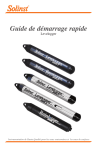
1
LOBO System Operation Manual Document Number: Revision: Date: SAT-DN-00434 B 2011-11-24 Satlantic Inc. 3481 North Marginal Road Halifax, Nova Scotia, Canada B3K 5X8 +1 902 492 4780 (tel) +1 902 492 4781 (fax) [email protected] http://www.satlantic.com COPYRIGHT Copyright © 2007, Satlantic Inc., 3481 North Marginal Road, Halifax, Nova Scotia B3K 5X8 Canada All rights reserved System Operation Manual LOBO SAT-DN-00434, Rev. B 2011-11-24 Page 2 of 85 Revision History Revision Description A Initial Release B Added SUNA information. Added Cycle PO4 information. Added Contact page. Added Warranty page. Updated GPRS modem data. Various operation details updated. Date June 8, 2007 November 24, 2011 Copyright 2011 Satlantic Inc. All rights reserved. Editor S.K. Feener, P.Eng. S.K. Feener, P.Eng. System Operation Manual LOBO SAT-DN-00434, Rev. B 2011-11-24 Page 3 of 85 Table of Contents 1 2 3 4 5 6 7 Introduction ..........................................................................................................................7 1.1 Purpose of this Manual..................................................................................................7 1.2 Document Overview ......................................................................................................7 1.3 Background...................................................................................................................7 1.4 Definitions, Acronyms and Abbreviations .......................................................................8 1.5 Referenced Documents.................................................................................................8 1.6 Quick Start Guide ..........................................................................................................8 1.6.1 Scheduled Operation Quick Start............................................................................9 Description of LOBO...........................................................................................................10 2.1 System Overview ........................................................................................................10 2.2 LOBO Configurations ..................................................................................................10 2.2.1 RiverLOBO...........................................................................................................11 2.2.2 DockLOBO...........................................................................................................13 2.2.3 BenthicLOBO .......................................................................................................15 2.2.4 BayLOBO.............................................................................................................16 Safety.................................................................................................................................17 3.1 Personal Safety...........................................................................................................17 3.1.1 Flooded Instrument...............................................................................................17 3.1.2 Cables..................................................................................................................17 3.1.3 Electricity..............................................................................................................17 3.2 Equipment Safety........................................................................................................17 3.2.1 Instruments ..........................................................................................................17 3.2.2 Connections .........................................................................................................17 3.2.3 Recovery..............................................................................................................17 Instrumentation ..................................................................................................................18 4.1 Satlantic STOR-X Datalogger/Controller ......................................................................18 4.2 Nortek Acoustic Sensors .............................................................................................20 4.2.1 Continental Profiler...............................................................................................20 4.2.2 Aquadopp Profiler.................................................................................................21 4.3 Satlantic Nitrate Sensors .............................................................................................22 4.3.1 Satlantic ISUS/ISUS-X..........................................................................................22 4.3.2 Satlantic SUNA.....................................................................................................24 4.4 WET Labs Sensors .....................................................................................................25 4.4.1 WET Labs ECO-CDS ...........................................................................................25 4.5 WET Labs ECO-FLNTUS ............................................................................................26 4.5.1 WET Labs WQM ..................................................................................................26 4.5.2 WET Labs Cycle Phosphate Sensor .....................................................................27 4.6 Sea-Bird SBE 37-SIP ..................................................................................................29 4.7 Aanderaa 3835 Oxygen Optode ..................................................................................30 Power System ....................................................................................................................32 5.1 Alkaline Battery Pack...................................................................................................32 5.2 Shore-Based Power System........................................................................................33 5.2.1 Solar Panel...........................................................................................................33 5.2.2 Battery Enclosure .................................................................................................35 Wireless Telemetry System ................................................................................................40 6.1 External Antenna and Antenna Cable ..........................................................................41 6.2 Cellular Modem ...........................................................................................................42 6.2.1 Modem Enclosure ................................................................................................42 6.3 A Note About Cellular Coverage ..................................................................................45 Server Computer................................................................................................................46 7.1 Server specifications ...................................................................................................46 7.2 Server IP Configuration ...............................................................................................46 7.3 Server Functions .........................................................................................................46 7.3.1 Overview..............................................................................................................46 Copyright 2011 Satlantic Inc. All rights reserved. System Operation Manual LOBO SAT-DN-00434, Rev. B 2011-11-24 Page 4 of 85 7.3.2 STOR-X Email Format..........................................................................................47 7.3.3 Web Server Interface............................................................................................48 8 Event Scheduling ...............................................................................................................55 8.1 Schedule File Format ..................................................................................................55 8.1.1 Schedule File Generator Utility .............................................................................55 8.2 Power and Data Size Considerations...........................................................................61 9 Data Formats and Data Extraction......................................................................................62 9.1 Using SatCon to Extract Data ......................................................................................62 10 System Startup and Operation ........................................................................................69 10.1 Prerequisites............................................................................................................69 10.1.1 Server Computer Prerequisites.............................................................................69 10.1.2 Cellular Telemetry Prerequisites ...........................................................................69 10.2 Startup Procedure....................................................................................................69 10.2.1 Step 1: Prepare Power System.............................................................................70 10.2.2 Step 2: Test STOR-X Communications.................................................................70 10.2.3 Step 3: Test STOR-X Ports (SUNA example)........................................................70 10.2.4 Step 7: Configure the STOR-X Cellular Parameters..............................................71 10.2.5 Step 8: Test the Cellular Modem Hardware...........................................................71 10.2.6 Step 9: Check and Set the Clock ..........................................................................71 10.2.7 Step 10: Enable the STOR-X Autorun Mode .........................................................71 10.2.8 Step 10: Start LOBO.............................................................................................72 11 Maintenance ...................................................................................................................73 11.1 Satlantic STOR-X Maintenance................................................................................73 11.2 Satlantic SUNA/ISUS/ISUS-X ..................................................................................73 11.3 Satlantic Alkaline Battery Pack Maintenance ............................................................74 11.4 WET Labs WQM Maintenance .................................................................................74 11.4.1 Replacing the WQM Bleach (when plumbed with ISUS only) ................................75 11.4.2 Purging the WQM of Bleach (when plumbed with ISUS only) ................................76 11.5 WET Labs Cycle PO4 Maintenance ..........................................................................78 11.6 Nortek Aquadopp Maintenance ................................................................................78 11.7 Nortek Continental Maintenance ..............................................................................78 11.8 WET Labs ECO-FLNTUS Maintenance....................................................................78 11.9 Seabird SBE-37SIP Maintenance.............................................................................79 11.10 Aanderaa Oxygen Optode Maintenance...................................................................79 11.11 Solar Panel Maintenance .........................................................................................79 11.12 Battery Box Maintenance .........................................................................................79 11.13 Wireless System Maintenance .................................................................................80 12 Warranty.........................................................................................................................81 13 Contact Information.........................................................................................................82 Copyright 2011 Satlantic Inc. All rights reserved. System Operation Manual LOBO SAT-DN-00434, Rev. B 2011-11-24 Page 5 of 85 Index of Tables Table 1: Example 2D Continental Specifications........................................................................20 Table 2: Example Aquadopp Specifications ...............................................................................21 Table 3: Example ECO-CDS Specifications...............................................................................25 Table 4: Example ECO-FLNTUS Specifications.........................................................................26 Table 5: Example WQM Specifications ......................................................................................27 Table 6: Example Cycle PO4 Specifications ...............................................................................28 Table 7: SBE 37-SIP Specifications...........................................................................................30 Table 8: Oxygen Optode 3835 Specifications ............................................................................30 Table 9: Standard Alkaline Battery Pack Specifications..............................................................32 Table 10: Solar Panel Specifications..........................................................................................33 Table 11: Panel Rack Specifications..........................................................................................34 Table 12: Battery Enclosure Specifications ................................................................................36 Table 13: Battery Specifications ................................................................................................37 Table 14: CLC Specifications.....................................................................................................38 Table 15: Lightning Arrestor Specifications ................................................................................39 Table 16: Antenna and Cable Specifications..............................................................................41 Table 17: GSM/GPRS Modem Specifications ............................................................................42 Table 18: Modem Enclosure Pin Configuration ..........................................................................44 Copyright 2011 Satlantic Inc. All rights reserved. System Operation Manual LOBO SAT-DN-00434, Rev. B 2011-11-24 Page 6 of 85 Index of Illustrations Figure 1: RiverLOBO.................................................................................................................11 Figure 2: RiverLOBO (dimensioned)..........................................................................................12 Figure 3: Typical DockLOBO Deployment..................................................................................13 Figure 4: DockLOBO (Dimensioned)..........................................................................................14 Figure 5: Typical BenthicLOBO Deployment ..............................................................................15 Figure 6: BayLOBO ...................................................................................................................16 Figure 7: Typical DockLOBO Sensor Configuration....................................................................18 Figure 8: STOR-X mounted in frame..........................................................................................19 Figure 9: Aquadopp mounted in RiverLOBO ..............................................................................21 Figure 10: ISUS in LOBO frame ................................................................................................22 Figure 11: ISUS/WQM plumbing................................................................................................23 Figure 12: SUNA and Hydro-Wiper mounted in LOBO ...............................................................24 Figure 13: SUNA and Hydro-Wiper............................................................................................24 Figure 14: WET Labs ECO-CDS CDOM Sensor in LOBO frame................................................25 Figure 15: WQM in LOBO Frame...............................................................................................27 Figure 16: WET Labs Cycle PO4 sensor mounted on LOBO......................................................28 Figure 17: Alkaline Battery Pack in LOBO frame........................................................................32 Figure 18: Shore-Based Power System .....................................................................................33 Figure 19: 80 Watt Solar Panel..................................................................................................34 Figure 20: Solar Panel Mounting Rack.......................................................................................35 Figure 21: IL2F Cable Face View...............................................................................................35 Figure 22: Battery Enclosure .....................................................................................................36 Figure 23: Battery Enclosure Connectors...................................................................................36 Figure 24: Battery Enclosure internal assembly .........................................................................37 Figure 25: Lightning Arrestor .....................................................................................................38 Figure 26: Wireless Telemetry System Components..................................................................40 Figure 27: RiverLOBO Modem Assembly ..................................................................................41 Figure 28: External Marine Antenna ..........................................................................................42 Figure 29: Modem Enclosure.....................................................................................................43 Figure 30: Modem Enclosure with Surge Protection...................................................................44 Figure 31: MCBH6M Bulkhead Face View .................................................................................44 Figure 32: STOR-X Email Format ..............................................................................................47 Figure 33: Main Web Page ........................................................................................................49 Figure 34: LOBOviz...................................................................................................................50 Figure 35: LOBOviz time series plot ..........................................................................................51 Figure 36: Archived raw data.....................................................................................................52 Figure 37: Schedule and previous schedule folders ...................................................................53 Copyright 2011 Satlantic Inc. All rights reserved. System Operation Manual LOBO SAT-DN-00434, Rev. B 2011-11-24 Page 7 of 85 1 Introduction 1.1 Purpose of this Manual This manual describes the capabilities, configuration, operating procedures and maintenance requirements of the Land/Ocean Biogeochemical Observatory (LOBO) water quality monitoring system. As LOBO is a system of components, this manual should be used in conjunction with the appropriate instrumentation user manuals. The intended audience for this manual includes operations personnel, system maintenance and design personnel, and technical authorities. 1.2 Document Overview Section 1 describes the purpose and overview of this document, background information, and includes a list of definitions, acronyms and abbreviations, and a list of references. Additionally, quick start instructions are provided to get the system functioning quickly. Section 2 familiarizes the user with the LOBO system and the various available configurations. Section 3 describes some hazards encountered in the operation of oceanographic instruments and recommends safe practices for the protection of personnel and equipment. Section 4 describes the instrumentation and sensors commonly found in a LOBO system. Section 5 describes the power system components used with LOBO. Section 6 describes the wireless telemetry system components. Section 7 provides a brief overview of the server computer used to receive, process, and archive data received from LOBO. Section 8 describes event scheduling, including the schedule file format and the schedule file generator utility. Power and data considerations are also discussed. Section 9 briefly discusses data formats and data extraction. Section 10 discusses initial startup of the LOBO hardware. Section 11 describes maintenance requirements. 1.3 Background The LOBO is a fully integrated, portable, real-time water quality monitoring system that addresses the need for routine, robust and accurate water quality measurements in sensitive and diverse ecological areas such as estuaries and inland waters. Near real time and archived data from Satlantic’s RiverLOBO deployed in the Northwest Arm in Halifax, Nova Scotia, can be viewed at http://lobo.satlantic.com. This site also contains links to other LOBO systems deployed in various locations including the Columbia River and Yaquina Bay in Oregon, the Penobscot River in Maine, and multiple sites in the Caloosahatchee River and estuary in Florida. Originally developed by Dr. Ken Johnson’s team at MBARI, LOBO is designed to create a near real time sensor network for aquatic systems. LOBO uses a system of high quality, high temporal resolution in-situ sensors to monitor fluxes. Water properties such as salinity and temperature are combined with nutrient measurements to monitor important processes that affect biogeochemistry. Copyright 2011 Satlantic Inc. All rights reserved. System Operation Manual LOBO SAT-DN-00434, Rev. B 2011-11-24 Page 8 of 85 LOBO has been extensively tested in a wide range of extreme water quality conditions since 2003 with a network of five systems in the Elkhorn Slough National Estuarine Research Reserve. Online real-time an archived data is available at http://www.mbari.org/lobo/loboviz.htm. The system addresses specific resource management concerns such as degraded coastal water quality, loss and alteration of estuarine watershed habitat, habitat restoration, reduction of biodiversity, and problematic effects of pollution and invasive species. The ability to study the interactions of the hydrologic and nutrient chemical cycles and human alterations of these cycles at the land/ocean interface is a fundamental component of coastal zone management, and one that has traditionally been a major scientific challenge. 1.4 Definitions, Acronyms and Abbreviations AGM Ah APN BLIS CLC DIW DNS GPRS GSM ICD IP LOBO NEMA NTP RTC SDD SIM TDF WQM 1.5 RD1. RD2. RD3. RD4. RD5. RD6. RD7. 1.6 Absorbed Glass Mat Amp-hours Access Point Name Bleach Injection System Charge and Load Controller De-Ionized Water Domain Name Server General Packet Radio Service Global System for Mobile Communications Interface Control Document Internet Protocol Land/Ocean Biogeochemical Observatory National Electrical Manufacturer’s Association Network Time Protocol Real Time Clock System Design Description Subscriber Identity Module Telemetry Definition File Water Quality Monitor Referenced Documents STOR-X Operation Manual, Satlantic Inc., SAT-DN-00242, Rev. E, 2011-06-07 Satlantic Instrument File Standard, Satlantic Inc., SAT-DN-00134, Version 6.1, 2010-0204 Satlantic Log File Standard, Satlantic Inc., SAT-DN-00135, Version 1.1, 2007-08-30 Technical Note, ISUS V2 Sampling Tips, Satlantic Inc.,, Aquadopp Current Profiler User Guide, Nortek AS, N3009-103, Revision B, September 2005 Continental Current Profiler User Guide, Nortek AS,, Rev C, October 2004 TD 218 Operating Manual – Oxygen Optodes, Aanderaa Data Instruments,,13th Edition, November 2005 Quick Start Guide This section provides a quick start to using the LOBO with references to detailed operating instructions found elsewhere. Please verify the contents of all shipping cases against the packing list. Copyright 2011 Satlantic Inc. All rights reserved. System Operation Manual LOBO SAT-DN-00434, Rev. B 2011-11-24 Page 9 of 85 LOBO is based around Satlantic’s STOR-X data logger and controller. The basic quick start instructions provided in its user manual (RD1) also hold true for LOBO, with some changes to account for hardware differences. Although LOBO can be used in a real-time mode, it is not a common use for the LOBO system. Please refer to the STOR-X manual for more information on this mode. 1.6.1 Scheduled Operation Quick Start 1. Connect the 6-pin download/programming cable to the STOR-X and to your computer. Start HyperTerminal (or another terminal emulator) at 57600 bps, 8N1, with no flow control. Please note that the STOR-X normally communicates at 9600 baud, but for ease of use in the various operating modes a baud rate of 57600 has been selected as the default. 2. Ensure the safety plug is reinstalled in the battery pack (if present) so it does not flood when deployed. 3. Apply power by connecting the battery cable to the STOR-X and battery pack. 4. You should see a startup message followed by the PicoDOS C:\ prompt in HyperTerminal. Press Enter to ensure the STOR-X is responding. 5. Verify the supply voltage by typing supply and then Enter. For the standard 15 V alkaline battery pack, the voltage should be higher than 15 V when new. 6. Check the current time held by the STOR-X’s precision real time clock using the clock get command. If the time is incorrect, set the time as described in the STOR-X manual. It is best to use UTC time. 7. Type config to verify instrument settings. Verify the instrument port settings and cellular settings. Modify if required. 8. Set the STOR-X to autorun in scheduled mode. This is found in the user settings menu of the config program. 9. Exit the program. The STOR-X should reboot and run the storxv2 program automatically. Observe the program step through the schedule file, stopping at the next event that will occur based on the current time. 10. Prepare for deployment: disconnect the programming/download cable from the STOR-X and install the dummy plug on the programming/download port. If you are not going to deploy immediately, remove the power cable so that the instruments do not power up in air – this will damage the Sea-Bird pump in the WQM, for example. Reconnect the power cable immediately before deployment. When terminating deployment: 1. If you are just maintaining the system (battery changes, cleaning, etc) simply disconnect the battery cable. Reconnect the battery cable immediately before redeploying. Or 2. Connect the STOR-X to a computer using the programming/download cable and establish communication using HyperTerminal. In the terminal window, press any key; when asked if you wish to end deployment, type y(es). 3. Check for STOR-X clock drift. At the prompt, use the clock get command to retrieve the current system time. Record this along with the UTC time from another reliable source in your deployment notes. Copyright 2011 Satlantic Inc. All rights reserved. System Operation Manual LOBO SAT-DN-00434, Rev. B 2011-11-24 Page 10 of 85 2 Description of LOBO 2.1 System Overview LOBO is a system of hardware and software components that integrates the autonomous remote control, storage and transmission of telemetry from a diverse set of oceanographic sensors. A typical system consists of one or more LOBO platforms each complete with a battery-based power system and cellular telemetry system, and a remotely located server computer running an email server to receive and store transmitted data and a web server that the platforms check for new acquisition schedules. Additionally, the server may run an instance of LOBOviz, a data visualization and display package for the entire network of monitoring sites. This powerful tool allows users to access and view real time or archived data, comparing multiple sensors at a site or multiple sites simultaneously though a simple web interface. This gives system users rapid and easy access to the monitoring network to help make informed decisions. A new live demonstration system has been deployed in Halifax Harbour, Canada (see http://lobo.satlantic.com for near real time and archived data). 2.2 LOBO Configurations The LOBO system is available in a variety of robust, easy to use platforms, depending on the deployment site conditions and user needs. Two floating platform configurations are available, one for waters as shallow as 1 meter (RiverLOBO), and one for deeper waters (BayLOBO). Both are designed for deployment with a minimum of effort in small boats. Users can easily move platforms around study sites to monitor critical locations. Each uses a modular instrument bay with quick release sensor modules for easy maintenance. A minimum of exposed infrastructure and a robust flotation system make the systems resistant to vandalism, and an optional independent GPS tracking system is available. LOBO platforms are also available for attaching to fixed structures such as docks or pilings (DockLOBO), or for placing directly on the bottom (BenthicLOBO). The various configurations are described in the following sections. Copyright 2011 Satlantic Inc. All rights reserved. System Operation Manual LOBO SAT-DN-00434, Rev. B 2011-11-24 Page 11 of 85 2.2.1 RiverLOBO Designed for rivers and estuaries with constant or periodic currents, the RiverLOBO utilizes a specially designed float to minimize drag. The robust system is designed to be temporarily submerged and has been tested in heavy icing conditions down to -20 C without missing any data transmissions. Data is transmitted back to the user via wireless options, typically cellular. Marine Hazard Light Cellular Modem GPS Tracking Device (optional) Flotation Frame and Sensors Figure 1: RiverLOBO A dimensioned drawing of the standard RiverLOBO platform can be found on the following page. Copyright 2011 Satlantic Inc. All rights reserved. System Operation Manual LOBO SAT-DN-00434, Rev. B 2011-11-24 Page 12 of 85 Figure 2: RiverLOBO (dimensioned) Copyright 2011 Satlantic Inc. All rights reserved. System Operation Manual LOBO SAT-DN-00434, Rev. B 2011-11-24 Page 13 of 85 2.2.2 DockLOBO Without flotation, DockLOBO is a convenient module to monitor water quality from fixed platforms of opportunity such as a dock or piling. By placing the hardware on a solid structure, this system can utilize solar power for more aggressive data acquisition schedules and lower operational costs, or continue to use a more discrete submerged replaceable battery pack. From the dock site the data can be sent back to the user via cabled or wireless options, typically cellular. Cellular Antenna Solar Panel Battery Box and Cellular Modem Frame and Sensors Figure 3: Typical DockLOBO Deployment A dimensioned drawing of an example DockLOBO using a submersible battery pack can be found on the following page. Copyright 2011 Satlantic Inc. All rights reserved. System Operation Manual LOBO SAT-DN-00434, Rev. B 2011-11-24 Page 14 of 85 Figure 4: DockLOBO (Dimensioned) Copyright 2011 Satlantic Inc. All rights reserved. System Operation Manual LOBO SAT-DN-00434, Rev. B 2011-11-24 Page 15 of 85 2.2.3 BenthicLOBO BenthicLOBO also has no flotation and is designed in a frame suitable for deployment on the bottom near a dock. Instrument data is transmitted back to shore using an armoured cable. Power is provided by a shore based power system using solar panels and batteries. From the shore the data can be sent back to the user via wireless or cabled options, typically cellular. Cellular Antenna Solar Panel Battery Box Frame and Sensors Bottom Frame Figure 5: Typical BenthicLOBO Deployment Dimensions for the LOBO frame would normally be identical to that of the DockLOBO in Figure 4. Dimensions of the bottom frame will depend on the deployment site. Copyright 2011 Satlantic Inc. All rights reserved. System Operation Manual LOBO SAT-DN-00434, Rev. B 2011-11-24 Page 16 of 85 2.2.4 BayLOBO Designed for protected bays and small lakes, the BayLOBO uses a heavy duty disc shaped float well suited for riding waves. A larger payload bay allows for more battery capacity for longer deployments. Data is sent back to the user via wireless options, typically cellular. Marine Hazard Light Cellular Modem Flotation Frame and Sensors Figure 6: BayLOBO Copyright 2011 Satlantic Inc. All rights reserved. System Operation Manual LOBO SAT-DN-00434, Rev. B 2011-11-24 Page 17 of 85 3 Safety Satlantic equipment should be operated and maintained with extreme care only by personnel trained and knowledgeable in the use of oceanographic electronic equipment. 3.1 Personal Safety 3.1.1 Flooded Instrument Use EXTREME CAUTION handling any instrument suspected of being flooded. If the instrument leaked at depth it might be pressurized when recovered. Indications of a flooded instrument include short circuits between connectors or an extended gap between the end cap and housing. If an instrument is suspected of being flooded, disconnect its power source, place it in a safe location and contact Satlantic for further instructions. If the instrument cannot be safety stored away, the following steps may be taken to release the pressure to render the instrument safe. PROCEED AT YOUR OWN RISK. To depressurize the STOR-X or ISUS, slowly unscrew a port connector just enough to break the seal with the end cap, allowing trapped water to escape around the connector threads. Attempt to drain the instrument completely. Depressurized and drained, the sensor is safe for normal storage. 3.1.2 Cables When deploying LOBO, operators should remain aware of any attached mooring or telemetry cable to avoid becoming entangled. Any cable or line released from a ship can be dangerous. Keep a safe distance from the cable coil on deck when the instruments are being deployed. 3.1.3 Electricity Use care when handling, connecting and operating power supplies and batteries. A shorted power supply or battery can output high current, harming the operator and damaging equipment. While trouble-shooting with a multi-meter, take care not to short the probes. Shorts can damage equipment, create safety hazards, and blow internal fuses. 3.2 Equipment Safety 3.2.1 Instruments Do not leave instruments in direct sunlight when not in use. Surfaces heated by direct sunlight can easily increase the internal temperature of the instrument beyond its rating. Employ measures to protect instruments and cables from being fouled or overrun by the vessel. 3.2.2 Connections Handle electrical terminations carefully. They are not designed to withstand strain. Disconnect the cables from the components by pulling on the connector heads and not the cables or molded splices. Twisting or wiggling the connector while pulling will damage the connector pins. 3.2.3 Recovery Do not haul instruments in by their electrical cables, unless they are reinforced with mechanical strength members for the purpose. Hauling on electrical cables can cause damage to the instrument port connectors, cables, and splices. Copyright 2011 Satlantic Inc. All rights reserved. System Operation Manual LOBO SAT-DN-00434, Rev. B 2011-11-24 Page 18 of 85 4 Instrumentation While highly customizable with respect to instrumentation, Satlantic’s STOR-X data logger will always be present, as it controls all aspects of the LOBO platform operation. A common configuration for a LOBO platform is as follows: STOR-X Port 1 2 3 4 Name Manufacturer Description WQM ISUS or SUNA ECO-CDS Not Connected WET Labs Satlantic WET Labs - 5 Not Connected - POWER MODEM BATTERY GSM/GPRS CDMA Measures several key water quality parameters. Provides nitrate concentration measurement Provides CDOM measurement Free for additional sensor; normally provides switched battery voltage for power Free for additional sensor; normally provides regulated 13 V for power 15 V, 51 Ah Alkaline battery pack Cellular or Satlantic Satlantic An example of a DockLOBO or RiverLOBO system configured in this manner is shown below. Note cables and plumbing are not shown. Figure 7: Typical DockLOBO Sensor Configuration The following sections describe some of the typical instrumentation and sensors that can be found on a LOBO platform. This list is not exhaustive. All instrumentation described will not be on every system. Please refer to the appropriate user manual for complete details. 4.1 Satlantic STOR-X Datalogger/Controller The STOR-X is a compact, low-power data logger that provides scheduled data acquisition in remote field applications. It acquires and logs data from up to five instrument ports according to a Copyright 2011 Satlantic Inc. All rights reserved. System Operation Manual LOBO SAT-DN-00434, Rev. B 2011-11-24 Page 19 of 85 user specified sampling schedule, entering a low power deep-sleep mode between events to conserve power to allow deployments for extended periods. All recorded data is date and time stamped from the STOR-X’s precision onboard real-time clock (RTC) to allow post-processing software to correlate all attached sensor data in time, as well as correlation between each monitoring site. For systems using wireless telemetry, a dedicated serial port on the STOR-X interfaces to an external cellular modem (or other wireless interface). The modem is used to email recorded data and an activity record to the user or server computer. In addition the STOR-X uses the modem to download new schedule files from a specified location, typically a server computer. The STOR-X is shown below in Figure 8, mounted in a DockLOBO or RiverLOBO frame. STOR-X Mounting Bracket (x2) Figure 8: STOR-X mounted in frame The STOR-X features supply voltage monitoring with brownout protection to better support operation from rechargeable battery power sources. The supply voltage is monitored and if the preset lower voltage threshold is reached, the STOR-X suspends operation and sleeps for a fixed amount of time (1 hour) to allow the power source time to recharge. The STOR-X then checks the supply voltage; if the voltage has recovered to a level above the upper voltage threshold, normal operation resumes. If not, the STOR-X sleeps for 4 hours, and then rechecks the supply voltage. The process repeats in 4 hour intervals until the supply voltage has recovered. Note that although the upper and lower voltage thresholds are configurable, these are administration mode settings, and are set to match the power source. Normally the end-user will not be required to change these settings. Note that the STOR-X also has a hardware low-voltage detection circuit that will force the STOR-X to shut down gracefully if power is inadvertently removed. Provided the autorun feature of the STOR-X is enabled, the shell program will force the program to restart when power is restored. Normally, the STOR-X simply switches the input voltage to the instrument ports to power the attached sensors. However, the voltage ranges for all sensors in the system may not be compatible with the power source. For example, the WET Labs WQM requires a 12 – 18 Vdc source, while the STOR-X itself can safely operate over a 6 – 18 Vdc range. The typical power source in a RiverLOBO system is a 15 V alkaline battery pack; over the life of the pack, the Copyright 2011 Satlantic Inc. All rights reserved. System Operation Manual LOBO SAT-DN-00434, Rev. B 2011-11-24 Page 20 of 85 battery voltage will range from greater than 16 V to 10 V or less, and during high-power operation the voltage can sag even further. To accommodate these variations in supply voltage requirements, the LOBO STOR-X can be equipped with an internal DC-DC converter to provide a regulated voltage to the appropriate sensor ports. The configuration of the DC-DC configuration depends on the system requirements and LOBO platform. Normally, a high-efficiency 6 – 18 V input, 13 V output converter is used for systems operating from an alkaline battery pack (e.g. RiverLOBO), while a high-power 10 – 20 Vdc input, 13.6 V output converter is better suited for some DockLOBO configurations. Please refer to the appropriate documentation (such as a technical note) for configuring the STOR-X for use with a specific instrument. 4.2 Nortek Acoustic Sensors At the time of writing of this document, two types of Nortek current profilers have been integrated and tested with the LOBO platform, the Continental and Aquadopp. These sensors are described below. 4.2.1 Continental Profiler The Continental Profiler is a sensor manufactured by Nortek AS, used for water current profiling. The Continental uses the Doppler Effect to measure water current velocity by transmitting short pulses of sound, listening to their echo and measuring the change in frequency of the echo. The Continental is available in both 2-D and 3-D versions. The 2-D model is intended for profiling along a horizontal segment. Due to its longer measurement range and correspondingly higher power consumption, and larger size (as compared to the Aquadopp), the Continental is best suited for the DockLOBO or BenthicLOBO platforms. Example specifications from a 2-D Continental model can be seen in the table below. Please refer to the manufacturer’s documentation for complete specifications. Table 1: Example 2D Continental Specifications Manufacturer Model Input Voltage Transmit Power Operating Power Operating Temperature Acoustic Frequency Maximum Profiling Range Cell Size Number of Cells Velocity range Accuracy Max. Sampling Rate Ancillary sensors Serial Interface Dimensions (approx) Weight (in air) Nortek AS Continental 12 – 18 Vdc 2 W – 120 W 1 W + Transmit Power -5°C to +35°C 470 kHz 100-150 m 1 – 10 m 1 – 128 ±10 m/s 1% of measured value 1 Hz Temperature, compass, tilt, pressure RS-232 at 9600 bps (configurable) 8.5” high x 7.5” diameter 16.5 lbs (7.5 kg) Normally, Satlantic will provide an ICD or other documentation describing the as-shipped configuration of the Continental. The ICD includes a procedure for reconfiguration of the sensor if required. It is expected that the end-user will change the configuration to match the actual operating environment. Specifically, the number of measurement cells, the cell size, and the profile interval (essentially averaging duration) are all expected to change. Note that if the Copyright 2011 Satlantic Inc. All rights reserved. System Operation Manual LOBO SAT-DN-00434, Rev. B 2011-11-24 Page 21 of 85 number of cells is modified, the size of the data frame will change and the STOR-X configuration will have to be adjusted accordingly. 4.2.2 Aquadopp Profiler The Aquadopp Profiler is a sensor manufactured by Nortek AS, used for water current profiling. As with the Continental profiler, the Aquadopp uses the Doppler Effect to measure water current velocity by transmitting short pulses of sound, listening to their echo and measuring the change in frequency of the echo. The Aquadopp is available in several configurations, depending on the deployment conditions and desired measurements. For example, the Aquadopp normally used on the RiverLOBO platform is a 2 MHz right-angle model intended for shallow water applications. The Aquadopp can be seen mounted in RiverLOBO below in Figure 9, while Table 2 provides a summary of specifications. Please refer to the manufacturer’s documentation for complete specifications. Mounting Brackets (x2) Aquadopp Figure 9: Aquadopp mounted in RiverLOBO Table 2: Example Aquadopp Specifications Manufacturer Model Input Voltage Transmit Power Operating Power Operating Temperature Acoustic Frequency Maximum Profiling Range Cell Size Number of Cells Velocity range Accuracy Max. Sampling Rate Ancillary sensors Serial Interface Dimensions (approx) Weight (in air) Nortek AS Aquadopp 9 – 16 Vdc 0.3 – 20 W 0.2 – 1.5 W + Transmit Power -5°C to +35°C 2 MHz 4 – 10 m 0.1 – 2 m 1 – 128 ±10 m/s 1% of measured value ±0.5 cm/ 1 Hz Temperature, compass, tilt, pressure RS-232 at 9600 bps (configurable) 24.7” long x 2.95” diameter 5.3 lbs (2.4 kg) Normally, Satlantic will provide an ICD or other documentation configuration of the Aquadopp. It is expected that the end-user will match the actual operating environment. Specifically, the number of size, and the profile interval (essentially averaging duration) are all Copyright 2011 Satlantic Inc. All rights reserved. describing the as-shipped change the configuration to measurement cells, the cell expected to change. Note System Operation Manual LOBO SAT-DN-00434, Rev. B 2011-11-24 Page 22 of 85 that if the number of cells is modified, the size of the data frame will change and the STOR-X configuration will have to be adjusted accordingly. 4.3 Satlantic Nitrate Sensors Satlantic’s nitrate sensors use ultraviolet absorption spectroscopy to measure in situ dissolved chemical species. These sensors are chemical-free, solid-state instruments that offer easy, accurate, real-time, and continuous nitrate concentration measurements 4.3.1 Satlantic ISUS/ISUS-X The MBARI In Situ Ultraviolet Spectrophotometer (MBARI-ISUS, commonly referred to as the ISUS) provides researchers with data essential to the study of physical, chemical, and biological processes in coastal, estuarine and freshwater environments. A variation of the ISUS, the ISUS-X also allows integration of up to four serial (RS-232) sensors and two analog voltages, creating a very adaptable system. Depending on the instrument selection, a powerful water quality monitoring system can be created. ISUS Figure 10: ISUS in LOBO frame If the LOBO platform also contains a WET Labs WQM sensor, the ISUS will be plumbed to the outflow from the WQM sensor. This configuration takes advantage of the WQMs bleach injection system to help clean the ISUS probe and help prevent biofouling from occurring. A copper tube on the exhaust of the ISUS flow cell also discourages biological growth. An image of the plumbing system is shown below; note all mounting struts are not shown for clarity. Please note that the flow cell exhaust must be the highest point in the system to ensure that any air bubbles are able to be flushed from the system. Copyright 2011 Satlantic Inc. All rights reserved. System Operation Manual LOBO SAT-DN-00434, Rev. B 2011-11-24 Page 23 of 85 Copper tube (exhaust) Flow cell Black Tygon tubing WQM exhaust WQM intake Figure 11: ISUS/WQM plumbing The default ISUS telemetry format is comma-delimited ASCII data. This is not the most efficient telemetry format, but is user-friendly. When used in the LOBO system, the ISUS is normally configured to output data in a fixed-length binary format. This reduces the amount of data by a factor of 2 – 3x; this results in a significantly smaller data file that must be emailed, with corresponding decrease in overall power consumption. This is particularly important in LOBO systems that use an alkaline battery pack in order to extend the battery life as long as possible. If an ISUS-X sensor is used, the user has the option of integrating additional sensors in to the system. As stated above, the ISUS-X will accept up to 2 analog voltages and up to 4 RS-232 serial outputs. In this configuration, the ISUS-X merges the ancillary sensor data into a single serial stream, thereby only using a single port on the STOR-X. There are restrictions, however, as the STOR-X currently only understands how to capture a single telemetry “type” on a port. If the sensor outputs linefeed terminated ASCII data (not raw binary), then generally it will work, although high data rates and/or very large data frames could be problematic. The telemetry from the ISUS-X must also be in ASCII format. There is a corresponding negative impact on battery life due to the larger file sizes that must be transmitted. Please consult with Satlantic prior to attempting this approach, as there are changes that have to be made to the settings for the ISUSX and STOR-X. Examples of sensors that have been successfully integrated in this manner are: WET Labs ECO series (e.g. ECO-FLNTUS, ECO-CDS) Sea-Bird SBE-37SIP Aanderaa Oxygen Optode In addition, the STOR-X must be instructed during port configuration that the instrument attached is an ISUS/ISUS-X. This instructs the STOR-X to send a “stop” command to the ISUS/ISUS-X prior to power removal. This stop command instructs the ISUS/ISUS-X to turn off the lamp and prepare for shutdown, but more importantly it is necessary as it instructs the ISUS-X to prepare its sensor ports for shutdown, allowing it to send “stop” commands to attached instruments that require them prior to power removal. For example, the WET Labs ECO sensors requires a stop command to close the shutter. Copyright 2011 Satlantic Inc. All rights reserved. System Operation Manual LOBO SAT-DN-00434, Rev. B 2011-11-24 Page 24 of 85 4.3.2 Satlantic SUNA Based on the same technology developed for the Satlantic ISUS nitrate sensor, the SUNA provides researchers with real-time nitrate measurements essential to the study of physical, chemical, and biological processes in coastal and freshwater environments from an economical and compact package. In a standard LOBO system, the SUNA will also be provided with a custom Hydro-Wiper that cleans the measurement windows prior to each sampling event, limiting biological growth and sediment build-up. Figure 12 below shows a rendering of the SUNA and Hydro-Wiper mounted in a LOBO frame, while Figure 14 shows greater detail of the wiper assembly. Figure 12: SUNA and Hydro-Wiper mounted in LOBO LOBO mounting clamps Hydro-Wiper Hydro-Wiper brush SUNA Figure 13: SUNA and Hydro-Wiper The default SUNA telemetry format is comma-delimited ASCII data. This is not the most efficient telemetry format, but is user-friendly. When used in the LOBO system, the SUNA is normally configured to output data in a fixed-length binary format. This reduces the amount of data by a factor of 2 – 3x; this results in a significantly smaller data file that must be emailed, with corresponding decrease in overall power consumption. This is particularly important in LOBO systems that use an alkaline battery pack in order to extend the battery life as long as possible. Copyright 2011 Satlantic Inc. All rights reserved. System Operation Manual LOBO 4.4 SAT-DN-00434, Rev. B 2011-11-24 Page 25 of 85 WET Labs Sensors A variety of WET Labs underwater sensors have been integrated into the LOBO system, as described in the following sections. 4.4.1 WET Labs ECO-CDS The ECO-CDS is a sensor manufactured by WET Labs to measure relative CDOM concentrations by measuring the fluorescence in a sample volume of water. The sensor has an anti-fouling wiper that opens and cleans the optical window before every measurement. This sensor can be seen mounted in a LOBO frame below. Example specifications are summarized below in Table 3. ECO-CDS (CDOM) Figure 14: WET Labs ECO-CDS CDOM Sensor in LOBO frame Table 3: Example ECO-CDS Specifications Manufacturer Model Input Voltage Typical Input Current Optical (Fluorescence) Wavelength excitation Wavelength emission Sensitivity Range (typical) Linearity Operating Temperature Operating Depth Sampling rate Serial Interface Dimensions Weight (in air) Weight (in water) WET Labs ECO-CDS 7 – 15 Vdc 80 mA (140 mA with bio-wiper) 370 nm 460 nm 0.09 ppb 0.09 to 500 ppb 99% R2 0 – 30 °C 300 m To 8 Hz RS-232 at 19200 bps Ø2.5 in x 5.25 in (Ø6.3 cm x 13.3 cm) 1.1 lbs (0.5 kg) 0.19 lbs (0.08 kg) Generally speaking, no changes to the factory default settings for the ECO sensors are required, although the user may wish to adjust the sample rate if higher temporal resolution or longer averages are desirable. During port configuration, the STOR-X must be informed that an ECO-sensor is attached. This allows the STOR-X to send a “stop” command to the sensor so that the shutter will close prior to power removal. Copyright 2011 Satlantic Inc. All rights reserved. System Operation Manual LOBO 4.5 SAT-DN-00434, Rev. B 2011-11-24 Page 26 of 85 WET Labs ECO-FLNTUS The ECO-FLNTUS is a sensor manufactured by WET Labs to measure chlorophyll-A fluorescence and turbidity. The sensor has an anti-fouling wiper that opens and cleans the optical window before every measurement. Note that the ECO-FLNTUS is a standard component of the WET Labs WQM. Example specifications are summarized below in Table 4. Table 4: Example ECO-FLNTUS Specifications Manufacturer Model Input Voltage Typical Input Current Optical (Turbidity) Wavelength Sensitivity (min) Range (typical) Optical (Fluorescence) Wavelength excitation Wavelength emission Sensitivity Range (typical) Linearity Operating Temperature Operating Depth Sampling rate Serial Interface Dimensions Weight (in air) Weight (in water) WET Labs ECO-FLNTUS 7 – 15 Vdc 80 mA (100 mA with bio-wiper) 700 nm 0.01 NTU 0 – 25 NTU 470 nm 685 nm 0.02 µg/l 0.02 to 60 µg/l 99% R2 0 – 30 °C 300 m To 8 Hz RS-232 at 19200 bps Ø2.5 in x 5.25 in (Ø6.3 cm x 13.3 cm) 1.1 lbs (0.5 kg) 0.19 lbs (0.08 kg) Generally speaking, no change to the factory default settings for the ECO sensors are required, although the user may wish to adjust the sample rate if higher temporal resolution or longer averages are desirable. During port configuration, the STOR-X must be informed that an ECO-sensor is attached. This allows the STOR-X to send a “stop” command to the sensor so that the shutter will close prior to power removal. 4.5.1 WET Labs WQM The WQM is a sensor manufactured by WET Labs to measure several key water quality parameters in a single package, incorporating both WET Labs and Sea-Bird sensors. These measurements include temperature, conductivity and salinity, depth, dissolved oxygen, chlorophyll fluorescence, turbidity, and backscattering data. The WQM also integrates a bleach injection system to help prevent biofouling. The figure below shows the WQM mounted in the LOBO frame. Example specifications are given below in Table 5; please refer to the manufacturer’s documentation for complete specifications. Copyright 2011 Satlantic Inc. All rights reserved. System Operation Manual LOBO SAT-DN-00434, Rev. B 2011-11-24 Page 27 of 85 Figure 15: WQM in LOBO Frame Table 5: Example WQM Specifications Manufacturer Model Input Voltage Input Current Measurement Ranges: Conductivity Temperature Pressure Oxygen Fluorescence Turbidity Depth Rating Sample Rate Serial Interface Dimensions (approx) Weight (in air) Weight (in water) WET Labs WQM 12-18 Vdc 0.275 A (typical) 0 – 9 S/m -5° to +35°C 0 – 200 m (optional sensor) 0 – 200% mg/l 0 – 50 µg/l (typical) 0 – 25 NTU (typical) 200 m 1 Hz RS-232 at 19200 bps 56.8 x 15.2 x 15.2 cm 5.4 kg 1.8 kg Normally, if integrated by Satlantic, an ICD or other documentation describing the as-shipped configuration of the WQM, with a procedure for reconfiguration if required, will be provided. Generally, the WQM will be reconfigured to give consistent measurement units across systems. An important point to note is that the dissolved oxygen sensor can take a significant amount of time to stabilize, depending on the sample flow rate and the water temperature. This is accommodated by adjusting the STOR-X schedule file to turn on the WQM for an extended period prior to acquiring data. During port configuration, the STOR-X must be informed that a WQM sensor is attached. This allows the STOR-X to send a “stop” command to the sensor so that the ECO-FLNTUS shutter will close prior to power removal, and allow the WQM to perform a bleach injection. 4.5.2 WET Labs Cycle PO4 Sensor The Cycle PO4 is a sensor manufactured by WET Labs to measure dissolved phosphate. Figure 16 below shows the Cycle PO4 mounted to a Dock LOBO frame in its correct vertical orientation. Copyright 2011 Satlantic Inc. All rights reserved. System Operation Manual LOBO SAT-DN-00434, Rev. B 2011-11-24 Page 28 of 85 LOBO frame and sensors Cycle PO4 Figure 16: WET Labs Cycle PO4 sensor mounted on LOBO Example specifications for the Cycle PO4 are given below in Table 5; please refer to the manufacturer’s documentation for complete specifications. Table 6: Example Cycle PO4 Specifications Manufacturer Model Input Voltage Input Current Measurement Range: Depth Rating Sample Rate Serial Interface Dimensions (approx) Weight (in air) WET Labs CYCLE-PO4 9.5-18 Vdc 2 A max, 0.125 A average 0 – 10 µM nominal 200 m 2 per hour max RS-232 at 19200 bps 56(h) x 18(w) cm 6.8 kg 4.5.2.1 Cycle PO4 STOR-X Connector Wiring The Cycle PO4 requires constant power and an external control line to allow the STOR-X to control its sampling schedule. This is achieved by using custom wiring on the STOR-X Cycle sensor port (normally port 5), as shown below. MCBH6F 2 3 1 6 5 4 Female Face View Instrument Port Pin Signal 1 Ground/VBATTERY2 Cycle RS-232 Data Receive 3 Cycle Wake 4 VBATTERY+ 5 Cycle RS-232 Data Transmit 6 not connected Figure 17: Cycle STOR-X Sensor Port Pin Assignment Copyright 2011 Satlantic Inc. All rights reserved. System Operation Manual LOBO SAT-DN-00434, Rev. B 2011-11-24 Page 29 of 85 VBATTERY+ is directly connected to the STOR-X POWER connector (MCBH2M pin 1). Cycle Wake is switched port power from the STOR-X, and is used to wake up the Cycle from sleep so that it may take a sample. The cable connecting the STOR-X to the Cycle is a straight-through cable (pin 1 to pin 1, pin 2 to pin 2, etc). Do not confuse this cable with the other STOR-X sensor cables! 4.5.2.2 Schedule File Requirements Refer to Section 8 Event Scheduling for a description of the STOR-X schedule file. To control the Cycle PO4, the schedule file will contain events similar to the following (cycle on port 5): # Start Cycle sample 00:55:00 POWER +V +5 00:55:05 POWER -5 -V 01:01:00 POWER 01:02:01 ACQUIRE 01:03:04 POWER +V +1 +2 60 1 2 -2 -1 -V 01:05:00 POWER 01:05:11 ACQUIRE 01:05:34 POWER +V +3 20 3 -3 –V 01:07:00 SENDEMAIL 1 # Retrieve data from cycle 01:45:00 SAMPLE 5 Here, at 00:55:00, the STOR-X will switch power to the Cycle Wake line for 5 seconds, initiating a sampling sequence which will roughly coincide with the other sensors that are sampling at 01:02:01 and 01:05:11. At 01:45:00, the STOR-X is retrieving this sampling data from the Cycle. Note that the STOR-X extracts time stamp information from the Cycle data – it is very important that the STOR-X and Cycle clocks are synchronized. Please refer to Appendix A – WET Labs Cycle PO4 Configuration. 4.5.2.3 Cycle PO4 Configuration The Cycle PO4 has several operating modes. If not configured properly, it will not operate as expected with the LOBO/STOR-X system. Please refer to Appendix A – WET Labs Cycle PO4 Configuration. 4.6 Sea-Bird SBE 37-SIP The SBE 37-SIP MicroCAT is a sensor manufactured by Sea-Bird Electronics used to measure conductivity and temperature in water. The SBE 37-SIP has an integral pump to flush the conductivity cell prior to measurement. The sensor contains an anti-fouling device to extend deployment time. Integrated pressure sensors are also available. Example specifications are given below in Table 7; please refer to the manufacturer’s documentation for complete specifications. Use caution when testing a LOBO system with an integrated SBE 37-SIP. Running the pump dry will damage it. Copyright 2011 Satlantic Inc. All rights reserved. System Operation Manual LOBO SAT-DN-00434, Rev. B 2011-11-24 Page 30 of 85 Table 7: SBE 37-SIP Specifications Manufacturer Model Input Voltage Input Current Measurement Ranges: Conductivity Temperature Pressure Initial Accuracy: Conductivity Temperature Pressure Acquisition Time Serial Interface Dimensions (approx) Weight (in air) Weight (in water) Sea-Bird Electronics SBE 37-SIP 7 – 24 Vdc 0.5 A 0 – 7 S/m (0 – 70 mS/cm) -5° to +35°C 0 – 20 m 0.0003 S/m (0.003 mS/cm) 0.002°C 0.1% of full scale 0.66 seconds/sample minimum (programmable) RS-232 at 9600 bps 20.81” long x 2.65” diameter 9.2 lbs (excluding clamps) 6.2 lbs (excluding clamps) If integrated by Satlantic, an ICD or other documentation describing the as-shipped configuration of the SBE 37-SIP, with a procedure for reconfiguration if required, will be provided. 4.7 Aanderaa 3835 Oxygen Optode The Oxygen Optode 3835 is a sensor manufactured by Aanderaa used to measure absolute oxygen concentrations in water using optical methods. The operation of the optode is based on the luminescence quenching principle, with a fluorescent indicator embedded in a gas permeable foil. A black optical isolation coating protects the foil. Note that the orientation of the optode is not critical – the optode has no “field of view” that can view objects outside the foil. It may be desirable to add a copper mesh covering (such as a scouring pad) or metallic copper tape to the optode to extend the duration between cleanings. Be careful to avoid contact of dissimilar metals to prevent corrosion. Example specifications are summarized in Table 8. Table 8: Oxygen Optode 3835 Specifications Manufacturer Model Input Voltage Average Input Current Aanderaa Oxygen Optode 3835 +5 - +14 Vdc 80 mA/S +0.3 mA, where S is the sample interval in seconds Oxygen: Range Resolution Accuracy Settling Time (63%) Temperature: Range Resolution Accuracy Settling Time (63%) Operating Temperature Operating Depth Sampling rate 0 – 500 µM < 1µM < 8µM or 5%, whichever is greater < 25 seconds 0° to +36°C 0.01°C ±0.05°C < 10 seconds 0° - 40°C 0 – 300 m (984.3 ft) 1 second to 255 minutes Copyright 2011 Satlantic Inc. All rights reserved. System Operation Manual LOBO Serial Interface Dimensions Weight (in air) SAT-DN-00434, Rev. B 2011-11-24 Page 31 of 85 RS-232 at 9600 bps Ø36 x 86 mm (Ø1.42 x 3.39”) 120 g (4.23 oz) If integrated by Satlantic, an ICD or other documentation describing the as-shipped configuration of the SBE 37-SIP, with a procedure for reconfiguration if required, will be provided. Copyright 2011 Satlantic Inc. All rights reserved. System Operation Manual LOBO SAT-DN-00434, Rev. B 2011-11-24 Page 32 of 85 5 Power System There are two basic types of power systems available for the LOBO: Alkaline Battery Pack Shore-Based Power System The system used will depend on the deployment situation, and may be customized to suit the specific deployment requirements. The following sections describe each available system in more detail. 5.1 Alkaline Battery Pack The standard alkaline battery pack used by LOBO is a 15 V, 51 Ah submersible pack that is well suited for use with the RiverLOBO, BenthicLOBO, and BayLOBO platforms. An image of the battery pack can be seen in Figure 18 below, with a summary of specifications in Table 9. Alkaline Battery Pack Figure 18: Alkaline Battery Pack in LOBO frame Table 9: Standard Alkaline Battery Pack Specifications Manufacturer Model Nominal Pack Voltage Pack Capacity Cell Type Recommended Cell Manufacturer Number of Cells Cell Configuration Fusing Housing Material Operating Depth Dimensions Weight (in air) Weight (in water) Satlantic 15 V 51 Ah 15 V 51 Ah (depends on discharge rate and usage conditions of the end application) Alkaline D-cell Panasonic Industrial Alkaline or equivalent 30 3 parallel sets of 10 series cells, diode protected 3x slow blow 1.5A, 1x fast blow 4A, 3AG type Anodized 6061 Aluminum 1000 meters 19.4” long x 4.5” diameter 18.7 lbs 6.7 lbs Copyright 2011 Satlantic Inc. All rights reserved. System Operation Manual LOBO 5.2 SAT-DN-00434, Rev. B 2011-11-24 Page 33 of 85 Shore-Based Power System Shore-based power systems normally consist of a solar panel and rechargeable battery, although other power sources could be used. This type of power system is designed for DockLOBO and BenthicLOBO applications. The large battery allows for higher-power instruments to be used, as well as more aggressive acquisition schedules. The standard shore-based power system consists of an 80-Watt solar panel and vented battery enclosure, with a 3-meter long interconnect cable. These components are described in more detail in the following sections. A diagram of the power system is shown below in Figure 19. 80-Watt Solar Panel Panel Mounting Rack Battery Enclosure Figure 19: Shore-Based Power System 5.2.1 Solar Panel The specifications for the solar panel used in the power system are summarized below in Table 10. Table 10: Solar Panel Specifications Manufacturer Model Typical Power Voltage at typical power Current at typical power Dimensions Weight Carmanah CTI-80 80 W 17.2 V 4.66 A 47.76”x21.54”x0.79” 20 lbs ?? Copyright 2011 Satlantic Inc. All rights reserved. System Operation Manual LOBO SAT-DN-00434, Rev. B 2011-11-24 Page 34 of 85 The solar panel is shown below in Figure 20. Mounting Rack Solar Panel 3 meter Power Cable Figure 20: 80 Watt Solar Panel 5.2.1.1 Panel Mounting Rack An adjustable side-of-the-pole rack is provided for mounting the solar panel. Specifications for the rack are summarized below in Table 11. The rack is intended for mounting on a 2 ½” Schedule-40 pole using two U-bolts (included), although the design of the rack easily adapts to larger poles if necessary. The end-user must assemble the rack prior to (or during) deployment; instructions are provided with the rack. The assembled rack mounted on the panel is shown below in Figure 21; note the locations of the mounting clips (circled). Table 11: Panel Rack Specifications Manufacturer Model Rail Length Channel Length Weight Mounting Panel Angle Unirac 400103 24” 32” 6 lbs 2 ½” Schedule-40 pole Adjustable Copyright 2011 Satlantic Inc. All rights reserved. System Operation Manual LOBO SAT-DN-00434, Rev. B 2011-11-24 Page 35 of 85 Clips inside rail Mounting U-Bolts Clips outside rail Figure 21: Solar Panel Mounting Rack 5.2.1.2 Solar Panel Power Cable The solar panel is connected to the battery enclosure using a 3-meter long power cable, including a wet-pluggable connector, shown above in Figure 20 and Figure 21. The cable is attached to the solar panel’s wiring junction box. The pinout for the connector, an IL2F manufactured by Subconn, is provided below in Figure 22. PANEL + 1 2 PANEL - Figure 22: IL2F Cable Face View 5.2.1.3 Panel Orientation Guidelines In the Northern Hemisphere, the solar panel should face true south. For optimum performance the solar panel should be perpendicular to the sun at all times of the day, generally not possible without a sun-tracking mechanism. Tracking mechanisms are only efficient for large arrays. Time-of-day variations generally only account for a few percent variation in power output; local weather conditions have a much greater effect. However, there are also seasonal variations to consider – in the winter the sun is not at the same angle as in the summer. The user may choose to adjust the panel angle with the season, or pick a single angle for year round use. A general guideline is to set the panel angle (measured from horizontal) equal to the deployment locations latitude. 5.2.2 Battery Enclosure The Battery Enclosure is a vented, insulated aluminum box with a white powder coat finish, with stainless steel hinges and lockable hasp. The enclosure contains a large rechargeable battery, a charge and load controller (CLC), and associated fusing and wiring. Two bulkhead connectors on the top of the Battery Enclosure form the interface to the solar panel and the STOR-X. The Copyright 2011 Satlantic Inc. All rights reserved. System Operation Manual LOBO SAT-DN-00434, Rev. B 2011-11-24 Page 36 of 85 enclosure is intended to be mounted to a 2 ½” Schedule-40 pipe using two U-bolts (provided). A model of the Battery Enclosure is shown below in Figure 23. Mounting U-Bolt (x2) Female connector (To STOR-X) Male connector (From Solar Panel) Figure 23: Battery Enclosure A summary of specifications for the Battery Enclosure can be found below in Table 12. Table 12: Battery Enclosure Specifications Dimensions (internal) Dimensions (external) Total Weight (includes battery) Box Material Mounting Connectors Fuses 16”H x 16”W x 10”D 16.25”H x 16.25”W x 10.25”D (excluding connectors and mounting brackets) 60 lbs (approximate) Powder-coated aluminum 2 ½” Schedule-40 pole 2-pin male: BH2M (Subconn) 2-pin female: BH2F (Subconn) ABC-8 (quantity 2) The connector pinouts are shown below in Figure 24. BATTERY + PANEL - 2 1 PANEL + 1 2 BATTERY - BH2F Female Face View (to STOR-X) BH2M Male Face View (to Solar Panel) Figure 24: Battery Enclosure Connectors The internal assembly of the Battery Enclosure is shown below in Figure 25. Copyright 2011 Satlantic Inc. All rights reserved. System Operation Manual LOBO SAT-DN-00434, Rev. B 2011-11-24 Page 37 of 85 CLC Fuses (2x ABC-8) Battery Bracket 55 Ah AGM Battery Dummy Plugs (for bulkhead connectors) Figure 25: Battery Enclosure internal assembly The following two sections describe the battery and CLC in greater detail. 5.2.2.1 Rechargeable Battery The standard rechargeable battery used by the Power System is a maintenance-free Absorbed Glass Mat (AGM), 12 V, 55 Ah battery designed specifically for solar panel applications. The battery specifications are summarized below in Table 13. Table 13: Battery Specifications Manufacturer Model Voltage Capacity Type Weight Dimensions Discharge cycles Soltek powersource Extreme EX-580 12 V 55 Ah AGM 38 lbs 9” x 6” x 9” 600+ cycles to 50% Copyright 2011 Satlantic Inc. All rights reserved. System Operation Manual LOBO SAT-DN-00434, Rev. B 2011-11-24 Page 38 of 85 5.2.2.2 Charge and Load Controller The Charge and Load Controller (CLC) used by the Power System is a Sunsaver-6L, manufactured by Morningstar Corporation. The purpose of the CLC is safe and efficient charging of the AGM battery, and to protect the battery from deep discharge by disconnecting the load if the battery discharges below a threshold voltage. The CLC is temperature compensated to provide optimal charging of the battery over all operating conditions. The CLC specifications are summarized below in Table 14. Table 14: CLC Specifications Manufacturer Model Voltage Rated Solar Input Rated Load Regulation Voltage Temperature Compensation Load Disconnect Load Reconnect Operating Temperature Dimensions Weight Morningstar Corporation Sunsaver-6L 12 V 6.5 A 6A 14.1 V nominal -28 mV/°C 11.5 V 12.6 V -40 to +85 °C 6” x 2.18” x 1.32” 8 oz. 5.2.2.3 Lightning Arrestor To help protect against surges caused by nearby lightning strikes, a DC surge arrestor can be provided. An image of the arrestor is shown below in Figure 26; please note that the Lightning Arrestor is not shown in the Figure 25 assembly. The arrestor is mounted inside the battery box, and is wired across the solar panel input connections of the CLC, with a third wire connected to chassis/earth ground. If the lightning-induced voltage exceeds a threshold level, the arrestor will start to conduct, effectively shorting the higher voltage to ground in order to protect the equipment. If the surge is sufficiently strong, the arrestor may be damaged and will require replacement. The arrestor specifications are summarized below in Table 15. Figure 26: Lightning Arrestor Copyright 2011 Satlantic Inc. All rights reserved. System Operation Manual LOBO SAT-DN-00434, Rev. B 2011-11-24 Page 39 of 85 Table 15: Lightning Arrestor Specifications Manufacturer Model Max Voltage to ground Surge Current Wire Leads Dimensions Delta LA-302DC 250 V 60 000 A 3x 18” #12AWG 2 ¼” long x 2 ¼” diameter Copyright 2011 Satlantic Inc. All rights reserved. System Operation Manual LOBO SAT-DN-00434, Rev. B 2011-11-24 Page 40 of 85 6 Wireless Telemetry System The Wireless Telemetry System for LOBO normally consists of a cellular modem (GPRS or CDMA) mounted in a NEMA 6P enclosure, an antenna and cable, and a power/communications interconnect cable to the STOR-X. The modem is used to transmit data recorded by the STOR-X to the end user or the server computer, and to download new schedule files from the server. Details of these components are provided in the following sections. The physical configuration of the wireless system will vary depending on the type of LOBO platform in use. For the DockLOBO and BenthicLOBO configurations, a large external marinegrade antenna is generally used, usually with 3 dB of gain to assist in areas with poor cellular signal strength. For the RiverLOBO and BayLOBO, a small whip antenna is usually mounted inside the modem enclosure to protect it from damage. A diagram of the wireless telemetry system components is shown below in Figure 27 for a typical DockLOBO or BenthicLOBO configuration. The inset image shows the relative height of the antenna. Antenna Antenna Cable GSM Modem Enclosure Cable to STOR-X Figure 27: Wireless Telemetry System Components A diagram of the cellular modem assembly for a typical RiverLOBO system is shown below in Figure 28, with the inset image illustrating the small internal antenna. Note there are several variations for the RiverLOBO modem assembly – your system may not be exactly as shown. Copyright 2011 Satlantic Inc. All rights reserved. System Operation Manual LOBO SAT-DN-00434, Rev. B 2011-11-24 Page 41 of 85 Cellular Modem Assembly Internal Antenna Figure 28: RiverLOBO Modem Assembly 6.1 External Antenna and Antenna Cable The Wireless Telemetry System uses a dual-band marine-grade cellular antenna, connected to the modem enclosure through a low-loss coaxial cable. The specifications are summarized in Table 16; the antenna is shown in Figure 29. Table 16: Antenna and Cable Specifications Manufacturer Model Frequency Gain Length Connector Extension Adapter Antenna Base Cable Type Cable Length Cable Connectors Shakespeare Galaxy 5412-P Dual Band 800-900 MHz and 1800-1900 MHz 3 dB 2 feet N female 4 ½” length, female to female, 1”-14 threads 3” diameter, 1”-14 thread Shakespeare Lo-Max® 5 meters (can be shortened) N-male (to antenna), TNC male (to modem enclosure) Copyright 2011 Satlantic Inc. All rights reserved. System Operation Manual LOBO SAT-DN-00434, Rev. B 2011-11-24 Page 42 of 85 Antenna Base 4 ½” Adapter 2’ Antenna Antenna Cable Figure 29: External Marine Antenna 6.2 Cellular Modem Data collected by the STOR-X on LOBO is transmitted to the end user or server computer using a cellular modem. Presently, only GPRS (GSM) modems are supported, although CDMA modems may be possible in special situations. Some of the relevant specifications for the GPRS version are summarized below in Table 17. Table 17: GSM/GPRS Modem Specifications Manufacturer Model Type Frequency Packet-Switched Data Internet Enabled Multi-Tech Systems Inc. MTCBA-G-F4 GSM/GPRS Quad Band 850/900/1800/1900 MHz GPRS Class 10 (up to 85 kbps) Embedded TCP/IP stack For the GSM/GPRS modem, the user will need to purchase a cellular data plan. The cellular service provider will supply a SIM card when the data plan is purchased. The SIM card must be installed in the modem, which may require the modem to be removed from its enclosure, depending on the model provided. Please refer to the STOR-X manual RD1 for instructions. 6.2.1 Modem Enclosure There are several versions of the modem enclosure available, depending on the LOBO platform used and the user requirements. The basic versions are RiverLOBO Modem Enclosure DockLOBO Modem Enclosure DockLOBO Modem Enclosure with Surge Protection 6.2.1.1 RiverLOBO Modem Enclosure This version of the modem enclosure has a NEMA 6P rating. Overall dimensions are 8.9" x 3.8" x 3.9", with four hidden mounting holes. The enclosure is mounted directly to the float retaining plate on RiverLOBO. Four screws hold the lid down; remove the lid to access the modem. Copyright 2011 Satlantic Inc. All rights reserved. System Operation Manual LOBO SAT-DN-00434, Rev. B 2011-11-24 Page 43 of 85 6.2.1.2 DockLOBO Modem Enclosure This version of the modem enclosure has a NEMA 6P rating. Overall dimensions are 7.5" x 5.4" x 4.8", with four 0.31" flanged mounting holes on 2” centers. The enclosure can not be mounted directly to a 2.5” pipe using U-bolts – an adapter of some sort will be required. An antenna connector and a power/communications bulkhead connector provide the electrical interface to the enclosure. The intent is to mount the enclosure with the connectors facing down, as shown above in Figure 27. The enclosure is also shown below in Figure 30. 7.5” MCBH6M Power/ Communications (To STOR-X) 5.4” Antenna Connector Figure 30: Modem Enclosure 6.2.1.3 DockLOBO Modem Enclosure with Surge Protection For areas that are prone to lightning strikes, the modem enclosure can include components to help protect against nearby lightning strikes. This version of the modem enclosure has a NEMA 6P rating. Overall dimensions are 11.6” x 9.4" x 4.3", with four flanged mounting holes. The lid is closed with a padlockable latch. A grounding stud, an antenna connector and a power/communications bulkhead connector provide the electrical interface to the enclosure. The intent is to mount the enclosure with the connectors facing down, as shown above in Figure 27. The enclosure is also shown below in Figure 31 with the GSM modem; the SIM card can be replaced without removing the modem. After installation, connect the grounding stud to earth ground using heavy guage copper wire or a copper grounding strap. Copyright 2011 Satlantic Inc. All rights reserved. System Operation Manual LOBO SAT-DN-00434, Rev. B 2011-11-24 Page 44 of 85 Padlockable Latch Grounding Stud Modem Data Line Surge Protector Coax Surge Protector Power Line Surge Protector Figure 31: Modem Enclosure with Surge Protection 6.2.1.4 Modem Enclosure Connector All versions of the Modem Enclosure have a common electrical interface to the STOR-X. The 6pin male bulkhead connector that serves as this interface is shown below in Figure 32. The connector pinout is provided in Table 18. 6 2 1 5 3 4 Figure 32: MCBH6M Bulkhead Face View Table 18: Modem Enclosure Pin Configuration Pin 1 2 Pin Name V+ V- Notes Power to Modem Power and Signal Ground Copyright 2011 Satlantic Inc. All rights reserved. System Operation Manual LOBO 3 4 5 6 6.3 CTS RTS RX TX SAT-DN-00434, Rev. B 2011-11-24 Page 45 of 85 Clear To Send from Modem Request To Send to Modem RS-232 Data from Modem RS-232 Data to Modem A Note About Cellular Coverage Please ensure that you have adequate cellular coverage (normally GPRS required) in the area in which you intend to deploy LOBO. Satlantic cannot be held responsible for systems that fail to transmit data due to lack of cellular coverage. Copyright 2011 Satlantic Inc. All rights reserved. System Operation Manual LOBO SAT-DN-00434, Rev. B 2011-11-24 Page 46 of 85 7 Server Computer Although LOBO transfers data via email, it requires that the email server to which it is connected have a static IP address; presently DNS is not supported. Furthermore, as the incoming email from LOBO can not be authenticated, it is generally viewed as spam by the email server, requiring that the email server be properly configured to accept the incoming email. This can be very problematic for some institutions due to security concerns. However, the system works well when set up with a dedicated server computer (or a hosted virtual machine) whose purpose is to receive and store emailed data from the LOBO platform(s), and to host new schedule files for LOBO to download. Furthermore, the server computer can run an instance of LOBOviz for near real-time processing and display of the received data for both researchers and the general public. For an example of LOBOviz, please see http://lobo.satlantic.com/ and http://lobo.satlantic.com/loboviz.shtml. With the present version of LOBOviz, Satlantic requires access to the server for configuration and testing of the system. 7.1 Server specifications Satlantic suggests the following basic specifications for the server: 1. Linux operating system (Scientific Linux if possible) 2. 1 GHz or better processor 3. 30 GB harddrive or larger, preferably in a RAID Level 1 configuration, preferably SCSI for reliability and long life 4. 512 MB RAM 5. 10/100 network card 6. Basic video card 7. Basic keyboard, monitor, mouse, etc If you are providing the server, please consult Satlantic to ensure that the hardware is suitable. An alternative and preferred solution is to use a hosting service and install the email server and LOBOviz on a virtual machine. Please contact Satlantic for details. 7.2 Server IP Configuration The server must have a static IP address. 7.3 Server Functions 7.3.1 Overview The Linux server runs two services; a mail server (Postfix) and a web server (Apache). The mail server accepts messages from the Internet with the intention of accepting only messages related to Satlantic instrumentation. An email message addressed to the data storage user ([email protected]) that contains a message header of "X-SatlanticInstrument:" is filtered by way of the procmail delivery agent into a holding directory. Scripts that run periodically scan the holding directory for messages and unpack the contents. The files created from that unpacking process are moved to a filesystem location that is served to the Internet via the web server. The files themselves are renamed to match the serial number of the instrument with the date and time of the message when the mail server delivered it. An additional numeric field in the file name is used to prevent clashes of two messages from the same instrument in the same second. Note that the instrument serial number can be found in the email X-Satlantic-Instrument header line. Copyright 2011 Satlantic Inc. All rights reserved. System Operation Manual LOBO SAT-DN-00434, Rev. B 2011-11-24 Page 47 of 85 Similarly, the server will accept instrument schedule files if the email contains a subject of "schedule update serial-number-value". The schedule file should be within a text attachment and must contain a string of "STOR-X SCHEDULE FILE". The message body is unimportant, but must not contain that same string. The unpacked schedule files are also made available via the web server and renamed to begin with the instrument serial number. The schedule file messages will only be accepted from a defined user list to help prevent unauthorized users from updating the schedule. The following sections first describe the received email format, and then describe the web server interface. 7.3.2 STOR-X Email Format The format of the email message received from the STOR-X is shown below in Figure 33 as a Thunderbird email utility screen capture and described in the following subsections. Descriptive subject line The STOR-X’s email address Custom X-Header STOR-X’s log (event) file contained in body of message LOBO data as attachment Figure 33: STOR-X Email Format 7.3.2.1 The Email Subject Line The subject line has the format “STOR-X sn XXXX Log File (filename.raw)”, where XXXX is the serial number of the STOR-X and filename is the name of the attached file. The subject line is created automatically by the STOR-X and is not configurable. Copyright 2011 Satlantic Inc. All rights reserved. System Operation Manual LOBO SAT-DN-00434, Rev. B 2011-11-24 Page 48 of 85 7.3.2.2 The Email To: Line The To: address is configurable in the STOR-X. However, for the as-shipped filters and scripts on the server to operate properly, the user name must be “lobodata”, e.g. [email protected], and not “[email protected]” as shown in Figure 33 above. This generic approach can work as LOBO connects directly with the server when sending the email. 7.3.2.3 The From: and Return-Path Lines The STOR-X’s email address is configurable in the STOR-X. Although not required for system operation, some networks may require that the return email address is valid for authentication so that the email is not rejected as spam. Please contact your cellular service provider if an email address is required. The server is also configured to only accept email from this user. 7.3.2.4 Custom X-header The email will contain a custom email X-header, of the format “X-Satlantic-Instrument: STOR-X sn XXXX”, where XXXX is the STOR-X serial number. 7.3.2.5 Email Body The email body contains the event log for the STOR-X. 7.3.2.6 Data Attachment The STOR-X data file is attached to the email message. Note that base-64 encoding is used on the data file prior to sending. 7.3.3 Web Server Interface The main web page will be located at the server’s IP address described previously. Note that it is important that the IP address remain static for the web interface to work properly. Generally, the web page will be customized, with both a public and private interface. Below, we use some of the private Satlantic interface as an example. Satlantic’s present main web page is shown below in Figure 34; your page will look significantly different. You may modify the web page as desired provided the data and schedule file locations do not change, as this would affect the server scripts as well as the STOR-X path settings. Copyright 2011 Satlantic Inc. All rights reserved. System Operation Manual LOBO SAT-DN-00434, Rev. B 2011-11-24 Page 49 of 85 Figure 34: Main Web Page Selecting the LOBOviz link takes you to the LOBOviz data display page, where recent and archived data can be accessed and displayed. Copyright 2011 Satlantic Inc. All rights reserved. System Operation Manual LOBO SAT-DN-00434, Rev. B 2011-11-24 Page 50 of 85 Figure 35: LOBOviz For example, if we plot a time series for nitrate concentration and fluorescence, we can see the spring bloom occurring, as shown below. Copyright 2011 Satlantic Inc. All rights reserved. System Operation Manual LOBO SAT-DN-00434, Rev. B 2011-11-24 Page 51 of 85 Figure 36: LOBOviz time series plot 7.3.3.1 Raw Archive Folder The private web interface will provide access to archived data as received from LOBO. Folders are organized by year, then month, then day. The server scripts process the raw email data into numbered .split files, based on the number of acquisition events found within the file; each .split file is a separate acquisition time. An example from Satlantic’s server is shown below in Figure 37. Please note that this data is not identical to that displayed by LOBOviz; this data is “raw”, meaning that it contains every frame for each sensor as recorded by the STOR-X for the event. This raw data can then be extracted (e.g. with SatCon) for more in-depth manual analysis if desired. LOBOviz performs processing on the raw data, including applying calibration coefficients, averaging, and quality checks on the data. Copyright 2011 Satlantic Inc. All rights reserved. System Operation Manual LOBO SAT-DN-00434, Rev. B 2011-11-24 Page 52 of 85 Figure 37: Archived raw data The “.raw” files are renamed using the format sn YYYY-MM-DD HH-MM-SS n filename.raw.splitx where the STOR-X’s serial number date file received time file received sequentially numbers, starting at 0, in case multiple files from the same STOR-X with the same time stamp are received the file received from the STOR-X sequentially numbered based on the number of acquisition events within a given received data file sn YYYY-MM-DD HH-MM-SS n filename.raw splitx Note that the file must be renamed because the STOR-X makes daily log files – each email received is data from that day since the last email. Additionally, each STOR-X uses the YYYYDDD.raw format, without serial number information, thus the serial number must be appended as all data files are in the same folder. Also note that the raw files will have both ASCII and binary data. There may also be another folder present in which the unprocessed email is archived. The STOR-X sends status messages in the body of the email; this information can be useful when debugging misbehaving systems or sensors. The status messages are in ASCII format and can be seen by simply opening the file in a text editor. 7.3.3.2 Schedule Folder The private web interface will also provide access to the LOBO schedule folder, shown below in Figure 38. Scripts running on the server will periodically check the received email for valid schedule update emails. If present, the new schedule will be extracted, renamed, and placed in the folder. Any existing schedule file for the selected STOR-X will be moved to the “previous” subfolder. Copyright 2011 Satlantic Inc. All rights reserved. System Operation Manual LOBO SAT-DN-00434, Rev. B 2011-11-24 Page 53 of 85 Figure 38: Schedule and previous schedule folders Schedule files are used by the STOR-X to schedule power, data acquisition, and email events. After transmitting their data, each STOR-X checks the schedule folder for its new schedule file, and retrieves it if available. If the file is not present, the STOR-X simply continues to use its existing schedule. Note that the STOR-X will continue to download the schedule file each time it checks, even if it has not changed. There is not a problem in doing so, although it will add to the Copyright 2011 Satlantic Inc. All rights reserved. System Operation Manual LOBO SAT-DN-00434, Rev. B 2011-11-24 Page 54 of 85 overall cellular data plan usage. The user may manually delete the schedule file after it has been downloaded by the STOR-X if they wish, but this is not required, as the schedule file will remain in the folder for normally 24-48 hours to ensure that the STOR-X has had time to download it, and then will be moved automatically to the previous folder. This is a simple but effective way to reduce the total amount of data transferred, as the STOR-X will download the schedule every time it connects if it is present – there is currently not a mechanism for the STOR-X to check if the schedule file has already been downloaded As explained previously, sending a properly configured email to the server will update the schedule file in the folder. For example, to update the schedule for STOR-X serial number 0022, send an email to the server with the subject “schedule update 0022” with a properly written schedule file named “schedule.txt”. The server will extract the schedule file and save it to the schedule folder with the STOR-X serial number prepended to the file name, e.g. “0022schedule.txt”. For a discussion regarding the format of the schedule file, please refer to Section 8 Event Scheduling. Copyright 2011 Satlantic Inc. All rights reserved. System Operation Manual LOBO SAT-DN-00434, Rev. B 2011-11-24 Page 55 of 85 8 Event Scheduling As described previously, the STOR-X is the central data logger and controller for LOBO. The STOR-X operates on a flexible, user-defined daily schedule. There are three basic types of events allowed: Power (on/off) Acquire Email data As required, support for new events or commands may be added to the STOR-X firmware to allow integration of new sensors. For example, the STOR-X uses the new “SAMPLE” event to retrieve the last data measurement point from the WET Labs Cycle PO4 sensor. The typical order of events is power on, acquire data for the scheduled amount of time, and then power off. Between power off and power on events, the STOR-X enters a low-power sleep mode in order to conserve battery life. Data may be emailed after each event, at periodic intervals, at arbitrary times throughout the day, or at the end of the day. A description of the email can be found in Section 7.3.2. The frequency and duration of acquisition events is dependent on user needs, storage capacity, and available power. The following sections discuss the schedule file format, a utility to assist in creating schedule files, and power and data considerations. 8.1 Schedule File Format Schedule files are used by the STOR-X to schedule power, data acquisition, and email events. The schedule file is a simple ASCII text file containing the daily events for the STOR-X. For the basic format of the schedule file, please refer to the STOR-X manual RD1. However, the server scripts used in the LOBO system requires special delimiter lines at the beginning and end of the file to allow the STOR-X to easily extract the schedule file after retrieving it from the server. The beginning of the file must contain the line ##### SCHEDULE FILE START while the end of the schedule file must have the line ##### SCHEDULE FILE END The lines must be exactly as shown. Anything before or after these lines will be ignored by the STOR-X when extracting the schedule file. Creating the schedule file manually is tedious and error prone, particularly when there are a large number of events to schedule. Therefore it is recommended to use the Schedule File Generator utility to create a baseline schedule, and edit it manually if necessary. The utility is described in the following section. 8.1.1 Schedule File Generator Utility The Schedule File Generator, more commonly known as the ISUSSchedule program, was originally created for use with the ISUS and ISUS-X, but it can also be used to generate STOR-X schedule files. The utility can also be used to verify the syntax of schedule files. This utility should have been included with the LOBO shipment. Note that only version 1.5.1 or later may be used with this system. Copyright 2011 Satlantic Inc. All rights reserved. System Operation Manual LOBO SAT-DN-00434, Rev. B 2011-11-24 Page 56 of 85 ISUSSchedule is presently only available as a MS-Windows application and so can not reside on the Linux server. It requires MS-Windows NT, 2000, or XP to run. The program is provided as a self-installing executable. In order to execute the program, the MatLab Component Runtime has to be installed. This component is present with all installations of MatLab 7 (R14). For users without a MatLab license, a stand-alone runtime must be installed. A simple manual is provided with the ISUSSchedule program, however a thorough procedure is provided below to generate a common schedule for a typical LOBO system. In this example, we have the following physical configuration: Port 1: WQM Port 2: ISUS Port 3: ECO-CDS Port 4: Unused Port 4: Unused We wish to optimize the schedule to maximize life of the battery pack while maintaining good temporal resolution. A once an hour schedule is acceptable. The WQM must be turned on early to ensure that the sampling volume is well flushed and to allow time for the dissolved oxygen sensor to stabilize; about 1 minute should suffice. Because the ISUS is plumbed with the WQM sensor, it should acquire data during the same time. One minute of acquisition time should be sufficient. To eliminate any chance of interference between the ECO-FLNTUS in the WQM and the separate ECO-CDS, the ECO-CDS power-up and acquisition will occur separately; 20 seconds of data for this sensor should suffice. Note that this example may seem quite a bit more complicated than a typical STOR-X schedule. However, these sensors have been extensively tested at Satlantic, and this schedule is highly optimized for performance. 1. Start the ISUSSchedule program. You will see a DOS window open, followed by the actual Windows application. 2. In the Instrument drop down list, select STOR-X as shown below. 3. As explained above, only Ports 1-3 and the modem port (don’t forget this!!) are required, so select these as shown below. Copyright 2011 Satlantic Inc. All rights reserved. System Operation Manual LOBO SAT-DN-00434, Rev. B 2011-11-24 Page 57 of 85 4. To configure the ports to acquire data once per hour, select the acquisition frequency as shown. We’ll set the Offset for 1 minute for the WQM and ISUS (ports 1 and 2) so that the events do not occur precisely on the start of the hour – this can cause problems on the midnight rollover. Note that we could also just manually edit the schedule file later so that the first event does not occur precisely at midnight. Set the Offset for the ECO-CDS (Port 3) to 5 minutes so that it turns on separately. Set the Wait for Ports 1 and 2 to 60 seconds to allow flushing and stabilization of the WQM as described; the ISUS also takes 30-45 seconds to start up. Finally, set the duration to 60 seconds for Ports 1 and 2 and 20 seconds for Port 3. 5. To get the Modem to transmit data after each data event, we will set it to a 1/hour frequency as well, but Offset by 7 minutes. This ensures that the data event is completed before the email attempt starts. Leave the Retry field as 1 to allow one reattempt in case the email connection fails. Copyright 2011 Satlantic Inc. All rights reserved. System Operation Manual LOBO SAT-DN-00434, Rev. B 2011-11-24 Page 58 of 85 6. Notice that we have not used the Turn Off or From and To fields. These fields allow ports to be disabled during certain times of the day. Normally, this would be used when optical sensors that use sunlight are attached to the ports, so that you do not acquire data through the night and waste power and acquire unnecessary data. 7. Press the Generate New File button to create the schedule file. A warning will appear instructing you that it will take some time to verify the file. Click OK. When requested, save the file as Schedule.txt in the desired location. The file MUST be named Schedule.txt. 8. After saving the file, a Matlab-like figure will appear, as shown below. This gives a graphic representation of how active each port is. The vertical axis represents each port, while the horizontal axis indicates the hour of the day. Close the figure when you are ready. 9. Exit the ISUSSchedule program. Copyright 2011 Satlantic Inc. All rights reserved. System Operation Manual LOBO SAT-DN-00434, Rev. B 2011-11-24 Page 59 of 85 10. Browse to the folder containing the schedule file and open it in a text editor such as Windows NotePad. You will see the following: ##### SCHEDULE FILE START # # STOR-X SCHEDULE FILE # # File generated by Satlantic Schedule File Generator. # File generated at 07-Jun-2007 21:27:23. # 00:01:00 POWER 00:02:01 ACQUIRE 00:03:04 POWER +V +1 +2 60 1 2 -1 -2 -V 00:05:00 POWER 00:05:11 ACQUIRE 00:05:34 POWER +V +3 20 3 -3 -V 00:07:00 GSMSEND 1 01:01:00 POWER 01:02:01 ACQUIRE 01:03:04 POWER +V +1 +2 60 1 2 -1 -2 -V 01:05:00 POWER 01:05:11 ACQUIRE 01:05:34 POWER +V +3 20 3 -3 -V 01:07:00 GSMSEND 1 ***ENTIRE FILE NOT SHOWN*** 23:01:00 POWER 23:02:01 ACQUIRE 23:03:04 POWER +V +1 +2 60 1 2 -1 -2 -V 23:05:00 POWER 23:05:11 ACQUIRE 23:05:34 POWER +V +3 20 3 -3 -V 23:07:00 GSMSEND 1 # ##### SCHEDULE FILE END Notice that the data acquisition events occur every hour, with the offsets and acquire times described previously. The email event (GSMSEND) also occurs every hour, but is offset by 7 minutes as explained previously. The +V and –V ports in the POWER events are the on and off commands for the DC-DC converter – these are added automatically by the ISUSSchedule program. 11. Now, let’s manually edit the file to change the order of shutdown for ports 1 and 2. This is an optimization trick; the WQM (port 1) requires a significant amount of time to shut down due to the delay for the bleach injection system, so we should turn off the ISUS (port 2) first to save Copyright 2011 Satlantic Inc. All rights reserved. System Operation Manual LOBO SAT-DN-00434, Rev. B 2011-11-24 Page 60 of 85 some power. This is not necessary, it is just an optimization! Rather than typing, simply use the search and replace feature of your text editor to replace “ -1 -2 –V” with “-2 -1 –V”, as shown below. You may also wish to add a comment, starting with #, to describe what you’ve done. ##### SCHEDULE FILE START # # STOR-X SCHEDULE FILE # # File generated by Satlantic Schedule File Generator. # File generated at 07-Jun-2007 21:27:23. # # 2007-07-07, SF: Created for manual demo # Port 1: WQM # Port 2: ISUS # Port 3: ECO-CDS # Port 4, 5: Unused # # Note: rearranged shutdown order from -2 -1 -V # to -2 -1 V so that ISUS turns off first to save # power during bleach injection 00:01:00 POWER 00:02:01 ACQUIRE 00:03:04 POWER +V +1 +2 60 1 2 -2 -1 -V 00:05:00 POWER 00:05:11 ACQUIRE 00:05:34 POWER +V +3 20 3 -3 -V 00:07:00 GSMSEND 1 01:01:00 POWER 01:02:01 ACQUIRE 01:03:04 POWER +V +1 +2 60 1 2 -2 -1 -V 01:05:00 POWER 01:05:11 ACQUIRE 01:05:34 POWER +V +3 20 3 -3 -V 01:07:00 GSMSEND 1 ***etc 12. That’s it. Save the file, close it, and email the file to the server. Copyright 2011 Satlantic Inc. All rights reserved. System Operation Manual LOBO 8.2 SAT-DN-00434, Rev. B 2011-11-24 Page 61 of 85 Power and Data Size Considerations STOR-X systems are usually developed for very specific purposes, with limited energy and storage capacities. Generally, Satlantic does not recommend that the user modify the schedule for these systems, as the schedule has been highly optimized for the desired deployment length and available power. When operating from the solar-panel based power system, the LOBO has a huge advantage over these systems due to the solar panel based power system, making energy capacity much less of a concern (with typical instrumentation). In addition, the autonomous download of data over the cellular network allows the STOR-X to delete old data files so that the internal flash storage disk does not become full. In fact, the user is encouraged to modify the schedule files for each STOR-X in the LOBO to meet their requirements and operating conditions. To assist with the determination of a given schedules feasibility, Satlantic may be able to provide a Microsoft Excel spreadsheet to estimate the power budget. The ISUSSchedule program also has a handy feature for verifying schedule files (use the “Verify Existing File” button) that can be used to determine the total on time of each STOR-X port that can be used as input to a “user-defined” schedule in the spreadsheet. Copyright 2011 Satlantic Inc. All rights reserved. System Operation Manual LOBO SAT-DN-00434, Rev. B 2011-11-24 Page 62 of 85 9 Data Formats and Data Extraction It is beyond the scope of this document to describe the various data formats for individual sensors that may be found in any given LOBO system; please refer to the appropriate user manual. Although LOBOviz is expected to form the primary data extraction tool, Satlantic’s SatCon data processor software may be used as an interim solution, or perhaps as a front-end to a custom processor. It is also very useful when analyzing detail in individual acquisition events. It may not work for all sensor types, specifically those that cannot be described by Satlantic’s data format standards. Please refer to the Satlantic Instrument File Standard (RD2) and the Log File Standard (RD3) for assistance in the definition and interpretation of data formats used by Satlantic’s instrumentation and data logging and conversion software. Satlantic uses calibration files (.cal) and telemetry definition files (.tdf) to describe instrument telemetry. Cal and tdf files can also be packaged in zip format into Satlantic Instrument Package (.sip) together with a properties file. SIP files are normally used when a single instrument outputs data with more than one frame, such as the ISUS-X. In fact, the LOBO platform itself can be described with a SIP file; this can be easier to work with than individual calibration files, and is necessary when using the LOBO platform in a real time data streaming mode (via the STORXRT program) for use with SatView. 9.1 Using SatCon to Extract Data SatCon is a Windows application for converting raw data log files into readable ASCII text files. The log files generally contain data that is formatted into frames or records. Each frame in a log file will contain one sample from each sensor within the instrument. The raw telemetry of most instruments made by Satlantic falls into a fixed format that conforms to Satlantic’s data format standard (RD2). This program allows data analysts to extract the samples in a form suitable for use with applications such as spreadsheets or Matlab. The analyst can optionally retrieve calibrated or raw digital data in ASCII form. The data format information required for the conversion is obtained from a Calibration file or Telemetry Definition File, depending on whether a Satlantic instrument or other data source's telemetry is to be converted. These files define the format of the data and contain the coefficients for converting raw digital samples into calibrated physical units. SatCon will work for any instrument or data source that conforms to Satlantic’s data format standard. SatCon can be operated in two different ways. The application window's easy to use interface provides a convenient way of processing your Satlantic Log Files. However, SatCon can also perform conversions directly from the command line. This gives you the ability to integrate SatCon conversions with other applications. To assist users of the LOBO in getting started, a simple walkthrough for SatCon is provided below using the standard application window. For details on using the command line interface for SatCon, please refer to the users manual or online help. This example presumes you have data file (.raw) from the STOR-X to work with. 1. Install SatCon version 1.4.1 (or later) by clicking on the self-installing executable provided on CD. The installation wizard will step you through the installation process. Refer to the Readme file for release information. 2. Start the program if it is not already running. You should see the following screen: Copyright 2011 Satlantic Inc. All rights reserved. System Operation Manual LOBO SAT-DN-00434, Rev. B 2011-11-24 Page 63 of 85 3. It’s always a good idea to display the conversion log window. It provides useful runtime information, and is invaluable when troubleshooting problems. Select View -> Conversion Log, as shown. A separate Conversion Log Output window will open – arrange the windows as desired. 4. If you haven’t already done so, copy all the system calibration (.cal) and telemetry definition files (.tdf), as well as any .sip files, to a directory on your PC. Here, we’ll use C:\LOBOtest, but the actual location is arbitrary. Because we have a .sip file that contains all the necessary calibration files, we’ll use it. Similarly, copy the STOR-X raw files to your PC (this includes the .splitx files) – here we’ll use the C:\LOBOtest directory again, as shown. The raw file shown here contains data from STOR-X sn 0031 during a real-time test. Copyright 2011 Satlantic Inc. All rights reserved. System Operation Manual LOBO SAT-DN-00434, Rev. B 2011-11-24 Page 64 of 85 5. SatCon supports drag-n-drop operation. Select the log file (.raw) and drag it in to SatCon’s Log Files window, as shown. 6. Similarly, let’s load the calibration files. Select the .sip and drag it to SatCon’s Instrument Files window. SatCon should now appear as shown below. Note that the Instrument Files window is filtered by the extension of the file that is dragged in – if you drop in a tdf file, only tdf files are displayed and if you drop in a .cal file, only cal files are displayed. If you drop in a .sip file, however, all .cal and .tdf files in the Instrument Package file will be displayed, as shown. 7. Next, we want to instruct SatCon as to where to place the converted files. Select View -> Properties. A File List Properties dialog box will appear. Notice that the Log File List and Instrument File List paths are correct from our drag-n-drop operations above. At the bottom of the window is the Output File List path – let’s set this to our test directory C:\LOBOtest, as shown. Click OK to close the dialog. Copyright 2011 Satlantic Inc. All rights reserved. System Operation Manual LOBO SAT-DN-00434, Rev. B 2011-11-24 Page 65 of 85 8. Next we will configure the data conversion parameters. Select Conversion -> Parameters to open the Conversion Parameters dialog. Configure the Conversion Parameters dialog as shown below. When complete, click OK to close the dialog. 9. Next, let’s select the output file naming convention. Select Conversion -> File Naming, then configure the dialog as shown; this will automatically name the converted file based on the log file and instrument file. Click OK to close the dialog when you are finished. Copyright 2011 Satlantic Inc. All rights reserved. System Operation Manual LOBO SAT-DN-00434, Rev. B 2011-11-24 Page 66 of 85 10. Select the raw file and the instrument file that you wish to perform the conversion on. For this test, we want to look at data from the WQM sensor. Notice the output file name is automatically created in the Next: box. 11. Press the blue exclamation point (!) or select Conversion -> Convert to begin the data conversion. Click OK if SatCon gives warnings about not finding valid frame counter and checksum sensors – this is because you have indicated in the Conversion Parameters dialog to perform frame counter and checksum error checking, but none are available for this instruments. Copyright 2011 Satlantic Inc. All rights reserved. System Operation Manual LOBO SAT-DN-00434, Rev. B 2011-11-24 Page 67 of 85 12. As the data file is converted, you will see a conversion progress dialog, as shown below. Click OK when the conversion completes. Notice that the Conversion Log Output window has been updated – read through it if you are curious. 13. The converted file can now be found in the output directory with a .dat extension, as shown. 14. The .dat file contains tab-delimited ASCII data that can be opened directly in Microsoft Excel or other spreadsheet programs, as shown below. Notice the first few frames have missing data; when the WQM starts up, not all fields are filled in. For an example, let’s plot the dissolved oxygen and oxygen saturation measurements. Notice the response of the DO measurement – this approach can be used to evaluate how much WQM warm up time is required. Copyright 2011 Satlantic Inc. All rights reserved. System Operation Manual LOBO SAT-DN-00434, Rev. B 2011-11-24 Page 68 of 85 7 6.5 6 OXSAT 5.5 DO 5 4.5 4 1 3 5 7 9 11 13 15 17 19 21 23 25 27 29 31 33 35 37 39 41 43 45 That’s it! You can repeat this process for all the data files and instrument files. Note that SatCon also has the ability to batch process several files in one conversion; simply select multiple Log and Instrument files from their corresponding lists before you issue the Convert command. Copyright 2011 Satlantic Inc. All rights reserved. System Operation Manual LOBO SAT-DN-00434, Rev. B 2011-11-24 Page 69 of 85 10 System Startup and Operation This section describes how to configure and startup LOBO. As most LOBO systems are all functionally very similar, differing only by the attached sensors, a generic procedure is used. Remember to lightly lubricate male connector pins on cables and bulkhead connectors prior to installation to avoid damage! 10.1 Prerequisites The following details are required prior to setting up the system for operation. 10.1.1 Server Computer Prerequisites The computer must be with a static IP address and without using virtual hosts. This IP address must be configured on the STOR-X so it can contact the server to send email data and download new schedule files. In addition, the server will require an email address with user name lobodata for the scripts to operate properly. Port 25 is presumed for email data and Port 80 for the web server, but this can be modified if required. 10.1.2 Cellular Telemetry Prerequisites A data plan with the local cellular service provider will be required; this usually will be GSM/GPRS (e.g. Cingular/AT&T). CDMA may be supported in special circumstances. Use the guidelines in Section 8.2 to determine the size of the data plan you will need. A good rule of thumb is 50 kB per acquisition event; for a once/hour schedule 24 hours per day, this amounts to about 1.2 MB per day. Generally speaking buy the biggest data plan you can afford. GSM/GPRS cellular network access requires the use of a SIM card, which needs to be purchased with the data plan. CDMA modems do not use a SIM card; they are instead programmed by the distributor. These modems tend to be provider-specific. The following information regarding the cellular provider is required in order to access the network: APN User Name Password The dealer from whom you purchase the cellular plan should be able to provide this information, however it is likely possible to find it on the Internet from a variety of sources. For example, at http://voq.com/site/downloads/GPRSSettings.htm, information on a large number of GSM providers can be found. The STOR-X used in the LOBO will need to be configured with this information; the procedure will be described later. 10.2 Startup Procedure It is recommended to set up and test LOBO in the lab prior to deployment, preferably for a few days to ensure all scheduled events are occurring as expected and emailed data is being received properly by the server. Depending on the instrumentation, you may need to perform the tests in a tank as some sensors can not be operated in air (e.g. WET Labs WQM because of the Sea-Bird pump). Copyright 2011 Satlantic Inc. All rights reserved. System Operation Manual LOBO SAT-DN-00434, Rev. B 2011-11-24 Page 70 of 85 The following procedures provide a detailed system check of each component in a typical system. It is advised to perform all steps, as it is much easier to correct a problem in the lab than after it is deployed. 10.2.1 Step 1: Prepare Power System If you are using the rechargeable battery box: 1. Open the battery box door and ensure that all fasteners are secure and holding the battery properly. 2. The battery assembly was shipped with the fuses removed to minimize battery drain. Reinstall the two fuses now – they are used in the yellow watertight fuse holders. 3. With a voltmeter, check the battery voltage directly on the battery; if it is less than 11.5 V the CLC will disconnect the battery output to the load and the red LED will be on. The battery requires charging with the solar panel. If the battery voltage is 12.5 V or less, the battery should be charged prior to doing any extended testing. 4. Take the battery enclosure and solar panel outside; place the solar panel to receive optimal sunlight. 5. Remove the dummy connector on the male bulkhead on the battery enclosure. 6. Connect the solar panel to the battery enclosure. If there is sufficient sunlight, the green LED on the CLC will turn on, indicating that the battery is charging. If the battery voltage was low, allow the solar panel to charge it for a few hours. When complete, disconnect the solar panel and reinstall the dummy connector. If you are using the Alkaline battery pack: 1. Ensure the vent plug is installed – it was removed during shipping to prevent pressure buildup if the batteries were to outgas. The battery pack will flood if the plug is not installed. 2. Use a multimeter to measure the battery voltage on the connector – a new 15 V battery pack should measure close to 16 V. 10.2.2 Step 2: Test STOR-X Communications 1. Connect the STOR-X to your PC’s RS-232 port using the STOR-X/ISUS-X download cable. 2. Start a HyperTerminal (or other terminal emulator) session. Connect to the COM port at 57600 bps (not the normal STOR-X 9600 baud), with 8 data bits, no parity, and 1 stop bit (8N-1) and no flow control. 3. Connect the STOR-X to the battery to apply power to the STOR-X. You may also use an external supply, nominal 12 V. 4. After connecting the cable, you should see a boot up message from the STOR-X in the HyperTerminal window, followed by a C:\> prompt. If the message is garbled, you may be at the wrong baudrate – disconnect the cable, correct the baudrate, wait ~2 minutes for the internal capacitance of the STOR-X to discharge, and try again. If it appears that the STORX has actually started to run its program (it will be obvious by the message on screen), wait until the STOR-X enters it’s low power sleep, then press any key to wake it up and answer Yes to abort the deployment. This will occur if the STOR-X has been left in Autorun mode. If you do not get the prompt, double check all connections, and check the voltage on the output connector of the batter. If no voltage is present, check the battery fuses. 5. At the prompt, type supply and press Enter (the STOR-X will echo what you type). This will execute the supply program, which will measure the battery voltage applied to the STOR-X from the battery box. If this works, you have confirmed external communications with the STOR-X are functional; if it fails, double-check all connections. 10.2.3 Step 3: Test STOR-X Ports (SUNA example) This step will vary depending on the instruments you have connected to the STOR-X; here, we will assume that an ISUS is connected on Port 2. Copyright 2011 Satlantic Inc. All rights reserved. System Operation Manual LOBO SAT-DN-00434, Rev. B 2011-11-24 Page 71 of 85 1. At the STOR-X prompt, type comm 2 38400 and press enter. This will apply power to the ISUS and enable communications with it at 38400 bps. 2. You should see SUNA displaying data continuously. Normally the SUNA will be configured for binary output, so the data will appear garbled, but you should occasionally see a SATSLB header. To terminate, press $ to stop the SUNA and access its command prompt. This confirms bi-directional communications are functioning. Press CONTROL-Z to stop the STOR-X’s comm program.. 10.2.4 Step 7: Configure the STOR-X Cellular Parameters 1. At the STOR-X prompt, type config to start the configuration program. 2. Set the cellular parameters as described in the STOR-X manual (RD1). 3. In the User Settings menu, check to ensure that the automatic file removal feature has been enabled. As shipped, the STOR-X will remove sent data files from the disk automatically after 30 days; this prevents the disk from becoming full, while allowing a buffer of data in case the automatic data download over the cellular network fails. You can enable or disable this feature here by pressing R. It is recommended to enable this feature to prevent the disk from filling up or exceeding the root directly limit of 512 files. 4. Press Z to save to disk and exit. 10.2.5 Step 8: Test the Cellular Modem Hardware 1. Install the SIM card in the cellular modem (if necessary) as described in the STOR-X manual (RD1). If you leave the box open for any length of time, replace the dessicant packs to avoid condensation once the unit is deployed. 2. Connect the antenna to the modem enclosure (if necessary). If the cellular signal is good in your area, you should not have any problem operating with the antenna inside a building. 3. Connect the enclosure to the STOR-X modem port if necessary. 4. Execute the comm program again, this time using comm 0 38400. This is an undocumented test feature for the LOBO. 5. Type AT and press the Enter key. The modem should respond with OK, confirming the STOR-X to modem connection is functioning. 6. If using the GSM modem, type gsmtest at the PicoDOS prompt and watch the STOR-X attempt to send a data file (if present). The status messages displayed should indicate whether or not the cellular settings are correct. 7. Press CONTROL-Z to stop the comm program. 10.2.6 Step 9: Check and Set the Clock Prior to deployment, you should check the STOR-X’s internal precision Real Time Clock (RTC). You may wish to set the STOR-X’s precision clock to you local time, or perhaps to UTC. It is possible the STOR-X left Satlantic set for AST. The STOR-X maintains the time in the precision RTC when power is removed. 1. At the STOR-X C:\> prompt, type clock get to retrieve the current date and time. If the date and time is correct, you can skip the remainder of this section. 2. Updating the clock is a two step process. First, set the temporary clock using the date command, in mm/dd/yyyy hh:mm:ss format. For example, to set the clock to 3 PM on November 25, 2006, use date 11/25/2006 15:00:00. 3. Save the date and time using the clock set command. 10.2.7 Step 10: Enable the STOR-X Autorun Mode During actual field use, the battery may become depleted and the battery voltage will drop low enough that the CLC will disconnect the load (the STOR-X and sensors) to allow the battery to recharge. When the battery has recovered, the load will be reconnected. The STOR-X now has Copyright 2011 Satlantic Inc. All rights reserved. System Operation Manual LOBO SAT-DN-00434, Rev. B 2011-11-24 Page 72 of 85 an autorun feature that will allow it to restart after power is reapplied. If you do not wish to use the autorun feature, you will have to start the storxv2 program manually at the C:\> prompt. This is not recommended, however, because the system will not restart if a new schedule file is downloaded to the STOR-X. 1. 2. 3. 4. 5. 6. Start the config program again. From the main menu, press U to enter the User Settings menu. Press B to set the schedule mode autorun. Press Z to return to the main menu. Press X to exit the program. Disconnect the power cable from the STOR-X. Leave the download cable connected to the STOR-X and PC. Leave the power removed for about 2 minutes to ensure that the STOR-X’s internal capacitance is completely discharged. 10.2.8 Step 10: Start LOBO Finally, we can do a full LOBO test. Note that the as-shipped schedule file likely has acquisition events once per hour and an email transfer after each acquisition. 1. WARNING! Remember you may need your system in the water depending on your instrumentation. 2. Reconnect the power cable to the STOR-X. 3. In the HyperTerminal window, you will see the STOR-X autoexec.bat file execute the shell program, which in turn will call the storxv2 program. The hardware will be initialized, and the schedule file loaded. The STOR-X will search the schedule file until the next event after the current time is found, and enter a low power sleep until that point in time. 4. When the event time is reached, the STOR-X will wake up and perform the event, displaying the status in Hyperterminal. When the event is complete, the STOR-X will return to low power sleep until the next event. 5. Allow the STOR-X to run through at least one complete acquisition and email event. 6. A few minutes after the email event check the server data folder for the received data. 7. If you are satisfied that the system is functioning properly, you can stop the STOR-X program execution. There are two methods: commanded stop (preferred) or power removal. If you simply remove power, the STOR-X will automatically start the next time power is applied, due to the autorun mode. It’s best to remove power during low power sleep so that there is no chance of corrupting the flash disk, although there is a power protection circuit to help prevent this from occurring. To use the commanded stop, press any key when the STOR-X is asleep to wake it (it doesn’t respond during events). Answer Y to stop program execution. Important: the autorun mode is now disabled – you will have to enable it again the next time you deploy the system. Copyright 2011 Satlantic Inc. All rights reserved. System Operation Manual LOBO SAT-DN-00434, Rev. B 2011-11-24 Page 73 of 85 11 Maintenance This section provides maintenance guidelines for the various system components and sensor provided by Satlantic, or for important specific maintenance procedures for third-party devices. Note that all sensors described below will not be present in all systems. Please refer to the appropriate user manual for additional maintenance requirements. 11.1 Satlantic STOR-X Maintenance As stated in the manual, the STOR-X requires little maintenance. A summary is provided below. Please refer to the STOR-X user manual for further information. Preventative Maintenance: Avoid dropping or other hard impacts Rinse with fresh water after each use Store with dummy connectors in place Lightly lubricate male connector pins with Dow Corning DC-111 lubricant or equivalent Any debris (sand, mud) in the female contact sockets should be removed with fresh water to prevent damage to the contact and o-ring Do not disconnect cables by pulling on the cables. Pull straight back on the connector. Do not put angular loads on the connector Remove external power sources during storage. Regular Maintenance: Periodically check real time clock accuracy. Plan to replace the internal clock battery after a few years (up to 5) – contact Satlantic for details. 11.2 Satlantic SUNA/ISUS/ISUS-X The Satlantic nitrate sensors are low maintenance. A summary is provided below. Please refer to the maintenance section of the appropriate user manual for details. Preventative Maintenance: Avoid dropping or other hard impacts Rinse with fresh water after each use. This is very important to avoid corrosion. Store with dummy connectors in place Lightly lubricate male connector pins with Dow Corning DC-111 lubricant or equivalent Any debris (sand, mud) in the female contact sockets should be removed with fresh water to prevent damage to the contact and o-ring Do not disconnect cables by pulling on the cables. Pull straight back on the connector. Do not put angular loads on the connector Remove external power sources during storage. Avoid allowing the probe tip to dry out once deployed. A residual film may be left on the optics which will interfere with measurement accuracy, and may be difficult to clean. Regular Maintenance: If you are using the copper mesh biofoul guard assembly (ISUS/ISUS-X only): Depending on the operating environment, the copper biofoul guard assembly may need frequent cleaning and replacing of the Nitex cloth. Sediment can become trapped in the guard and impede sample flushing – please refer to the sampling tips document (RD4). A spare assembly can be purchased to allow easy swap out of the guard in the field, allowing a thorough cleaning of the guard back in the lab. Expect to clean and change the biofoul guard every couple of weeks in a high sediment environment. This may have Copyright 2011 Satlantic Inc. All rights reserved. System Operation Manual LOBO SAT-DN-00434, Rev. B 2011-11-24 Page 74 of 85 to be determined through experimentation. Refer to the ISUS-X user manual for guard assembly instructions. If the sediment in the working environment is smaller than the mesh of the Nitex screen in the biofoul guard (normally 100 µm), sediment can become trapped as stated above. Smaller mesh sizes are available, although the smaller size will natural passive flushing of the sample volume. The proper size may have to be determined through experimentation. The ISUS probe should also be cleaned when the biofoul guard is cleaned/replaced. Refer to the user manual. If you are using the flow cell that attaches the ISUS to the WQM (or other) pump: The ISUS probe should be cleaned at each servicing trip, or whenever the battery pack is changed. Carefully unscrew the retaining ring to access the probe. Be careful not to loose the two small o-rings that are on the probe. Clean the probe as described in the ISUS manual. Flush the flow cell with fresh water to remove any sediment buildup. Clean the copper outflow tube (if present) with an abrasive pad to remove any fouling. Make periodic DIW checks to check for long term drifts (see sampling tips, RD4). If possible, do it each time the flowcell or biofoul guard is cleaned/replaced, and/or when the battery pack is replaced. You may wish to perform a DIW check prior to cleaning the probe for comparison purposes. Keep track of UV lamp usage. The lamp has a 1000 hour rating to 50% intensity, although the entire life of the lamp may not be usable. Expect to return the sensor to Satlantic for lamp replacement as the lamp on-time approaches 1000 hours. An annual return to Satlantic for inspection and recalibration is suggested. Periodically check real time clock accuracy (ISUS/ISUS-X only). Plan to replace the internal clock battery after 2-3 years. This must be performed at Satlantic, as the unit needs to be disassembled. 11.3 Satlantic Alkaline Battery Pack Maintenance A summary is provided below. information. Please refer to the battery pack user manual for further Avoid dropping or other hard impacts Rinse with fresh water after each use Store with dummy connector in place Store with pressure relief plug removed. Check to ensure pressure relief plug is seated properly prior to deployment to prevent flooding. Lightly lubricate male connector pins with Dow Corning DC-111 lubricant or equivalent Any debris (sand, mud) in the female contact sockets should be removed with fresh water to prevent damage to the contact and o-ring Do not disconnect cables by pulling on the cables. Pull straight back on the connector. Do not put angular loads on the connector Inspect o-rings for damage when replacing batteries. 11.4 WET Labs WQM Maintenance A summary of maintenance steps for the WQM is provided here that is specific to the LOBO system. Please refer to the WQM manual for complete details. If your LOBO system does not feature a WQM with plumbing to the ISUS flow cell, you may simply follow the directions in the WQM manual for replacing and purging the bleach system. Copyright 2011 Satlantic Inc. All rights reserved. System Operation Manual LOBO SAT-DN-00434, Rev. B 2011-11-24 Page 75 of 85 Note you will need to disconnect the STOR-X to WQM cable and connect the WET Labs-supplied WQM communication cable to use the WQM host software. 11.4.1 Replacing the WQM Bleach (when plumbed with ISUS only) In the LOBO system, the WQM is normally configured to inject 20 “squirts” of bleach. This is significantly (5x) more than the standard WET Labs injection. The idea is to provide additional bleach for protecting and cleaning the ISUS probe tip. With this configuration, expect the bleach to last 4 – 6 weeks. Therefore, the bleach should be topped up on each maintenance trip or whenever the batteries are changed. The approach here differs slightly from that described in the WQM documentation. 1. Fill a fresh bleach reservoir (a baby bottle) with bleach, and screw the cap on. Top up the bottle to fill the nipple using a syringe, to remove as much air as possible. Be extremely careful; if you inject too much bleach with the syringe, pressure will build up and the bleach will squirt out of the bottle. Use appropriate precautions. 2. Stand the LOBO on it’s end, as shown. 3. Remove the two screws holding the cap on the BLIS. 4. Pour some fresh water into the BLIS to ensure that the nipple indentation is filled with water and that there are no air bubbles. The excess will simply run out. Copyright 2011 Satlantic Inc. All rights reserved. System Operation Manual LOBO SAT-DN-00434, Rev. B 2011-11-24 Page 76 of 85 5. Replace the bleach reservoir 6. Replace the cap. 7. Deploy the system. With the increased number of bleach squirts, the WQM will purge the water in a few acquisition cycles. Do not store with bleach in the system, as it is highly corrosive and will damage the components! 11.4.2 Purging the WQM of Bleach (when plumbed with ISUS only) As bleach is highly corrosive to most components in the system, the WQM must not be stored with bleach in the WQM BLIS reservoir, pump manifold, or tubing. Perform the following procedure to purge the WQM of bleach. 1. Remove the BLIS end cap and remove the bleach reservoir. 2. Remove the Flow Cell from the ISUS. Disconnect the black Tygon tubing from the WQM and allow it to drain. Flush with Fresh water. Clean the ISUS probe tip. 3. If possible, remove the WQM from the LOBO frame. Leave the WQM mounted on the strut mounts. Connect to the WQM using the WET Labs test cable (*** WARNING! WET Labs test cable has a different pin-out than Satlantic’s 6-pin cable – confusing them may damage your sensor. ***). Immerse the WQM in fresh water, and run the purge commands outlined in the WQM user manual. Reinstall the WQM in the LOBO frame and attach the tubing to the ISUS. Do not store with the bleach reservoir (baby bottle) installed. You’re done. 4. If you cannot perform step 3, connect to the STOR-X using it’s power/telemetry cable. Connect to your PC; set up HyperTerminal to communicate with the STOR-X. Normally the STOR-X is 9600 bps, but the LOBO may be configured for 57600 bps. Power the STOR-X, and abort the SHELL program to get to the PicoDOS prompt. 5. Rinse the BLIS copper tube with fresh water. Fill it up if you wish; it will run out the bottom as it is not water tight. Copyright 2011 Satlantic Inc. All rights reserved. System Operation Manual LOBO SAT-DN-00434, Rev. B 2011-11-24 Page 77 of 85 6. Fill a spare BLIS reservoir (baby bottle) with fresh water and reinstall, including the cap to keep pressure on the bottle. 7. Gently fill the CTD intake tube with fresh water. 8. From PicoDOS, run the STOR-X’s COMM program. Assuming the WQM is on port 1, the command would be as follows: COMM 1 19200 9. You will see the boot up sequence of the COMM program, followed by that of the WQM, as shown below. As soon as you see the first WQM, send five exclamation points !!!!! to stop the WQM. Don’t allow the WQM to run without doing this – you risk damaging the Sea-Bird pump! Note your typed characters will not be echoed on screen. Program: comm.c: May 24 2007 11:34:42 DriverAPI Version 1.5, BLD: 16:10:50, May 24 2007 Persistor CF2 SN:6479 BIOS:4.2 PicoDOS:4.2 Control register initialized Input register initialized RTC initialized HI7188 initialized Input power protection interrupt initialized. MCU speed: 14720 kHz Setting main baudrate to 57600 bps Port 1 configuration complete. Port 1 configured at 19200 bps, 8 data bits, N parity Press CTRL-Z or BREAK to exit console WQM Version 1.12: Feb 23 2007 08:58:30 WQM0008: Slave Operations Sample Mode = Continuous: 0.24636 S/M > 0.00150 C90-Limit WQM,SN,Date,Time,Cond(mmho/cm),Temp(C),Pres(dbar),Sal(PSU),DOFreq(Hz),OxSat(ml/l),DO(ml/l),CHL(counts),CHL(ug/l),Turb(counts),NTU ,Beta(m-1/sr-1) WQM,008,053107,121036,,,,,,,,,,,, 10. You will start to see periodic status messages, as shown below BLIS is not Turned On Total BLIS Volume Used = 118.2 ml WETS_WQM0008 053107 121042 0.0 1079872978 4054449128 0 WETS_WQM0008 053107 121042 0.0 1079872978 4054449128 0 WETS_WQM0008 053107 121100 0.0 1079872978 4054449128 0 WETS_WQM0008 053107 121200 0.0 1079872978 4054449128 0 0 0 0 0 0 1 0 1 0 1 0 1 3600 0 de 3600 0 de 3600 0 de 3600 0 de 3615 0.0 3615 0.0 3615 0.0 3615 0.0 0 0 0 0 11. Type $BLS 1000 and press Enter to flush the bleach from the pump. Again, your typed characters will not be echoed. This command will cycle the BLIS pump 1000 times to flush the system with fresh water. BLIS Pump: 1 of 1000 BLIS Pump: 2 of 1000 Copyright 2011 Satlantic Inc. All rights reserved. System Operation Manual LOBO SAT-DN-00434, Rev. B 2011-11-24 Page 78 of 85 BLIS Pump: 3 of 1000 BLIS Pump: 4 of 1000 BLIS Pump: 5 of 1000 … 12. When the purge completes, type CONTROL-Z to terminate the COMM program. 13. Remove power from the STOR-X and disconnect the test cable. Prior to re-deployment, remember to reset the “scheduled mode autorun” with the CONFIG program! 14. Remove the reservoir that is filled with fresh water; do not reinstall the bleach!! 15. Reattach the flow cell and tubing. 11.5 WET Labs Cycle PO4 Maintenance Please refer to the Cycle PO4 documentation. 11.6 Nortek Aquadopp Maintenance Chapter 10 of the Aquadopp manual (RD5) contains maintenance tips. Key points: Perform regular cleaning using a mild detergent, paying special attention to the transducers. Remove any dirt from the pressure sensor holes. Lubricate the male connector pins with the lubricant provided in the Aquadopp shipping case. Antifouling paints can be used. Replace internal desiccant annually. When used with LOBO, the Aquadopp uses external power, so there is no reason to replace the internal batteries. You may wish to remove the internal battery pack prior to deployment, please refer to the user manual for instructions. 11.7 Nortek Continental Maintenance Chapter 6 of the Continental Manual (RD6) contains maintenance tips. Key points: Perform regular cleaning using a mild detergent, paying special attention to the transducers. Remove any dirt from the pressure sensor holes. Lubricate the male connector pins with the lubricant provided in the Continental shipping case. Antifouling paints can be used. Replace internal desiccant annually. 11.8 WET Labs ECO-FLNTUS Maintenance The ECO-FLNTUS manual includes maintenance information. Key points: Warning! Do not use acetone or other solvents to clean the sensor! Do not move the Bio-Wiper with your finger – this can damage the wiper motor and void the warranty Rinse with fresh water after each use. Pay particular attention to the sensor face. Use soapy water for grease or oil, and a soft cloth. Avoid scratching the sensor face. Clean the Bio-wiper (as explained in the manual) periodically to maintain maximum antibiofoul capability Satlantic also suggests avoiding allowing the ECO-FLNTUS sensor face to dry out, as any residue left on the face may scratch the optics from the wiper action Copyright 2011 Satlantic Inc. All rights reserved. System Operation Manual LOBO SAT-DN-00434, Rev. B 2011-11-24 Page 79 of 85 11.9 Seabird SBE-37SIP Maintenance Section 5 of the SBE-37SIP user manual contains detailed maintenance information. Key points: WARNING! Do not run the pump dry! Rinse with fresh water after each use Avoid direct electrical connection of the SBE-37SIP body to other metal surfaces Lubricate connectors prior to connecting (DC-4 or equivalent) Refer to the manual for detailed conductivity cell maintenance instructions Periodically inspect the pressure port to remove any particles or debris Replace anti-foulant as required – please contact Sea-Bird for guidelines Return the sensor to Sea-Bird periodically (annually) for recalibration 11.10 Aanderaa Oxygen Optode Maintenance Chapter 5 of the optode user manual (RD7) contains detailed maintenance information. Key points: The optode should be cleaned at regular intervals (1 month to 1 year) depending on the required accuracy and fouling conditions at the deployment site. Use clean fresh water for cleaning; use a wet cloth for the sensing foil and a brush for the housing. Vinegar can be used on calcareous organisms. A copper plate immediately in front of the optical window can be used to extend intervals between cleaning, as it prevents fouling from occurring directly on the window. A copper mesh (such as a cleaning pad) could also work, although it may trap sediment. Be careful to avoid dissimilar metal contact. Recalibrate the sensors annually. Replace sensing foil and recalibrate if it becomes damaged. 11.11 Solar Panel Maintenance Occasional or as-required cleaning of the solar panel surface with soapy water (such as dishwashing liquid) and rinsing with fresh water is the major maintenance requirement. The cleaner the surface, the better the light transmission, allowing the panel to operate at or close to rated capacity. Bird droppings are notoriously bad for reducing light transmission! Avoid scratching the glass surface. In addition, rinse the frame with fresh water to remove salt crystals – this will help reduce corrosion. 11.12 Battery Box Maintenance Little maintenance is required for the battery assembly. Key points: Remove fuses prior to storage. This will help prolong battery charge, as it will remove power from the CLC, which draws a small but constant current from the battery. Rinse the outside of the box periodically to remove salt deposits – this should help reduce corrosion. Lubricate male connector pins lightly with DC-111 or equivalent prior to mating with the battery box. Store with dummy connectors in place Lightly lubricate male connector pins with Dow Corning DC-111 lubricant or equivalent Any debris (sand, mud) in the female contact sockets should be removed with fresh water to prevent damage to the contact and o-ring. Remove the fuses first so that the connector pins are not live! Do not disconnect cables by pulling on the cables. Pull straight back on the connector. Copyright 2011 Satlantic Inc. All rights reserved. System Operation Manual LOBO SAT-DN-00434, Rev. B 2011-11-24 Page 80 of 85 Do not put angular loads on the connector. Charge the batteries prior to storage with the solar panel if possible. If the boxes are to be stored for any length of time, periodically (monthly) charge for a few hours to maintain the batteries. 11.13 Wireless System Maintenance The wireless system requires little maintenance: For DockLOBO and BenthicLOBO systems: Mount the Modem Enclosure with the connectors facing down so that water does not accumulate around the connectors to help prevent water ingress. Wash the antenna occasionally to remove salt deposits to help reduce the possibility of corrosion Mount the antenna cable so that water is not guided toward the coaxial connectors – this will help prevent water ingress. Store with dummy connectors in place Lightly lubricate male connector pins (not coax) with Dow Corning DC-111 lubricant or equivalent Any debris (sand, mud) in the female contact sockets should be removed with fresh water to prevent damage to the contact and o-ring. Remove the fuses first so that the connector pins are not live! Do not disconnect cables by pulling on the cables. Pull straight back on the connector. Do not put angular loads on the connector. If equipped with surge protection, ensure that there is a good earth-ground electrical connection to the grounding stud. For RiverLOBO and BayLOBO systems: For these systems, the antenna is normally inside the Modem Enclosure. Periodically inspect the enclosure for physical damage, as floating debris may strike the enclosure. Rinse with fresh water. If you remove the Modem Enclosure from the LOBO frame, follow the guidelines described above for the DockLOBO and BenthicLOBO systems. Copyright 2011 Satlantic Inc. All rights reserved. System Operation Manual LOBO SAT-DN-00434, Rev. B 2011-11-24 Page 81 of 85 12 Warranty Warranty Period All Satlantic equipment is covered under a one-year parts and labor warranty from date of purchase. Restrictions Warranty does not apply to products that are deemed by Satlantic to be damaged by misuse, abuse, accident or modifications by the customer. The warranty is considered void if any optical or mechanical housing is opened. In addition, the warranty is void if the warranty seal is removed, broken or otherwise damaged. Provisions During the one year from date of purchase warranty period, Satlantic will replace or repair, as deemed necessary, components that are defective, except as noted above, without charge to the customer. This warranty does not include shipping charges to and from Satlantic. Returns To return products to Satlantic, whether under warranty or not, contact the Satlantic Customer Support Department and request a Returned Material Authorization (RMA) number and provide shipping details. All claims under warranty must be made promptly after occurrence of circumstances giving rise thereto and must be received by Satlantic within the applicable warranty period. Such claims should state clearly the product serial number, date of purchase (and proof thereof) and a full description of the circumstances giving rise to the claim. All replacement parts and/or products covered under the warranty period become the property of Satlantic Inc. Liability IF SATLANTIC EQUIPMENT SHOULD BE DEFECTIVE OR FAIL TO BE IN GOOD WORKING ORDER THE CUSTOMER'S SOLE REMEDY SHALL BE REPAIR OR REPLACEMENT AS STATED ABOVE. IN NO EVENT WILL SATLANTIC INC. BE LIABLE FOR ANY DAMAGES, INCLUDING LOSS OF PROFITS, LOSS OF SAVINGS OR OTHER INCIDENTAL OR CONSEQUENTIAL DAMAGES ARISING FROM THE USE OR INABILITY TO USE THE EQUIPMENT OR COMPONENTS THEREOF. Copyright 2011 Satlantic Inc. All rights reserved. System Operation Manual LOBO SAT-DN-00434, Rev. B 2011-11-24 Page 82 of 85 13 Contact Information If you have any problems, questions, suggestions or comments about the equipment or manuals, please contact us. Location Satlantic Inc. Richmond Terminal, Pier 9 3481 North Marginal Road Halifax, Nova Scotia B3K 5X8 Canada Tel: Fax: (902) 492-4780 (902) 492-4781 Email: [email protected] Web: http://www.satlantic.com Business Hours Satlantic is normally open for business between the hours of 9 AM and 5 PM Atlantic Time. Atlantic Time is one hour ahead of Eastern Time. Daylight saving time is in effect from 2:00 a.m. on the second Sunday in March through 2:00 a.m. on the first Sunday in November. Atlantic Standard Time (AST) is UTC-4. Atlantic Daylight Saving Time (ADT) is UTC-3. Satlantic is not open for business during the following holidays: New Year's Day Good Friday Victoria Day Canada Day Halifax Natal Day Labour Day Thanksgiving Day Remembrance Day Christmas Day Boxing Day 1 January Friday before Easter Sunday (Easter Sunday is the first Sunday after the full moon on or following March 21st, or one week later if the full moon falls on Sunday) First Monday before 25 May 1 July First Monday in August First Monday in September Second Monday in October 11 November 25 December 26 December Copyright 2011 Satlantic Inc. All rights reserved. System Operation Manual LOBO SAT-DN-00434, Rev. B 2011-11-24 Page 83 of 85 14 Appendix A – WET Labs Cycle PO4 Configuration The Cycle PO4 has several operating modes and must be configured properly to operate as expected with the STOR-X. To ensure proper configuration, use the following procedure: 1. 2. 3. 4. 5. 6. 7. 8. 9. 10. 11. 12. 13. Follow all safety precautions as outlined in the Cycle PO4 documentation. Disconnect the STOR-X to Cycle cable at the Cycle connector. Dismount the Cycle from the LOBO frame. Install the reagents as per the Cycle Quick Start Guide or Cycle User’s Guide. Install the Cycle Host software as per the Cycle Quick Start Guide. Set your PC clock to the UTC time zone (see step 14 below). You can restore local time after configuring the Cycle. Using the WET Labs supplied cable, connect the Cycle to the PC and power source. Start the Cycle host program on the PC. Select the PC COM port the Cycle is connected to. Supply power to the instrument. If you will be deploying the Cycle immediately, prime it as per the Cycle User’s Guide; otherwise it can be set to self prime in the field later. Select Tools->Deployment Wizard. Select Synchronous Slave then click Next. 14. For proper operation, the Cycle clock must be set to the same time zone as the STOR-X, as the STOR-X will extract the clock from the Cycle data and generate a binary timestamp from this time for use by data extraction tools, including SatCon and LOBOviz. If these clocks are not synchronized, the data will not be aligned properly in time during analysis. The STOR-X will have been set to UTC time at Satlantic, and normally the Cycle has been set to UTC at Satlantic as well. Satlantic does not recommend changing from UTC. If you have set your PC clock to UTC as requested above, configure the wizard dialog box as shown below; if not, set the “Synchronize Cycle clock to host?” option to No. You may also enter a different on board data directory if you wish. When finished, select Next. Copyright 2011 Satlantic Inc. All rights reserved. System Operation Manual LOBO SAT-DN-00434, Rev. B 2011-11-24 Page 84 of 85 15. If you have already primed the Cycle, check the Skip Prime Cycle box in the dialog, otherwise select a time after the sensor will be deployed for it to self prime, then select Next. 16. You will then be presented with a Settings summary. Select Send Settings to Cycle. Copyright 2011 Satlantic Inc. All rights reserved. System Operation Manual LOBO SAT-DN-00434, Rev. B 2011-11-24 Page 85 of 85 17. If you did not select a priming sequence, you will be presented with a warning that you are using non-recommended settings. Select yes to proceed, or go back and select a priming sequence time. 18. You will then be asked if you wish to generate a settings report. Select Yes and save the report. 19. The Cycle is now ready for deployment. Disconnect the cable and power source, and remount the Cycle on the LOBO frame. Reconnect the STOR-X to Cycle cable. Remember that the Cycle gets power directly from the STOR-X battery POWER connector, so ensure that it is disconnected so that the Cycle does not attempt to operate (i.e. prime itself) unexpectedly. Copyright 2011 Satlantic Inc. All rights reserved.