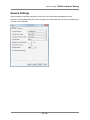
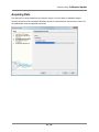
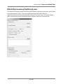
1
TEST
TEST
TEST
TEST
TEST
TEST
TEST
TEST
TEST
TEST
TEST
TEST
ISUSCom User Manual
ISUSCom 2.1.6
Document: SAT-DN-00424
2013/04/18 12:22
TEST
TEST
TEST
TEST
TEST
TEST
TEST
TEST
TEST
TEST
TEST
TEST
TEST
Prepared by: Satlantic LP
3481 North Marginal Road,
Richmond Terminal, Pier 9 Halifax, NovaScotia
B3K 5X8
Tel (902)492-4780
Fax (902)492-4781
Copyright © 2012 by Satlantic LP
Table of Contents
Overview
9
QuickStart
12
Installing
16
USB Connection
17
Dashboard
22
ISUSCom Connection Modes
28
Setup Actions
29
Settings
General Settings
Advanced Settings
Update Schedule
Calibration Update
Create calibration file
Verify calibration
File Manager
ISUS Tools
Sync Time
DAC Calibration
Create Report
Upload Firmware
Reboot
Upload Instrument Package
Command Terminal
ISUSCom Compare Calibration
ISUSCom Binary File Converter
ISUSCom Replay Data
Preferences
Application Log
Acquisition
Acquisition Views
Acquisition Monitor
Mooring Tips
Processing
ISUS Nitrate Reprocessing
ISUS-X Depth Processing
30
34
38
41
44
50
53
55
56
56
57
58
59
61
63
65
66
67
68
70
72
78
86
87
94
95
99
106
Operation Modes
107
Deployment Checklist
115
Troubleshooting
118
Common Problems
123
ISUSCom Instrument Package File
125
Index
126
ISUSCom Help - ISUSCom
ISUSCom Overview
4 / 126
Overview
ISUSCom Help - ISUSCom
Overview
Introduction
ISUSCom software is designed to make instrument setup and operation easy and robust. ISUSCom is a
windows-based application that enables the user to:
• configure ISUS for deployment
• transfer data files at full USB speed
• set sampling schedules
• perform field calibrations
• view and log data in real-time
• post process logged data
This manual describes the functions and features for the ISUSCom software. Details about the
ISUS hardware and operation can be found in the ISUS Operation Manual (Satlantic document number:
SAT-DN-0425). This manual is included on the cd shipped with each instrument
5 / 126
ISUSCom Help - ISUSCom
Overview
ISUSCom Window layout
In order to achieve a look and feel consistent with other modern windows application the ISUSCom
application was built using the Netbeans platform as its UI framework. This framework was built to give
users the maximum flexibility for advanced users but still keep the application intuitive enough so that a
new user can easily use the application out of the box.
The default view of the application is separated into a 3 main windows areas.
• The Dashboard Area
• The Main View Area
• The Output Area
The Dashboard Area
Typically the dashboard area contains the main ISUSCom dashboard component. The purpose of the
areas is to act as a starting point for the most common applications for the ISUS. All the actions of the
dashboard are available through the Menu and status bars so that it can be closed to maximize viewing
area for more advanced users.
6 / 126
ISUSCom Help - ISUSCom
Overview
The Main View Area
The main view area is located to the right of the dashboard. The main view is by default the largest area
within the application. Becuase of its larger size it is where graphs and files are initially shown.
The Output Area
The output area is located along the bottom of the application. Components placed in this area are those
usually best viewed horizontally. Typically it will contain output of log files along with smaller UI
Components that can be show in a condensed space.
Although these are the 3 default "home" locations of ISUSCom UI components, the underlying platform is
flexible enough to allow users to customize the layout of the application. Describing custom layout options
of the platform are beyond the scope of this document. More detail on doing this can be found at the
Netbeans Platform UI specification (http://ui.netbeans.org/docs/ui/ws/ws_spec.html#1).
7 / 126
ISUSCom Help - ISUSCom
Overview
Log Windows
ISUSCom comes with a some logging facilities that can be used to troubleshoot problems that might exist
within the application and with the ISUS instrument. While the application is running there are 3 logging
consoles that reside in the Output View.
• Application
The Application tab is a log of all the actions preformed by the ISUSCom windows application. It will also
record all the errors and warnings that occur while attempting to communicate and run commands on the
ISUS Device. The contents of this window are saved locally on disk in the install location under the
"<INSTALL_DIR>\eventlogs" folder.
• Setup
The Setup tab displays the console output generated by the ISUS while it executes commands. The ISUS
Setup Log is only active when the application is in Setup Mode because this is the only time when the
ISUS can receive and run commands. The contents of this log are not kept, however, all commands and
responses that are exchanged between ISUSCom and the ISUS can be found in the Application Log.
• Acquisition
The Acquisition tab displays the data that is being acquired by the ISUS while in Acquisition Mode. The
Acquisition output is only active when the application is in Acquisition mode. Although this output is not
saved, the ISUS can be be configured to log the data internally or ISUSCom can be used to log the data
in a user specified directory which then can be replayed in ISUSCom.
8 / 126
ISUSCom Help - ISUSCom
Overview
ISUSCom Files
Each ISUS instrument has unique properties which are described in configuration files. These files either
reside on the instrument or they are shipped separately for use in ISUSCom.
Below is a short description of these files and how and where they are used within the application.
• Instrument Package File (XML format) - The Instrument Package File fully describes the output data
format for that particular ISUS. This XML file is located on the ISUS instrument and is only used for
processing ISUS data on the PC side. The output format for a particular ISUS will not change, and
the Instrument Package File does not require changes either.
Note: The ISUS Instrument Package XML file can also be located on the ISUS software disk in the
"Calibration files" folder.
• Calibration File - The calibration file is located on the ISUS instrument and is loaded by the
firmware. It specifies the chemical species to be measured by their extinction coefficients and
provides the pure water spectrum for reference. Additionally, the calibration file contains information
regarding details of the calibration procedure.
The ISUS is originally shipped with a validated calibration file. Over time, the values of the reference
spectrum will marginally drift, and eventually affect the instrument accuracy. The accuracy can be
restored by measuring a new reference spectrum, and generating a new calibration file. ISUSCom
provides an easy interface to collect the new reference spectrum data, to generate the new calibration file
and to upload the new calibration file onto the instrument. Satlantic strongly advises against changing the
calibration file manually (outside ISUSCom).
• Raw Data files - Raw data files contain the output data generated during the acquisition of an ISUS.
These files may be logged internally on the ISUS or by using the Data Logging component of
ISUSCom. The format of the data frames in these files is described by the Frame definitions in the
Instrument Package File. The ISUSCom File Manager should be used to download the data files
logged internally on the ISUS to the PC and also to delete data files from the ISUS to increase the
available disk space for the next deployment.
9 / 126
ISUSCom Help - QuickStart
QuickStart
10 / 126
ISUSCom Help - QuickStart
Install and Setup
1. Run the program ISUSCom-<version>-b<build>-x86.exe (e.g. ISUSCom-2.1.0-b4-x86.exe) to
install ISUSCom and the required USB driver. See Installing ISUSCom for details on installation
requirements.
2. Wait for the FTDI Driver Installation dialog indicating that the USB driver installation is complete.
Press OK.
3. Select Start->Programs->ISUSCom->ISUSCom to run ISUSCom.
4. Connect the ISUS USB adaptor to an available USB port on your computer.
5. After a brief pause, ISUSCom will indicate that it is in Setup mode, and all buttons on the dashboard
will be enabled.
6. Select Edit->ISUS Settings to open the Settings dialog.
7. If the Settings fails to open or reports an error, then there is a problem with the USB connection.
See Troubleshooting for help.
8. Review settings. Press F1 key for help on any selected setting.
9. Press Cancel to continue with default settings or OK to apply changes.
11 / 126
ISUSCom Help - QuickStart
Test ISUS Sampling
1. Select the Run button on the ISUSCom dashboard.
2. Connect external power to the ISUS when prompted to do so.
3. Select which ISUS Sensor values you wish to view in the Start Acquisition dialog.
4. Press the Finish button to start acquiring data.
ISUSCom will display graphic plots of ISUS sensor values as they are received in real time.
To test the instrument is properly calibrated*:
1. Place the ISUS in a clean nitrate-free water sample such as deionized water (i.e. DIW) to check for
instrument drift.
2. If the nitrate reading is <-2 or >2 uM, then the instrument has drifted and the calibration should be
updated.
3. To update the calibration and correct the drift, stop the current Acquisition and run the "Calibration
Update" function.
4. Perform another Acquisition with clean deionized water to make sure the Calibration Update was
successful.
* ISUS instruments are typically run for short periods (e.g. from 10 to 30 seconds) on a schedule. When
operated in this way, no warm up of the lamp and spectrometer is required, the internal temperature will
be relatively stable and repeatable. If however the instrument is to be used continuously, such as during a
profile of the water column requiring the instrument to be on for several minutes, it is best to let the
instrument warm-up for 8-10 minutes to remove the change in instrument response that can occur due to
system heating.
12 / 126
ISUSCom Help - Installing
Installing ISUSCom
13 / 126
ISUSCom
ISUSCom Help - Installing
System Requirements
• Operating System: Windows XP, Vista, Windows 7, Windows 8
• Processor: 2.6 GHz Intel Pentium IV or equivalent
• Memory: 2 GB
• Disk space: 1 GB of free disk space
14 / 126
ISUSCom
ISUSCom Help - Installing
ISUSCom
Install process
To install the software run the self extracting executable "ISUSCom-<version>-b<build>-x86.exe" (e.g.
ISUSCom-2.1.0-b5-x86.exe). For the most part the process is self explanatory. Typically the only option
that a user may choose to change that needs an explanation is "USB FTDI D2XX driver" described
below.
Installing the FTDI USB Driver
The last step in the installer is to install the "USB FTDI D2XX driver". ISUSCom requires this to be run at
least once in order to function, on subsequent installs this step can be skipped. When the following
dialog will appears press the "Extract" button to extract the FTDI CDM Driver installation files.
Then the following "Device Driver Installation Wizard" dialog will appear. For each step of the installation
press the "Next" button and then when completed press the "Finish" button.
15 / 126
ISUSCom Help - Installing
ISUSCom
Installing the driver multiple times should not cause any problems. If for any reason a problem occurs,
please use MS Windows "Device Manager" to view the status of the USB driver and correct any
problems. For more information on installing and troubleshooting the USB driver see D2XX
driver (http://www.ftdichip.com/Drivers/D2XX.htm) page. Currently, ISUSCom uses version 2.08.28 of
the USB driver.
16 / 126
ISUSCom Help - ISUS
USB Connection
ISUS USB Connection
When the ISUS V3 USB adaptor is plugged into a USB port on the PC, the ISUS will be powered, and
ISUSCom will automatically connect to the ISUS.
The power supplied by the USB port is sufficient to operate the ISUS V3 on-board computer. As a result,
no auxiliary power is required to communicate with the instrument through the ISUSCom application.
However, for testing the ISUS operation and acquiring data, an external power supply must be connected
to the ISUS.
Detailed instructions for connecting an external power supply are outlined in the ISUS Operation Manual.
17 / 126
ISUSCom Help - ISUSCom
ISUSCom Dashboard
18 / 126
Dashboard
ISUSCom Help - ISUSCom
Dashboard
Dashboard view
The dashboard view panel contains information fields and setup actions that an ISUSCom user typically
requires. It is divided into 3 sections: info fields, setup actions and acquisition control.
19 / 126
ISUSCom Help - ISUSCom
Dashboard
Description of Fields:
The info fields are populated when the ISUS USB adapter is attached and communication with the ISUS
has been established
• Connected Mode - Describes what mode the ISUS is currently working in (ie. Disconnected,
Transition, Setup or Acquisition).
• USB Status - The current status of the USB adapter (ie. Disconnected or Connected).
• Available Lamp Time - The number of hours remaining for the lamp.
• Available Disk Space - The amount of space remaining on the ISUS storage device (Note: The
available space cannot reach 100%, due to system files such as firmware and configuration).
• ISUS Clock Time - The time reported by the ISUS clock. (Note: The time zone is based on the "Use
UTC Time" option in the ISUSCom Preferences).
• ISUS Serial Number - The Serial number of the ISUS.
• Firmware Rev - The current version of the firmware loaded on the ISUS.
20 / 126
ISUSCom Help - ISUSCom
Setup Actions
• ISUS Settings - Change ISUS Current Settings.
• Update Schedule - Create and optionally upload a new Schedule File.
• Manage Files - Manage Files on the ISUS.
• Update Calibration - Update the reference spectra in the calibration file.
21 / 126
Dashboard
ISUSCom Help - ISUSCom
Acquisition Control
• Run/Stop Acquisition - Start and stop an acquisition.
22 / 126
Dashboard
ISUSCom Help - ISUSCom
Connection Modes
ISUSCom Connection Modes
Connection mode is the current operation state the ISUS. The ISUS has two main connection modes:
Setup and Acquisition. Within each of these modes the functions available to the user are different. Below
is a summary of connection modes, transition states and available functions.
23 / 126
ISUSCom Help - ISUSCom
Connection Modes
Setup Mode
Setup mode is the main administrative mode for the ISUSCom application in which all administrative
functions are performed. When the USB cable (from the ISUS) is plugged into the USB port on the PC,
the ISUS will be powered, and ISUSCom will automatically connect to the ISUS and enter Setup Mode.
The length of time it takes for the ISUS to respond depends on the current state of the ISUS. For
example, if the ISUS was not connected to external power before connecting the USB cable, it will take
20-30 seconds for the ISUS computer to start up and initialize. If the ISUS was connected to external
power and is already on, the connection should be established within 2-3 seconds.
24 / 126
ISUSCom Help - ISUSCom
Connection Modes
Acquisition Mode
Once in Setup mode it is possible to use ISUSCom to start a data acquisition. However, the power
provided via USB is not sufficient, and main power has to be connected. Acquisition mode is entered by
selecting the "Run" icon on the main dashboard. This function causes the connected ISUS to leave Setup
mode, turn on its hardware and begin sending data. In Acquisition Mode, incoming data can be viewed
graphically and logged.
25 / 126
ISUSCom Help - ISUSCom
Connection Modes
Disconnected Mode
Strictly speaking, Disconnected Mode is not a mode like Setup Mode or Acquisition Mode. Disconnected
mode indicates that USB is not connected and the ISUS is offline. Only those functions that can be
performed offline are available in ISUSCom in Disconnected Mode. Instead of loading information from
the ISUS, these operations load data from files on disk and typically result in new output files being
created locally that can be uploaded later if required (e.g. updated calibration file).
26 / 126
ISUSCom Help - ISUSCom
Connection Modes
Transition Mode
Transition mode is used to indicate to the user that the ISUS is currently not responsive because it is
switching its internal operating mode. Typically the ISUS should not remain in this mode for more than a
minute. When in transition mode, commands sent to the ISUS will be ignored and a warning message will
appear.
27 / 126
ISUSCom Help - ISUSCom
Connection Modes
Important Note: Disconnecting USB
When the USB cable is removed and external power is connected, the ISUS will remain in the mode that
it was last in. It is Important to note this because if the ISUS is in Acquisition mode this could result in the
unnecessary burning of limited lamp hours. If the ISUS is in Setup mode and the ISUS is deployed this
could result in the the ISUS not collecting any data.
28 / 126
ISUSCom Help - ISUS
Setup Mode Actions
ISUS Setup Mode Actions
When the ISUS is in setup mode all of the management type functions are enabled. Below are a list of
these functions.
Edit Settings
Update Schedule
Update Calibration
File Manager
Sync ISUS Time
DAC Calibration
Summary Report
Upload Firmware
Reboot
Upload Instrument Package
Compare Calibration
Binary File Conversion
Replay ISUS Data
Preferences
29 / 126
ISUSCom Help - Edit
Settings
Edit Settings
The operation of the ISUS instrument is controlled by a number of settings parameters. Different
parameter selections provide ways to prepare the ISUS for different deployment scenarios.
In setup mode, settings parameters can be changed via the settings panel. The settings panel shows the
current configuration of the ISUS and any settings changed on this Dialog will be applied immediately
when the Upload buttons is hit.
The settings are divided up into two areas, general settings and advanced.
General Settings
Advanced Settings
30 / 126
ISUSCom Help - ISUSCom
ISUSCom General Setting
31 / 126
General Setting
ISUSCom Help - ISUSCom
General Setting
General Settings
General settings are typically changed by ISUS users in the initial setup and deployment of the
instrument. These settings effect the mode of operation of the instrument and not the overall stability and
accuracy of the ISUS data.
32 / 126
ISUSCom Help - ISUSCom
General Setting
Description of Fields:
Operational Mode
The ISUS has been designed with several user-selectable operating modes: CONTINUOUS,
FIXEDTIME, SCHEDULED, BENCHTOP and TRIGGERED. Future ISUS units may include additional
operating modes not described here. The operating mode is retained in the ISUS’s non-volatile memory.
At power-up, the operating mode is checked and the necessary initialization actions are performed. If the
user changes the operating mode, power will have to be removed and then reapplied (after approximately
1 minute, in order to discharge the instrument internal power protection charge). See Operation Modes for
more detail.
Transfer Frame Mode
The results of each measurement are collected in individual frames. (See “Frame Output Modes” for
details.) This option determines what frame type will be transmitted over the USB or Serial connection.
Options are NONE, a full frame in ASCII format, a full frame in binary format, or a short (concentration)
frame. The instrument default is to send full ASCII frames. For the purpose of post-processing, full frames
are essential. Disadvantages of full frames are increased transfer times. It is not possible to disable both
data transfer and data logging (see next option).
Logging to File Frame Mode
The results of each measurement are collected in individual frames. (See “Frame Output Modes” for
details.) This option determines what frame type will be logged to internal data file. Options are NONE, a
full frame in ASCII format, a full frame in binary format, or a short (concentration) frame. The instrument
default is to log full ASCII frames. For the purpose of post-processing, full frames are essential.
Disadvantages of logging full frames are increased write time and disk use. If no post-processing is
required logging of data can be disabled. In this case, the data rate may increase slightly, due to reduced
processing requirements. There is no possibility to recover data without logging to file. It is not possible to
disable both data logging and data transfer (see previous option).
Log File Mode
When in SCHEDULED mode (or CONTINUOUS or FIXEDTIME mode for Firmware Rev 3.1.3 or higher),
internally logged data is stored either in one file per day, or in one file per scheduled event.
Logging Time in Fixed Mode
When in FIXEDTIME mode, the instrument operates for a fixed time, and then enters the menu interface.
In TRIGGERED mode, this is the maximum acquisition duration.
Deployment Counter
The deployment counter determines the next file name to be used for internal logging of data:
DIVEnnn.DAT, where nnn is the deployment counter. If a file by that name already exists, the data will be
33 / 126
ISUSCom Help - ISUSCom
General Setting
appended. The counter is incremented from deployment to deployment, and will be reset to 1 upon
reaching a maximum value of 999. It is possible to set the counter to any value in the 1 - 999 range.
Serial Baud Rate
The data rate for the serial telemetry channel may be one of 9600, 19200 or 38400 bps. To operate at a
new baud rate, it is necessary to remove power from the instrument, and restart it.
Enable Status Messages
Normally the instrument generates messages during its operation, to inform the user of what is going on.
It may be desirable to reduce the amount of output generated. Error messages are not suppressed when
status messages are disabled.
34 / 126
ISUSCom Help - ISUSCom
ISUSCom Advanced Settings
35 / 126
Advanced Settings
ISUSCom Help - ISUSCom
Advanced Settings
Advanced Settings
Advanced options are usually not changes. Under special circumstances or for specific reasons, changing
these options may be necessary. It is recommended that such changes only be done when the effects
are fully understood. Typically, these advanced settings are modified following communication with
a Satlantic representative.
36 / 126
ISUSCom Help - ISUSCom
Advanced Settings
Description of Fields:
CAUTION: These setting should only be changed after consultation with a Satlantic
representative.
Dark Correction Mode
The instrument has a lamp shutter to generate dark sample readings. In case of a shutter failure in a
saltwater environment only, it is possible to estimate dark values by using spectral values in the very short
wavelength range instead. Saltwater has the property to completely absorb UV in the very short
wavelength range. This option is provided in order to permit data acquisition during a partial instrument
failure.
Baseline Order
The baseline order of the instrument is nominally set to 1 (linear), and should not be changed. Under
special conditions, a baseline order of 2 (quadratic) has been shown to produce better results.
Fitting Range
The fitting range defines the wavelength range over which measurements are used for estimating the
concentration(s). The instrument supports a contiguous wavelength range, which defaults to 217.5 nm to
240 nm. The best fitting range depends on the type of water the instrument is used in. The nominal fitting
range is appropriate for both freshwater and seawater with moderate amounts of secondary absorbers,
e.g. dissolved organic matter or particulate matter. In very clear water, the fitting range can be extended,
which may reduce the noise level in the measured chemical species due to the availability of more data
points for the fitting routine. If, on the other hand, chemical species with absorption in the longer
wavelength range are present, these introduce a bias into the calculated concentrations. Changing the
nominal fitting range is therefore only advisable if the expected water composition is known in advance.
Nitrate & Auxiliary DAC Ranges
The ISUS instrument generates analog output for the measured nitrate and auxiliary fitting data (see
Instrument manual for more detailed information). The minimum and maximum values of the data range
correspond to the minimum and maximum output voltages. The selected range should correspond to the
expected measurement range. Selecting a too narrow range may cause loss of information; a too wide
range may cause reduced resolution.
Initial Power-up Delay
The lamp ignites best after reaching a minimum temperature. The warm-up period is initially set to 5
seconds. When the lamp ages and the instrument generates log messages about problems to turn on the
lamp, a warm-up period of 10 to 15 seconds may become necessary. Normally, this setting should not be
changed.
Integration Period
37 / 126
ISUSCom Help - ISUSCom
Advanced Settings
Selecting this command allows the user to set the spectrometer integration time, in milliseconds. The
normal setting is between 700 and 850 ms. Changing this value invalidates the instrument calibration.
Light Frames (per Dark Frame)
A complete acquisition cycle consists in taking a fixed number of dark samples followed by another fixed
number of light samples. Normally, 1 dark sample and 10 light samples are taken. Dark values should be
taken regularly, because they compensate the thermal electronic noise of the instrument. If more than
one dark reading is taken, an average value is calculated.
38 / 126
ISUSCom Help - ISUSCom
ISUSCom Update Schedule
39 / 126
Update Schedule
ISUSCom Help - ISUSCom
Update Schedule
Update Schedule
The ISUS instrument can work in scheduled mode to periodically power up and collect data. The main
reason to use a schedule is to conserve energy and extend the lifetime of the ISUS.
The details of the schedule are specified within a file that resides on the ISUS. The format of that
schedule file is sensitive to formatting and should only be edited manually by someone who fully
understands the format. "Appendix I" in the Operation Manual for MBARI-ISUS explains the file format.
The Update Schedule Action generates and uploads general purpose schedule files. The Update
Schedule Action allows you to specify all the options required to create a schedule. It will then create a
valid schedule file that can be saved and/or uploaded to the ISUS.
It is important to note:
The Update Schedule Action does not show the properties of the existing schedule when it is
opened; it shows the setting of the last successfully saved schedule file. When using the New
Schedule Action to upload a new schedule file, the existing schedule on the ISUS will be
overwritten.
40 / 126
ISUSCom Help - ISUSCom
Update Schedule
Description of Fields:
Frequency
The frequency controls how often the instrument will wake up and collect data
Offset (min)
The number of minutes the schedule will be offset from the full hour(s). E.g., for a schedule of two times
per hour, an offset of five minutes will start the instrument at five minutes past each hour and five minutes
past each half hour.
Logging Delay (sec)
Specifies how many seconds to allow for the instrument to stabilize before collecting data. This is in
addition to a mandatory 25 seconds for ISUS boot up.
Duration (sec)
Specifies how many seconds each data acquisition will last.
Acquisition Blackout Period
Allows the user to specify a blackout window where no data will be collected. These times use the
24 hour clock. Within this time period the schedule will not apply. Used for e.g. acquisitions only
during daylight hours.
41 / 126
ISUSCom Help - Calibration
Calibration Update Process
42 / 126
Update Process
ISUSCom Help - Calibration
Update Process
Reality Check
ISUS users should check instrument performance periodically and before critical deployments to ensure
instrument accuracy is optimized. Satlantic recommends users measure the nitrate concentration in
ultra-clean de-ionized water (DIW) to ensure the ISUS measures 0 +/-2 µM Nitrate. Ensure that the probe
tip is clean and not damaged in any way. Use KIMWIPES and isopropyl alcohol to clean the probe tip.
Place the ISUS instrument on a bench, start it (see ISUS manual for details) and let it warm-up for at least
10 minutes. The warm-up period is required to achieve relative stability of the ISUS internal temperature.
Using a clean cup (or vial or test-tube), submerse the probe tip in ultra-clean de-ionized water (DIW).
Acquire 30 seconds of data noting the calculated nitrate value. If it is not 0 +/- 2 µM, run the update
calibration procedure. It is very important to make sure there are no air bubbles on the probe lenses
when measuring the DIW samples. The most common source of error when testing an ISUS instrument in
bench top mode is the formation of bubbles on the probe tip. If you suspect a bubble, note the number of
counts at 220 nm on the light spectrum graph. Replace the DIW sample and check whether the counts
have stayed roughly the same. A bubble will cause the optical counts to drop.
Checking Accuracy Using a Water Sample of Known Concentration
The accuracy check requires a water sample with known nitrate and salinity values. Again, it is important
that the probe tip is clean and there are no air bubbles on the probe lenses. Submerse the window into
the prepared water standard. Using ISUSCom, monitor the nitrate concentration values. The ISUS nitrate
concentrations should not deviate from the expected value by more than +/- 2 µM.
43 / 126
ISUSCom Help - Calibration
Update Process
Updating Calibration of ISUS using ISUSCom
If the instrument does not read 0 +/-2 µM Nitrate for the DIW sample, we strongly recommend removing
the sample, cleaning the tip and replacing the sample ensuring no bubbles cling to the lens surfaces. If
the instrument still does not measure the expected value, some instrument drift may have occurred over
time, and an update of the calibration file may be required. ISUSCom provides a GUI to automate the
steps necessary to update the calibration reference spectrum. This process effectively re-zeros the
instrument. To create an ISUS calibration file, two basic steps are required:
• Create updated calibration file
• Verify new calibration file
44 / 126
ISUSCom Help - Calibration
Update
Calibration Update
Note: Calibration Update function can only be used if the instrument is set to "Full Binary" or "Full
ASCII" modes, smaller frame formats do not contain enough information for this process.
45 / 126
ISUSCom Help - Calibration
Update
Place the ISUS in Reference Sample
Start the Update Calibration function in ISUSCom and follow the prompts to submerse the probe in a
sample of ultra-clean DIW.
46 / 126
ISUSCom Help - Calibration
Update
Retrieve Base Calibration File from ISUS
The second step in this process is to retrieve the base calibration file from the ISUS. The base calibration
file is the calibration file that is currently being used on the ISUS. (The one that has drifted and has to be
re-calibrated.) ISUSCom retrieves this calibration file automatically.
47 / 126
ISUSCom Help - Calibration
Update
Acquiring Data
The next step is to acquire data from the reference sample. From this data, an updated averaged
reference spectrum will be calculated. ISUSCom will start to collect data from the instrument, "Next" will
be enabled when it has enough data to proceed.
48 / 126
ISUSCom Help - Calibration
Update
Show Reference Spectra Comparison
Before uploading and/or saving the new calibration file, ISUSCom offers the option to view a graph
comparing the base reference spectrum to the new reference spectrum. The changes should be gradual
over the instruments wavelength range, and are typically within 10% above 200 nm. The critical
wavelength range is from 217 nm to 240 nm.
49 / 126
ISUSCom Help - Calibration
Update
Deploying new Calibration File
The final optional step is to upload the new calibration file to the ISUS instrument flash disk. The file can
also be saved locally for data post-processing or upload at a later time. ISUSCom has the ability to store
26 different revisions of calibration file on the instrument. When uploading, the user has the choice to
either re-use the current revision or create a new one on the ISUS.
When a new calibration file is created and uploaded, it is recommended that users do a reality check with
a water sample of known salinity and nitrate concentration. This water sample can be prepared in a
laboratory or one could use in situ measurements. It is recommended to use a water sample with the
highest expected nitrate concentration (e.g. for measurements in ocean one could use a sample with
nitrate concentrations around 30 µM).
50 / 126
ISUSCom Help - Verification
Verification of Calibration File
51 / 126
of Calibration File
ISUSCom Help - Verification
of Calibration File
Checking Reference Spectrum against a DIW Sample
The procedure for verifying the new calibration file essentially repeats the steps taken to acquire the
reference spectrum. Ensure that the probe tip is clean and not damaged in any way. Use KIMWIPES and
isopropyl alcohol to clean the probe tip. Start the ISUS and let it warm-up for about 15 minutes, if it has
not been warmed up already. Then submerse the probe tip in a sample of ultra-clean DIW and monitor
the nitrate concentration values using ISUSCom. If the nitrate values deviate from 0 by more than +/- 2
µM, create a new calibration file as described in the section "Create Updated Calibration File". Upload the
new calibration file onto the ISUS and repeat the current step.
52 / 126
ISUSCom Help - Verification
of Calibration File
Checking Accuracy Using a Seawater Sample of Known
Concentration
The accuracy check requires a seawater solution with known nitrate and salinity values. Again, it is
important to have a clean and dry probe tip. After approximately 10 minutes of warm-up of the ISUS,
submerse the probe tip into the prepared seawater standard. Using ISUSCom, monitor the nitrate
concentration values. The ISUS nitrate concentrations should not deviate from the expected value by
more than +/- 2 µM.
53 / 126
ISUSCom Help - ISUSCom
ISUSCom File Manager
54 / 126
File Manager
ISUSCom Help - ISUSCom
File Manager
File Manager
The ISUS Instrument stores the data it collects in files on its local drive. In addition to these data files the
ISUS can store up to 26 different revisions of its calibration file, internal log files, its current schedule and
the firmware files it needs to operate.
The ISUSCom File Manager gives an easy way to manage the parts of the ISUS file system that need to
be actively managed. Within the manager there are 4 tabs, each tab representing one file type. Within
each tab only the actions that are valid for that type will be enabled.
55 / 126
ISUSCom Help - ISUSCom
Sync ISUS Time
ISUSCom Sync ISUS Time
This command synchronizes the time on the ISUS to the time on the computer. When selecting "Sync
ISUS Time" from the Tools Menu, a dialog will appear showing both the ISUS clock time and the
computer's clock time. The time zone used for both time values is based on the "Use UTC Time" option in
the ISUSCom Preferences. To synchronize the ISUS clock to the time on the computer, press the "Sync
Time" button and the computer's current time is sent to the ISUS. The ISUSCom dashboard is
then updated to display the new ISUS clock time.
56 / 126
ISUSCom Help - DAC
Calibration
DAC Calibration
The DAC Calibration function is used to in the procedure for interfacing the ISUS to a Sea-Bird CTD
profiler. By selecting the Low, High and Stop buttons commands are sent to the ISUS that send voltages
to configure an attached CTD. These commands are only available when external power is connected.
Detailed instructions for this procedure are outlined in an Appendix of the ISUS Operation Manual.
57 / 126
ISUSCom Help - Summary
Report
Summary Report
Before a deployment or when it is important to record the complete state of the ISUS instrument, it is
recommended to create a Summary Report. To do this, enter setup mode and select Summary Report
under the Tools Menu. This action will show the Summary Report Dialog.
Enter a valid save location on disk and a comment that describes information about why the current
summary report is being created.
58 / 126
ISUSCom Help - ISUSCom
ISUSCom Upload Firmware
59 / 126
Upload Firmware
ISUSCom Help - ISUSCom
Upload Firmware
Uploading new firmware
Satlantic may occasionally release updates to the ISUS firmware. ISUSCom provides a GUI to validate
and install a new firmware version.
Caution: The ISUSCom software performs as many checks as possible before attempting an upgrade,
but there is always some risk involved in upgrading. Because of this Satlantic advises users to be
cautions when performing an upgrade. A firmware upgrade amounts to replacing the existing firmware by
a new firmware. If the replacement procedure is interrupted, the instrument is left without a working
firmware: The old firmware has been removed, but the new one is not installed. In this scenario, the ISUS
is without a firmware, and can no longer operate. The instrument may have to be sent back to Satlantic to
reload a new firmware manually. Because of this risk, we ask users to only upgrade to a new firmware
version when a bug fix or new feature is required.
Procedure
In order to perform the upgrade you require
• The new firmware file from Satlantic.
• The verification code generated by Satlantic that corresponds to that firmware file
From the Tools Menu, select the Upload Firmware action to bring up the Upload Firmware action dialog.
Provide both the location of the new firmware file and its verification code, then hit the upload button.
When the new firmware is uploaded the ISUS uses the verification code to determine if the new firmware
is valid. The entire upload procedure should take about one minute to perform. When the firmware upload
is successful, a dialog is displayed to allow an immediate reboot of the ISUS. In case the uploaded
firmware file is invalid (e.g. mismatch of the verification code) the upgrade procedure is terminated.
60 / 126
ISUSCom Help - ISUSCom
Reboot
ISUSCom Reboot
The reboot command will terminate the current execution of the ISUS firmware. A new execution will
commence, using the latest settings parameters. A reboot is necessary when changing the operation
mode of the instrument.
When the reboot action is selected, the user will be prompted with a confirmation dialog. Once confirmed,
the ISUS will be sent the reboot command. ISUSCom can not communicate with the ISUS until the reboot
has completed. Once the reboot time has expired ISUSCom resumes communication with the ISUS and
commands the ISUS to enter its setup mode.
61 / 126
ISUSCom Help - ISUSCom
Upload Instrument File
ISUSCom Upload Instrument File
62 / 126
ISUSCom Help - ISUSCom
Upload Instrument File
Instrument Package File
Each ISUS that is shipped provides an XML file that contains the frame format for the ISUS. As with all
new Satlantic instrumentation this file follows the Satlantic XML Instrument File Format. This standard
defines how Satlantic frames are composed and interpreted. A full explanation of this standard is beyond
the scope of this document but is full explained with the
SAT-DN-00157_Instrument_File_Format document.
The elements of this XML file are based upon the particular frames contents of the ISUS. These contents
are fully described within the "Operation Manual for the ISUS Instrument. Most users will probably never
have to edit this XML instrument file. In cases where it is necessary we ask that this should be done in
conjunction with a Satlantic representative.
63 / 126
ISUSCom Help - ISUSCom
Upload Instrument File
Upload Instrument XML File
Each ISUS is shipped with an XML file that describes the frame and sensor definitions that are associated
with a particular instrument. Without this file, ISUSCom will fail to display ISUS data. This function is
mainly used by Satlantic personnel to upload this file to the instrument before it leaves Satlantic.
64 / 126
ISUSCom Help - Command
Terminal
Command Terminal
To issue commands directly to the ISUS:
1. Ensure that the ISUS is connected and in Setup mode.
2. Open Command Window
3. Select desired command from the drop-down list, or
4. Press TAB key to iterate through commands, or
5. Type a command directly (with assistive command completion)
6. Press Submit button to send the command to the ISUS.
CAUTION: Do not issue any command without fully understanding its effect. Uninformed use of the
command window can render the ISUS inoperable.
65 / 126
ISUSCom Help - ISUSCom
Compare Calibration
ISUSCom Compare Calibration
This tool allows comparison for two ISUS calibration files. Calibration files contains wavelength
information, extinction coefficients for nitrate and bromide and a reference spectrum. This function
compares the reference spectra from two different calibration files. This function is useful for gauging
instrument drift that may have occurred between calibration updates. It is automatically preformed as part
of the Update Calibration procedure.
66 / 126
ISUSCom Help - Convert
Data Files
Convert Data Files
This tool allows conversion of FULL_BINARY files to ASCII.
Procedure for displaying ear data
1. Select View->Convert Data File from the ISUSCom menu bar.
2. Select the Instrument Package File*, Output Directory, Raw Data File(s) in the Convert
Raw Files to CSV dialog.
3. Press the Ok button to start converting logged data.
* To perform this ISUSCom operation the ISUS Instrument Package XML File is required. This ISUS
configuration file is provided on the ISUS software disk in the "Calibration files" folder.
67 / 126
ISUSCom Help - Convert
Data Files
View Logged Data
The view raw data function allows users to view the contents of raw data files in the ISUSCom user
interface, this is especially important for FULL_BINARY data that cannot be easily viewed.
68 / 126
ISUSCom Help - Convert
Data Files
Procedure for displaying ear data
1. Select View->Replay Logged Data from the ISUSCom menu bar.
2. Select the Instrument Package File*, ISUS Calibration File, Raw Data File in the Replay Logged
Data dialog.
3. Select the Raw File Frame Mode of the logged data file and which Sensor values you wish to view
in the Replay Logged Data dialog.
4. Press the Finish button to start replaying logged data.
ISUSCom will display graphic plots of ISUS sensor readings recorded in the selected raw data file.
5. Press the Stop button on the ISUSCom dashboard to stop replaying the raw data file.
* To perform this ISUSCom operation the ISUS Instrument Package XML File is required. This ISUS
configuration file is provided on the ISUS software disk in the "Calibration files" folder.
69 / 126
ISUSCom Help - ISUSCom
ISUSCom Preferences
ISUSCom preferences are used to hold ISUSCom specific settings that are locally stored.
70 / 126
Preferences
ISUSCom Help - ISUSCom
Preferences
Description of Fields:
Nitrate Units
Internally the ISUS always uses uMolar for Nitrate units. ISUSCom can be configured to convert and
display these values to mg/L within its interface.
ISUSCom Response Timeout
The amount of time that ISUSCom will wait for a response from a ISUS. Used for all ISUS commands
except file listing requests..
ISUSCom File Listing Timeout
The amount of time that ISUSCom will wait for a response from a file list ISUS command. These
commands typically take longer to run on the ISUS so this setting was added specifically for these
commands.
ISUSCom Dashboard Retries
Number of times ISUSCom will send a command to populate the dashboard before giving up.
Sensor Value Decimal Places
The number of decimal places to show for all sensor values displayed on the UI.
Use UTC Time
Used to toggle between UTC or the computer's Time Zone for all time values displayed on the UI.
Remember Windows Locations
Remember windows locations from one ISUSCom session to another.
Default Data Directory
Directory where data will be logged to by default.
Prompt at startup
Prompt the user each time to configure the default data directory, especially useful if there are multiple
ISUS's being used on one computer.
71 / 126
ISUSCom Help - ISUSCom
Application Log
ISUSCom Application Log
This tool allows for configuration of the log files ISUSCom outputs. It can be set for very brief or verbose
logging depending on what the needs of the user are. The log file generated by ISUSCom are invaluable
for diagnosing problems and will most likely be requested by Satlantic support.
72 / 126
ISUSCom Help - ISUSCom
Description of Fields:
73 / 126
Application Log
ISUSCom Help - ISUSCom
Application Log
Message Log Level
The dropdown box allows users to select the sensitivity of the ISUSCom Application logs. The following
log levels can be selected. All log levels are cumulative, (i.e. INFO level also logs WARN and ERROR)
• TRACE - Most detailed level of logging, generates very large log files, should only be used by
support for troubleshooting.
• DEBUG - High level log logging detailed, mainly used by support for troubleshooting probelms.
• INFO - Typical log level for application, contains logs for all high level operations.
• WARN - Only logs warnings that occur in application, remove all expected "info" log messages.
• ERROR - Only logs errors, typically errors require investigation and user intervention.
74 / 126
ISUSCom Help - ISUSCom
Application Log
Display Dialog for Error level Messages
Enabling this setting allows displays a pop up message for all ERROR and SEVERE messages to ensure
they are not missed since these are typically more severe errors that should not be ignored.
75 / 126
ISUSCom Help - ISUSCom
Application Log
Message Log File
Allows users to control mechanism in which log files are stored on disk, if daily is selected a new log file is
created each day. If Rolling is selected new logs will delete old log files once file size and number of files
threshold has been reached.
76 / 126
ISUSCom Help - ISUSCom
Location
The location in which log files are stored on disk, useful when looking for files.
77 / 126
Application Log
ISUSCom Help - ISUSCom
ISUSCom Acquisition
78 / 126
Acquisition
ISUSCom Help - ISUSCom
Acquisition
Starting an Acquisition
The main purpose of the ISUS is to acquire data.
• When an ISUS is powered up solely using main power it will automatically go into acquisition mode.
The way in which it will acquire data (Continuous, Scheduled, ...) will depend upon how the
instrument was configured.
• When an ISUS is powered up by USB (with ISUSCom running) it assumes it is being configured and
will automatically be sent into Setup mode and await commands from the USB interface. From
Setup mode an acquisition with real time display can be started by pressing the "Run" button. The
description of this Real time display acquisition is provided below.
When both main and USB power are removed from the ISUS, it will execute a controlled shutdown. The
power for this shutdown resides in electric capacitors that are charged whenever the instrument is
powered up. It is advisable to let the controlled shutdown run its course and the capacitors discharge
before reconnecting power. A wait time of 30 seconds is sufficient; if reconnecting too early, the
instrument might be brought into an intermediate, undefined state, where it does not respond.
79 / 126
ISUSCom Help - ISUSCom
Acquisition
Starting an Acquisition in ISUSCom with Real Time Display
When starting an acquisition within ISUSCom, the Real Time Display allows monitoring of the generated
data. Before deployment it is advisable to confirm that the generated data are within the expected range.
This check is particularly important after an updated calibration file has been uploaded onto the ISUS.
When starting an acquisition through ISUSCom, the following dialog will appear.
80 / 126
ISUSCom Help - ISUSCom
Acquisition
Description of fields
Operational Mode
Displays the current user-configurable operational mode of the ISUS.
Frame Transfer Mode
Three frame output formats are available in the ISUS: Concentration ASCII, Full ASCII (default) and Full
BINARY. All three formats are described within the instrument XML file. Both ASCII and BINARY Full
modes provide all available information to the user, at the expense of increased frame and log file size.
The Concentration mode provides a greatly reduced frame, containing only a time-stamp, the nitrate
concentration and auxiliary fitting results as calculated by the ISUS. The frame format for each mode is
given in the table below. Please note that either frame output mode may be used regardless of the
operation mode of the instrument.
In ASCII frames, data fields are comma-delimited and of variable size.
In BINARY frames, separate fields are of a fixed length, and thus do not require delimiters. The absence
of delimiters and the inherent compact representation of data leads to a reduction of the frame size by a
factor of nearly three.
BINARY frames have to be converted to ASCII (e.g using SatCon) data for use in most desktop
applications.
Sensors
Each ISUS is pre-configured with a valid calibration file. The calibration file of the ISUS lists the chemical
species that the ISUS is configured to collect. The ISUS can be configured to collect up to 4 chemical
species. When starting an acquisition, ISUSCom allows you to select which of these chemical species
and/or ancillary sensors you wish to view within the graph and real time data viewer.
Aqusition Dispaly Windows
ISUSCom Mooring tips
81 / 126
ISUSCom Help - ISUSCom
ISUSCom Acquisition Display
82 / 126
Acquisition Display
ISUSCom Help - ISUSCom
Acquisition Display
Graph Windows
ISUSCom is setup to allow you to view the most commonly required graphical representation of data
collected from the ISUS. The graphs can either be generated from a live acquisition or they can be
recreated from a raw data file collected in the past. The two types of graphs are described below.
Time Series Graphs
The time series graphs show each (selected) chemical species and/or ancillary sensor as it changes over
time. The ISUS instrument currently collects data on 2 chemical species, nitrate and bromide. The main
function of ISUS is to collect Nitrate data and the time series view enables the user to track and visualize
changes in nitrate concentration over time. This may be useful when checking standards or monitoring a
solution in flow through mode. The time axis label shows the time zone of the time values based on the
"Use UTC Time" option in the ISUSCom Preferences.
Spectra Graphs
The spectra graphs show raw counts for both the light and dark frames for each wavelength from about
190nm to 400nm. This view displays the amount of light at each wavelength reaching the spectrometer.
"Counts" are a representation of the spectrometer voltage output that is directly proportional to the
amount of light reaching the diodes. The three main components that make up the optical path in the
ISUS are the UV lamp, the fiber optic probe (includes the sample tip) and the spectrometer. The spectra
displayed in the spectral view are a combination of the spectral shape of the lamp output, the
transmission characteristics of the fiber optic probe, and the relative response of the spectrometer diodes.
The "in-air" spectra will always have the same characteristic shape. When a sample is added, the
absorption characteristics of the dissolved chemical species such as nitrate will change the spectral
83 / 126
ISUSCom Help - ISUSCom
Acquisition Display
shape displayed. For example, when sampling salt water, the first few wavelengths will be absorbed
completely by the bromide ion.
Total Absorbance Graphs
The total absorbance graph displays calculated absorbance from 210 nm to 370 nm. The total
absorbance display was added to ISUSCom as an alternative to the Spectra Graph to help users interpret
and understand sample spectra. Interpreting the absorbance graph requires no prior knowledge of the
typical shape of the measured spectra. When measuring a pure de-ionized water sample, the absorbance
graph should be flat. As absorbing species such as nitrate and bromide are added to samples, the
absorbance will increase exponentially with decreasing wavelength.
84 / 126
ISUSCom Help - ISUSCom
Acquisition Display
Sensor Data Viewer
When an acquisition starts the real time view will be displayed in the bottom left part of the application.
This component displays the last known values reported for each chemical species and/or ancillary
sensor. These values are the identical values graphed in the sensor time series graphs. The time stamp
value is obtained from the date and time sensors in each data frame. The time zone used for the time
stamp value is based on the "Use UTC Time" option in the ISUSCom Preferences.
Log Management Window
85 / 126
ISUSCom Help - ISUSCom
Acquisition Display
The log management window will allow you to create a separate log that is a subset of the current
acquisition. When an active acquisition is underway press the Start Log button to begin logging data to a
local file. Once enough data has been logged simply press the Stop Log button to finish logging. When
the Auto Log option is enabled the Log Duration and Log Interval time values (hh:mm:ss) are used to log
data to multiple data files when the Start Log button is pressed.
86 / 126
ISUSCom Help - SUNACom
SUNACom Acquisition Monitor
87 / 126
Acquisition Monitor
ISUSCom Help - SUNACom
Acquisition Monitor
Data Acquisition Monitor
Acquisition Monitor can be found from the Window menu on the toolbar or the Nitrate viewer "Acquisition
Errors" details button.
The Acquisition Monitor window allows users to see the overall results of an acquisition. It is useful in
displaying problems that are occurring within the frame that the ISUS instrument is outputting.
88 / 126
ISUSCom Help - SUNACom
Acquisition Monitor
Description of Fields:
The statistics are populated when an acquisition is active, In most cases the number of erroneous frames
are minimal, or none. This panel can be useful in determining when and why errors are occurring.
89 / 126
ISUSCom Help - SUNACom
Acquisition Monitor
Frame Statistics
• Frame Id - The unique identifier of the frame in the Satlantic instrument package definition.
• Read - The number of valid frames read during an acquisition for a particular frame.
• Errors - The number of frames read that contained errors during an acquisition for a particular
frame.
• Checksum Errors - The number of frames that contained checksum errors, typically discarded.
• Counter Errors - The number of frames that contained counter errors, typically not discarded.
• Status Errors - The number of frames that contained status errors, typically discarded.
• Fitting Errors - The number of frames that contained fitting errors, typically discarded.
90 / 126
ISUSCom Help - Tips
Tips for Mooring ISUS
91 / 126
for Mooring ISUS
ISUSCom Help - Tips
for Mooring ISUS
To prepare the ISUS for mooring deployment:
• Check the Available Disk Space on the ISUS. If there is not enough for the deployment then use
the ISUSCom File Manager to download and/or delete all data files from the ISUS.
• Create and Upload the desired Schedule.txt file using ISUSCom
• Set the ISUS operating mode to SCHEDULED
• For long term deployments where more than 100MB of data will be logged, set the file logging
option to “DAILY” rather than the default “SINGLE”. We have noticed that if the SPECTRA.DAT file
gets to be very big, the frame rate slows down slightly as the firmware takes longer to append to
the larger file (this applies only to firmware versions before 2.8)
• Reboot ISUS and ensure that schedule is valid and working
• Clean the probe tip with isopropanol and Q-tips
• Mount ISUS on mooring in horizontal position with gap in probe tip open vertically (see below)
• Install bio-fouling guard with the guard and probe tip both flooded if possible (this reduces the
possibility of trapping air in the probe tip)
92 / 126
ISUSCom Help - Tips
for Mooring ISUS
Mooring Data
The main issues effecting mooring data quality are bio-fouling and sediment buildup. To mitigate the
effects of these two factors, we recommend users install the anti bio-fouling guard and:
• Mount the ISUS in the horizontal position with the gap in the probe tip open vertically (i.e. opening
up for air to escape and opening down for sediment to sink) to reduce the possibility of sediment
collection on the probe mirror. Anything that interferes with the light path may adversely affect the
data.
• Experiment with different mesh sizes in the anti bio-fouling guard. The standard mesh size is
100µm, but 50µm and other sizes are also available. Depending on the type of environment, users
have to balance the trade offs between keeping bugs and debris out and clogging the filter and
reducing water flow. In high sediment areas, some users have found using no mesh works better,
since the smallest particles pass through the mesh and accumulate inside. In this case the mesh
can act like a trap and keep sediment in.
• In areas with robust biological activity, fouling may occur in spite of the copper ions released by the
guard. In this case, we recommend a more intense sampling schedule to increase the UV radiation
passing through the probe tip. Because the ISUS outputs short wavelength UV, the more you
sample, the cleaner the tip will stay. The tradeoff here is that power is always an issue and the
sampling schedule is always constrained by power. Keeping this in mind, users should opt for the
most aggressive sampling schedule that the power budget and memory will allow.
• In static areas with low water flow, various low power pumps can be used to flush the probe tip
area with sample water prior to obtaining data. Flushing the probe helps reduce bio-fouling and
extend the length of useful deployments. In-line filters may also be used in conjunction with pumps,
but clogging can become an issue in highly turbid waters. Users must weigh the benefits of filtering
vs. the consequences of clogging.
Tips for Profiling with ISUS
• Set the ISUS operating mode to CONTINUOUS
• Clean the probe tip with alcohol and Q-tips prior to each deployment
• Let the ISUS warm up for 8-10 minutes prior to each cast. Normal operation of a CTD profile
usually calls for surface soak of a couple of minutes to let the pumps start up and instruments
equilibrate. We find we get the best results when we apply power to the ISUS 8-10 minutes prior to
putting the package in the water. This provides enough time to let the lamp output stabilize.
• Once a day check instrument stability by measuring nitrate in a pure water sample (e.g. Millipore
DIW) as described in the “Long-Term Drift” section below.
Compensating for Instrument Offset
93 / 126
ISUSCom Help - Tips
for Mooring ISUS
Two types of instrument offsets are possible with ISUS nitrate sensors. One is associated with a
long-term drift in the instrument response caused by changes in the transmission properties in the
internal optical components and the other is associated with interfering species present in the water.
Long-Term Drift
To check your instrument for long-term drift, turn on the ISUS, let it warm up for 8-10 minutes and
measure a sample of ultra-clean de-ionized water (DIW). If the nitrate reading is >-2 or <+2, the
instrument response has not drifted. If it has drifted, you can remove the drift by updating the reference
spectrum in the cal file. This is done using the program ISUSCom.
Interfering Species
Various dissolved and particulate substances in the water can interfere with the UV spectra sampled for
nitrate analysis. Particulate matter, if suspended in the water column (i.e. not settled on the probe tip),
generally has the effect of increasing noise slightly with little reduction in accuracy. Because the spectral
signature of many particulate sediments between 200 and 240nm is relatively flat, as long as a
significant signal is still reaching the spectrometer, the results are generally good.
CDOM on the other hand does have a spectral component to its absorption curve and thus may have a
greater effect on the end calculation of nitrate concentration. We are currently investigating methods of
incorporating a third extinction coefficient to compensate for CDOM absorption, but have not yet
obtained significant improvements. CDOM absorption is rarely an issue in the ocean, but can have an
effect in fresh water systems.
94 / 126
ISUSCom Help - ISUS
ISUS File Processing
Processing functions bundled with ISUSCom.
Nitrate Reprocessing
ISUS-X Depth Processing
95 / 126
File Processing
ISUSCom Help - Reprocess
Nitrate Data
Reprocess Nitrate Data
Note: Reprocessing Nitrate Windows are ONLY enabled when the instrument is Disconnected, to
reprocess data first disconnect ISUSCom. Ensure both "Connection Mode" and "Serial Status"
show Disconnected.
96 / 126
ISUSCom Help - Reprocess
Nitrate Data
Nitrate Reprocessing Dashboard view
This dashboard view panel contains information fields required to reproduce a nitrate value from raw data
that contains spectrum values. The current nitrate number produced with the ISUS and
SUNA instruments use the same basic algorithm with many of the inputs fixed. This function allowed
users to reproduce this number with different inputs to possibly obtain more accurate results.
97 / 126
ISUSCom Help - Reprocess
Nitrate Data
Description of Fields:
The first three fields allow users to specify input files and directories needed for this processing
• Calibration File - The calibration file to use when reprocessing data. Each calibration makes a new
copy of this file. Each file contains properties of the instrument which change over time. When
reprocessing a data file it is important to the use the calibration file that was valid for the time when
the data was collected. Using the wrong file may produce an invalid nitrate number.
An ISUS instrument's calibration file can either be located in the local directory where a copy was
saved when the instrument's calibration was updated or by using the ISUSCom File Manager to
download a calibration file from an ISUS to a local directory.
• Instrument Package - The Satlantic instrument package file defines the nitrate frames within the
data files.
An ISUS instrument's Satlantic instrument package file can be located in the "Satlantic\ISUS" folder
located in the user's "My Documents" folder. The Satlantic instrument package file is downloaded to
this folder when ISUSCom establishes a connection to an ISUS.
• Output Directory - The directory where result files will reside after processing.
Processing Options
• Include Range - The specific wavelength range used to calculate nitrate. Algorithm ignores
wavelengths outside this range.
• Min data L-D threshold - If the light counts(L) minus the dark counts(D) for a particular wavelength is
too low it will produce an invalid nitrate value. This settings allows users to set this threshold.
• Baseline Order - The Baseline order to use in the calculation, typically Linear.
• Salt Water - Selected for data collected in salt water. When selected the algorithm fits for bromide
absorption which is present in salt water. De-select for data collected in fresh water.
• Single output file - Setting to append all results to one output file when processing multiple raw data
files.
• Graph Results - Specifies to graph results as processed or run in non-interactive mode.
Selecting Nitrate Data files
Processing will execute against all files that are selected. Selecting files for processing is a two step
process. First files must be added to the file list using the "Select" button. Once added files must be
selected, multiple files can be selected by using the Ctrl and Shift keys.
98 / 126
ISUSCom Help - Reprocess
Nitrate Data
Displaying Processing Results
Results from nitrate re-processing are displayed within a custom component that displays absorbance
component for each chemical species that exists within the the data files based on the calibration
information.
Results are saved in the output location within time stamped file(s) containing headers with processing
parameters.
Table 1: Processed ASCII Data Frame Format
Field Name
INSTRUMENT
Format
AS 11
Description
The frame header or synchronization string starts
with "SAT" for a Satlantic instrument, followed by
four characters identifying the frame as Nitrate
Processed "NPRO". The last four characters are
the instrument serial number.
Example for sn 0001:
SATNPRO0001 processed frame
DATE
AS 8…10
The date from the raw data file(if possible),
otherwise processing date(i.e. 11/06/2009)
99 / 126
ISUSCom Help - Reprocess
Nitrate Data
TIME
AS 11…12
The time from the raw data file(if possible),
otherwise processing date(i.e. 16:55:24.000)
NITRATE
AF 4..5
The Original Nitrate concentration as calculated
by the Instrument
Recalculated NITRATE
AF 4..5
The New Recalculated Nitrate concentration
ASW
AF 9..12
The absorbance concentration of seawater,
temperature(with seawater) and baseline
components.(i.e. -5.41808E-3)
T* ASW
AF 9..12
The absorbance concentration of
temperature(with seawater) and baseline
components.
Baseline Components
for each
The absorbance concentration of baseline
components.
baseline AF 9..12
100 / 126
ISUSCom Help - ISUS-X
Depth Processing
ISUS-X Depth Processing
Feature Availability
The ISUS-X Pro Depth processing functions cannot be used with a standard ISUS Instrument. The
ISUS-X version of the ISUS instrument enables guest instrumentation to be attached to an ISUS. When
one of these guest instruments is a Depth sensor this function be be used to calculate Depth
Interpolation and UV absorbance.
101 / 126
ISUSCom Help - ISUS-X
Depth Processing
Overview
The ISUS-X Depth Processing function processes raw ISUS-X sensor data such that all sensor values
are interpolated onto a common set of depth coordinates. Before doing so, the raw sensor values are
calibrated and the UV sensor data is dark corrected. In addition, ISUS-XPro calculates the UV
absorbance values.
Processing ISUS-X data requires several different files listed below:
1. Isus Calibration File: A file containing reference spectral values used during the absorbance
calculations.
2. Instrument Configuration File: An XML file containing a detailed description of all the instruments
and associated sensors that make up the ISUS-X.
3. Raw Data Files: Files containing data collected from an ISUS-X instrument.
102 / 126
ISUSCom Help - ISUS-X
Depth Processing
Using the GUI
ISUS Calibration File Selection
The ISUS Calibration file that is selected will be displayed in the Current Calibration text box and will be
used for data processing. Note that the ISUS Calibration file is supplied by Satlantic and can be found
on the instrument CD. The Calibration file can also be downloaded via ISUSCom.
Instrument Configuration File Selection
The instrument package XML file which contains a detailed description of all the instruments and
associated sensors. The instrument package that is selected will be displayed in the Current Instrument
Package text box and will be used for data processing. Note that the instrument package XML
configuration file is supplied by Satlantic and can be found on the instrument CD.
Selecting Raw Data Files
Selecting Select button allows the user to choose one or more *.raw or *.dat logged data files. The data
files that are selected are displayed in the Data Files text box and will be used for data processing.
Please note that only data files with changing pressure values (i.e. profiles) will be processed. If other
data files are included in the list, processing will stop upon encountering the first one.
Process Profile Button
103 / 126
ISUSCom Help - ISUS-X
Depth Processing
Selecting Process Profile button starts the data processing sequence on the selected data files.
Processing is disabled until the Instrument Package file, the Calibration File, and the Data files have all
been selected.
Process and Graph Button
This function preforms the exact same processing as the above then presents data in a graph, This
function only works on one data file at a time.
Parameters Selection
Sensor Include/Exclude List
The sensor include list adds sensors which are to be included in the data output file after processing.
This is useful for adding ancillary sensor values that are of needed by the user.
Depth Resolution
This value sets the vertical depth dimension (in meters) to use as an interval between each data frame
when interpolating sensor values with respect to depth coordinates.
Min depth change for profile
This value sets the minimum vertical depth required for a depth profile to be processed.
ISUS Data File Format
104 / 126
ISUSCom Help - ISUS-X
Depth Processing
This feature can be used to process ASCII or Binary raw data. This setting must be set to the properly in
order for processing to be done.
105 / 126
ISUSCom Help - ISUS-X
Depth Processing
Data Calculations
Depth Interpolation
The function does a depth based interpolation on the raw sensor data and then calculates absorbance
values for the interpolated UV sensor values. In practice, the depth sensor times are interpolated against
a set of regularly spaced depth values, whose span matches that of the original depth values. The raw
data from the sensors of interest are then interpolated against the depth's interpolated times.
The function processes upcasts and downcasts separately. The data is divided into downcast and
upcast under the following assumptions:
• The downcast depths precede the upcast depths.
• There is at most one set of downcast depths and at most one set of upcast depths.
UV absorbance
The absorbance calculation is taken from "Mobley, Curtis D. Light and Water. San Diego: Academic
Press, 1994" pp 61-63.
106 / 126
ISUSCom Help - ISUS
ISUS Operation modes
107 / 126
Operation modes
ISUSCom Help - ISUS
Operation modes
Continuous
In continuous or “profiling” mode the instrument begins acquiring data after a configurable number of
seconds (initially 15) and stops when power is removed. Each acquisition cycle starts a new log file on the
ISUS internal flash-disk with the name DIVEnnn.DAT, where ‘nnn’ is incremented with each cycle; ‘nnn’ is
referred to as the deployment counter and is saved in non-volatile memory. Thus, each profile is logged to
a separate file. When connected via a terminal emulator, the user will see a per-second counter before
the start of the acquisition. The ‘G’ (go) command bypasses the start-up delay, the ‘M’ command provides
access to menus for configuration, setup and data download. After exiting the menu the instrument will
return to the start-up counter. After the instrument has started acquiring data, the ‘S’ (stop) command
(multiple key presses may be necessary) will return the instrument into the start-up loop.
108 / 126
ISUSCom Help - ISUS
Operation modes
Fixed Time
Fixed time mode is almost identical to continuous mode. The only exception is that the instrument stops
acquiring data after a user configurable period and enters low power mode. The user can then choose to
enter the menu.
109 / 126
ISUSCom Help - ISUS
Operation modes
Scheduled
Scheduled mode is typically used in moored applications. The ISUS can be scheduled to periodically
wake up, measure, and record data. Between events, the instrument enters a very low-power sleep state
to conserve power.
The schedule is defined in the SCHEDULE.TXT file, which has to be uploaded onto the instrument prior
to deployment. Initially, the instrument is scheduled to power the instrument once every 60 minutes, and
acquires 20 seconds worth of data every time. The ISUSSchedule program is used to create a custom
SCHEDULE.TXT file.
The scheduling file contains three types of command lines, for example:
16:30:00 Power +ISUS
16:30:45 Acquire 30 ISUS
16:31:20 Power -ISUS
The file follows Satlantic’s schedule file format, which can be used to schedule multiple instruments. Here,
only one instrument (ISUS) is scheduled. Each acquisition event must contain the three above
commands, i. e. powering up the ISUS (indicated by the ‘+’ in the first command), acquiring data over a
period of time (here 30 seconds), and finally powering off the instrument (indicated by the ‘-‘ in the last
command). A detailed description of the schedule file is provided in the appendix in section I.
More generally, the scheduling event follows a simple three-state model: the instrument is either OFF,
ON, or ACQUIRING. Initially, the instrument is in the OFF state. The instrument transitions from one state
into another state are triggered by the above commands.
OFF
ON
ACQUIRING
Power +
Switch to ON
Ignore
Ignore
Power –
Ignore
Switch to OFF
Switch to OFF
Acquire
Ignore
Switch to Acquiring
Increment acquisition period
After #Sec
Ignore
Ignore
Switch to ON
When operating the instrument, some additional considerations apply. First of all, there is a slightly
variable time lag between the ‘Power-On’ command, and the readiness of the instrument. Thus, sufficient
time should be given, normally 25 seconds are enough. Secondly, the instrument lamp needs some time
to stabilize. To ensure data is acquired with the same lamp stability status, all acquisitions should begin at
the same time relative to the ‘Power-On’ time of the instrument. Also, during warm-up the lamp changes
its spectral characteristics; therefore the acquisition duration should also be kept fixed to maintain
identical operating conditions.
Should there be an overlap of the ‘Power-On’ sequence into the acquisition period, the acquisition will
simply begin later and terminate when the scheduled start time plus duration is reached. In case the
acquisition period extends beyond the ‘Power-Off’ point, the later event will overwrite the acquisition
110 / 126
ISUSCom Help - ISUS
Operation modes
request, terminate the acquisition and power off the instrument. Powering off the instrument overwrites all
other actions, mainly to ensure the instrument will not remain powered over arbitrary periods of time.
Data acquired during each scheduling event are logged depending on user specification either to a daily
file SCHyyddd.DAT (yy and ddd indicating year and day of the acquisition) or to one file per event
DIVEnnn.DAT (to a maximum of 999 files)
While in low-power sleep and when connected to a terminal emulator, the instrument will wake up upon
any key press. There will be a 15 second window during which it is possible to enter the menu with the ‘M’
command, otherwise the instrument will go back to sleep to wait for the next scheduled event. After a
scheduling deployment, the message and error log files should be consulted. Problems occurring during
operation are recorded in these files. (Refer to the Fitting Setup Menu Section for details.)
111 / 126
ISUSCom Help - ISUS
Operation modes
Benchtop
Benchtop mode is basically identical to scheduled mode. The only difference is that the instrument
assumes that the power supply will be steady, and thus waive some precautionary measures. When
operating in Benchtop mode, the instrument acquisition must be interrupted and the instrument must be in
the user interface menu before power can be disconnected.
112 / 126
ISUSCom Help - ISUS
Operation modes
Triggered
Triggered mode brings the instrument after initialization into a low power sleep mode. An external
controller can trigger an acquisition by first sending an arbitrary character and then the character ‘g’ (for
go) over the serial RS-232 line. There must be a time delay between the first and second character of
between 1 and 4 seconds. The ISUS instrument will wake up, and acquire data. The acquisition can be
terminated by either sending a termination key (character ‘s’ for stop) or by choosing a fixed time for each
acquisition. Triggered mode is similar to scheduled mode in that the instrument will acquire data
intermittently.
113 / 126
ISUSCom Help - Deployment
Checklist
Deployment Checklist
The Deployment Checklist is intended to help your deployment go as smoothly as possible. Ensuring
these few things are setup properly will reduce most of the common problems that could cause a
deployment to fail.
• Check lamp life
The ISUS lamps are rated for 1000 hours. Ensure that the remaining lamp time covers the expected
deployment duration.
• Check Available Disk Space
The ISUS standard disk size is 256 MB. Ensure that there is enough space on the flash drive to hold all
the data you plan to collect. Please see section D of the MBARI-ISUS Operation Manual for the size of
the various frame types. The default ASCII Full Frame is 1675 bytes per frame. The ISUSCom File
Manager should be used to download and/or delete data files from the ISUS to increase the available disk
space.
• Check Operational Mode
Open the settings dialog to ensure that the operational mode matches what you expect it to be.
• Check Deployment Counter
For convenience, it is sometimes easier to reset the deployment counter back to its default value of 1 for
each deployment. Be advised that if data files with the 001, 002, 003, ... etc extension exist on the
instrument disk, the new data will be appended to these files. Before resetting the deployment counter to
1, remove all old files from the instrument disk using the File Manager function.
• Check Frame Logging Mode
Open the settings dialog to ensure that the ISUS is set up to log data as you expect.
• Generate Summary Report
Create a summary report of all the settings on the ISUS, inspect it and save it to disk. This report serves
as a snapshot of your configuration for the instrument that can serve as a restore point. If a support issue
arises during deployment, this file will be critical in trying to diagnose the problem.
• Shutdown ISUSCom
114 / 126
ISUSCom Help - Deployment
Checklist
Put the ISUS in the mode you wish it to restart in and shut down the ISUSCom application. Then
disconnect ISUS main power.
115 / 126
ISUSCom Help - Troubleshooting
Troubleshooting
Before trying to diagnose an issue take a look at our Common Problems section.
116 / 126
ISUSCom Help - Troubleshooting
ISUS Event Logs
All activity that occurs with the ISUSCom application is logged to disk in an event log file. The event log is
rotated daily, the current log can be found in:
<INSTALL_DIR>\eventlogs\ISUSCom.log
Although the contents of the log are somewhat cryptic and mainly for use are of Satlantic personnel to
diagnose problems within the application it will often provide clues to errors that exist within the
application. Each line in the log represents an event that occurs within the application. Below is a short
explanation of the format of the log file event to assist the user in trying to self diagnose problems that
may occur.
Event Logs are have the following format:
<Date/Time>, <Module>:<Event Code> ~ <Message>,<optional stack trace>
Date/Time- displays the date and time when the message was logged.
Module- Displays the Module responsible for the log(either Internal,Core or GUI)
Event Code - internal code (i.e. ISC-1100-ERR) describing the module, internal error number and event
severity. Severity is either INF(info), WRN(warning) or ERR(error).
Message- A text based representation of the event
Stack Trace- Optionally occurs when unexpected errors happen to show the state of the application
when the error occurred.
Here is an example that shows an error that occurred when trying to delete a log file on the ISUS:
2007-02-38 10:39:42 UTC, GUI: GUI Internal ISC-6604-ERR ~ ConnectedMode, Action Failed= ShowDashboard.
com.satlantic.isus.isuscom.util.ISUSComException: Response error. Error code: Unknown
at com.satlantic.isus.isuscom.FileManager.deleteLogFile(FileManager.java:554)
at com.satlantic.isuscom.ui.actions.DeleteFilesAction$1.run(DeleteFilesAction.java:128)
at java.lang.Thread.run(Thread.java:595)
Obviously these error messages are intended for Satlantic engineers and will often mean nothing to a
casual user of ISUSCom. When a problem the occurs that cannot be easily explained it may be
necessary to send files to Satlantic to determine the nature of the problem. When submitting an issue
please have the following information on hand.
• The version of the firmware and the serial number of the ISUS you are using(see ISUSCom
Dashboard)
• The version of the ISUSCom you are using(see ISUSCom About screen)
117 / 126
ISUSCom Help - Troubleshooting
• The following files
o Calibration file
o Instrument Package file
o Raw Data file(s)
o Messages.log file from ISUS
o ISUSCom log files
118 / 126
ISUSCom Help - Known
Issues and Common problems
Known Issues and Common problems
119 / 126
ISUSCom Help - Known
Issues and Common problems
Unresponsive ISUS instrument
Although rare, under certain conditions the ISUS USB interface can become unresponsive to the
command to enter Setup mode. To verify this is occurring go to the “ISUS Setup” tab in the output window
and see if the window is constantly showing the $ character with no response from the ISUS. If this
situation occurs the ISUS will have to be completely powered down but removing both the USB and
external power for at least a minute. Once reconnected and re-powered again the ISUS should correctly
establish its connection to the USB port and ISUSCom.
120 / 126
ISUSCom Help - Known
Issues and Common problems
Unsatisfied Link Error
When starting ISUSCom the following dialog appears, this typically means that the DLL that handles the
USB connection is not in the system path.
To solve this error add <INSTALL_DIR>\lib\ftd2xxj.dll to your system path.
121 / 126
ISUSCom Help - Known
Issues and Common problems
Invalid Instrument Package file
The frame format the ISUS uses to collect data is defined by the ISUS settings, the Calibration file, and
embedded within the firmware. In order for ISUSCom to process this raw data file it uses an
XML(http://en.wikipedia.org/wiki/XML) file which defines what sensors it expects to see and in what order
it expect them. Within ISUSCom this XML file is called an “Instrument Package File”. It is extremely rare
for users to have to edit this file because most data frame altering functions are not exposed and require
manual intervention from Satlantic. In those occasions when the “Instrument Package File” is out of sync
with the frames that the ISUS is producing an error will occur in the “Application” tab of the output panel
displaying a “Lost Bytes” message when each data frame is read. In addition to this the ISUSCom Error
Event panel should be displayed in the ISUSCom GUI.
If this occurs and you can edit your Instrument Package file using an XML editor and the XSD(the schema
definition for the XML) to correct the problem. The XSD along with a word document describing the
Instrument Package File format is installed with the application in the <INSTALL_DIR>\docs directory. If
you still require assistance please contact Satlantic for support.
122 / 126
ISUSCom Help - Known
Issues and Common problems
Invalid Data in Frames
Within any data logging application there is a possibility that corrupt data values can get into a data
frame. For each corrupt frame the user should see a message like “Lost Bytes” in the “Application” tab of
the output panel. In addition to this the ISUSCom Error Event panel should be displayed in the ISUSCom
GUI. If this error is being displayed with every line it is very likely that the root cause is a “Invalid
Instrument Package file” (see above section). Otherwise ISUSCom is built in a way that will display these
frame corruptions to the user then ignore these corrupt data points and continue.
123 / 126
ISUSCom Help - ISUSCom
Instrument Package File
ISUSCom Instrument Package File
124 / 126
ISUSCom Help - ISUSCom
Instrument Package File
Instrument Package File
Each ISUS that is shipped provides an XML file that contains the frame format for the ISUS. As with all
new Satlantic instrumentation this file follows the Satlantic XML Instrument File Format. This standard
defines how Satlantic frames are composed and interpreted. A full explanation of this standard is beyond
the scope of this document but is full explained with the
SAT-DN-00157_Instrument_File_Format document.
The elements of this XML file are based upon the particular frames contents of the ISUS. These contents
are fully described within the "Operation Manual for the ISUS Instrument. Most users will probably never
have to edit this XML instrument file. In cases where it is necessary we ask that this should be done in
conjunction with a Satlantic representative.
125 / 126
Index
A
Aqusition (78)
Acquisition Views (86)
Mooring Tips (94)
C
Common Problems (123)
D
Dashboard (22)
Deployment Checklist (115)
I
Installing (16)
ISUSCom Instrument Package File (125)
ISUS USB Connection (17)
O
Operation Modes (107)
Overview (9)
P
Processing (95)
ISUS Nitrate Reprocessing (99)
ISUS-X Depth Processing (106)
Q
QuickStart (12)
S
Setup Actions (29)
Update Settings (30)
General Settings (34)
Advanced Settings (38)
Operational Modes (28)
Update Schedule (41)
Calibration Update (44)
Create calibration file (50)
Verify calibration (53)
File Manager (55)
Application Log (72)
ISUSCom_Compare_Calibration (66)
ISUSCom_Replay_Data (68)
ISUSCom_Binary_Convert (67)
T
Troubleshooting (118)
126 / 126