1
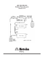
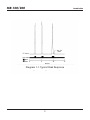
MR-100/MR-200
HPLC
Mobile Phase
Recycler
User Manual
U.S.A. 800-727-6768
www.metrohmusa.com
Email: [email protected]
MR-100/MR-200
Mobile Phase Recycler
Version 0.3
I
Warranty Statement
METROHM USA PRODUCT WARRANTY
Metrohm USA, Inc. warrants this product to be free of manufacturing defects and free of material defects
for a period of one year from the date of delivery of the product, when used in accordance with the
instructions for the product. The liability of Metrohm USA, Inc. is limited to the replacement or repair of
this product, at Metrohm USA’s sole discretion and determination.
METROHM USA, INC. MAKES NO OTHER WARRANTY, EXPRESSED OR IMPLIED. THERE IS ABSOLUTELY
NO IMPLIED WARRANTY OF MERCHANTABILITY OR FITNESS FOR A PARTICULAR PURPOSE. WARRANTY
COVERAGE APPLIES TO REPAIR OR REPLACEMENT OF THIS PRODUCT ONLY AND SPECIFICALLY EXCLUDES
ANY DIRECT, INCIDENTAL OR CONSEQUENTIAL DAMAGES.
Excluded from any product warranty claim is any and all product damage resulting from carelessness or
misuse of this product including, but not limited to, operating the product in the presence of corrosive
materials or an environment which can damage the components. Also excluded from product warranty
are all consumables/disposables.
All service and warranty returns require a return authorization number (RMA #). Please contact Metrohm
USA customer service at (800) 727-6768 for assistance or to obtain an RMA #. Return units must be sent
with proper return authorization number to:
Metrohm USA, Inc.
6555 Pelican Creek Circle
Riverview, FL 33578
RMA #:
II
MR-100/200 Mobile Phase Recycler
TABLE OF CONTENTS
1.0 Description.......................................................................................................................................................1
1.1 Specifications............................................................................................................................................4
2.0 Unpacking the instrument...............................................................................................................................5
3.0 Installation and Rear Panel Connection Guide.............................................................................................6
3.1 Fluid Connections.....................................................................................................................................7
3.2 Analog Input Connection........................................................................................................................8
3.2.1 Single Ended Input........................................................................................................................8
3.2.2 Differential Input..........................................................................................................................9
3.2.3 4-20 mA Input Connection...........................................................................................................9
3.3 Remote Control Connections................................................................................................................10
4.0 Front Panel Controls and Operation............................................................................................................12
4.1 Control Software Flowchart..................................................................................................................13
4.2 Menu System and Function Keys...........................................................................................................14
4.3 Manual Mode.........................................................................................................................................14
4.4 Setup Mode............................................................................................................................................15
4.5 Auto Mode.............................................................................................................................................17
4.6 Remote Mode.........................................................................................................................................17
5.0 MR-200 Serial Mode......................................................................................................................................18
5.1 Serial Port Interface...............................................................................................................................18
5.2 Serial Mode Command Set....................................................................................................................18
6.0 Replacement and Spare Parts........................................................................................................................20
INDEX....................................................................................................................................................................21
III
MR-100/200
Introduction
1.0 Description
The Brinkmann MR-100 mobile phase recycler is a microprocessor controlled three-way valve designed to
automatically separate uncontaminated mobile phase from contaminated solvent in an LC system. This is
done by diverting mobile phase that carries chromatographic peaks into a waste container while allowing
uncontaminated effluent to recycle back to the mobile phase reservoir.
The Brinkmann MR-100 Mobile Phase Recycler is designed to endure the laboratory environment and its
low voltage design minimizes electrical hazards. All valve wetted parts are constructed of chemically inert
and biocompatible materials and the instrument’s membrane keypad protects the unit from accidental
solvent and chemical spills. Installation is accomplished in minutes and solvent savings begin immediately.
1
MR-100/200
Introduction
The MR-100 has an analog input for connection to the system detector. The recycler has three input
ranges; 1000mV, 100mV and 10mV. Normally the valve is off and clean solvent flows through the valve
back to the mobile phase reservoir. When the analog input exceeds a user programmable threshold the
valve diverts the stream to a waste container. The valve remains in the waste position for a user defined
delay period (up to 99 seconds) to assure that tailing peaks and the volume of sample between the
detector and the recycler valve are also sent to waste.
The MR-100 recognizes both positive and negative peaks and features a bi-polar threshold so that all
peaks are sent to waste. Diagram 1-1 shows a typical chromatogram and the valve’s position throughout
the run.
The MR-100 has three modes of operation:
Auto Mode allows you to automatically recycle mobile phase by switching valve position based on
the output of your detector as described above.
Manual Mode is meant for system setup and manual control of the valve position. It lets you toggle
the valve position through the keypad.
Remote Mode lets you control the valve through an external contact closure.
At any time you can easily zero the detector output through a dedicated key on the front panel of
the MR-100 or via contact closure switch on the back panel. System setup is easy to handle with the
system LCD display and three function keys. The MR-100 walks you through every step with easy to
understand menus.
The Brinkmann MR-200 recycler gives you all the functionality of the MR-100 plus the added benefit of
remote control through an external RS-232 port. See section 5.0 for more information regarding serial
control of the recycler.
2
MR-100/200
Introduction
Diagram 1-1. Typical Peak Response
3
MR-100/200
Introduction
1.1 Specifications
Power:
12VDC 500mA maximum provided by wall mount adapter
120V, 60 Hz AC applications use PN 022859871
220VAC, 50 Hz applications use PN 022859935
Display:
2 line 20 character LCD
Valve:
Three-way 12V solenoid type
All wetted parts Teflon or PPS
1/4-28 flat bottom fluid connections
Vacuum to 30psia pressure rating
20 millisecond switching speed
250 ml/min max flow rate
Analog Input:
User selectable ranges: 1000mV, 100mV and 10mV
Input impedance 100Kohm
Auto zero:
Single key operation and/or remote input
A/D conversion:
12 bits
75Hz sample rate
Remote Inputs:
Valve position via contact closure
Auto zero via contact closure
Dimensions:
3.3” x 7.0” x 9.25” (HxWxD)
Weight:
4 lb.
4
MR-100/200
Unpacking
2.0 Unpacking the Instrument
Carefully remove the Brinkmann Mobile Phase Recycler and its accessories from the shipping carton. Save
the packing materials for future shipment and/or storage. Check to see that the package contains all of
the following items.
Contents:
1
1
1
2
4
4
1
1
1
MR-100 or MR-200 Mobile Phase Recycler
12 VDC Wall Mount Adapter rated for the voltage used in your area.
If you receive an adapter not rated for the voltage in your area please
contact Brinkmann immediately at (800) 727-6768. 120V, 60 Hz applications
use PN 022859871, 220V, 50 Hz applications use PN 022859935.
Tubing, 0.020”ID x 0.064”OD, length 4 feet (PN 022859145)
Tubing, 0.032”ID x 0.064”OD, length 5 feet (PN 022859951)
Flangeless ferrules (PN 022859986) for 0.064”OD tubing
Ferrule nuts (PN 022859978) for 0.064”OD tubing
Recycler hook-up wire, three cable, length 4 feet (PN 022859927)
Hook-up jumper (PN 022859293)
MR-100/MR-200 User manual (PN 022859994)
The following item is supplied only with the MR-200 Mobile Phase Recycler.
1
RS-232 Serial Connector Cable (PN 022860038), not included with MR-100
If any of the items are missing or appear to have suffered shipping damage, please do not attempt
to use the recycler. Contact the Metrohm USA customer service department at (800) 727-6768 for
assistance. All items returned for repair/replacement must be accompanied by a return authorization
number. If you must return any item(s) to Metrohm USA please contact customer service to receive the
proper return authorization.
5
MR-100/200
Installation
3.0 Installation and Rear Panel Connection Guide
After unpacking the MR-100, take a few minutes to check the instrument before turning it on. Check the
AC voltage rating of the wall mount adapter that accompanies the instrument (on the adapter label).
Make sure the AC voltage rating is correct for your area. If the rating is not correct do not attempt to
use the MR-100. For assistance contact the Metrohm USA service department at (800) 727-6768.
Plug the wall mount adapter into the power jack marked “POWER 12VDC.” Once you have plugged
the MR-100 wall mount adapter into a suitable AC power source turn the instrument on by pressing the
“ON/STBY” key on the front panel. The contrast level of the LCD display can be adjusted with a small
screwdriver inserted into the hole marked “DISPLAY ADJUST.” Be careful not to use excessive force when
making display adjustments. The total adjustment range is 3/4 turn.
The connector marked RS-232 option is used only on the Brinkmann MR-200 recycler (see section 5.0 for
serial command procedure).
6
MR-100/200
Installation
3.1 Fluid Connections
After unpacking The three-way valve is mounted on the rear panel. All fluid connections use standard
1/4-28 flat bottomed fittings. Four nuts (PN 022859978) and four ferrules (PN 022859986) for 1/16” OD
tubing connections are provided with the instrument as is required tubing.
Warning!!! Do not use excessive force when making fluid connections as this may strip the threads in
the valve body.
Attach a ferrule and nut to one end of both of the five foot lengths of 0.032” ID tubing (PN 022859951)
and connect these tubes to the valve ports labeled “WASTE” and “RECYCLE.” Cut these tubes to the
shortest practical length so that the open end of each can be inserted into their respective reservoirs. The
larger ID tubing (0.032”) is used on the valve outlets to prevent a pressure buildup across the valve.
Cut the 0.020” ID tubing (PN 022859145) to the length required to cover the distance between your
system’s detector and the recycler valve. The length of this tube should be minimized to reduce the dead
volume between the detector and recycler. Leave a small amount of excess tubing so that the system’s
components can be moved or rearranged without disconnecting the tube.
Attach a ferrule (PN 022859986) and nut (PN 022859978) to both ends of the tube. Connect one
end of this tube to your HPLC detector’s output line and the other to the recycler valve port labeled
“DETECTOR.”
In summary, the three ports of the recycler valve are plumbed in the following manner.
Detector
Connect the output line of the system detector here. Use the
0.020” ID tubing (PN 022859145)
Waste
Route this line to a suitable waste container. Use the
0.032” ID tubing (PN 022859951).
Recycle
Route this line back to the mobile phase reservoir or a reservoir for collecting recycled mobile phase. Use the 0.032” ID tubing
(PN 022859951).
7
MR-100/200
Installation
3.2 Analog Input Connection
Note:
The MR-100 uses an isolated wall mount adapter to supply power to the system.
This means there is no direct connection to earth ground other than the connections to the
terminal block on the MR-100 rear panel. It is important that you make a suitable ground
connection to the position marked “GND” in order for proper operation of the instrument.
The analog input of the MR-100 can accommodate three input ranges; 1000mV, 100mV and 10mV. You
set the input range through the front panel controls. This is described in section 4.0, Operation and Front
Panel Controls.
There are three methods for making connections to the analog input of the MR-100. In order of
complexity, these are Single Ended, Differential and 4-20mA.
A hook-up wire (PN 022859927) capable of either single ended or differential connection is included with
the unit, as is the jumper (PN022859293) required for single ended connections. A hook-up cable for 4-20
mAmp connections is available from Metrohm USA. Please contact Metrohm USA customer service at
(800) 727-6768 for pricing and availability.
3.2.1 Single Ended analog outputs use ground as the low side of the signal. If you are using a two wire
connection to your detector it is likely to be a single ended configuration.
Single Ended Analog Connection
It is important that you tie the “GND” and “Signal-” together in single ended applications to ensure the
MR-100 has a proper ground reference. A jumper wire (PN 022859293) is included with the system and
should be used, as shown in the figure above, to tie the “GND” and “Signal-” together.
8
MR-100/200
Installation
3.2.2 Differential analog outputs are used for better noise performance over single ended systems. A
differential configuration uses three wires and the ground jumper is not required.
Connect the third wire of the hook-up cable between the detector ground and the recycler ground. Then
route the signal outputs of the detector to the (+) and (-) inputs of the MR-100. This isolates ground
related noise from the signal source. The MR-100 will allow up to a +/-10V difference between the GND
and signal levels when wired this way.
Differential Input Analog Connection
3.2.2 4-20mA analog outputs can also be used with the MR-100. Since the MR-100 analog input is voltage
driven you must first convert the detector output current to a suitable voltage range. You can do this by
wiring the input as shown below.
4-20mA Current Loop Connection
The 62.5 ohm resistor is used to convert the 4-20mA detector output into a 1000mV full scale voltage
signal. The offset of the signal will be 4mA * 62.5 ohms=250mV. You can easily reconcile the zero level
by using the auto-zero function described in section 4.0. For 0-20mA current loops substitute a 50 ohm
resistor in place of the 62.5 ohm value.
9
MR-100/200
Installation
Once you have made the electrical connection between the detector and recycler, equilibrate the
LC system and zero the LC detector. After you have adjusted your detector zero perform an auto zero
at the recycler as described in section 4.0. This process establishes a common electrical zero point for
the detector and recycler. Once set, the recycler will automatically return to zero when the detector
is zeroed.
3.3 Remote Control Connection
There are two inputs dedicated to remote control of the MR-100 recycler. The “ZERO” input can be
used at any time to auto zero to the analog input signal via an external signal. With the recycler in the
REMOTE mode, as described in section 4.6, you can use the “REMOTE” input to control the valve position.
Both signals can be driven by either contact closures or TTL level input signals.
For contact closures applications connect the contact closure wire to the appropriate input terminal on
the back panel of the recycler. The remote input terminals are clearly marked “Remote Switch Closure”
and “Zero Switch Closure.” Hook-up wires (PN 910013050) for contact closure are available from
Metrohm USA. Please contact Metrohm USA customer service for pricing and availability.
10
MR-100/200
Installation
You can also use TTL inputs, but the signals must be referenced to ground. The proper connection is
shown below.
11
MR-100/200
Operation
4.0 Front Panel Controls and Operation
The MR-100 recycler front panel is designed to be convenient and easy to use. The operation of the
instrument centers around a 2 line 20 character LCD display. Three dedicated keys to the right of the
display can be used at any time.
ON/Stdby lets you turn the system on and off. When not in use, the MR-100 is in standby mode. Since
the power requirements of the recycler are low the internal circuitry remains powered whenever the wall mount adapter is plugged in. When in standby, the recycler valve is de-energized (in waste position) and the display is blanked.
ZERO is used to initiate an auto-zero. You must press it twice to perform the zeroing function. The double key press is to prevent inadvertent auto zeroing of the input signal. The auto zero function
will automatically trim out any offset on the input signal. Once zeroed the display will show the current input signal as 0mV and all subsequent measurements will be made relative to the new zero point. The zero input on the back panel can also be used to perform this same function through an external contact closure.
EXIT lets you abort the current operational mode or menu item. The “EXIT” key allows you to escape the portion of the software you are currently in and will take you to the next highest level of the software. The “EXIT” button will eventually lead you all the way back to the top level menu.
12
MR-100/200
Operation
4.1 Control Software Flow Chart
The flow chart below outlines the various display prompts and their relationship to each other. Please
refer back to this diagram as you read through section 4 and set up your recycler.
13
MR-100/200
Operation
4.2 Menu System and Function Keys
When you first turn the recycler on, the display briefly shows the sign-on screen along with the current
software revision number.
BRINKMANN RECYCLER
VERSION 1.00
After a few seconds the top level menu is displayed. This menu is used to start one of the four functional
modes of the instrument; Manual, Remote, Auto and Setup. The three function keys (labeled “A,” “B”
and “C”) below the display are defined by the contents of the second line of the display. You will notice
that as you use the menu system the function keys change purpose to meet the needs of the current
menu. The first display of the top level menu looks like this:
UP
- MANUAL MODE DOWN
SELECT
By pressing the function keys marked UP and DOWN you can scroll through the four modes on the top
line of the display. Press SELECT to enter the mode of your choice.
4.3 Manual Mode
Manual Mode is the simplest of the three operational modes in the recycler. Once selected, manual mode
changes the display to the following:
DS:+000mV VP:RECYCL
WASTE RECYCLE EXIT
The top line of the display shows the current input voltage and valve position. The input range and
display units can be changed through the Setup Mode. The manual mode always uses the input range
and display units of the most recently selected setup (see section 4.4).
You can use the function keys, (A) for waste and (B) for recycle, to manually change valve position. To
leave manual mode press “EXIT.” The valve position always returns to the WASTE position when you exit
a mode and re-enter the menu system.
14
MR-100/200
Operation
4.4 Setup Mode
The Setup Mode is used to program and change the parameters of each of the ten Auto Modes. To
program one of the Auto Modes enter the Setup Mode and Select one of the modes (1 to 10). The
parameters you enter in this Setup Mode will become the parameters of the Auto Mode with the
corresponding number, e.g. Setup Mode 2 will set parameters for Auto Mode 2.
The MR-100 has storage for ten individual setups. Upon entering the Setup Mode the display will show
the following:
UP
SETUP MODE:1
DOWN
SELECT
Use the function keys to select one of the ten storage locations. Once you have selected one of the ten
locations the recycler will present a menu of settings; THRESHOLD, DELAY, TIME, INPUT VOLTAGE and
SIGNAL LABEL.
UP
- THRESHOLD DOWN
SELECT
You can scroll through these settings using the up (A) and down (B) keys in the same manner as scrolling
through the modes in the top level menu. To adjust a setting you must first select it from the menu.
Remember that at any time you can use the dedicated EXIT key to return to the top level menu for
selecting modes.
THRESHOLD can be set from 0.1% to 99.9%. The threshold is set as a percentage of the full scale range.
For example, if your input range is 10mV and you set the threshold to 0.5%, the valve will go to the
waste position when the detector output exceeds 50 microvolts. The display for setting the threshold
looks like this:
THRESHOLD TH:00.5%
INC
DEC
SELECT
The proper threshold setting must be determined for each application.
15
MR-100/200
Operation
DELAY TIME has a range of 0 to 99 seconds. You use this setting to divert tailing peaks to waste. Delay
time is also used to compensate for the time it takes the sample to traverse the plumbing volume
between the detector and recycler. The default setting is 30 seconds and should be adequate for most
applications.
Several factors must be considered when selecting a delay time. Most important are the presence of
tailing peaks in your chromatogram, the dead volume of the tubing between the detector and recycler,
and the flow rate being used. The following equation can be used to calculate the time required to clear
the dead volume between the detector and recycler (assuming 0.020” ID tubing is used):
Delay (seconds) = 0.12 x tube length (cm)/flow rate (ml/min)
The display for setting the delay time is shown below:
DELAY TIME DT:00SEC
INC
DEC
SELECT
INPUT VOLTAGE range is also a setup parameter. You have a choice of three settings: 1000mV, 100mV
and 10mV. Make sure the input range you select matches the output specification for your detector. For
current loop applications, 4-20mA or 0-20mA, use an input voltage setting of 1000mV (see section 3.2.3).
The input voltage range adjustment display looks like this:
INPUT VOLTAGE 1000mV
UP
DOWN
SELECT
SIGNAL LABEL allows you to customize the display for your application. Your label choices are; mV, Au
and %. When you select mV as a label the display will show the voltage at the analog input directly.
When % is selected the display will show the input as a percent of the full scale range. By selecting Au the
display will show absorption units by assuming a full scale value corresponds to 1.000Au. As an example,
if your input voltage range was 1000mV and the input signal 500mV then the Detector Signal will be
displayed as follows:
mV.................... DS:+500mV
Au..................... DS:0.500Au
%...................... DS:+50.0%
The signal label adjustment display shows the following:
UP
SIGNAL LABEL: mV
DOWN
SELECT
16
MR-100/200
Operation
4.5 Auto Mode
The Auto Mode is the normal mode of operation for the recycler. This mode automatically controls the
valve state based upon the input signal from the detector.
Normally the valve is off and clean solvent flows through the valve back to the mobile phase reservoir.
When the analog input exceeds a user programmable threshold the valve diverts the stream to a waste
container. The valve remains in the waste position for a user defined delay period (up to 99 seconds) to
assure that tailing peaks and the volume of sample between the detector and the recycler valve are also
sent to waste. Diagram 1-1 on page 3 shows a typical peak response.
When you want to change input range, display units, signal threshold or delay time you use the Setup
Mode (see section 4.4). The MR-100 has storage for ten individual setups. When auto mode is activated
you first choose one of the ten setups. The display will show the following:
UP
AUTO MODE: 1
DOWN
SELECT
Once started the auto mode displays:
DS: +000mV VP:RECYCL
TH: 1.0% DT: 30 SEC
The top line of the display shows the current input voltage and valve position. The bottom line shows the
current threshold and delay time settings. At any time during the auto mode operation you can perform
an auto zero by pressing the ZERO key twice. To stop the auto mode press the EXIT key. When you leave
the auto mode the valve automatically returns to the WASTE position.
4.6 Remote Mode
Remote Mode lets you control the valve through an external contact closure. The operation is very simple.
The valve position follows the remote input (see section 3.3). When the contact closure is open the valve
is in the WASTE position. When the contact closure closes, the valve switches to the RECYCLE position.
During remote mode operation the display shows the following:
DS: +000mV VP:RECYCL
- REMOTE-
17
MR-100/200
MR-200 Serial Mode
5.0 MR-200 Serial Mode
5.1 Serial Port Interface
The MR-200 recycler has an RS-232 serial port located on the back panel of the unit. A serial connector
(PN 022860038) is included with the MR-200. The connector is a standard DB-9 connector used on PC’s and
other laboratory equipment. The pinouts for the connector are shown below.
Pins 1,6 and 4........................................ connected
Pins 7 and 8........................................... connected
Pin 5............................................................ ground
Pin 2................................... data from recycler (tx)
Pin 3........................................ data to recycler (rx)
The pinouts have been defined so that a “straight through” DB-9 M/F cable can be used to connect the
MR-200 to a personal computer. The communication settings of the MR-200 are fixed at 9600 baud, no
parity, eight data bits and 1 stop bit.
5.2 Serial Mode Command Set
The command set of the MR-200 serial mode is based on ASCII characters. The MR-200 will automatically
enter the serial mode when it receives any characters at the serial port. The commands available give full
control over the state of the recycler.
Wx
N
F
V
Controls state of the recycler valve.
x = 0 for return standalone operations (exits to mode selection menu)
x = 1 for serial control of valve position
x = 2 for valve to follow remote input contact closure
x = 3 for valve to follow threshold/delay time settings
Valve to recycle position (only used after W1 command)
Valve to waste position (only used after W1 command)
Returns the equipment type and version number.
Response: Vxy
x = equipment number, always 2 for MR-200
y = version number (x.xx)
18
MR-100/200
MR-200 Serial Mode
Rxx
Sets the Range
xx = 00 for +/-10mV
xx = 01 for +/-100mV
xx = 02 for +/-1000mV
Uxx
Sets the displayed system units.
xx = 00 for mV
xx = 01 for Au
xx = 02 for %FS
ZO
Auto-zeroes the input signal level
Hxxx Sets the threshold value in %FS. (only active after W3 command)
xxx = 001 through 999 for 00.1% to 99.9% threshold
Txx
Sets the delay time. (only active after W3 command)
xx = 00 to 99 seconds
Cx
Enable/Disable chart recorder data
1 = enable
0 = disable
When chart recorder data is enabled the MR-200 will send a “P” command every second.
D0
Prompts the MR-200 to return a single data value via the serial port.
Pxy
The data point command “P” is sent from the MR-200.
x = status, see S command
y = three digit data plus sign without decimal point
Example: +005 is .005Au when Au is the selected unit.
S0
Requests a Return Status indicator which is sent to the host computer. The MR-200 will send a S0
or S4. Lower bits are reserved for future use in peak detection.
S0 = valve to recycle
S4 = valve to waste
E
Returned when invalid command received
19
MR-100/200
Replacement Parts
6.0 Replacement and Spare Parts List
The following parts and accessories are available for the MR-100 and MR-200 Mobile Phase Recyclers.
Contents:
Part
2 VDC Wall Mount Adapter
120V applications
220V, 50 Hz applications
Tubing, 0.020”ID x 0.064”OD, length 4 feet
Tubing, 0.032”ID x 0.064”OD, length 5 feet
Flangeless ferrules (qty 4)
Ferrule nuts (qty 4)
3 Cable hook-up wire, length 4 feet
Hook-up jumper
Three-way valve
MR-100/MR-200 User Manua
Part Number
022859871
022859935
022859145
022859951
022859986
022859978
022859927
022859293
910012967
022859994
RS-232 Serial Connector Cable, for MR-200
022860038
Conact Metrohm USA customer service at (800) 727-6768 for pricing and availability. Please contact the
Metrohm USA service department if you have any questions regarding the service and/or operation of
your recycler.
All units returned for repair/replacement must be accompanied by a return authorization number
(RMA#). Contact Metrohm USA customer serivce at (800) 727-6768 to obtain return instructions and
proper return authorization.
20
MR-100/200
Index
INDEX
AC voltage rating, 4, 5, 6
analog input, 4, 8
0-20mA, 9
4-20mA, 9
differential, 9
single ended, 8
auto mode, 2, 17
auto-zero, 4, 10, 12
delay time, 16
display, 6, 12
display adjustments, 6
earth ground, 8
EXIT key, 12
fluid connections, 7
function keys, 14
input voltage, 4, 16
LCD display, 6, 12
manual mode, 2, 14
ON/Stdby key, 12
power jack, 6
remote input, 2, 4, 10
remote mode, 2, 17, 18
RS-232, 2, 18, 20
21
MR-100/200
Index
INDEX
setup mode, 15
signal label, 16
software revision number, 14
specifications, 4
standby, 12
three-way valve, 1, 4, 7
threshold, 2, 15
top level menu, 12, 14, 15
unpacking the MR-100, 5
valve, 1, 4, 7
wall mount adapter, 4, 5, 6
ZERO key, 12
zeroing detector input, 4, 10, 11, 12
22