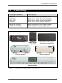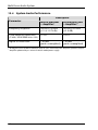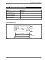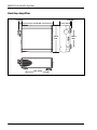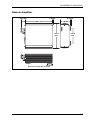
1
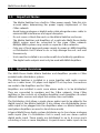
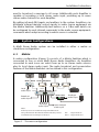
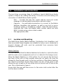
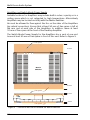
Multi Room Audio System
Installation Instructions
560011
560125D
560125R
560884
POWER
Distribution Unit
Desktop Amplifier
Remote Amplifier
Matrix Switcher
MUTE
ZONES
1
2
3
4
5
6
7
8
AUDIO R
AUDIO L
IR
DIGITAL
AUDIO
OUTPUT
DC 24V
INPUT
POWER
© Copyright Clipsal Integrated Systems Pty Ltd 2005. All rights reserved. This
material is copyright under Australian and international laws. Except as permitted
under the relevant law, no part of this work may be reproduced by any process
without prior written permission of and acknowledgement to Clipsal Integrated
Systems Pty Ltd.
Clipsal is a registered trademark of Clipsal Australia Pty Ltd.
The information in this manual is provided in good faith. Whilst Clipsal Integrated
Systems (CIS) has endeavoured to ensure the relevance and accuracy of the
information, it assumes no responsibility for any loss incurred as a result of its use.
CIS does not warrant that the information is fit for any particular purpose, nor does
it endorse its use in applications which are critical to the health or life of any
human being. CIS reserves the right to update the information at any time without
notice.
V1.0 Dec 2005
Contents
1.0
Product Range
5
2.0
Important Notes
6
3.0
System Overview
6
4.0
System Configurations
7
5.0
4.1
Matrix
7
4.2
Standalone
8
Installation and Connection
9
9
5.1
Location and Mounting
5.2
An Example System
11
5.3
C-Bus Cabling
12
5.4
Speaker Cabling
14
5.5
Digital Audio Cabling
16
5.6
IR Target Cabling
18
5.7
Shielded Audio Cabling
20
5.8
Connecting Multi Room Audio Units 22
6.0
C-Bus System Clock
25
7.0
C-Bus Network Burden
25
8.0
C-Bus Power Requirements
26
9.0
Power Surges
26
Programming and Setup
27
10.0
10.1
C-Bus Toolkit
28
10.2
MARPA
44
Multi Room Audio System
11.0
4
Unit Connections
53
11.1
Distribution Unit
53
11.2
Amplifiers
54
11.3
Matrix Switcher
57
12.0
Troubleshooting
60
13.0
Electrical Specifications
62
13.1
Distribution Unit
62
13.2
Matrix Switcher
62
13.3
Amplifiers
63
13.4
System Audio Performance
64
14.0
Mechanical Specifications
65
15.0
Standards Complied
69
16.0
Warranty
70
Installation Instructions
1.0
Product Range
Catalogue Number
Description
560011
560125D
560125R
560884
Multi Room Audio Distribution Unit
Multi Room Audio Desktop Amplifier
Multi Room Audio Remote Amplifier
Multi Room Audio Matrix Switcher
5600P24/500AU
5600P24/3750AU
MRA Distribution Unit Power Supply
MRA Amplifier Power Supply Unit
AUDIO R
IR
AUDIO L
DIGITAL
AUDIO
OUTPUT
DC 24V
INPUT
POWER
Distribution Unit (DU)
POWER
Switch Mode Power Supply
Unit (PSU) for Amplifiers
Power Supply
(PS) for DU
MUTE
Desktop Amplifer
Remote Amplifier
ZONES
1
2
3
4
5
6
7
8
Matrix Switcher
Figure 1 – Multi Room Audio product identification
5
Multi Room Audio System
2.0
•
•
•
•
•
•
•
3.0
Important Notes
The Matrix Switcher has a built-in C-Bus power supply. Take this into
account when determining the power supply requirement of the
C-Bus network.
Avoid laying analogue or digital audio cable alongside mains cable, to
minimise EMI interference and signal disruption.
Do not cover or block the vents on the Matrix Switcher enclosure.
The Matrix Switcher and Amplifiers of a particular Multi Room Audio
(MRA) system must be connected to the same C-Bus network.
Multiple MRA systems may reside on separate C-Bus networks.
Only use a Clipsal approved power supply to power an MRA Amplifier
or Distribution Unit. Failure to do so may damage the unit, and void
the warranty.
Units must be installed in accordance with local authority guidelines.
The digital audio outputs must only be used with MRA Amplifiers.
System Overview
The Multi Room Audio Matrix Switcher and Amplifiers provide a C-Bus
enabled audio distribution system.
The Matrix Switcher is installed in a room together with audio sources
such as a radio tuner, CD player and digital TV set top box. Connections
are made to the Amplifiers and to C-Bus.
Amplifiers are installed in each room where audio is to be distributed.
They are connected to speakers and the C-Bus network. Using C-Bus
switches (or the controls on a Desktop Amplifier), each Amplifier can select
different audio sources and adjust the volume, bass and treble.
The Distribution Unit allows a single stereo audio input to be added to the
digital input of the Matrix Switcher. It also allows one distributable stereo
audio input to be plugged into the Amplifiers when no Matrix Switcher is
used (when Amplifiers are used in stand-alone mode).
A typical Multi Room Audio system distributes up to four stereo analogue
audio inputs (five if a Distribution Unit is used), and one stereo optical
digital audio input. These inputs are distributed to up to 8 zones (each
consisting of one or more Amplifiers). A special mono audio input can be
6
Installation Instructions
used to broadcast a message to all zones. Additionally each Amplifier is
capable of accepting a local stereo audio input, providing up to seven
stereo audio channels for each Amplifier.
By adding infrared (IR) targets and emitters to the system, Amplifiers can
distribute infrared remote control signals to audio source equipment via
the Matrix Switcher. Additionally two buttons on a C-Bus wall switch can
be configured to send infrared commands to the audio source equipment;
commands which adapt according to which source is selected.
4.0
System Configurations
A Multi Room Audio system can be installed in either a matrix or
standalone configuration.
4.1
Matrix
A matrix configuration (Figure 2) consists of a Matrix Switcher which is
connected to one or more Multi Room Audio Amplifiers. An Amplifier
connected to each zone can select from up to six stereo audio sources
plus its local stereo audio input. The audio broadcast and annunciation
features of the Matrix Switcher can be utilised in this configuration.
Multi
POWER
Room
Audio
Amplifiers
MUTE
DIn
Local
audio input
DIn
DOut
DIn
DIn
PSU
DOut
Matrix Switcher DOut
DOut
ZONES
1
2
3
4
5
6
7
8
Analogue
audio input
DIn Distr’n Unit
Broadcast
audio input
AUDIO R
AUDIO L
IR
DIGITAL
AUDIO
OUTPUT
DC 24V
INPUT
Analogue
audio inputs
POWER
PS
Optical digital
audio input
Notes:
Audio inputs are stereo with the exception of Broadcast.
Using a Distribution Unit with the Matrix Switcher provides
an additional stereo analogue audio input.
DIn – Digital Audio In
DOut – Digital Audio Out
Figure 2 – The matrix confguration
7
Multi Room Audio System
4.2
Standalone
In a standalone configuration a stereo audio source is connected to the
input of a Distribution Unit. The output of the Distribution Unit is
connected to the digital input of each Amplifier. RJ45 splitters are used to
connect all digital inputs to a common Cat-5 cable run. A Matrix Switcher
is not used. Up to eight Amplifiers can be connected in this mode using a
total cable length of up to 45 m. This is illustrated in Figure 3. Each
Amplifier can select between the single distributed stereo audio source
and its local stereo audio input.
Multi
Distr’n Unit
Analogue
audio input
AUDIO R
AUDIO L
IR
POWER
DIn
Room
Audio
MUTE
P
DIn
P
DIn
P
LIn
DIGITAL
AUDIO
OUTPUT
DC 24V
INPUT
POWER
PSU
PSU
Notes:
Audio inputs are stereo.
Do not connect a Power Supply to the Distribution Unit
when it is connected to an Amplifier’s Digital Input. In this
configuration, the Distribution Unit receives its power
from the Amplifier.
Figure 3 – Standalone configuration
8
Amplifiers
PSU
Local
audio
input
DIn – Digital Audio In
LIn – Local In
P
– Power input
Installation Instructions
5.0
Installation and Connection
The most time consuming stage of installing a typical Multi Room Audio
system is likely to be cabling and wiring. To ensure successful wiring and
connection of a Multi Room Audio system:
•
•
•
5.1
Plan – Consider the way the system will be used and create
drawings to indicate where terminations will be located.
Organise – Use wall plate terminations to connect to the Matrix
Switcher, Amplifiers and speakers, as well as any local or mono
broadcast inputs or headphone outputs. Label the terminations,
especially the C-Bus and digital audio sockets which are both
RJ45. Consider using colour coded sockets.
Use appropriate cable.
Location and Mounting
The Multi Room Audio Matrix Switcher, Distribution Unit, Amplifiers and
their associated Power Supplies are suitable for indoor use in moderate to
tropical climates. All units must be protected from excessive heat,
dampness and liquids.
Matrix Switcher
It is recommended that the Matrix Switcher be located in a central location
with the audio source equipment (such as in a cabinet in the lounge room).
Place the Matrix Switcher on a flat surface. Do not remove the feet from
the base of the unit as they provide necessary air space. Air must be
allowed to flow through vents on the top and base of the Matrix Switcher
(by natural convection). Ensure that at least 15 mm of free space is left
above the unit, as well as 50 mm at the front of the unit and 75 mm at the
rear. This is illustrated in Figure 4.
Ensure that the user will have access to the mains inlet socket after the
unit has been installed.
9
Multi Room Audio System
Amplifiers and Switch Mode Power Supply
Suitable locations for Amplifiers may include built-in robes, a pantry or in a
ceiling space which is not subjected to high temperature. Alternatively
Amplifiers may be located centrally with the Matrix Switcher.
Air must be allowed to flow against the fins on the sides of the Amplifiers
(by natural convection). Ensure that at least 50 mm of free space is left at
the rear and at each side of the Amplifiers. In addition, leave at least
10 mm of free space at the front of the Desktop Amplifier.
The Switch Mode Power Supply for the Amplifiers has a vent at one end.
Leave at least 50 mm of free space in front of this vent. Refer to Figure 5.
free space
75 mm
Matrix
Switcher
50 mm
free space
15 mm
ZONES
1
2
3
4
5
6
7
8
8 mm
free space
Figure 4 – Clearance must be left around the Matrix Switcher
10
Installation Instructions
free space
free space
50 mm
air vent
Amplifier
free space
10 mm
Switchmode
Power Supply
for Amplifiers
free space
POWER
MUTE
50 mm
50 mm
Figure 5 – Clearance must be left around Amplifiers and their Power Supplies
5.2
An Example System
In a Multi Room Audio (MRA) installation, you can locate an Amplifier and
speakers in each room where audio is required. You would then run RJ45
cable across the building from the Matrix Switcher to each Amplifier, and
run shorter lengths of cable from the Amplifiers to the speakers.
Alternatively, you can locate all Amplifiers in a central location and run the
speaker cables across the building. In the example used to illustrate an
MRA system installation, a combination of these methods is used.
The example system consists of one Matrix Switcher, five Remote
Amplifiers and one Desktop Amplifier. Three of the Remote Amplifiers are
collocated with the Matrix Switcher. One Remote Amplifier is located on a
shelf in the Garage and another in a built-in robe (BIR). The Desktop
Amplifier is located on a desk in Bedroom 2 (BR2). Speakers are mounted
on walls using appropriate brackets. Wall plates are used in the bedrooms
and family room to provide local inputs. These can be used to connect to
the audio output of a personal computer (PC) or portable audio player.
On the following pages, diagrams are used to illustrate the C-Bus, speaker,
digital audio, IR target and shielded audio stages of the installation.
11
Multi Room Audio System
5.3
C-Bus Cabling
The Amplifiers and Matrix Switcher in a Multi Room Audio system must be
connected to a common C-Bus network. Use Cat-5 Unshielded Twisted
Pair (UTP) C-Bus cable, and appropriately wired RJ45 plugs and wall plates.
Pinouts and cable conductor assignments are provided in Figure 6 and
Table 1. Label wall plates to differentiate between other RJ45 connection
types (such as Digital Audio and Ethernet). If colour coding, it is suggested
you use pink for C-Bus, green for Digital Audio and blue for Ethernet.
Use a C-Bus wall switch (such as Ulti Saturn, Neo or Reflection) to control
each zone of the Multi Room Audio system. Switches with Dynamic
Labelling Technology (DLT) can be configured to provide visual feedback
of selected audio sources. Typically, an individual C-Bus wall switch is used
to control both lighting and audio.
In the example installation in Figure 7, Ulti Saturn and Neo wall switches
are used in BR2 and BR3 respectively (zones 2 and 3), and DLT wall
switches are used to control the remaining Multi Room Audio zones.
C-Bus Positive:
blue + orange
C-Bus Negative: blue & white + orange & white
Remote OFF:
brown + brown & white
Remote ON:
green + green & white
Figure 6 – C-Bus cable conductor assignments
Pin
87654321
12345678
C-Bus Connection
1
Remote ON
green & white
2
Remote ON
green
3
C-Bus Negative (–)
orange & white
4
C-Bus Positive (+)
blue
5
C-Bus Negative (–)
blue & white
6
C-Bus Positive (+)
orange
7
Remote OFF
brown & white
8
Remote OFF
brown
Table 1 – RJ45 sockets and C-Bus Pinouts
12
Colour
Installation Instructions
L
BR3
Volume
DVD
Family
Play
Skip
(Zone 3)
next
(Zone 4)
Light
Radio
DVD
Dyn1
IR
IR
L Sw
RJ45
Sw
C
C
Vol
TV
Local
Dyn2
M C
Dining
Lounge
Volume
C
DA
IR
DVD
Play
Skip
IR
next
C Sw
Kitchen
C Sw
(Zone 5)
(Zone 6)
IR
(Zone 2)
Pantry
Patio
C
L
Sw
BIR
Volume
DVD
C
A
RJ45
BR2
Play
Skip
CA
C
next
RJ45
Sw
RJ45
Garage
IR
BR1
L
Volume
(Zone 1)
DVD
Play
Skip
Vol /
Src
Dyn1
Dyn2
next
M
Matrix Switcher, 3×MRA Amps, Source Equipment
A DA MRA Remote Amp, MRA Desktop Amp
Sw
Speaker (wall surface mounted)
IR Target (ceiling mounted)
C-Bus Cat-5 cable
L
IR
IR
C-Bus wall switch
Local Input (on wall plate)
IR Target (ceiling mounted)
C C-Bus connection point
Figure 7 – C-Bus cabling and termination
13
Multi Room Audio System
5.4
Speaker Cabling
Depending on the installation, speakers may be mounted on a wall using
brackets, or flush mounted on a wall or ceiling. When speakers are
mounted on brackets, it is recommended that an RCA wall plate is installed
adjacent to each speaker.
Spring-release or screw binding post wall plates are used to connect to
speaker outputs of the Amplifiers.
Use low impedance speaker cable to connect the binding post (Amplifier)
wall plates to the RCA (speaker) wall plates. This is especially important
with long cable runs.
Figure 8 illustrates how an RCA wall plate is used to connect a speaker.
This is ideal for speakers which have been mounted on walls using
brackets, as in the example installation in Figure 9.
Figure 8 – An RCA wall plate makes a practical speaker connection point
14
Installation Instructions
R
L
BR3
Family
(Zone 4)
(Zone 3)
RCA
RCA
IR
IR
L Sw
Sw
R
R
R
b
b
M
Mb
Lounge
Dining
RCA
R
R b
DA
IR
IR
Sw
Kitchen
Sw
(Zone 5)
Pantry
L
Sw
(Zone 6)
IR
R
b
BR2
(Zone 2)
R
RCA
Patio
R
BIR
R
A
bA
Sw
Garage
IR
R
BR1
L
(Zone 1)
RCA
R
M
Matrix Switcher, 3×MRA Amps, Source Equipment
A DA MRA Remote Amp, MRA Desktop Amp
Sw
Speaker (wall surface mounted)
IR Target (ceiling mounted)
Speaker cable
L
IR
IR
C-Bus wall switch
Local Input (on wall plate)
IR Target (ceiling mounted)
R RCA wall plate
b binding post wall plate
Figure 9 – Speaker cabling and termination
15
Multi Room Audio System
5.5
Digital Audio Cabling
A digital audio cable must be connected between each Amplifier and the
Matrix Switcher. Use Cat-5 Unshielded Twisted Pair (UTP) data cable, and
appropriately wired RJ45 plugs and wall plates.
Since Cat-5 cable may be used for several purposes within the same
installation, it is recommended you use green cable for digital audio
connections, pink for C-Bus and blue for Ethernet. Wall plates should be
labelled to differentiate between the various RJ45 connection types.
Colour coding of sockets is recommended.
Avoid laying digital audio cable alongside mains cable, as electromagnetic interference (EMI) can disrupt the signal. An individual Cat-5
cable which connects a digital audio output to an input should not exceed
45 metres. This is illustrated in Figure 10.
POWER
MUTE
45 metres
maximum
ZONES
1
2
3
4
5
6
7
8
45 metres
maximum
IR
AUDIO R
AUDIO L
DIGITAL
AUDIO
OUTPUT
DC 24V
INPUT
POWER
POWER
MUTE
Figure 10 – Maximum digital audio cable length
16
Installation Instructions
L
BR3
Family
(Zone 3)
(Zone 4)
IR
IR
L Sw
Sw
RJ45
D
D
MD
Dining
Lounge
D
Sw
Kitchen
Sw
(Zone 5)
L
Sw
(Zone 6)
IR
BR2
(Zone 2)
Pantry
Patio
RJ45
DA
IR
IR
BIR
D
A
DA
Sw
RJ45
RJ45
Garage
M
IR
BR1
L
(Zone 1)
Matrix Switcher, 3×MRA Amps, Source Equipment
A DA MRA Remote Amp, MRA Desktop Amp
Sw
Speaker (wall surface mounted)
IR Target (ceiling mounted)
Cat-5 cable
L
IR
IR
C-Bus wall switch
Local Input (on wall plate)
IR Target (ceiling mounted)
D Digital Audio wall plate
Figure 11 – Digital audio cabling and termination
17
Multi Room Audio System
5.6
IR Target Cabling
An infrared (IR) target can be connected to the green Phoenix socket on
the rear of each Amplifier. This allows an IR remote control to operate
audio source equipment which is fitted with IR emitters connected to the
Matrix Switcher. Figure 12 shows two methods of connecting an IR target
to an Amplifier.
A suitable IR target is the Clipsal 8050TT Tube Target mounted on a
ceiling or wall (optionally via a wall plate). Extend the cable if required and
wire to a 3.5 mm stereo socket on a wall plate adjacent to the Amplifier.
Up to 45 m of total cable may be used between a target and the Matrix
Switcher (or Distribution Unit in standalone mode). Create a lead to
connect the Amplifier IR input to the 3.5 mm wall plate socket.
A Clipsal 8050ST Shelf Top Target can be mounted on top of a Desktop
Amplifier and plugged directly into the IR input on its rear panel.
IR signals received by external IR targets cannot directly control
the Amplifiers. Such control is accomplished via the IR receiver
built into the front panel of the Desktop Amplifier.
wall plate with
3.5 mm stereo socket
8050TT Tube IR Target
8050ST Shelf
Top IR Target
Connection via a wall plate
Direct connection
Figure 12 – Connecting an IR target to an Amplifier
18
Installation Instructions
L
BR3
Family
(Zone 3)
(Zone 4)
IR
IR
L Sw
3.5 mm
Sw
I
I
MI
Dining
Lounge
3.5 mm
I
DA
IR
IR
Kitchen
Sw
Sw
(Zone 5)
Pantry
Patio
L
Sw
(Zone 6)
IR
BR2
(Zone 2)
BIR
I
A
3.5 mm
IA
Sw
3.5 mm
Garage
M
IR
BR1
L
(Zone 1)
Matrix Switcher, 3×MRA Amps, Source Equipment
A DA MRA Remote Amp, MRA Desktop Amp
Sw
Speaker (wall surface mounted)
IR Target (ceiling mounted)
IR Target cabling
L
Local Input (on wall plate)
I
IR Target (ceiling mounted)
IR Target connection point
(3.5 mm stereo socket)
IR
IR
C-Bus wall switch
Figure 13 – IR target cabling and termination
The example installation in Figure 13 uses ceiling mounted Clipsal 8050TT
Tube Targets for Remote and Desktop Amplifiers.
19
Multi Room Audio System
5.7
Shielded Audio Cabling
Multi Room Audio Amplifiers have line level local audio inputs (LOCAL IN),
which can be used to play audio from a locally connected music player or
PC. Amplifiers also have volume affected line level audio outputs (ZONE
OUT) which can be connected to other audio equipment. The Desktop
Amplifier has a headphone output. These inputs and outputs should be
cabled and terminated if they are to be utilised.
It is recommended that wall plates with appropriate audio sockets be used
to provide input and output connection points to the Amplifier. Use RCA
sockets at the Amplifier end for local inputs and line outputs. Use 3.5 mm
stereo sockets at the other end to provide the connection points for
external audio equipment. Use 3.5 mm stereo sockets for headphone
connections.
When installing audio cable:
•
•
•
wire wall plates with suitably shielded stereo audio cable
avoid laying audio cable alongside mains cable to minimise EMI
pickup
do not earth audio ground terminals.
Cabling and wall plate requirements for the example installation are
illustrated in Figure 14.
20
Installation Instructions
L
L
Family
BR3
3.5 mm
(Zone 4)
(Zone 3)
IR
IR
L Sw
Sw
L
R
MR
RCA
Dining
Lounge
RCA +
3.5 mm
R
DA
IR
IR
Sw
Kitchen
Sw
(Zone 5)
Patio
(Zone 6)
BR2
(Zone 2)
Pantry
3.5 mm
L
H
Sw
BIR
IR
A
RA
RCA
Sw
Garage
IR
BR1
L L
(Zone 1)
3.5 mm
M
Matrix Switcher, 3×MRA Amps, Source Equipment
A DA MRA Remote Amp, MRA Desktop Amp
IR
Speaker (wall surface mounted)
IR Target (ceiling mounted)
Speaker cable
H Headphone + Local audio input wall plate
(3.5 mm stereo socket)
Sw
C-Bus wall switch
L
IR
Local Input (on wall plate)
IR Target (ceiling mounted)
R RCA wall plate
L Local audio input wall plate
(3.5 mm stereo socket)
Figure 14 – Shielded audio (local input/headphone output) cabling & termination
21
Multi Room Audio System
5.8
Connecting Multi Room Audio Units
Once wall plate connections have been installed and cabled and speakers
have been connected, you are ready to connect the Multi Room Audio
Amplifiers and Matrix Switcher.
Figures 15 to 17 show the connection of Amplifiers for zones 1, 2 and 6 of
the example system. Figure 18 shows the connection of Amplifiers for
zones 3, 4 and 5 (which are centrally located), and for the Matrix Switcher.
Unit connections are identified on Page 53. Descriptions of the front
panels are provided in the Amplifier and Matrix Switcher User’s Guides.
Zone 1 Remote Amp (BR1)
L
R
DIGITAL
AUDIO IN
ZONE
LOCAL
OUT L
IN
EXTERNAL
IR
OPTICAL
TARGET
IN
Unit
R
POWER
Speakers - Zone 1
Local Input
DIGITAL
AUDIO OUT
IR
Digital
Audio
Z1
Z1
C-Bus
Z1
Figure 15 – Zone 1 Amplifier connections
22
Installation Instructions
Zone 2 Desktop Amp (BR2)
L
DIGITAL
AUDIO IN
R
ZONE
LOCAL
OUT L
IN
EXTERNAL
IR
OPTICAL
TARGET
IN
Unit
R
POWER
DIGITAL
AUDIO OUT
Speakers - Zone 2
IR
Digital
Audio
Z2
Z2
Local Input
C-Bus
Z2
Figure 16 – Zone 2 Desktop Amplifer connections
Zone 6 Remote Amp (Patio/Garage)
L
DIGITAL
AUDIO IN
R
ZONE
LOCAL
OUT L
IN
EXTERNAL
IR
OPTICAL
TARGET
IN
Unit
R
POWER
Speakers - Zone 6
DIGITAL
AUDIO OUT
IR
Digital
Audio
Z6
Z6
C-Bus
Figure 17 – Zone 6 Amplifier connections
23
Multi Room Audio System
L
DIGITAL
AUDIO IN
R
ZONE
LOCAL
OUT L
IN
Zone 5 Amp
(Kitchen)
EXTERNAL
IR
OPTICAL
TARGET
IN
Unit
R
POWER
DIGITAL
AUDIO OUT
L
ZONE
LOCAL
OUT L
IN
DIGITAL
AUDIO IN
R
Zone 4 Amp
(Family)
EXTERNAL
IR
OPTICAL
TARGET
IN
Unit
R
POWER
DIGITAL
AUDIO OUT
L
DIGITAL
AUDIO IN
R
ZONE
LOCAL
OUT L
IN
Zone 3 Amp
(BR3)
EXTERNAL
IR
OPTICAL
TARGET
IN
Unit
R
POWER
DIGITAL
AUDIO OUT
IR
Speakers - Zone 5
Z5
Speakers - Zone 4
Z4
Z3
Local Inputs
C-Bus
Z3
Z4
Digital Audio
Speakers - Zone 3
Z6
Z2
Z1
Only use F 3,15A L 250V fuse
1
IR OUT
SOURCE INPUT
2
DIGITAL AUDIO OUT
CAUTION: USE ONLY WITH C-Bus MULTIROOM AUDIO SYSTEM AMPLIFIERS
ZONE 8
ZONE 7
ZONE 6
ZONE 5
OUT OPTICAL IN
To IR Emitters on
source equipment
To optical
output on
source equip.
ZONE 4
ZONE 3
ZONE 2
ZONE 1
DIGITAL
AUDIO
IN
To Distribution Unit
output (provides an
extra stereo input)
1
2
3
BROADCAST
4
USB
C-Bus
L
Unit
R
To audio line outputs
on source equipment
Figure 18 – Matrix Switcher and Zone 3 to 5 Amplifier connections
24
Installation Instructions
6.0
C-Bus System Clock
The Multi Room Audio Matrix Switcher and Amplifiers incorporate a
software selectable C-Bus system clock. The system clock is used to
synchronise data communication over a C-Bus network. At least one active
C-Bus system clock is required on each C-Bus network for successful
communication. No more than three units on any C-Bus network should
have clock circuitry enabled, so this option is normally disabled using the
C-Bus Toolkit software.
If a system clock is required, it can be enabled when editing the unit in the
C-Bus Toolkit software.
7.0
C-Bus Network Burden
The Multi Room Audio Matrix Switcher and Amplifiers incorporate a
software selectable network burden. The network burden can be enabled
when editing the unit in the C-Bus Toolkit software, but only if the C-Bus
system clock is also enabled.
One network burden is normally required to ensure correct operation of
each C-Bus network. The Network window of a C-Bus Toolkit project
provides a summary of a C-Bus network according to the units added to
the Database. This can be helpful in determining how many burdens are
required on a particular network.
25
Multi Room Audio System
8.0
C-Bus Power Requirements
The Matrix Switcher has a built-in C-Bus Power Supply which provides
330 mA to the C-Bus network. Multi Room Audio Amplifiers draw 22 mA
from the C-Bus network.
The Matrix Switcher supplies enough C-Bus power for at least seven Multi
Room Audio Amplifiers and seven C-Bus wall switches (such as the Ulti
Saturn or DLT).
The Distribution Unit does not connect to C-Bus and therefore does not
impact on the power requirements of a C-Bus network.
The Network window of a C-Bus Toolkit project provides a summary of a
C-Bus network according to the units added to the Database. This can be
helpful in determining the power supply requirements of a particular
network.
9.0
Power Surges
External power surge protection devices should be used to enhance
system immunity to power surges. It is strongly recommended that
overvoltage protection equipment such as the Clipsal 970 Series be
installed at the switchboard.
26
Installation Instructions
10.0 Programming and Setup
Once a Multi Room Audio (MRA) system has been installed, it must be
configured using the C-Bus Toolkit software and the Multi Room Audio
Rapid Programming Application (MARPA).
Radio Tuner
(Audio source #1)
Infrared
DVD
(Audio source #3)
Digital Audio
Analogue Audio
C-Bus
Digital TV
(Audio source #2)
Unit
1
2
3
4
C-Bus
Dimmer
ZONES
1
IR
Target
3
2
4
6
7
8
IR
Target
POWER
Volume
Radio
Station+
Station-
Computer
(Local Input)
Vol. Up
Vol. Dn
Radio
Nxt Srce
Volume
Nxt Srce
Dyn. Ctrl 1
Dyn. Ctrl 2
Light
Radio
DVD
Volume
TV
Local
Dyn. Ctrl 1
Dyn. Ctrl 2
2
Zone 1
IR
Target
MUTE
Computer
(Local Input)
14:02
5
Zone 2
Zone 3
Figure 19 – Example system to be configured by software
27
Multi Room Audio System
It is highly recommended that you complete a C-Bus Training Course
before configuring a Clipsal Multi Room Audio system. Sections 10.1 and
10.2 take you through the configuration process. These sections assume
you are familiar with the C-Bus Toolkit software. They use the example
system shown in Figure 19. This system consists of three zones and uses
the following units (all on the same C-Bus network):
1 × Matrix Switcher
2 × Remote Amplifiers
1 × Desktop Amplifier
1 × Ulti Saturn DLT wall switch
1 × 6 button Ulti Saturn wall switch
1 × 8 button Neo wall switch
1 × radio tuner (audio source #1)
1 × digital TV set top box (audio source #2)
1 × DVD player (audio source #3)
1 × 4 Channel Dimmer.
10.1 C-Bus Toolkit
C-Bus programming is accomplished using the C-Bus Toolkit software. It
involves:
•
•
•
1)
2)
28
creating a C-Bus project with a Group Address structure which is
used by MRA Amplifiers and the MARPA software
enabling a C-Bus system clock and burden in the Matrix Switcher
(if required)
configuring each MRA Amplifier so it can be controlled by one or
more C-Bus wall switches.
Start Toolkit, and create a new C-Bus project and network for the
MRA system. If a project and network already exist (such as when you
are adding to an existing C-Bus network), open that project and
network.
Decide which Application you will use for the MRA system. You may
create a unique Application (such as “Lighting/Audio” Application
Address 55). However, if you use C-Bus wall switches to control both
lights and audio, both need to use the same Application Address. In
this case it may be best to use the default “Lighting” Application
Address 56.
Installation Instructions
3)
Create the Group Addresses. These are used to associate buttons on
wall switches or a touch screen with Amplifier control functions such
as volume and source selection. For each Amplifier, create a Group
Address for each of the following that will be controlled from a C-Bus
device:
• Volume
• Bass
• Treble
• Next Source
• Previous Source
• Absolute Source (used in combination with a selector)
• Dynamic 1
• Dynamic 2.
It is suggested you use clearly identifiable tag names/descriptions when
you create the Group Addresses. Suitable Groups for the example MRA
system in Figure 19 are shown in Figure 20.
Figure 20 – Group Addresses used in the example MRA system
29
Multi Room Audio System
4)
A button on a wall switch can be used to select a specific audio
source (absolute source). This is normally achieved by configuring the
button as a scene. If you program a C-Bus DLT wall switch to select an
absolute source, you must create a Group Address in the Trigger
Control Application and an Action Selector (selector) for each scene.
These allow you to send labels to the DLT scenes. Such a Trigger
Control Group Address with selectors is shown in Figure 21.
Figure 21 – Selectors used in DLT scenes for absolute source selection
5)
Two dynamic control buttons can be used on a wall switch to perform
different functions depending on which source is selected. If you use
dynamic control buttons you must create a Group Address in the
Trigger Control Application and a selector for each function. These
selectors are used when configuring the Matrix Switcher with the
MARPA software. A Trigger Control Group Address with selectors
used in the example MRA system is shown in Figure 22.
Figure 22 – Selectors used for the dynamic control functions
30
Installation Instructions
6)
Select the Units branch of the C-Bus Toolkit tree view and add the
C-Bus units to the network. Figure 23 shows C-Bus Toolkit after
adding the units used in the example MRA system. Added units
consist of:
1 × MRA Matrix Switcher
3 × MRA Amplifiers
3 × C-Bus wall switches
1 × DIN Rail Dimmer.
Figure 23 – Units added to the network in the MRA project
7)
Configure the Matrix Switcher unit (if necessary). The Matrix Switcher
needs to be configured in Toolkit only to enable its C-Bus system
clock or network burden. In a C-Bus network consisting entirely of
MRA devices, or where the Matrix Switcher is the only unit with a
C-Bus power supply, it is recommended that you enable the Matrix
Switcher’s C-Bus system clock and burden. This is shown in Figure 24.
Figure 24 – Enable the Matrix Switcher's C-Bus clock and burden
31
Multi Room Audio System
8)
Configure the Amplifiers. In a typical MRA system such as in Figure 19
the default settings on the Audio Levels and Zoning tabs are
sufficient. The Remote tab (Desktop Amplifier) is configured by
default to use the remote control supplied with the Desktop Amplifier.
The C-Bus Control tab must be configured in order to control an
Amplifier from a C-Bus wall switch. Select the Application first. Then
specify which Group Addresses will be used to control the Volume,
Bass and Treble, the Next, Previous and Absolute Sources, and the
Dynamic controls. Use the Group Addresses you created in Step 3.
Figures 25 to 27 show the configurations for the Amplifiers in the
example MRA system.
Figure 25 – The C-Bus Control tab for the Zone 1 Remote Amplifier
Figure 26 – The C-Bus Control tab for the Zone 2 Desktop Amplifier
32
Installation Instructions
Figure 27 – The C-Bus Control tab for the Zone 3 Remote Amplifier
The Absolute source is used to select a specific audio source, such
as Analogue Source 1 or Local Input. It consists of a Group
Address and a selector (level). When selecting an Absolute Group
Address, you are asked if you want to create levels for the
selected Group Address. After responding with Yes, you can click
the Parameters button to see which levels are used to select
specific audio sources. This is shown in Figure 26. The same levels
are always used for the respective sources.
9)
Configure the wall switches. For most control functions you simply
select the Group Address and function type. It is recommended you
use the following functions:
• Bell Press for Next and Previous Source
• On/Off for Dynamic control
• Scene for Absolute Source selection
• Dimmer for a single Volume button, Dimmer Down/Dimmer Up
for a pair of Volume buttons
• Dimmer for a single, or Dimmer Down/Dimmer Up for a pair of
Bass or Treble buttons. Use a short release recall level of 50%
so that a quick-press sets the bass or treble to mid range. Do
this via the Key Function and Blocks tabs (refer to Figure 28).
33
Multi Room Audio System
Button 1 used for single button bass or treble
Buttons 2 and 3 used for bass or treble pair
Set Short Release to
Recall 1 (or Recall 2)
Key Functions tab
Set Recall 1 (or Recall 2) level to 50%
Blocks tab
Figure 28 – Setting short release recall levels for bass and treble buttons
Figure 29 shows configuration of the C-Bus DLT wall switch used in
Zone 1 of the MRA example system.
Figure 29 – Configuring the C-Bus DLT wall switch for Zone 1
34
Installation Instructions
Absolute Source selection is a little more complicated, as it is best
performed using a scene. To configure a button that selects an
absolute source using a scene:
i) Select the Scene function for the button. (Note that a button is
referred to as a key in some versions of Toolkit).
ii)
iii)
Properties button next to the Function. This brings
Click the
up the “Define a Scene” panel. If you are using a C-Bus DLT wall
switch, you must select a Trigger Group and Trigger Group
Action Selector on this panel so you can send labels to the DLT
later. Use the Group Address and selector(s) you created in
Step 4. An example is provided in Figure 30.
Click the Edit Scenes button to bring up the Scene Manager.
Select the Group Address used for Absolute Source selection
(from the list on the right hand side), and click the “<” button to
add it to the list of Commands. Type the level which
corresponds to the relevant source, in the box next to the
slider. Absolute source levels can be seen in Figure 26.
Figures 31 and 32 show the configuration of the Ulti Saturn wall
switch used in Zone 2 of the MRA example system.
Figure 30 – Defining a scene on a DLT
35
Multi Room Audio System
Figure 31 – Configuring the Ulti Saturn wall switch for Zone 2
If a wall switch is programmed with one or more absolute source
buttons as well as a next/previous source button, add the
next/previous source Group Address(es) to the scene used for
absolute source selection. This will force the scene button’s
indicator to switch off when the next or previous source button is
selected. This is shown in Figure 32.
36
Installation Instructions
Figure 32 – Configuring a button for absolute source selection for Zone 2
37
Multi Room Audio System
Figures 33 to 36 show the configuration of the Neo wall switch used
in Zone 3 of the MRA example system.
Figure 33 – Configuring the Neo wall switch for Zone 3 (showing Scene 1)
38
Installation Instructions
Figure 34 – Configuring the Neo wall switch for Zone 3 (showing Scene 2)
39
Multi Room Audio System
Figure 35 – Configuring the Neo wall switch for Zone 3 (showing Scene 3)
40
Installation Instructions
Figure 36 – Configuring the Neo wall switch for Zone 3 (showing Scene 4)
41
Multi Room Audio System
9)
Configure any additional C-Bus units. Figure 37 shows the configuration of the 4 Channel Dimmer used in the example MRA system.
Figure 37 – Configuring the 4 Channel Dimmer in the example MRA system
10) Connect your PC to the C-Bus network in the usual way and open the
network (right click on the Network branch in the tree and select
Open Network). Scan the units in from the live network (click the
Units branch of the tree and then click the Scan Network button).
Use the “All -> Network” button to transfer the information from the
units in the database to the units on the C-Bus network.
Multiple Amplifiers in the Same Zone
You can connect multiple Amplifiers to the same zone. The Digital Input of
the first Amplifier in the zone is connected to the Digital Output of the
Matrix Switcher (or Distribution Unit). The Digital Output of the first
Amplifier is connected to the Digital Input of the next Amplifier and so on,
so that each Amplifier is connected to the previous in series.
When configuring Amplifiers connected in this way, set one Amplifier as a
Master and all others as Slaves (on the Audio Levels tab). It is recommended you set a Desktop Amplifier as the Master if the zone includes any
Amplifiers of this type.
42
Installation Instructions
Amplifiers in Standalone Mode
When Amplifiers are connected in standalone mode (using a Distribution
Unit instead of a Matrix Switcher), the zone number must be manually
configured for each Amplifier. This is done on the Zoning tab, shown in
Figure 38.
For the Amplifiers used in the standalone configuration in Figure 3
(Page 8), the first Amplifier would be set to Zone 1, the second to Zone 2
and the third to Zone 3. All Amplifiers connected in the same standalone
installation must be set to the same Matrix Switcher number.
Figure 38 – Setting the zone number of a standalone Amplifier
43
Multi Room Audio System
10.2 MARPA
The Matrix Switcher needs to be programmed with the Multi Room Audio
Rapid Programming Application (MARPA). Use this application to:
•
•
•
•
1)
assign an ID to the Matrix Switcher (in case multiple Matrix
Switchers are used on the same network of a C-Bus installation)
configure parameters for each audio source, such as,
– the label (description) displayed when the source is selected
– the gain/attenuation
– whether the source is available
– which C-Bus commands are triggered by the Dynamic controls
configure parameters for each zone, including,
– the label (description) displayed when the zone is selected
– whether labels are sent to C-Bus DLT switches
– whether the local input source is available
configure IR maps for dynamic control (if used).
Start MARPA and choose the Create New Project action (Figure 39).
Figure 39 – The MARPA start-up window
44
Installation Instructions
2)
Select the C-Bus project you created in Toolkit, then select the
network (Figure 40). Click OK.
Figure 40 – Selecting the C-Bus project and network
3)
The General branch of the Project tree is selected. The default
settings on this branch are suitable for a typical single Matrix
Switcher system such as the example MRA system. If you have
multiple Matrix Switchers on the same C-Bus network (you can have
up to three), you need to give each one a unique number.
Figure 41 – MARPA's General branch
45
Multi Room Audio System
4)
Select the Sources branch of the Project tree. The Local source tab is
selected (Figure 42). The Description of the Local source can be
changed here. Its default is “Local”. The Description is displayed on
the Matrix Switcher LCD when the source is selected. It is also
displayed as the label for the source selection control group on a
C-Bus DLT wall switch if DLT labelling is enabled.
Figure 42 – The Local tab of MARPA's Sources branch
5)
In turn, select each of the six distributable sources (Analogue 1 to
Optical), and:
• disable the “Include this source in “Next” and “Previous”
navigation cycle” checkbox if the source will be unused
• enter the Description (if the source will be used)
• enter the Description for the Dynamic 1 and 2 controls (if used)
• select the Trigger Group and Selector for the Dynamic 1 and
Dynamic 2 control (if used).
The Analogue 1, 2 and 3 tabs shown in Figures 43 to 45 are
configured for the example MRA system shown in Figure 19. Since
the Analogue 4, Digital and Optical source inputs are not used in the
example system, the “Include this source in “Next” and “Previous”
navigation cycle” checkbox is disabled in their respective tabs, as
shown in Figure 46.
46
Installation Instructions
Figure 43 – The Analogue 1 tab configured for the example MRA system
Figure 44 – The Analogue 2 tab configured for the example MRA system
47
Multi Room Audio System
Figure 45 – The Analogue 3 tab configured for the example MRA system
Figure 46 – The Analogue 4 tab configured for an unused source
48
Installation Instructions
6)
Select the Zones branch of the Project tree. Select each Zone tab that
corresponds to a zone used in the MRA system. On each:
• enable the “Generate DLT Labels” checkbox if any C-Bus DLT
switches exist in the zone
• enable the Local Source checkbox if a local input may be used
in an Amplifier in the zone
• enter the Description (displayed on the Matrix Switcher LCD
when a zone selection button is pressed).
Figures 47 and 48 show the Zone 1 and Zone 2 tabs configured for
the example MRA system shown in Figure 19. Since a C-Bus DLT wall
switch exists in zone 1 only, the Zone 1 tab has its “Generate DLT
Labels” checkbox is enabled, but the Zone 2 tab does not.
Figure 47 – The Zone 1 tab configured for the example MRA system
Figure 48 – The Zone 2 tab configured for the example MRA system
49
Multi Room Audio System
Mapping IR Codes to the Dynamic Controls
It is recommended you import the IR codes specific to the devices you will
be controlling. IR codes can be obtained using the Clipsal IR Code Learning
Unit (Catalogue Number 5100RP) and the IR Reader Software. Together
these products learn the codes from an Infrared Control and output them
in XML format.
7)
Select the User branch of the IR Library tree. Unless the device is
already present in the list, click the Import button and select and
open the IR Reader file to be imported. Select the device in the list (if
not already selected) and click the Add to Project button. Figure 49
shows an example device selected in the User branch of the IR
Library.
Figure 49 – A device selected in the User branch of the IR Library
8)
Select the C-Bus IR Maps branch of the Project tree. This is where you
map the IR codes to selectors in Trigger Control Group Addresses.
i)
ii)
iii)
iv)
v)
50
Click the Add button to bring up the “Add C-Bus IR Map to
Project” panel.
In the left hand window, click on the [+] next to the Trigger
Control branch to expand the tree.
Click on the [+] next to the Dynamic_Control group you created
in Toolkit, to reveal the selectors.
In the right hand window, expand the IR code tree to reveal the
commands.
For each selector on the left, click the IR command on the right
and while continuing to hold down the mouse, drag the
command across to the selector.
Installation Instructions
Figure 50 shows how to map a remote command to a selector used
for dynamic control. After dropping a remote command on a selector,
you are prompted to select which channel or channels the IR
command is to be output on. These are the physical “IR Out” emitter
connectors on the rear of the Matrix Switcher.
hold down the mouse
button and drag across
to the selector
Click the IR
command
Choose which
Matrix Switcher
IR Out channel
to use
IR codes have
been added
Figure 50 – Mapping IR codes to Dynamic controls
9)
Click the Save button (Figure 51) to save the MARPA project.
Figure 51 – Buttons on the MARPA tool bar
51
Multi Room Audio System
10) Transfer the project to the Matrix Switcher. To do this:
i) Ensure power is connected to the Matrix Switcher and the unit
is switched on. A power switch is located on the rear of the
Matrix Switcher, next to the AC power socket.
ii) Use the supplied USB cable (1 m Type A to Type B). Do not
extend its length or substitute it for a longer cable. Plug one
end into your PC and the other into the rear of the Matrix
Switcher.
iii) Wait about 30 seconds for the driver to respond. If this is the
first time you have connected the Matrix Switcher to your PC
via the USB, and depending on which operating system you are
using, you may be prompted to install driver software (“Found
New Hardware”). If so, proceed with the recommended
automatic option.
iv) Click the “Transfer to Unit” button in MARPA (Figure 51).
v) Select the COM port used by the USB cable. This is likely to be
the one with the highest number.
vi) Click the Start button. A progress bar is displayed as the project
is transferred (Figure 52). The project may take one or two
minutes to transfer. If a Communications Failure message is
displayed, select a different COM port and try again.
Figure 52 – A progress bar is displayed as the project is transferred
52
Installation Instructions
11.0 Unit Connections
11.1 Distribution Unit
analogue audio inputs
IR emitter output
IR
AUDIO R
Power
Supply
input
AUDIO L
DIGITAL
AUDIO
OUTPUT
DC 24V
INPUT
POWER
power indicator
digital audio output
Note:
When connecting a Distribution Unit to an Amplifier which has a Power
Supply (PS) connected, it is not necessary to connect a PS to the
Distribution Unit.
Figure 53 – Distribution Unit connections and indicator
Connection
/Indicator
Description
Analogue audio
inputs
The line level stereo analogue audio connection.
IR emitter output
This 3.5 mm socket connects to an IR Emitter Lead.
IR Emitters can be coupled to IR receivers on
equipment, providing remote control from any zone
through the Multi Room Audio system.
Power Supply
input
The 24 V DC Distribution Unit Power Supply
connection. This is used when connecting the
Distribution Unit to a Matrix Switcher. The Power
Supply not required when the digital audio output is
connected to the digital audio input of an Amplifier.
53
Multi Room Audio System
Connection
/Indicator
Description
Power indicator
Indicates that power is connected to the unit.
Digital Audio
Output
This RJ45 connection outputs the digital audio
which has been converted from the analogue input.
This connects to a digital input on the Matrix
Switcher or Amplifier.
11.2 Amplifiers
Digital audio (zone) input
Zone outputs
Local inputs
Speaker outputs
Headphone
output
L
DIGITAL
AUDIO IN
R
ZONE
LOCAL
OUT L
IN
C-Bus
EXTERNAL
IR
OPTICAL
TARGET
IN
Unit
R
POWER
External power
input
Infrared input
DIGITAL
AUDIO OUT
C-Bus
indicators
Digital audio output
Digital optical input
Figure 54 – Desktop Amplifier rear panel connections and indicators
54
Installation Instructions
Digital audio (zone) input
Zone outputs
Local inputs
Speaker outputs
Power LED
L
DIGITAL
AUDIO IN
R
ZONE
LOCAL
OUT L
IN
C-Bus
EXTERNAL
IR
OPTICAL
TARGET
IN
Unit
R
POWER
External power
input
Infrared input
DIGITAL
AUDIO OUT
C-Bus
indicators
Digital audio output
Digital optical input
Figure 55 – Remote Amplifier rear panel connections and indicators
Connection
/Indicator
Description
Speaker outputs
These are used to connect to 4 Ω to 8 Ω speakers
which are rated at 25 W RMS @ 4 Ω (or 6 W RMS @
4 Ω if no external power supply is connected to the
Amplifier).
Digital audio
(zone) input
The zone output of the Matrix Switcher is connected
to this input. Alternatively a Multi Room Audio
Distribution Unit can be connected to this input,
providing one stereo audio input. In this mode, the
Amplifier can select between two audio sources:
Digital audio input and local input.
Zone outputs
(1 × RCA pair)
These are line level outputs of the selected audio
source as received by the Amplifier. The outputs are
affected by the volume, bass and treble settings of
the Amplifier.
Local inputs
(1 × RCA pair)
Use this to Connect a local analogue audio source
which is available to this Amplifier only.
55
Multi Room Audio System
Connection
/Indicator
Description
External power
input
This provides power to the Amplifier (when a Matrix
Switcher is not used). An external power supply also
increases the Amplifier’s audio output capacity to
25 W RMS into 4 ohm speakers.
Power supply rating: 24 V DC, 3.75 A or 21 V AC, 3.5 A.
Digital optical
input
Use this to connect a digital optical audio source to
the Amplifier instead of the digital audio (zone)
source. The digital audio format must be 44.1 or 48
kHz stereo. Some digital audio formats (such as
surround sound) are not compatible with the
Amplifier. Either a digital audio (zone) or digital
optical audio source may be connected to the
Amplifier, but not both simultaneously.
Digital audio
output
This is used to connect an additional Amplifier to the
same zone as this Amplifier. A Cat-5 cable is used to
connect to the additional Amplifier’s Digital audio
(zone) input. Both Amplifiers will use the same zone
(they will both select the same audio source).
C-Bus (×2)
Connects to the C-Bus network.
C-Bus indicators
Unit
On:
C-Bus network connected
Flashing: Data exchange in progress
TARGET
This Phoenix socket connects to an IR Target,
allowing an infrared
GND
remote
to
control
Signal
equipment located near
+12 V
the Matrix Switcher.
IR
Infrared input
C-Bus
On:
C-Bus network operational
Off:
Insufficient C-Bus power or clock
Flashing: Insufficient C-Bus power
Table 2 – Amplifier connectors and indicators
56
Installation Instructions
11.3 Matrix Switcher
Power
switch
Infrared outputs
Only use F 3,15A L 250V fuse
1
IR OUT
SOURCE INPUT
2
DIGITAL AUDIO OUT
CAUTION: USE ONLY WITH C-Bus MULTIROOM AUDIO SYSTEM AMPLIFIERS
ZONE 8
ZONE 7
ZONE 6
ZONE 5
ZONE 4
ZONE 3
ZONE 2
ZONE 1
OUT OPTICAL IN
Digital optical
output
Digital optical
input
USB
Mono broadcast
inputs
AC power input
DIGITAL
AUDIO
IN
1
2
Digital zone outputs
Digital audio input
Stereo analogue inputs
3
BROADCAST
4
C-Bus
USB
C-Bus
L
Unit
R
C-Bus
indicators
Mono level
adjustment
Figure 56 – Matrix Switcher rear panel connections and indicators
Connection
/Indicator
Description
Power switch
Switches the mains power input on and off.
Mains power
input (IEC)
Connect mains here to power the Matrix Switcher,
and any connected Multi Room Audio Amplifiers
which do not have an external power supply.
Infrared outputs
(×2)
Use these 3.5 mm sockets to connect to IR Emitter
Leads. IR Emitters can be coupled to IR receivers on
equipment, providing remote control from any zone
through the Multi Room Audio system.
57
Multi Room Audio System
Connection
/Indicator
Description
Mono broadcast
inputs (×2)
Line level mono audio connected here is broadcast
to all zones which have an analogue input source
selected.
There are two mono inputs with different priorities.
Audio connected to the Lo input is transmitted by
Amplifiers at their current level.
Audio connected to the Hi input is transmitted at a
preset level. Amplifiers which have a digital input
source selected, change to the fourth analogue
source so they can receive the high priority
broadcast audio.
Note: High priority (HI) broadcast audio uses left
channel speakers. Low priority (LO)
broadcast audio uses right channel speakers.
USB (Type B)
This is used by the installer to configure the Matrix
Switcher.
C-Bus (×2)
Connects to the C-Bus network.
Digital optical
output
Retransmits the data received by the digital optical
input.
Digital optical
input
Use this to connect a digital optical audio source to
be distributed to any of the eight zones. The digital
audio format must be 44.1 or 48 kHz stereo. Some
digital audio formats (such as surround sound) are
not compatible with the Matrix Switcher.
Digital zone
outputs (×8)
Each zone output is used to connect the Matrix
Switcher to one Amplifier in each zone. Additional
Amplifiers can be added to a zone by connecting
their Digital Audio In socket to the Digital Audio
Out of an existing Amplifier.
Digital audio
input
A Multi Room Audio Distribution Unit can be
connected to this input, providing an additional
stereo audio input.
58
Installation Instructions
Connection
/Indicator
Description
Stereo analogue
inputs
(4× RCA pairs)
Connect up to four stereo analogue inputs to be
distributed to any of the eight zones.
Mono level
adjustment (×2)
These adjust the level of the audio source
connected to the mono broadcast inputs. Use a
small flat head screwdriver to rotate the control if
the audio source is too quiet or loud.
C-Bus indicators
Unit
On:
C-Bus network connected
Flashing: Data exchange in progress
C-Bus
On:
C-Bus network operational
Off:
Insufficient C-Bus power or clock
Flashing: Insufficient C-Bus power
Table 3 – Matrix Switcher connectors and indicators
59
Multi Room Audio System
12.0 Troubleshooting
Symptom
Possible Explanation
There is no sound after
switching the Amplifier on
(sound worked previously).
The volume may have been set to
minimum, or the Amplifier may have
been Muted (on a Desktop Amplifier)
before the Amplifier was switched off.
The default volume, bass or
treble settings have changed
(when switching the Amplifier
on).
If a power failure occurs when the
Amplifier is on, the volume, bass and
treble settings are saved and become
the new defaults.
A mains circuit breaker trips
when Amplifiers are powered
up.
This may occur if more than five
Amplifier power supplies are connected
to the same circuit, due to a high inrush
current.
Unexpected behaviour occurs
after the digital zone
connections are changed.
The Amplifier’s zone settings are not
reset until all power is removed from
the Amplifier. Alternatively use the
Reset Amplifier function on the unit’s
C-Bus Status tab in the C-Bus Toolkit
software.
The wrong Amplifier is
responding to source
changes.
The “Use Matrix Switcher auto assigned
zone” option may not be enabled. This
option is in the Amplifier’s Zoning tab
in the C-Bus Toolkit software. After
changing the status of this option (on a
live network), use the Reset Amplifier
function on the C-Bus Status tab.
The Matrix Switcher no longer
responds to button presses.
Switch the Matrix Switcher off for
several seconds, then on. Use the
power switch on the rear of the Matrix
Switcher, next to the AC power socket.
60
Installation Instructions
Symptom
Possible Explanation
Dynamic labels don’t work on
a C-Bus DLT wall switch.
There are several options which need
to be selected for labels to function.
These options are located:
• on the More panel accessed by
clicking the “More....” button on
the Amplifier’s C-Bus Control tab in
Toolkit
• on the DLT wall switch’s Global tab
in Toolkit
• on the Zones branch of the Project
tree in the MARPA software.
An Amplifier switches off,
particularly when the volume
is loud.
If insufficient current is available for the
Amplifier, it will switch itself off. This
may occur if the Amplifier receives its
power from a Matrix Switcher. The
Amplifier may need its own external
power supply unit.
An Amplifier emits a high
pitched screeching sound
when a particular source is
selected.
This may occur if an output of an
Amplifier is connected to the input of
the Matrix Switcher. Such a connection
should be avoided as it can cause a
feedback loop.
The Matrix Switcher does not
power up.
The fuse may need replacing. Fuse
replacement is described in the Matrix
Switcher User’s Guide.
Audio is not broadcast via the
Matrix Switcher’s high priority
(HI) broadcast input.
The level of the audio connected to the
broadcast input may not be sufficient
to trigger the broadcast.
Cannot hear any sound when
using the optical input
The digital audio source may be
connected to the optical output instead
of the input (on a Matrix Switcher).
Some digital audio formats (such as
surround sound) are incompatible with
the MRA system.
61
Multi Room Audio System
13.0 Electrical Specifications
13.1 Distribution Unit
Parameter
Description
Supply voltage
27 V DC (powered by Amplifier via digital
audio connection), or
24 V DC @ 500 mA (via external power
pack)
Analogue input signal level
(Audio inputs)
2.8 V p-p maximum (31 k Ω)
A/D conversion
16 bit PCM
Operating temperature
10 to 40 °C (50 to 104 °F)
Operating humidity
10 to 90% RH (non-condensing)
13.2 Matrix Switcher
Parameter
Description
Supply voltage
240 V AC
Mains frequency range
47 to 53 Hz and 57 to 63 Hz
AC input impedance
47 kΩ
Power consumption
200 W maximum
C-Bus output voltage
36 V DC maximum
C-Bus output current
< 330 mA
Network clock and burden
Software selectable
Analogue input signal level
(Source inputs)
2.8 V p-p maximum (47 k Ω)
A/D conversion
16 bit PCM
Operating temperature
10 to 40 °C (50 to 104 °F)
Operating humidity
10 to 90% RH (non-condensing)
62
Installation Instructions
13.3 Amplifiers
Parameter
Description
Supply Voltage
27 V DC (powered by Matrix Switcher via
digital audio connection), and/or
24 V DC @ 3.75 A (via external switch
mode power supply) or 21 V AC @ 3.5 A
(via external linear power supply)
C-Bus supply voltage
15 to 36 V DC @ 22 mA
Power consumption
90 W maximum
Network clock and burden
Software selectable
Analogue input signal level
(Local inputs)
2.8 V p-p maximum (47 k Ω)
Maximum power output
28 W RMS into 4 Ω (0.514% THD)
D/A conversion
16 bit PCM
Frequency response
40 Hz to 20 kHz (±1 dB)
Total harmonic distortion
(1 kHz, 20 W RMS into 4 Ω)
0.36% (using analogue input)
Signal to noise ratio
> 67 db (peak, unweighted)
Operating temperature
Desktop Amp.: 10 to 40 °C (50 to 104 °F)
Remote Amp.: 10 to 70 °C (50 to 158 °F)
Operating humidity
10 to 90% RH (non-condensing)
63
Multi Room Audio System
13.4 System Audio Performance
Description
Parameter
Matrix Switcher
+ Amplifier*
Distribution Unit
†
+ Amplifier*
Frequency response
40 Hz to 20 kHz
(+2.4/–0.75 db)
40 Hz to 20 kHz
(±2.3 dB)
Total harmonic distortion
(1 kHz, 20 W RMS into 4 Ω)
0.16%
0.20%
Signal to noise ratio
> 63 dB
(peak, unweighted)
> 63 dB
(peak, unweighted)
* Analogue inputs of Matrix Switcher/Distrib. Unit, measured from Amplifier speaker outputs
†
Amplifier powered by an external switch mode power supply
64
Installation Instructions
14.0 Mechanical Specifications
Unit
Weight
Distribution Unit
180 g
Desktop Amplifier
Remote Amplifier
Matrix Switcher
Distribution Unit
165.5 mm
IR
AUDIO R
AUDIO L
DIGITAL
AUDIO
OUTPUT
DC 24V
INPUT
50 mm
POWER
142.5 mm
30.5 mm
65
Multi Room Audio System
Desktop Amplifier
8.0 mm
21.5 mm
194.0 mm
66.1 mm
105.0
mm
POWER
MUTE
180.4
mm
143.0 mm
66
30.0 mm
Installation Instructions
Remote Amplifier
28.6 mm
2.9 mm
180.0 mm
62.8 mm
175.0
mm
143.0 mm
8.0 mm
105.0
mm
30.0 mm
67
Multi Room Audio System
Matrix Switcher
8.3 mm
8.0 mm
66.1 mm
5
6
7
8
280.0 mm
346.3
mm
ZONES
1
2
3
4
424.3
mm
228.9 mm
68
30.0 mm
Installation Instructions
15.0 Standards Complied
DECLARATIONS OF CONFORMITY
Australian/New Zealand EMC & Electrical Safety Frameworks and Standards
The Multi Room Audio Matrix Switcher complies with the following:
Regulation
Standard
Title
Electrical Safety
AS/NZS 60065
Audio, video and similar
electronic apparatus - Safety
requirements
EMC (C-Tick)
AS/NZS CISPR 22
Information technology
equipment - Radio disturbance
characteristics (emissions)
The Multi Room Audio Amplifiers comply with the following:
Regulation
Electrical Safety
(When powered by
PAC090M Power
Supply*)
EMC
(When powered
from Matrix
switcher or
PAC090M Power
Supply*)
Standard
AS/NZS 60065
Title
Audio, video and similar
electronic apparatus - Safety
requirements
AS/NZS CISPR 13
Sound and television broadcast
receivers and associated
equipment - Radio disturbance
characteristics
(emissions)
* The Braemac PAC090M power supply (Clipsal Cat. Number 5600P24/3750AU)
is certified to:
Safety standards
IEC 60065 and 60950, EN 60065 and 60950,
K60950, J60950(H14), CNS 13438 ,
CAN/CSA C22.2 No’s. 60950-1 and 60065-03,
UL 60065 and 60950-1 (UL file 161451)
EMC standards
EN 55022, 55024, 61000-3-2 and 61000-3-3
69
Multi Room Audio System
16.0 Warranty
The Multi Room Audio Distribution Unit, Amplifiers and Matrix Switcher
carry a two year warranty against manufacturing defects (refer to the
Warranty Statement).
70
Technical Support and Troubleshooting
For further assistance in using this product, consult your nearest
Clipsal Integrated Systems (CIS) Sales Representative or Technical
Support Officer.
Technical Support Contact Numbers
Australia
1300 722 247 (CIS Technical Support Hotline)
New Zealand
0800 888 219 (CIS Technical Support Hotline)
Technical Support email:
Sales support email:
[email protected]
[email protected]
A list of worldwide contacts, additional product information and
technical resources is provided at http://www.clipsal.com/cis/
Product of Clipsal Integrated Systems Pty Ltd
ABN 15 089 444 931
Head Office
12 Park Terrace, Bowden, SA 5007, Australia
Telephone: (+61) 8 8345 9500
Facsimile: (+61) 8 8346 0845
Email: [email protected]
Web: http://www.clipsal.com/cis/
1031973