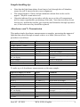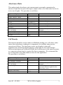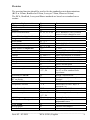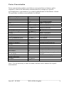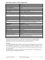
1
WPA S1200 Spectrawave
User Manual
English
Deutsch
Français
Español
Italiano
Biochrom Ltd
Certificate No. 890333
Declaration of Conformity
This is to certify that the
WPA Spectrawave S1200 and S1200T
Visible Spectrophotometer
Part number 80-3003-58 and 80-3003-59
Serial number 88000 onwards
manufactured by Biochrom Ltd. conform to the requirements of the following
Directives-:
73/23/EEC & 89/336/EEC
Standards to which conformity is declared
EN 61 010-1: 2001
Safety requirements for electrical equipment for measurement, control and
laboratory use.
EN 61326: 1998
Electrical equipment for measurement, control and laboratory use – EMC
requirements
Dated: 26th Oct 2004
Signed:
David Parr
Managing Director
Biochrom Ltd
Postal address
Telephone
Telefax
Biochrom Ltd
22 Cambridge Science Park
Milton Road
Cambridge CB4 0FJ
England
+44 1223 423723
+44 1223 420164
e mail: [email protected]
website: http://www.biochrom.co.uk
Registered in England No: 3526954
Registered Office: 22 Cambridge Science Park, Milton Road, Cambridge CB4 0FJ, England.
CONTENTS
Unpacking, Positioning and Installation
Essential Safety Notes
OPERATION
Introduction
Using the Instrument
Sample handling tips
Absorbance and % Transmission
Absorbance Ratio
Cell Density
Proteins
Scan
Factor Concentration
Standard Curve
Kinetics
To recall a saved method
1
1
2
2
3
4
4
5
5
6
7
8
9
11
12
SET UP
13
ACCESSORIES
14
ERROR MESSAGES
14
OUTPUT OF RESULTS
14
Use with serial printer
Use with chart recorder
USE WITH PC AND THE GRAFICO PC UTILITY
SOFTWARE
14
14
15
Installation
Introduction
Menu Descriptions
Practical Aspects
15
15
16
17
MAINTENANCE
18
After Sales Support
Lamp Replacement
Cleaning and general care of the instrument
Changing cell holder or removal for cleaning
Changing the brightness of the display
18
18
19
19
19
SPECIFICATION AND WARRANTY
20
Unpacking, Positioning and Installation
•
•
•
•
•
Inspect the instrument for any signs of damage caused in transit. If any damage is
discovered, inform your supplier immediately. Check the position of the metal lamp
bracket inside the lamp access area.
Ensure your proposed installation site conforms to the environmental conditions for safe
operation:
Indoor use only
Temperature 5°C to 35°C. Note that if you use the instrument in a room subject to
extremes of temperature change during the day, it may be necessary to recalibrate (by
switching off and then on again) once thermal equilibrium has been established (2-3
hours).
Maximum relative humidity of 80 % up to 31°C decreasing linearly to 50 % at 40°C
The instrument must be placed on a hard, flat bench or table that can take its weight (<2
kg) such that air is allowed to circulate freely around the instrument.
This equipment must be connected to the power supply with the power cord supplied. It
can be used on 90 - 240V supplies.
Switch on the instrument via the display after it has been plugged in. The instrument
performs a series of self-diagnostic checks for lamp performance, wavelength calibration
and diode array pixels; press F2 to proceed.
If the instrument has just been unpacked or has been stored in a cold environment, it should
be allowed to come to thermal equilibrium for 2-3 hours in the laboratory before switching on
to prevent calibration failure as a result of internal condensation.
•
•
The cell holder supplied with the instrument accepts standard 10mm pathlength glass or
plastic cells (adapters are available to convert it to accept 10, 12 and 16mm diameter test
tubes). It can be removed for cleaning if spillages occur by undoing the screws that hold
it or it can be flushed through with water in situ.
If the instrument has a heated cell holder option and it is on, allow 10 minutes for it to
come to thermal equilibrium. This cell holder cannot be removed.
If this equipment is used in a manner not specified or in environmental conditions not
appropriate for safe operation, the protection provided by the equipment may be impaired and
instrument warranty withdrawn.
Essential Safety Notes
There are a number of warning labels and symbols on your instrument. These are
there to inform you where potential danger exists or particular caution is required.
Before commencing installation, please take time to familiarise yourself with these
symbols and their meaning.
Caution (refer to accompanying documents).
Background colour yellow, symbol and outline black.
___________________________________________________________________
Issue 02 - 03/2005
WPA S1200, English
1
OPERATION
Introduction
Your spectrophotometer is a simple-to-use, microprocessor controlled instrument. It is a
diode array product (1024 pixels), has no moving parts and scans very quickly.
After switch on, calibration and pressing F2 to proceed the home page is shown offering the
choice of
• Repeat last operation
• Make a measurement
• Set up instrument
“Repeat last operation” returns the user to the last screen displayed when the instrument was
switched off, and provides a short cut to the last test that was performed.
Within “Make a measurement” your spectrophotometer has facilities for:
• measurement of absorbance, % transmission, ratio and concentration values
• cell culture optical density measurements at 600nm
• entry of a multi point standard curve in memory
• output of wavelength scan to display
• output of kinetics assay to display
• application of a factor to an absorbance change over a specified time interval for an
enzymatic determination (reaction rate)
• storage of up to 99 user defined methods
Within “Set up instrument” your spectrophotometer can be set up to
• select the display language option (English, French, German, Spanish, Italian)
• link via a serial lead to either a serial printer for hardcopy output or to a PC for
download of results to spreadsheet
• link via a converter lead to chart recorder
• set the date for print outs
The instrument is supplied with Grafico PC utility - on the accompanying CD - and a serial
lead. These provide the user with the means to capture, print and store data from the
instrument to a PC. Specifically it
•
produces a printable graphical plot of the scan, in Abs
•
logs date, time and serial number with any output from the instrument
•
produces a results log in order to store, tabulate and subsequently print output from
the instrument
•
enables export of the output from the instrument to Excel as a text file
A tutorial on UV/Visible spectrophotometry is included as part of the Grafico software.
___________________________________________________________________
Issue 02 - 03/2005
WPA S1200, English
2
Using the Instrument
The back-lit liquid crystal display is very easy to navigate around using the function /
select and arrow keys on the hard wearing, spill proof membrane keypad.
Keypad
F1, F2, F3, F4
3456
ESC
R
T
Display
◊
RT
The function select / entry soft keys on the keypad are situated next to
the corresponding option on the display, and are used to select an
appropriate mode
When a parameter within a mode needs selecting or changing (as
indicated by highlighted text on the display), the four arrow keys
(3456) are used in conjunction with the function keys to make that
selection or change. Use F4 to implement change, followed by 34 to
choose between options indicated, and 56 to enter alphanumeric
characters (for example in the selection of a wavelength or entry of a
method title). Then use F4 to accept the change made.
to escape or stop making measurements
to set reference to 0.000AU or 100%T on a reference solution at the
current wavelength in the mode selected, or to do a reference scan if in
scan mode
to start making measurements
The following symbols will appear in bottom right hand corner and mean
the following:
Use 3456 to select option
Ready to set reference or run sample
___________________________________________________________________
Issue 02 - 03/2005
WPA S1200, English
3
Sample handling tips
•
•
•
Note that the light beam shines from front to back through the cell chamber;
ensure the cell is inserted in the correct alignment.
The optical height is 15mm, and the minimum volume that can be used is
approx. 700µl in a semi-micro cell.
Align the indicator line on test tubes with the arrow on the cell compartment
area to ensure reproducible positioning of the tube. Note that test tubes do not
last forever, and that the surface gets scratches and blemishes through repetitive
use; if this is the case they should be replaced.
Absorbance and % Transmission
This makes simple absorbance measurements on samples, measuring the amount of
light that has passed through a sample relative to a blank (this can be air). The
procedure is as follows:
Option on display or action
Make a measurement
Single / Multi λ / Ratio
Single λ
Abs / % T
Set λ
Accept λ
Insert reference
RT on display
Insert sample
Repeat as necessary
To exit
Press
F2
F1
F1
F1
F2, then 56
F2
R
T
Comment
Alternates between the two
Select wavelength
Used for subsequent samples until
changed
Value is displayed
ESC
To make up to 4 absorbance measurements on the same sample:
Option on display or action
Make a measurement
Single / Multi λ / Ratio
Multi λ
Set λ’s
Select λ
Repeat as necessary
All OK
Insert reference
RT on display
Insert sample
Repeat as necessary
To exit
Press
F2
F1
F2
F1, then 56
F1, then 56
F4
R
T
Comment
Select first wavelength
Select second wavelength
Used for subsequent samples until
changed
Absorbance values are displayed
ESC
___________________________________________________________________
Issue 02 - 03/2005
WPA S1200, English
4
Absorbance Ratio
This makes simple absorbance ratio measurements on samples, measuring the
amount of light that has passed through a sample relative to a blank (this can be air)
at two wavelengths. The procedure is as follows:
Option on display or action
Make a measurement
Single / Multi λ / Ratio
Ratio
Remove this row
Set λ1
Accept λ
Set λ1
Accept λ
Insert reference
RT on display
Insert sample
Repeat as necessary
To exit
Press
F2
F1
F3
Comment
F2, then 56
F2
F2, then 56
F2
R
Select wavelength
T
Select wavelength
Used for subsequent samples until
changed
Ratio is displayed
ESC
Cell Density
This function should be used to make an OD600nm reading on a cell culture rather
than a direct absorbance reading as it compensates for turbidity using an autocorrection at 800nm. The absorbance at two wavelengths is measured
simultaneously and an algorithm applied to compensate for the scattered light.
Different instruments give different OD600 due to differences in the optical systems,
so a conversion factor may be required for direct comparison. We recommend the
use of disposable cells rather than test tubes for this application.
The procedure is as follows:
Option on display or action
Make a measurement
Cell Density / Proteins
Insert reference
RT on display
Insert sample
Repeat as necessary
To exit
Press
F2
F2
R
T
Comment
Used for subsequent samples until
changed
Value is displayed; an autocorrection factor is applied to the
Absorbance value.
ESC
___________________________________________________________________
Issue 02 - 03/2005
WPA S1200, English
5
Proteins
The proteins function should be used to for the standard protein determinations
(BCA at 562nm, Bradford at 595nm, Lowry at 750nm, Biuret at 546nm).
The BCA, Bradford, Lowry and Biuret methods are based on a standard curve
routine:
Option on display or action
Make a measurement
Cell Density / Proteins
Proteins
Select Protein method
Press
F2
F2
F2
F1, F2, F3 or F4
Enter Dilution if applicable
Program method
Select Units
Accept
Select Calibration option
Enter number of Replicates
Accept
Set Std
Change
....
Accept
Change
....
F2, then 5, F4
F1
F1, 56
F4, 6
F1, 34, F4
56
F4
F1
F1, then 56
F3
F4
F1, then 56
F3
Incorrect entry?
F3, then F1,
56, F4
Standards are all OK
Insert reference
RT on display
Insert Standard 1
If replicates selected
F4
R
Insert Standard 2
6T
Incorrect entry?
All OK
Change Curve Fit algorithm
F3, then F1,
56, F4
F4
F3, then 6, F4
View Graph
Accept graph
F4
F3
T
4T
Comment
BCA, Bradford, Lowry or Buiret
protocol can be changed to suit:
. . . . moves decimal point
Cal is highlighted
Select Std
1, 2 or 3
Goes to Calibration Curve page
1 is highlighted (maximum is 5)
Enter concentration of standard 1
Moves decimal point
2 is highlighted
Enter concentration of standard 2
Moves decimal point
Repeat as necessary
Clears entry prior to re-entry
Use F3 to clear standard from
experiment
Accept Concentrations
Used for subsequent samples until
changed
Absorbance for Std 1 is measured
Absorbance for Std 1 Rep 2 is
measured (A2)
Absorbance for Std 2 is measured
Repeat as necessary
Clears entry prior to re-entry
Accept Standards
Select linear least squares or
polynomial curve
Can now run samples
___________________________________________________________________
Issue 02 - 03/2005
WPA S1200, English
6
To run samples
All OK
Run
Insert reference
RT on display
Insert sample
Repeat as necessary
To exit
F1
F1
R
T
Used for subsequent samples until
changed
Concentration is displayed
Ensure Autoprint in set-up is set to off.
Scan
An absorption spectrum can be obtained from your instrument, enabling simple
identification of peak height and position. The procedure is as follows:
Option on display or action
Make a measurement
Scan
Abs / % T
Insert reference
RT on display
Insert sample
Repeat as necessary
To identify peaks:
Move cross hairs
To zoom in on a region of
interest:
Zoom
Zoom in
Zoom out
To exit
Press
F2
F4
F1
R
Comment
T
Alternates between the two
Used for subsequent samples until
changed
Scan is displayed
34
Abs and λ values appear at top
F2, then
3456
F1
F1
ESC
Move box that appears on display to area
of interest
Examine detail
Return to original data
___________________________________________________________________
Issue 02 - 03/2005
WPA S1200, English
7
Factor Concentration
Factor concentration mode is used when a conversion factor is known, and is
required to convert the absorbance measurement for a sample at a specific
wavelength into a concentration, by a simple multiplication of absorbance x factor.
The procedure to define a new method is as follows:
Option on display or action
Make a measurement
Select a method
New
Change Name
Accept
Change Wavelength
Accept
Select Units
Accept
Select Calibration option
Enter Factor
....
Positive or negative?
Accept
Kinetics
All OK
Run method
Insert reference
RT on display
Insert sample
Repeat as necessary
To delete
To exit
Press
F2
F3
56
F1
F4, then 56
4, then 56
4, then 56
F4
F4, then 56
F4
F4, then 56
F4
F4, then 34
F4 then56
F3
F2
F4
Comment
Select method number
Name is highlighted
Enter first character of name
Enter second character of name
Repeat as necessary
λ is highlighted
Units is highlighted
Cal is highlighted
Select Factor
Moves decimal point
Alternates between the two
Leave as no
F1
F1
R
T
Accept method protocol
Used for subsequent samples until
changed
Concentration is displayed
F3, then F1
ESC
Note: It is not necessary to enter the name, and this can be omitted for a quick
measurement.
___________________________________________________________________
Issue 02 - 03/2005
WPA S1200, English
8
Standard Curve
The construction of a multi-point calibration curve from standards of known
concentration in order to quantify unknown samples is a fundamental use of a
spectrophotometer; this instrument has the advantage of being able to store this curve
as a method, using up to 5 standards.
To include a zero concentration standard, include this in the number of standards to
be entered and enter 0.00 for concentration; use a blank when required to enter
standard
The procedure to define a new method is as follows:
Option on display or action
Make a measurement
Select a method
New
Change Name
Accept
Change Wavelength
Accept
Select Units
Accept
Select Calibration option
Accept
Set Std
Change
....
Accept
Change
....
Incorrect entry?
Standards are all OK
Insert reference
RT on display
Insert Standard 1
Press
F2
F3
56
F1
F4, then 56
4, then 56
4, then 56
F4
F4, then 56
F4
F4, then 56
F4, 6
F4, then 34
F4
F1
F1, then 56
F3
F4
F1, then 56
F3
F3, then F1,
56, F4
F4
R
T
Insert Standard 2
T
Incorrect entry?
F3, then F1,
Comment
Select method number
Name is highlighted
Enter first character of name
Enter second character of name
Repeat as necessary
λ is highlighted
Units is highlighted
Cal is highlighted
Select Std
Goes to Calibration Curve page
1 is highlighted (maximum is 5)
Enter concentration of standard 1
Moves decimal point
2 is highlighted
Enter concentration of standard 2
Moves decimal point
Repeat as necessary
Clears entry prior to re-entry
Accept Concentrations
Used for subsequent samples until
changed
Absorbance for Std 1 is measured
Std 2 is highlighted
Absorbance for Std 2 is measured
Std 3 is highlighted
Repeat as necessary
Clears entry prior to re-entry
___________________________________________________________________
Issue 02 - 03/2005
WPA S1200, English
9
All OK
Change Curve Fit algorithm
56, F4
F4
F3, then 6, F4
View Graph
Accept graph
F4
F3
To run samples
All OK
Run
Insert reference
RT on display
Insert sample
Repeat as necessary
To delete
To exit
To delete
To exit
F1
F1
R
T
Accept Standards
Select linear least squares or
polynomial curve
Can now run samples
Used for subsequent samples until
changed
Concentration is displayed
F3, then F1
ESC
F2, then F1
ESC
Ensure Autoprint in set-up is set to off.
___________________________________________________________________
Issue 02 - 03/2005
WPA S1200, English
10
Kinetics
Kinetics studies, where the change in absorbance needs to be followed as a function
of time at a fixed wavelength, can be readily performed.
Reagent test kits are routinely used for the enzymatic determination of compounds in
food, beverage and clinical laboratories by measuring NAD / NADH conversion at
340 nm. The change in absorbance over a specified time period can be used to
provide useful information when an appropriate factor, defined in the reagent kit
protocol, is applied. Reaction rate and enzyme activity can be calculated if the factor
used takes account of the absorbance difference per unit time, as opposed to the
absorbance difference per se.
For this reason, the change in absorbance per minute (∆A/min), concentration
(∆A/min x factor) and correlation coefficient (calculated from a best fit of the data
points) are displayed. They may not be relevant for simple kinetics experiments.
The procedure to define a new method is as follows:
Option on display or action
Make a measurement
Select a method
New
Change Name
Accept
Change Wavelength
Accept
Enter Units
Accept
Select Calibration option
Enter Factor
....
Positive or negative?
Accept
Kinetics
Accept
Enter Start Time
Accept
Enter time interval between
each measurement
Press
F2
F3
56
F1
F4, then 56
4, then 56
4, then 56
F4
F4, then 56
F4
F4, then 56
F4
F4, then 34
F4 then 56
F3
F2
F4
F4, then 34
F4
F4, then
3456
F4
F4, then
3456
Comment
Select method number
Name is highlighted
Enter first character of name
Enter second character of name
Repeat as necessary
Wavelength is highlighted
Units is highlighted
Cal is highlighted
Select Factor
If required; this is used to convert
∆A/min to Concentration
Moves decimal point
Alternates between the two
Select Yes or Fixed time *
Start is highlighted
Usually 00m 00s, unless there is a lag
time
Interval is highlighted
Minimum interval is 10 seconds
___________________________________________________________________
Issue 02 - 03/2005
WPA S1200, English
11
Accept
Enter end time
F4
F4, then
3456
Accept
Run method
Insert reference
RT on display
Insert sample
F4
F1
R
To view data
Use Page Up and Page Dn
To view graph
T
F2 or F3
F1
ESC
End is highlighted
Maximum time is 59m 59s after
completion of start time
Maximum number of readings is 20,
so maximum end time is 20 x the
time interval
Used for subsequent samples until
changed
Abs values displayed for each time
interval
At end of run, calculated ∆A/min,
correlation coefficient and
concentration are displayed
Return to values
Repeat as necessary
To exit
ESC
* The Fixed time option is for a single time measurement after a specified time, and
therefore no options for start time, time interval and graphics are available.
• If the instrument is connected to a chart recorder the output is linearly fitted
between data points as the software automatically interpolates these for the
benefit of presentation.
• If you have a factory fitted electrical heated cell holder version of the
instrument, go to Set-up to switch this facility on (37°C). Allow 10 minutes for
the instrument to come to thermal equilibrium.
To recall a saved method
Option on display or action
Make a measurement
Select a method
Accept
Run method
Insert reference
RT on display
Insert sample
Press
F2
F3
56
F4
F1
R
Comment
Select method number
Selected method is recalled
Used for subsequent samples until
changed
T
___________________________________________________________________
Issue 02 - 03/2005
WPA S1200, English
12
SET UP
Option on display or action
Set up instrument
Press
F3
Set Language
Select display language
F1
56
Accept
To exit
F1
ESC
Comms/Software Update
Select serial printer or PC
F2, F1
F1
Set Baud of 9600 or 38400
F2
Auto-print
F3
Accept
To exit
F4
ESC
Set Date / Time
Select format
Enter values
Accept
To exit
F3
F1
3456
F4
ESC
Heater control*
Heated cell
F4
34
Accept
To exit
F4
ESC
Comment
English, French, German,
Spanish, Italian
Select Communications
Alternates between them, with default
settings for each option:
Printer 1 is S1000P
Printer 2 is Martell / Seiko DPU-414
PC is for download to spreadsheet
software and Grafico
Use 9600 for Grafico and 38400 for
download to spreadsheet software
Use only if printer connected; select on
for automatic increment of sample
number and print out after measurement.
Not recommended for standard curve.
Do not use in PC mode as output is
automatic anyway
European or North American
Enter as appropriate
May not be available*
Select on for thermostatting at
37°C
*Heated cell holder factory fitted version only. This option cannot be fitted
retrospectively to an instrument.
___________________________________________________________________
Issue 02 - 03/2005
WPA S1200, English
13
ACCESSORIES
PC serial cable (spare)
S1000P serial printer (includes serial printer cable)
Seiko DPU-414 printer
Serial cable for Seiko printer
Chart recorder interface cable
Test tube adapters (10, 12, 16mm)
80-3001-00
80-3002-53
80-2108-80
80-2118-18
80-3003-55
80-2117-47
ERROR MESSAGES
After switch on, the instrument undergoes self-diagnostic tests for the tungsten lamp,
wavelength calibration and diode array as part of its calibration procedure (9 for
OK, X for fail). The results of this test are displayed and can be printed out or
output to PC for filing and GLP (Good Laboratory Practice) purpose. The messages
for tungsten lamp and / wavelength calibration are self explanatory, involving
checking that the cell compartment is clear or replacement of the tungsten lamp. In
the unlikely event of a diode array fail message contact your local supplier.
OUTPUT OF RESULTS
Use with serial printer
Note that all results can be output to PC using the serial lead and Grafico software
supplied on the user manuals CD.
Seiko DPU-414 settings:
Dip SW-1
Serial, Auto line feed off
Dip SW-2
40 column width, International character set, USA
Dip SW-3
Baud rate 9600 bps
Note that the 80-2108-18 lead that is required will need two small nuts removing
before connection.
Use with chart recorder
Kinetics results can be output to a chart recorder using the appropriate cable (803003-55). Voltage setting is 1V per 1 Absorbance unit (± 10 %) with an offset of
1V = 0.000 Abs on the chart recorder; corresponding %T values are 1V per 100%T
(± 10 %) with 0V = 0%T.
To make the chart cable yourself, you require a female 9 way D type at one end with
two (1 red, 1 black) 4mm banana plugs at the other (depending on the chart recorder)
and 2 metres of coaxial cable or screened twin core, with the shield connecting the
black plug and pin 5 and the core connecting the red plug and pin 1.
___________________________________________________________________
Issue 02 - 03/2005
WPA S1200, English
14
USE WITH PC AND THE GRAFICO PC UTILITY
SOFTWARE
Your instrument is supplied with a serial lead and Grafico software (on the user
manuals CD) that enables it to be connected to a PC so that results can be captured,
stored, printed and transferred into other applications easily. In particular, a
complete wavelength scan can be visualised on the PC and copied/pasted into a word
document or powerpoint presentation. An informative tutorial on aspects of
UV/Visible Spectrophotometry is available as part of the software.
Installation
Prior to installation of Grafico, you should have the following options selected in your
spectrophotometer instrument set up:
PC / 9600 Baud / Autoprint off
The software takes up approximately 0.5Mb of hard disk space when installed. Proceed as
follows to install the software:
1.
Place CD into the CD drive of the PC
2.
Use Windows explorer to locate the setup.exe file Grafico folder within the
appropriately named instrument folder on the user manuals CD
3.
Double click on this so that the software installs, filling out the information as
requested.
4.
The software can be started directly by Start > Programs > Grafico.
Introduction
•
•
•
•
When Grafico is selected, you are prompted to enter the file details (note that
the title entered here is used as the title of the wavelength scan graph). After
pressing OK, the instrument (it should be already switched on and connected to
the PC with the serial lead) is recognised by the software.
There are two parts to the Grafico software, data-logging and scan.
The default mode is data-logging; this receives instrument output from
absorbance, %T, concentration and rate measurements (including time and date
stamp).
o Results can be copied from Grafico and pasted directly into Excel
for ease of data transfer. Alternatively results can be saved and
opened up using Excel.
If scan mode is selected (View > Scan mode), the full 330-800nm wavelength
scan output from the instrument is shown (just press the run key as usual).
Multiple peaks can be identified using a trace routine and labelled if required
(by dragging the icon at the left side of the displayed graph and releasing at the
appropriate point).
o Graphs can be copied and pasted into Word, Excel or powerpoint
o Graphs can be saved in a format that can be opened directly by
Excel
___________________________________________________________________
Issue 02 - 03/2005
WPA S1200, English
15
Menu Descriptions
File
New
Save / Save As
Setup
Print
Print Setup
Exit
Edit
Copy
Clear
Select All
View
Scan mode
Clears any existing data and starts a new report. Prompts for file
details (user name, organisation, title, descriptive text)
Saves the data file in the file format selected. The file details are
included with this data
Displays a tabbed dialogue box so that automatic post process
options for saving of graph, printing of graph and the graph scaling
parameters can be defined. The default data directory can be
defined and is used for all save operations.
Prints the entire file, including a header if defined in File>New
Runs the Common Print Dialog function to set up the printer
Closes the application
Copies the data to clipboard for pasting into another application; in
data-logging and scan modes this is text and graphic, respectively
Clears the data from the data set
Selects data and header together
Set scale
Display grid
Toolbar
Status bar
Switches between scan and data logging modes. Successive scans
overwrite existing scans on the display and can be saved if the
autosave function is on
Shows the file details entered at the start (or after File > New) and
allows modification of these details, if required
Automatically sets the scale of the absorbance axis to optimise
presentation (2.5, 2.0, 1.5, 1.0, 0.5, 0.2 or 0.1A)
Sets the scale to user preference (Full, Auto, Define)
Toggles on/off the grid on the graph (for presentation purposes)
View menu bar as icons
View status bar at bottom of display
Help
Tutorial
Help topics
About
View tutorial on UV/Visible spectrophotometry
View help topics
View version number etc
File details
Autoscale
___________________________________________________________________
Issue 02 - 03/2005
WPA S1200, English
16
Practical Aspects
Data logging mode
• When exporting rate mode results you can add the time in 10 second intervals to
the spreadsheet manually (note that first data point is after 10 seconds, not zero
seconds) and then graph the absorbance / time data (see scan mode – export to
excel for more details).
Scan mode
• Files can be saved as *.txt, *.csv (opens directly in Excel when double clicked)
or *.wmf (picture) formats
• Label a peak by dragging and releasing the icon at the left side of the graph.
The absorbance/wavelength details are shown in the title bar. Dragging it again
moves the label; moving it the left hand side takes the label away. Multiple
peaks can be added.
• Use display grid off for clearer presentation.
• Data can be output in absorbance only
Scan mode – export to Excel and graphing
• If saving as a *.txt file, save the results to folder of choice.
o Use Excel to open this file; with files of type set to “all files”
o Note that saving as a *.csv file and double clicking on it will open
Excel directly
• Highlight the wavelength and absorbance values and click the graph icon
• Select chart type “XY Scatter” and the curved lines (no data points) option
• Label the axes etc as required
• Double click on the x-axis, select Scale and minimum to 330 and maximum to
800
• Set colour scheme to suit your preferences
___________________________________________________________________
Issue 02 - 03/2005
WPA S1200, English
17
MAINTENANCE
After Sales Support
Support agreements that help you to fulfil the demands of regulatory guidelines
concerning GLP/GMP are available.
• Calibration, certification using filters traceable to international standards
• Certificated engineers and calibrated test equipment
• Approved to ISO 9001 standard
Choice of agreement apart from break down coverage can include
• Preventative maintenance
• Certification
When using calibration standard filters, insert such that the flat surface is facing
away from the spring end of the cell holder
Observe all necessary precautions if dealing with hazardous samples or solvents.
Lamp Replacement
A replacement lamp is available from your supplier using the following part
numbers:
Tungsten Lamp, S1000L
80-2115-33
(use only this tungsten lamp as it is supplied with the connection wires; others will
not operate correctly in this spectrophotometer)
•
•
•
•
The design of the lamp area is such that users are able to change their own
lamps. No lamp alignment is necessary as the lamp is pre-aligned.
The lamp becomes hot in use. Ensure it is cool before changing it.
Do not touch the optical surfaces of the lamp with your fingers (use tissue); if
touched, the area should be cleaned with iso-propanol.
Instructions for lamp change are provided with the lamp and overleaf.
___________________________________________________________________
Issue 02 - 03/2005
WPA S1200, English
18
To change the lamp, proceed as follows:
1.
2.
3.
4.
5.
6.
Switch off the instrument, remove the sample from the cell holder and
disconnect the power supply cord
Remove the protective layers at the lamp access and plug in points on the
underneath of the instrument
Remove the lamp wires from the groove by gently unclipping it
Remove the lamp by twisting the lamp assembly anti-clockwise
Remove the lamp connection end by gently pulling with your fingers
Replace with new lamp using the reverse of these actions
Cleaning and general care of the instrument
External cleaning
Switch off the instrument and disconnect the power cord.
Use a soft damp cloth.
Clean all external surfaces.
A mild liquid detergent may be used to remove stubborn marks.
Changing cell holder or removal for cleaning
• Undo the screws that are visible on the top of the cell holder using a small flat
headed screwdriver and lift the holder out by holding onto the projection; this may
require pushing to the right as you do so in order to prevent fouling against the left
side of the instrument cover. If necessary, the cell holder can be helped out by
pushing from the bottom of the instrument.
• Insert the test tube holder and secure in place using the same screws.
• Note that as well removal for cleaning, spillages in the cell holder can be flushed
through using water from a squeeze bottle in order to prevent crystallisation /
fermentation of residues.
Changing the brightness of the display
To change display brightness, proceed as follows:
1.
2.
3.
Ensure the instrument is on and that there is no sample in the cell holder
Remove the protective layer at the lamp plug in point (underneath and at the rear
of instrument)
Place the instrument on its back, insert a small flat headed screwdriver into the
potentiometer slot and turn it right or left until a suitable level of brightness is
obtained.
___________________________________________________________________
Issue 02 - 03/2005
WPA S1200, English
19
SPECIFICATION AND WARRANTY
Wavelength range
Monochromator
Wavelength calibration
Spectral bandwidth
Wavelength accuracy
Wavelength reproducibility
Light sources
Detector
Photometric range
Photometric linearity
Photometric reproducibility
Stray Light
Stability
Noise
Analogue output
Digital output
Dimensions
Weight
Power input
Safety standard
EMC emissions
EMC immunity
Mains harmonics
Susceptibility standard
Quality System
330 - 800 nm
Flat grating
Automatic upon switch on
7 nm
± 2nm
± 1nm
Pulsed Tungsten halogen
Diode array
- 0.300 to 2.500A, 0.3 to 199%T
± 2.0 % or ± 0.010A to 1.000A at 546nm, whichever is
the greater
< 0.002 A at 0A and 500nm
< 1%T 340nm according to ANSI/ASTM E387-72
± 0.005A/h at 0A and 546nm after warm-up
± 0.002A near 0A and ± 0.020A near 2A at 600nm
1V per 1 Abs (±10%), 1V = 0A offset
1V per 100%T (±10%), 0V = 0%T offset
9 pin serial
180 x 270 x 390 mm
1.75 kg
90-265 V, 50/60 Hz, 15 VA
EN61010-1
EN 61326-2.3 Generic emissions
EN 61000-4-6 Generic immunity part 1
EN 61000-3-2
IEC 801
Designed and manufactured in accordance with an ISO
9001 approved quality system
Specifications are measured after the instrument has warmed up at a constant ambient
temperature and are typical of a production unit. As part of our policy of continuous
development, we reserve the right to alter specifications without notice.
Warranty
Your supplier guarantees that the product supplied has been thoroughly tested to ensure that it
meets its published specification. The warranty included in the conditions of supply is valid
for 12 months only if the product has been used according to the instructions supplied. They
can accept no liability for loss or damage, however caused, arising from the faulty or incorrect
use of this product.
This product has been designed and manufactured by Biochrom Ltd, 22 Cambridge Science
Park, Milton Road, Cambridge CB4 0FJ, UK.
___________________________________________________________________
Issue 02 - 03/2005
WPA S1200, English
20