1
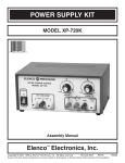
Summer 2009 Final Report:
Biped Head: First Iteration
Advisor: Dean Keith Buffinton, PhD
Report By: William Rittase
May 25 to August 7, 2009
Table of Contents
Summer Overview and Objectives………………………………………......3
Initial Specifications…………………………………………………………3
Design Overview…………………………………………………………….4
Observations from Construction and Testing………………………………10
Head User Manual………………………………………………………….13
Power Supply…………………………………………………………………….13
Joystick and Motor Control……………………………………………………...14
Camera System……………………………………………………...…………...16
Summary……………………………………………………………...……16
Bill of Materials……………………………………………………………17
Things to Work on in the Next Bipedal Head Design……………………..18
Things I’ve learned/helpful hints……………………………………..……18
Appendix…………………………………………………………………..20
Includes Information on Binocular Camera - Bumblebee2
2
Summer Overview and Objectives:
The Institute for Human and Machine Cognition (IHMC) is in the process of building a
bipedal walker which does not need a pre-programmed sense of its environment, but
rather adapts to his surroundings. Before this summer, the biped only had a two legs and
a torso. Our end goal was to build a head for the robot which would effectively serve the
following purposes.
1. Allow for an operator to see clearly and comfortably through the eyes of the
robot, especially while moving.
2. Allow the biped itself to gather an accurate representation of its surroundings so it
can manipulate itself around an area without running into objects or problem
areas.
3. While serving a functional purpose, the head should also be human-like and be
accepted as somewhat friendly by the general population.
Upon first glance, one can easily see that these are not objectively defined goals. Since
this is the first time something like this has been done, the main goals for this summer
would not accomplish creating a final product, but rather more clearly define what we
actually need. Therefore, we decided to start simple.
1.
2.
3.
4.
5.
6.
Research past humanoids and see what they use.
Design a concept of our own.
Build our concept.
Test it.
Improve on it.
Clearly define a concept of what we actually need and look out for areas of
improvement.
Initial Specifications:
The first iteration of the biped head must meet the following design considerations:
•
•
•
•
•
At least 2 DOF – pan and tilt
180º pan, 120º tilt – approximately 100 deg/s
Weighs less than 10 pounds
30 fps feedback video (minimum)
8” x 8” x 12” maximum
Other than these values, there were some other subjective problems that we were not sure
how to quantitatively define. For example, the cost of the head and the power
consumption should be as low as possible while maximizing the other specifications, but
we were not sure what exactly these numbers should be. A better idea of these concepts
should be determined by actually building and testing a head.
3
Design Overview:
The first design, after researching previous humanoids and looking at other papers, was
modeled after the legless BERTI robot (seen in Figure 1). From the initial pictures, the
robot appeared to have a “neck” joint. Basically, the cameras and any other sensors
would be placed above a 2 DOF neck like so.
Figure 1: Close-up of the BERTI Robot Neck
4
Figure 2: Schematic of 2 DOF “Neck” Joint
After much discussion, the “neck” joint was designed in ProEngineer and the first design
looked as such.
Figure 3: 2 DOF “Neck” Joint Initial Drawing
5
The motors were not sized in Figure 3, but the 3D model was used to make some basic
calculations for motor sizing. What we found was that the power of the motors would be
very high. The motors themselves would then be rather bulky and heavy, so we decided
to try a different approach. However, it is possible that this type of design could work. It
has its advantages and disadvantages. In its favor is the ability to simply have a neck
joint to operate off of. The joints are relatively simple and the operator could easily look
at the feet. However, the inertial moment produced by not lining up the axes of the
motors with the inertial centers of the system does introduce the need for stronger motors
and more power. Therefore, we decided to tone down the power requirements and
implement a system which aligned the inertial centers of the system with the motor axes,
seen in Figure 4. (NOTE: A neck joint is still a viable option. It makes the robot appear
more human-like and allows for easier separation of systems – neck and head.)
Figure 4: Schematic Diagram of Lining up the Motor Axes with Inertial Centers
(courtesy of Henry Sirot)
6
Figure 5: Initial 3D Head Lining up the Motor Axes with Inertial Centers
This design implemented a few new features. In addition to lining up the motor axes, we
also introduced the RC servo motor for the tilt. The RC servos are very strong and are
given commands to go to a certain position by pulse width modulation. The pan motor
still remained a DC motor, but we introduced an encoder to close the loop on its position.
Because the design team at IHMC was already using a similar setup with DC motors and
encoders, we decided it might be a better idea to try using some RC servos to determine if
that might be the way we want the head to go. In our next two designs, the tilt setup
remained about the same; however the pan changed a few times. We attempted to place
the servo at the base (Figure 6), but found there would be problems at the 90º servo
angles. The last iteration of the mechanics in the design can be seen in Figure 7, and the
design with the enclosure on it can be seen in Figure 8.
7
Figure 6: Pan Servo Setup (diagram courtesy of Henry Sirot)
One can see where the problems would be when the servo is ordered to 90º. Any amount
of torque would not be able to move the system since there is a pin joint in the servo
rudder connections.
Figure 7: 3D View of Final Design
8
Figure 8: Final Design with Partial Enclosure
In this design the motors were selected to provide enough torque to move the head at the
rate we wanted. We used a simple trapezoidal model to simulate the motion of the head
with a curve somewhat like the following (see Appendices for more information):
Velocity
200
180
160
Velocity (deg/s)
140
120
100
80
60
40
20
0
0
0.1
0.2
0.3
0.4
0.5
0.6
0.7
0.8
0.9
1
Tim e (s)
Figure 9: Plot of Head Motion for Motor Sizing
By using plots such as these and determining the rotational inertia we were attempting to
move, we could effectively size our motors. We eventually picked Futaba RC servos,
model S3107 for the pan and S3111 for the tilt.
9
Observations from Construction and Testing:
The metal parts for the head were machined over the next few weeks, making minor
adjustments were necessary. Slots were added to the camera mount so one could the
position the cameras to change the rotational center of inertia. This helped to manually
balance the system.
The next step was to add some sort of way to control the motion of the head. Joystick
control was desirable in the final stages of the head design, so it would be best to attempt
it in this desing phase to see figure out the problem areas. The basic setup involved an
SV203B servo control board which took readings from the potentiometers on the joystick
which was rewired to the board. A program was written in QBASIC to interpret these
signals and appropriately move the motors to their correct position with respect to the
joystick. A more detailed description can be found in the User Manual towards the end
of this report.
Several problems were found in the initial design.
Unfortunately, the weight and additional roational inertia of the head enclosure was not
taken into consideration in the motor sizing calculations. The end result was an effective
head without the enclosure, but a weak head when it was all put together. The pan had
intense backlash and the tilt was too weak. Therefore, a new motor for the pan was
bought for the pan (HiTEC HS-85MG) which had metal gears to decrease the backlash
we were seeing. In addition, it was about three times stronger. The stronger Futaba
S3107 servo was then moved to be the new tilt motor. The end result was better, but not
perfect. The pan motion was significantly improved – it had smoother motion with less
backlash and a faster response time with the attached enclosure. The tilt motion,
however, was not so great. At this point in the design, there is no real use to buy another
motor and machine the L-bracket again. What is to be learned from this is the fact that
the enclosure should be taken into consideration during the next design phase so that the
motors are sized correctly. If testing is to be done with the damping pads with the current
setup, the enclosure should be removed.
During testing, it was very difficult to alter any part of the design because so many parts
needed to be removed. In order to install the center enclosure piece for example, one has
to disconnect the rudder from the tilt motor, remove the L-bracket, take off the cameras,
screw the enclosure to the camera mount (which is difficult in and of itself), re-install the
cameras, replace the L-bracket, and reattach the motor. In addition, all the electronics of
the head need to be moved around frequently to make adjustments. The next design
should allow for easier access to parts for adjustment and less complexity in the wiring
setup.
Although the RC servos work very well, they have a very awkward mounting system on
the head. In addition, it was rather difficult to line up the axes of the internal axle and the
RC servo for the pan. The dimensioning of the machined parts becomes extremely
important. For example, one can see the internal axle design in Figure 10.
10
Figure 10: Internal Axle Design (courtesy of Henry Sirot)
The ball bearings are press fitted into the internal axle as well as the external axle (see in
the schematic on the right). In addition, there is a piece holding the body of the servo in
place that is not pictured here and needs to be aligned perfectly with this part. Even if the
machining is done perfectly, it is still difficult to assemble. Altogether, although the
design does work in practice, there should be an easier way to contruct this axle. All the
parts work together too closely and there is little room for error. If it breaks, there is no
real way to isolate the problem area. Ease of construction and maintenance should be
taken into consideration in the next design. This may mean removing the servos due to
their bulky and inconvenient gear boxes.
The wiring and circuit board placement restricted some motion of the head, especially
when the firewire cables were attached to the cameras. There is also simply not enough
room to fit all the wiring and circuit boards. Leaving room for electronics should be
implemented on the next design. The head, as it stands now, is simply too small. The
robot is around six feet tall without the head, and the first head prototype is only around
six inches high. There should be an increase in the size of the head not only because it
would look awkward on the biped, but to allow some more room for circuitry. The next
design should also include extra screwholes for cable clamps and mounting holes for
circuit boards.
Many simulations were created to replicate the effects of a damping system. There were
several extremely low frequencies which needed to be dampened, but this could be done
by simple camera movements collaborating with the gyroscope in the biped. There are
also some other shaky movements throughout, but this can be taken care of through a
simple image stabalization software package. The next step would be to see if some
passive stabalization system could be implemented in the design to rid the image from the
higher frequency vibrations. Although an appropriate damping coefficient was calculated
through simulation in Working Model, it is impossible to actually get this coefficient
11
from any manufacturer of damping materials. Therefore, several damping pads from
McMaster-Carr were purchased. To test the effectiveness of these pads on damping the
smaller vibrations, the camera system will be mounted on a helmet and a person will
walk around, using different damping pads. The images can then be processed and the
effects can be analyzed to determine their worth. Other ways of creating and testing a
passive stabalization system can and should be tried, but it should not be a top priority at
the moment.
Lastly, the entire vision system was largely ignored this summer. At first, a few
individual cameras with multiple lenses were bought to see how they work. Subjectively,
they work very well for what they are intended to do. However, we were unsure how to
continue with no feedback from the project leaders at IHMC. It now appears as though
IHMC wants to incorporate a 3D vision system to aid the operator. This means that the
vision system would need to be switched from a 1 or 2 camera system where the cameras
operate independently to a binocular system to produce 3D images. This will need to be
explored in more depth when the time comes. In addition to operator vision, we also
need to produce some robotic awareness as well. The Bumblebee2 binocular camera has
been tested to determine its resolution and accuracy, which turns out to be very good (see
appendix). However, there are other options to producing the machine vision, such as a
SICK laser scanner (one option that should definitely be explored). The next step is to
compile some sort of chart to directly compare the Bumblebee2 to a SICK laser scanner
and any other machine vision systems. This analysis can be done in parallel to any
construction of the head, but it is suggested that everything to do with the vision portion
of the project becomes a priority in the next design phase as it was mainly overlooked
this summer.
Specification Analysis
•
•
•
•
•
At least 2 DOF – pan and tilt
o Met
180º pan, 120º tilt – approximately 100 deg/s
o Only 90 º in the tilt and 120 º in the pan direction, but this can be changed
by altering the joystick setup and changing the gains
Weighs less than 10 pounds
o ~2.5 lbs with 2 cameras and lenses
30 fps feedback video (minimum)
o Up to 60 fps
8” x 8” x 12” maximum
o LxWxH = 7x7.5x8” with enclosure
In addition, the RC servos cost significantly less than DC motors with gearheads and an
encoder. The actual mechanical system cost around $250 plus the cost of machining.
The cameras and lenses cost an additional $1100. Therefore, this design was very cost
efficient. As far as energy is concerned, the mechanical apparatus operates at around
4W, but the cameras take some power to operate as well.
12
Head User Manual:
Power Supply:
The power supply should be around 7-12 V and should be able to provide around 500 mA
DC. This power should go to the white input on the security/limit switch board. The
black tongs go to power the actual head. This power runs directly to the motor controller
which in turn powers the motors and the joystick. The security board works as such:
Case 1: Circuit ready but
power to head not on
Case 2: Circuit read and
power to head on
Case 3: Circuit in default
Figure 11: Security Board LED Configurations
Obviously, if both the LED’s are off, the power to the board itself is not on. For Case 1,
if you want to set the servos at their neutral position, simply press the red button. That
will set the servos but not give them power. Pressing the white button will turn off the
red button and allow communication between the joystick and the head, hence Case 2.
Case 3 only occurs when the limit switch is pressed down. Immediately afterward, the
green LED should come back on and go back to Case 1. The circuit diagram is located
below.
13
Power to
Head
Figure 12: Limit Switch Circuit Diagram
Limit
Switches
Input
Power
Figure 13: Labeled Picture of Circuit Board
By examining the servo controller board, one can see that there is a voltage regulator
between the input power and the power to the servos. This regulator steps the voltage
down to the servos to around 5 V. This is necessary because the servos operate best
between 4.8 and 6 V and higher voltages can damage them.
Joystick and Motor Control:
The concept behind the joystick control for the motors is relatively simple. There are two
wires for potentiometers in the joystick (one for right to left, one for front to back) and
two wires for the power to the joystick (power and ground). The power comes directly
from the motor controller to the joystick, which then sends signal voltages back to the
controller. This in turn commands the servos to a position based on the voltage. The
code was written to the board in simple QBASIC. The code can be seen below.
14
Figure 14: QBASIC Code on Servo Controller
The program is relatively simple. It selects an input from the joystick, converts the
analog voltage to a digital signal for the servo, then sends the signal. It does this for both
the joystick potentiometers and both the servos and then repeats.
If you want to write another program to run the joystick-head setup, take the following
steps to write it to the board after it has been connected to the computer.
1. Open the command prompt in Windows (Start Æ All Programs Æ Accessories Æ
Command Prompt)
2. Go to the correct directory where svbas.exe is stored (cd <pathname>)
3. Type ‘edit <filename>.sv’
4. Write the program
5. Save and close
6. Run svbas.exe by typing svbas <filename> /<port number>
7. Type ‘svbas /r’ to run the program
8. Type ‘svbas /auto’ to put it on the board
15
After doing step 8, the program should run automatically from the board without being
connected to the computer.
Camera System:
1. Install the PCI card into a computer tower.
2. Install the software package (either Flycap.exe for Firefly or triclopsDemo.exe for
the Bumblebee2). Read the manual located in the corresponding camera box for a
more detailed installation procedure.
3. Plug in the Firewire cable to the back of the camera and attach it to the PCI card.
4. Open the correct software and accept the default values.
5. If there is a problem with the image, try the following:
a. Check to see if the lens cap is still on
b. Adjust the focus/lighting by turning the different parts of the lens
c. Make sure the right mount is on the camera. There is a C-mount adaptor
which comes with the camera. If a CS-mount lens is being used on a Cmount (which will screw in) the image will be impossible to focus.
6. Once you see a window pop up on the screen, you can adjust the lens properties
by turning the knobs on them. In addition, you can change other settings in the
Properties menu. Fine tune them to fit your needs.
Summary:
Overall, this summer’s project was a success, succeeding in some areas while falling a
little short in others. The design itself works very well without the added weight of the
enclosure, which was not taken into consideration in the motor calcs. With the enclosure,
the pan motion works well, but the tilt is still too weak. The joystick moves the head
smoothly and provides very good video quality. However, the wires frequently get in the
way of the motion and need to be accounted for in the second design.
The next step in this project is to work on defining what kind of vision system to use and
how it’s going to interface it with the biped. The machine and operator vision should be
top priorities in the upcoming designs, as that is what the head is ultimately intended to
do. The appropriate cameras should be selected and adequately tested. The electronics
(limit switches, control boards, any kind of wiring, etc.) should be taken into
consideration in the design of the mechanics. The RC servos worked well but should
probably be changed in the next design. They have amazing power for their size
however, and the idea should not be completely thrown out. Nonetheless, a DC
precision-geared motor with an encoder to close the loop may be better and have less
play/backlash.
16
*Bill of Materials:
Pan joint:
Feature
6383K16 Ball bearing
Hitec HS-85MG servo motor
Number
2
1
Tilt joint:
Feature
57155K377 Ball bearing
Futaba S3107 servo motor
Dubro Swivel ball links
Number
2
1
4
Global head:
Feature
2-56 flat head screws 3/8”
10-32 flat head screws 5/8” and nuts (PDL)
Pontech SV203-B
Firefly MV camera
Varifocal lens
Wide angle lens
Extension wire for servo
Number
1 box
1 box
1
2
1
1
1
Security Board:
Feature
Push button
LED
Small 8 pins connectors
Limit switch
12V Relay
Small 2 pins connectors male
Small 2 pins connectors female
520Ω resistors
7805CT 5V regulator
Number
2 (one white, one red)
2 (one green, one red)
1
4
1
2
2
2
1
*Courtesy of Henry Sirot
17
Things to Work on in the Next Bipedal Head Design:
1.
2.
3.
4.
5.
6.
Coordinate placement of electronics/circuit boards/wires in design.
Make the head bigger (the biped is almost 6 feet without the head...)
Consider the effects of having an enclosure on the motor calculations.
Implement and test a damping system.
Wireless control?
Define the vision requirements more adequately. If we are to continue with 3D
vision, we could perhaps use the Bumblebee2 as the next set of cameras.
7. Work on the head-body interface.
Things I’ve learned/helpful hints:
1. If you’re a MechE and trying to work on robotics, be prepared to learn electrical
engineering, computer science, all kinds of programming, and lots of machining.
It would have been very helpful if I had taken a course on machining before this
summer/if I had paid attention in my intro to electronics class, Elec105. If you
are in any of those fields other than MechE, be prepared to learn pretty much
everything on the job.
2. Ask lots of questions. People who are specialists in electronics/programming/
machining know more than you probably do about their subject. However, if you
feel that something they are saying might be wrong or you might have a better
idea, SPEAK UP! Either you do not understand it correctly and should learn
more, or maybe you’re correct in the first place.
3. If you get frustrated, work through it and you’ll learn something.
4. Write down everything in your lab notebook. Don’t include the smallest details,
but if you’re making an adjustment to a feature, make sure to document it.
There’s nothing worse than doing it all over again and wasting lots of time. My
lab book and Henry Sirot’s lab book can be found in the robotics lab.
5. When doing objective testing/data collection, make sure the tests can be replicated
and take lots of pictures of the setup. When doing subjective data collection,
make sure you document it somehow (video, pictures, noise plots, etc.) in order to
defend your results.
6. Try to think from the perspective of the user/operator. The head is possibly the
most operator-controlled part on the body. The user will be moving the head
around and seeing through the biped’s eyes most of the time. Make sure that he
will be comfortable and see what he needs to see.
7. Try and coordinate everything – wires, motors, circuit boards, gearing, anything.
It requires lots of work to do this after machining has already taken place. Extra
screw holes for cable clamps may help.
8. Aligning a center of mass about the axis of rotation is very important when using
motors. If you need to, increase the factor of safety on the motor torque or make
parts that have a liberal amount of flexibility in their positioning so you can adjust
it after construction.
18
9. Make sure to check shipping times on all items. If it’s going to take 8 weeks to
get a part, it’s normally not worth it. Try and find something else that’s similar
and will do the same job.
10. It should not be difficult to adjust parts on the head (take them off, interchange,
etc.). The next design should allow for easier access to parts for adjustment and
less complexity in the wiring setup so that modifications can be made easily.
11. Make sure the parts are dimensioned correctly. Double check your dimensions
before you get parts machined. Having to make parts several times wastes your
time. Also leave room for some error in your dimensions. If every tolerance
needs to be to +/- 0.001 inches, you’re most likely doing something either wrong
or unnecessary. If you have any questions about dimensioning/tolerances, talk to
someone who has experience (i.e. Dan Johnson).
19
Appendices:
Assessment of Bumblebee2 Binocular Vision System
By: William Rittase with testing assistance from Henry Sirot
June 24, 2009
Introduction
The Bumblebee2 is a binocular system which has the ability to create a 3-D point cloud
of all pixels in its view using its stereoscopic vision. By defining several key parameters,
one can adjust the range, resolution, accuracy, and speed of the device. This assessment
will discuss the camera’s capabilities which have been discovered after messing around
with device as well as suggest some possible applications for it in our bipedal robot.
Setup
The initial setup was very simple. All one has to do is place an included IEEE-1394 PCI
card into an open PCI slot, install the software, and plug in the camera to transmit
images. In addition, the Bumblebee2 package comes with a general purpose I/O 12-pin
connector which can also be used to transmit data instead. The latter method has not
been attempted, but might be useful for the biped.
Capabilities
According to Point Grey’s website, the Bumblebee2 can have the following lens focal
lengths which give it the corresponding horizontal field of view (HFOV): 2.5mm (100°
HFOV), 3.8mm (65° HFOV), 6mm (43° HFOV). The camera which was evaluated has
6mm focal length lenses. Although there was less distortion in the image due to the
larger focal length, it might be necessary to get a larger HFOV depending on the
camera’s application.
Many different parameters can be adjusted to give the optimum image depending on the
surroundings. By messing around with the software, the main parameters to change are:
stereo mask, max disparity, minimum disparity, the rectification qualities, and the
validations. The stereo mask allows the user to change how coarse the image is and
really does not affect the fps. The maximum and minimum disparities allow the user to
select the range of distances the camera measures without changing the fps either. The
rectification qualities are most likely going to be very important. Increasing the quality
of the rectification drastically decreases the fps, but limits distortion. Lastly, the
validations are important to consider because they help establish correspondence between
images. I suggest turning on surface, texture, and back-forth for office-like environment.
20
Figure 1: Example Standard Settings of Stereo Parameters
One aspect of the Bumblebee2 that has not been looked into is its programming abilities.
It comes with a library of sample programs as well. In addition, it comes with a library
of commands for C++ that can be used to change any of the parameters of the device at
any time. This could be very useful for the biped. One could change the disparity range
for looking at close distances toward the feet for mapping the ground or long distances to
map an environment for easy navigation. Basically all the parameters mentioned
previously are adjustable.
Testing
We used many ranges of disparities to evaluate the surroundings, but set the other
parameters and left them (if anyone wants to know the standard settings we used, email
me). By placing several small objects – stapler, eraser, weight, soda can - from a height
of about 1 meter (belt high) off the ground at a 45° angle and a disparity of 0-95, the
following image was taken.
21
Figure 2: Bumblebee2’s View of the Floor with Four Small Sized Objects
The image works like a thermal image – red is the hottest/closest to you and blue is the
coldest/farthest from you. One can certainly identify that there are several shapes which
need to be avoided if you were to step through the area. Although it may be difficult for
the robot to identify the exact shape of the object, you can distinctly see four different
objects and their outlines. The grey spots are places where the camera could not identify
a distance. This is normally due to reflections and/or shadows.
When an image was taken of our lab with the Bumblebee2 at a disparity of 0-70, the
following image was captured.
22
Figure 3: Bumblebee2’s View of the Lab
Again, every one of the colored areas has very accurate positioning reading in Cartesian
coordinates. One can identify a chair towards the bottom left, a table in the bottom right,
some windows along the walls, and if you look carefully, you can find Henry sitting at
his desk. The real picture can be seen below in Figure 3 (sorry, but Christian moved the
chair on the left).
23
Figure 4: Actual View of the Lab
Evaluation and Suggestions
There are several problems with the Bumblebee2. First is the camera has problems with
dealing with shadows, reflections, and flat surfaces. As one can see from Figure 2, the
windows between the frames are blank. In Figure 1, the reflection of light off the ground
hurt the image on the right side. One might, however, be able to write a program to fill in
these sections with a flat plane. Another problem can be found when discerning the
edges of an object. Unfortunately, I do not know enough about programming
cameras/images to know if this can be rectified.
Even though there are several problems, I foresee this possibly being used for a few
different applications on the biped if those problems can be overcome. If the HFOV was
increased, the Bumblebee2 could be placed belt-high and be used to look at the feet and
identify objects to avoid in front of it on the ground. Some image processing could help
discern the edges of objects and locate how high the biped needs to step in order to step
over them and/or around them. The camera could also be actuated to rotate parallel to the
ground to see in front of the robot and create a 3-D map of the room. A program could
then be written to “box-off” certain sections of the room that the biped should avoid. If
you need further images and/or have any questions, please feel free to contact me with
what you need: [email protected].
24
Motor Sizing Calculations –P:\UrbanRobots\private\IHMC Head\phase I\motor sizing.xls
Rough calculations for a smooth position profile
Enter range of travel
Enter time of travel
Enter Average desired
speed
Enter maximum
speed
180
1
deg
second
180
deg/s
30
rpm
190
deg/s
31.66667
rpm
deg/s^2
63.00639
rad/s^2
Area under curve needs
to be
Fraction of time at max
speed
0.894736842
Time to get to max
speed
0.052631579
Necessary acceleration
180
3610
10.02778
25
rev/s^2
26