1
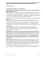
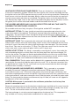
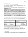
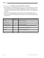
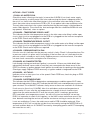
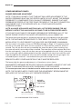
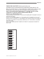
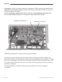
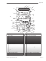
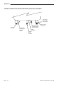
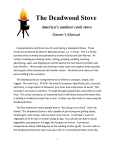
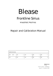
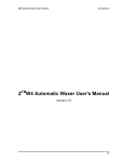
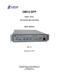
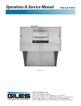
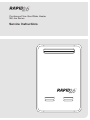
Continuous Flow Gas Water Heater
26 Litre Series
Service Instructions
Rapid 26
Rapid Continuous Flow Gas Water Heater
26 Litre Series
Service Instructions for:
Natural Gas
Propane Gas
RAPID R26P
RAPID R26N
This manual covers the normal servicing required
on the above models.
KEY TO MODEL NUMBERS
R=RAPID
26 = 26LPM @ 25ºC temperature rise.
N = Natural Gas
P = PROPANE Gas (Australia only, not universal LPG)
Alliance Appliances Pty Ltd
Page 1
Rapid 26
26LPM CONTINUOUS FLOW
HOT WATER SERVICE MANUAL
DESCRIPTION OF OPERATION
The Rapid 26 range of Continuous Flow Gas Hot Water Services (CFGHW) are Gas fired
Forced combustion hot water heating appliances.
The unit is powered and active at all times. When hot water is required, signalled by turning
on a hot tap in the home (to the desired flow rate), the unit senses flow via the flow meter,
and after some safety checks initiates an ignition cycle.
IMPORTANT: THE WATER FLOW RATE WILL BE AUTOMATICALLY REDUCED
MOMENTARILY TO ENSURE FAST HEAT UP AND TO MINIMISE WATER WASTAGE.
When the water approaches the correct temperature the unit will then resume the
desired flow.
If there is air in the line or for some reason ignition does not occur, the controller attempts
again for 5 more attempts. It will then lock out. The unit is reset only when the water is
turned off for 2 seconds and then back on again. Switching the power off and on again,
without interrupting the water flow, will NOT reset the unit. Only when the tap is closed
and opened again will the ignition cycle be re-started.
After a successful ignition attempt, and immediately the unit senses flame at the burners,
the control unit (ECU) calculates how much gas is needed to ensure that the water is at the
correct temperature for that flow rate. It then switches on 1, 2 or 3 packs of burners using
3 solenoids provided. As well the ECU unit polls the outlet temperature sensor many times
per second and fine tunes the gas flow via a gas modulating valve. This valve is the blue coil
on top of the main gas control valve. The unit adjusts the gas to suit the water flow and the
desired temperature, thereby supplying water at the correct temperature.
The unit also reacts to changes in flow rate, (e.g. another tap being turned on) and starts to
re-adjust the temperature almost immediately.
If the desired temperature cannot be attained because the user has opened water taps
too far or has too many on at one time, (Excessive flow rate) the unit will adjust the water
flow down internally so that the desired temperature will be maintained. (This is called
Temperature Priority).
The unit also includes a safety shut down if the water gets too hot, which requires a
water flow shutdown and reopening of a tap to reset. This fault however is not common and
indicates a problem with the unit. If it recurs call a service agent to correct the fault.
Also included is a safety shutdown and re-ignition if the sensor loses flame contact during
use. It repeats this 5 times and then locks out. Reset is again by a 2 second interruption to
water flow.(Turn tap off and then on after 2 seconds.
Alliance Appliances Pty Ltd
Page 3
Rapid 26
COMPONENTS DESCRIPTION
GAS TRAIN AND CIRCUIT
1.GAS VALVE. This valve is a SIT Components 845 Sigma model with 2 main solenoids and
an additional (Blue, low voltage) ) Modulating Valve to adjust gas rate for fine adjustment.
The Rapid unit has a special inlet fitting provided with a gas test point that is fitted outside
the case underneath the unit to allow for easy checking of the inlet gas pressure. The gas
outlet (burner) pressure is easily read using the gas manifold test point provided on the
front of the burner box assembly.
2.VALVE TO BURNER PIPE. This is a short copper pipe formed to transmit gas from the gas
valve outlet to the gas manifold which is integrated into the burner box assembly. The pipe
uses flat rubber washers at each end for gas sealing.
3.THE GAS MANIFOLD is a cast component that has a stamped plated steel cover and
gasket and distributes gas to 3 separate Solenoids (Fig A Item 3). These solenoids deliver
gas to the packs of 3, 5 or 9 of the 17 burners, plus a combination giving 3,5,8, 12 and
17 burners. The solenoids, under the control of the main electronic controller, (ECU Fig
A) allow rough cut supply of gas to approximately suit the desired temperature and water
flow. The modulating valve as described in point 1 above, is also under the control of the
ECU and allows fine tuning of the gas pressure at the burner injectors to precisely match
the desired load. A multi stepped gas rate is therefore provided. There is provided a gas
pressure test point on the manifold for checking of burner gas pressure.
4.BURNERS There are 17 small burners in the unit and these are made of stainless steel
and would normally not need servicing.
5.GAS INJECTORS are located in the cast alloy manifold and can be accessed after
removal of several screws. See instructions.
6.HEAT EXCHANGER The hot gases from the burner array pass vertically upward through
a box type copper heat exchanger which has helical cold water pipe soldered to the
outside of it. This scavenges heat and supplies pre-warmed water to the main finned heat
exchanger. Across the top of this box there is a finned copper serpentine heat exchanger
that takes most of the energy from the flue gases and transfers it to the water flowing in
the pipes, prior to the cooled gases being exhausted from the stainless steel flue outlet.
WATER CIRCUIT
7.INLET WATER FITTING. This fitting is connected to the cold inlet mains water (or the
warm outlet of a Solar Pre-heater tank. (70C model only.)) It has a screw off combination
filter/drain fitting that incorporates a stainless gauze water filter. Only under extreme
conditions is this filter expected to become blocked. The drain is useful for draining the
unit if it is to be left in a cold area with no power available. (Freeze Protection.) This fitting
also has pockets for the inlet water temperature sensor and a small heating resistor for
freeze protection.
Page 4
Alliance Appliances Pty Ltd
Rapid 26
8.INLET WATER VALVE. This valve is located just inside the case bottom and is an extension
of the inlet water fitting. It is electrically controlled by the ECU to adjust the flow rate of the
water so that the desired temperature can be achieved even if the user has fully opened
up several taps.(Thereby exceeding the possible heat input from the unit.) The inlet water
valve also incorporates the flow sensor turbine that allows the ECU to detect water flow
above 3LPM and initiate the ignition cycle. The flow meter also provides information to the
ECU to finely adjust the gas to give the desired temperatures. The outlet of this valve is
connected to the inlet pipe of the copper heat exchanger described above.
9.HEAT EXCHANGER. This as described above in (6).
10.OUTLET WATER FITTING. This is located under the lower left hand side of the heater
and incorporates a pressure relief valve and drain assembly. It connects with the outlet
pipe of the heat exchanger and is connected through the case to the delivery pipe into
the house.
ELECTRICAL COMPONENTS
11.ECU. This is located at the lower left hand front of the unit and has all the electronics
needed to control the gas and electrical components to ensure ignition, temperature
and safety aspect all perform as designed. The electronic components should never be
touched by hand as static electricity can destroy the electronics.
12.SENSORS. Water TEMPERATURE. There are 2 temperature sensors, one in the
incoming water valve and one in the outgoing water fitting. These are wired back
and plug into the PCB. Each has an O-ring and small screw bracket.
13.TRANSFORMER. MAINS POWER SUPPLY. There is provided a mains power
transformer to supply all the electrical loads required for the various components.
14.PRESSURE SWITCH. Fan Proving. This is located at the lower RH end of the case
and is connected via a silicone rubber tube to the fan outlet. This switch senses fan
air pressure and allows the ECU to ignite the unit in the knowledge that the fan is
operational. The other side of the pressure switch is connected to a short hose that
connects with the air inlet vents to balance the air switch under wind conditions.
15.FAN (COMBUSTION). This is approx 100 mm diameter and is located behind the ECU
PCB. It is mounted from the bottom of the burner box assembly. The fan assembly can
only be removed after the heat exchanger is removed. However, the fan motor and fan
wheel component can be removed from the fan scroll by removing 3 screws visible on
the front of the fan assembly, saving much disassembly to change a fan over..
16.OVER-TEMPERATURE CUT OUT. This is fitted at the top RH side of the heat exchanger
on the pipe work and is of the auto reset type. This will only open circuit if the main ECU
fails to operate properly. WARNING: THIS ITEM IS CONNECTED TO 240V MAINS
POWER AT ALL TIMES.
Alliance Appliances Pty Ltd
Page 5
Rapid 26
17.ANTIFREEZE. This is an array of ceramic power resistors IN SERIES which are clipped
onto the water carrying pipes or are imbedded into the water valves and fittings. They are
all connected with fibreglass wiring and are 240V MAINS POWERED AT ALL TIMES,
providing the unit is plugged in and power switch is on.
The frost sensor is attached to the outlet of the heat exchanger at the top LH side of
the unit. It is recommended that power be left on to this unit even when the home is
vacant, (such as at holiday time) to ensure that the risk of damage from frozen pipes and
components is minimised.
CAUTION: Power must be applied at all times for this heater circuit to effectively
protect the unit in frosty conditions.
18. DRAIN The unit can be drained (if it is desired to switch off all power to the unit)by
removing the inlet water filter AND the outlet pressure relief valve on the hot water
outlet fitting.
19. THERMAL FUSE. A thermal fuse is fitted on the rear of the heat exchanger in a fiberglass
sleeve. This must only be replaced with a genuine part from Alliance.
Page 6
Alliance Appliances Pty Ltd
Rapid 26
SERVICING THE UNIT
DISASSEMBLY OR REMOVAL OF COMPONENTS.
CAUTION: ENSURE ALL WATER, POWER AND GAS SUPPLIES ARE ISOLATED PRIOR TO
REMOVING FRONT COVER.
FRONT COVER. This is removed after removal of 2 screws at the top flange and 2 at the
bottom flange. The cover lifts straight off but care must be taken to not break or lose the thick
rubber gasket from around the flue spigot at the top. If it comes off retain it and ensure that
it is refitted upon re-assembly. A balance tube is fitted between the pressure switch and the
front cover, care must be taken to replace this tube if disconnected.
CAUTION: The unit will NOT perform correctly without the front cover and balance pipe
in place.
MAIN CONTROL PCB. Remove all plugs, wires and ignition cable and remove 2 screws
from underneath the unit and the PCB, in its box ,will come out of the unit. All plugs are
polarised and are different so re-assembly is straightforward. The cold water sensor and
hot water sensors are combined into a 4 pin plug to avoid errors. The individual sensors
are connected to the 4 way plug with 2 polarised in line connectors with different polarity to
avoid mix ups.
TRANSFORMER. The main power transformer is secured by 2 screws through the
case. All low voltage connections are already disconnected but 240V connections must
be disconnected prior to removal/replacement. Refit unit in reverse order ensuring all
connections are correctly made.
INJECTORS. If access to the gas injectors is required the gas manifold must be removed.
DO NOT REMOVE THE FRONT PLATED STEEL COVER AS THIS IS PART OF THE GAS
TRAIN. Note position of wiring to the 3 solenoids and disconnect. Undo the main brass nut
at the manifold end of the valve to burner pipe and ensure that the flat washer is not lost.
Remove the gas manifold taking care to not damage the rubber sealing strips that seal the
manifold to the burner box. Re-assemble to burner box in reverse order. ENSURE THAT
IGNITION WIRE AND FLAME SENSOR WIRES ARE STILL CONNECTED. Re-connect
solenoid wires.
MAIN GAS VALVE. ENSURE GAS IS OFF at the isolating valve. Unplug 2 wires from the
blue modulating coil on the front of the gas valve. These are not polarised and can go on
either way. Unplug the main wiring connection from the gas valve body. Remove the Union
from the gas inlet isolating valve and remove the combination gas fitting /gas pressure test
point. Remove 2 screws adjacent to the inlet gas spigot. Remove the valve to burner pipe
ensuring that the flat rubber gasket is not lost. Remove Gas valve.
Reassemble in reverse order ensuring that all gaskets and sealing rings are in place and all
wiring connections are well made. Adjust gas valve settings as per instructions below.
Alliance Appliances Pty Ltd
Page 7
Rapid 26
IGNITION ELECTRODE AND FLAME SENSOR. These are located on a small plate at the
front of the combustion chamber. Remove the thick ignition wire from the electrode and from
the ignition coil on the PCB to prevent excessive strain on the wiring connection. Remove the
flame sensor wire from the other electrode. Mark or otherwise ensure that the wires go back
onto the correct electrode when re-assembled. The ignition lead is on the left looking at the
unit. Remove the single screw at the centre of the plate and gently remove the plate, ceramic
felt gasket, the 2 ceramic electrode holders and the electrodes from the unit.
THE HOLDERS ARE KEYED AND CAN ONLY BE RE-FITTED ONE WAY. TAKE CARE TO
ASSEMBLE THE ELECTRODES CORRECTLY.
Re-assemble and screw firmly into place. Check gasket and do NOT over-tighten.
WATER INLET FITTING. This item should not need to be removed except where the inlet
water valve needs to be replaced. The fitting is removed (after disconnecting the water
supply pipe,) by removing 2 screws through the flange on the fitting from underneath the
unit. The fitting will then separate from the inlet valve inside the unit. DO NOT LOSE THE “O”
RING or damage the sensor.
WATER INLET VALVE. This incorporates the motorised valve and the water flow sensing
turbine. After removal of the inlet water fitting, undo 2 screws from underneath the unit case
and also 2 screws that retain the valve to heat exchanger cold water pipe. The valve should
then lift out. Take care to not lose the “O” Ring. The cold water sensor also fits into the side
of this valve with a screw and small plate. It has a mall O ring to seal.
WATER OUTLET FITTING. This fitting is removed by removing the 2 screws from under the
unit and undoing the brass nut that retains the hot water pipe from the heat exchanger. Do
not lose the washer. The pipe can then be pushed backwards out of the way and the fitting
removed. Note that this fitting also has a pocket for a frost protection resistor and also water
outlet sensor. A single screw and bracket hold both the sensor and the heater.
FAN, COMBUSTION. The fan motor and fan blade of this component can be removed by first
removing the 3 screws that hold the motor to the fan scroll. This is the most convenient way
to replace the fan if faulty. The fan scroll itself can only be removed after the heat exchanger
and burner box assembly is removed.
HEAT EXCHANGER (AND BURNER BOX) ASSEMBLY. This is removed as a complete
assembly. Disconnect/ Unplug all connections and remove PCB by removing 2 screws
from under the outer case , Disconnect and remove valve to burner pipe, transformer, and
disconnect overtemperature sensor on top RH corner, disconnect anti frost connections from
mains terminal block, and water connections from Cold inlet water valve and Hot water outlet
fitting. The frost protection heaters and thermostat (top LH side) will come out still clipped to
the pipework of the heat exchanger.
CAUTION: Mains power is connected to the antifreeze protection circuit at any time
power is connected to unit.
Remove 4 mounting screws from the brackets under the gas manifold and 4 screws from the
brackets either side of the flue outlet at the top, and lift heat exchanger assembly free of the
case. The fan scroll and fan motor will came out as part of this assembly.
The heat exchanger is not to be serviced separate from the burner box. This component is
only available as a factory sealed and assembled unit for safety reasons.
Page 8
Alliance Appliances Pty Ltd
Rapid 26
DIAGNOSING FAULTS.
The most common complaint will be “NO HOT WATER”.
NOTE: THE UNIT WILL NOT OPERATE CORRECTLY UNLESS ADEQUATE GAS AND
WATER PRESSURE IS AVAILABLE.
WITH ALL GAS APPLIANCES IN THE HOME RUNNING AT MAXIMUM THERE MUST BE
adequate pressure at the ALLIANCE UNIT INLET GAS PRESSURE TEST POINT at the
gas connection to the unit.
The required pressure is 1kPa- 3kPa for natural gas, and 2.75kpa-3kPa for Propane
Gas.
SERVICEMAN: USE A MANOMETER TO CHECK THIS REQUIREMENT FIRST. There is
provided a gas inlet pressure test point on the special fitting provided at the gas inlet
connection external to the outer case bottom.
LOW GAS PRESSURE IS A MAJOR SOURCE OF COMPLAINTS REGARDING NO HOT
WATER. If insufficient pressure is available, advise the customer to contact the installer.
The supply utility will generally upgrade the meter but undersize piping will be the owner’s
responsibility.
ALLIANCE APPLIANCES WILL NOT BE LIABLE FOR ANY WARRANTY/ SERVICE COSTS
IF GAS PRESSURE IS FOUND TO BE INADEQUATE.
In addition, in the event of “NO HOT WATER”, it is imperative to check if POWER is present
at the power outlet, GAS is available and is of adequate pressure and that there is a good
supply of WATER flowing from a hot tap in the house. (3 Litres Per Minute MINIMUM.)
SYMPTOM
POSSIBLE CAUSE
HOW TO DIAGNOSE
REMEDY
No Hot Water
No Power
Check power outlet
with meter.
Correct power supply
No Hot Water
No Gas
Correct Gas supply
to Specification
No Hot Water
No Water Supply
Correct water supply
to the specifications.
After checking all of these requirements, attempt to start unit again.
If unit does not respond at all (dead) it indicates that there is a power disconnect
somewhere. If the unit tries to start, (e.g. fan runs, igniter attempts to spark etc. but then
shuts down it indicates that the Power is On, and the PCB/ECU is operating but either
the gas is not available, or there is air in the lines. Purge the line again and/or retry. IF not
successful, it will become necessary to access the inside of the unit.
1.Switch off power
2.Remove front cover. Be careful to disengage the pressure switch balance hose from the
front cover.
Alliance Appliances Pty Ltd
Page 9
Rapid 26
3.Switch power ON. WARNING: SOME COMPONENTS ARE AT 240V.
4.Check for power at the PCB by observing if there are any LEDS illuminated. If not, check
fuse on PCB lower LH side. Check 240V overtemperature cutout at top RH corner. This
is auto reset and may have reset already. If LEDS are not on and fuse is OK then either a
connection from the transformer is disconnected or the transformer is unserviceable.-Test
and replace.
5.If LEDS are visible, (cover off) turn on a hot tap and allow unit to attempt to start. If it
does not start, observe amber flashing LED at top centre of PCB. The LED will flash on
and off in a series of either 1 flash or 2 or 3 etc. Cross check with the chart below to help
isolate the fault.
FLASHES
No Flow
1
Flow between 0-2LPM
Temp error inlet
2
Open/short circuit sensor
Temp error outlet
3
Open/short circuit sensor
Pressure Switch Fault
4
If there is FAN ON and pressure switch didn’t activate
No Flame
5
No Flame Signal received after start
No Tacho
6
No fan tacho signal received
Overtemp
7
If temperature goes over set temp +20’C
Page 10
Alliance Appliances Pty Ltd
Rapid 26
ACTIONS – FAULT CODES
1 FLASH- NO WATER FLOW.
Check that water is flowing at hot tap(s) at more than 2.5LPM. If not check water supply
at inlet to heater by cracking water inlet union and ensuring that there is adequate water to
the unit. If so, check inlet water filter/strainer in the cold water inlet water fitting. If clean,
check that water valve connection to PCB is OK. If not replace inlet water modulator valve.
The only other restriction in the system could be that the heat exchanger is blocked due to
water solids deposits. Flow check the heat exchanger Min flow should be 3LPM with one
tap opened.. If blocked, clean or replace.
2 FLASHES – TEMPERATURE ERROR- INLET.
This indicates that the inlet temperature sensor in the inlet water valve fitting is either open
circuit, short circuit or not plugged in to the PCB or is plugged into the incorrect receptacle
on the PCB. Check and/or replace as required.
3 FLASHES- TEMPERATURE ERROR- OUTLET
This indicates that the outlet temperature sensor in the outlet water valve fitting is either open
circuit, short circuit or not plugged in to the PCB or is plugged into the incorrect receptacle
on the PCB. Check and/or replace as required.
4 FLASHES - PRESSURE SWITCH/FAN.
If the fan runs this indicates that the pressure switch is faulty. Check if silicone tube from Fan
to pressure switch is in place and is not leaking. If the fan does not run it indicates that the
pressure switch is already on and is faulty. Replace pressure switch and retest, if fan does
not start check connections and replace fan if necessary.
5 FLASHES- NO FLAME DETECTED.
Look through viewing port and see if ignition is successful. If flames are visible briefly then
extinguishes the flame sensor cable is most likely not connected to the flame sensor or the
PCB. If no flames or ignition attempt check ignition wire and listen for sparking at the electrode.
Check gas supply. Replace PCB if necessary as ignition module is integrated into the PCB.
6 FLASHES – NO TACHO.
Indicates no fan on start up or loss of fan speed. Check PCB fuse, check fan plug on PCB.
Replace fan as required.
7 FLASHES- OVERTEMPERATURE.
This indicates that the PCB has detected an overtemperature condition approx 20ºC hotter
than the desired setting. It does NOT indicate that the 240V main overtemperature cut out has
open circuited. This would NOT indicate a faulty sensor as these are covered in 2 & 3 above.
If unit runs at a flow of say 5-10LPM, allow it to settle down and record temperature at
nearest outlet. If it runs over the set temperature for a length of time it should cut out
again when the outlet reaches 20ºC over the set point, but if it continues passed that
ECU controlled over temperature control, the unit will cut out on the 240V cut-out top
RHS. It is imperative to check if this happens, as the 240V cutout would have reset in the
time between receiving the service call and the serviceman arriving to service the unit. If
it cuts out and flashes 7 times, the outlet sensor and/or PCB should be replaced. (Over
temperature of 20ºC will cut out the unit but it can be reset by turning the WATER off for 2
seconds and then back on. It CANNOT be reset by interrupting power and NOT interrupting
the water flow as well.)
Alliance Appliances Pty Ltd
Page 11
Rapid 26
OTHER IMPORTANT POINTS
BURNER PRESSURE ADJUSTMENT
NOTE: IT IS HIGHLY UNLIKELY THAT THIS UNIT WILL NEED ADJUSTMENT IF THE
SUPPLY PRESSURE IS WITHIN THE STATED LIMITS. DO NOT ADJUST THE BURNER
PRESSURE TO COMPENSATE FOR LOW INLET PRESSURE. ENSURE THAT INLET
PRESSURE IS TESTED AT THE TEST POINT PROVIDED AT THE INLET CONNECTION
AND ENSURE THAT IT IS CHECKED WITH ALL OTHER GAS APPLIANCES
OPERATING AT MAX.
NOTE: ALLIANCE APPLIANCES AUSTRALIA WILL NOT BE RESPONSIBLE FOR ANY
SERVICE COSTS IF THIS GAS SUPPLY IS FOUND TO BE OUTSIDE STATED LIMITS.
IF THE UNIT IS NOT ABLE TO BE MADE OPERABLE BY EXERCISING ALL OF THE
ABOVE PLEASE CONTACT ALLIANCE APPLIANCES Pty Ltd on 0438397143
The burner pressure test point is located on the main gas valve adjacent to the gas outlet.
NOTE: THE UNIT MUST BE SWITCHED TO TEST MODE TO CANCEL THE WATER
MODULATION TO HELP ENSURE THAT HIGH FIRE GAS PRESSURE IS MAXIMUM.
The test switch is located as shown on PCB Board Image on Page 14. To operate, power
the unit on. No water flow. Allow 10 secs of power on. Press the test switch for at least 1
second. This will not allow the unit to modulate the water flow down. After checking, turn
the water off and this test mode will be cancelled. The water flow will be maximum but if less
than the unit capacity, it may still not allow max gas to be applied to the unit. If this is the case
you can only get a quick sample period of max gas when the unit starts from cold. Run cold
water through the unit with power off to cool unit to enable startup with max gas again. You
will need to press switch for 1 second each time you want to test pressure.
REMOVE PLASTIC COVER AND RETAIN IT AS IT MUST BE REPLACED.
The burner high fire pressure adjustment is a 10mm brass nut as shown.
MANOMETER TUBE MUST BE ROUTED THROUGH GROMMET IN BASE OF UNIT AND
FRONT COVER MUST BE IN PLACE FOR READING TO BE ACCURATE.
To increase pressure turn nut clockwise and to reduce pressure turn nut anticlockwise.
NOTE: THE CLEAR PLASTIC COVER OVER THE ADJUSTMENT SCREWS MUST BE
REPLACED OR THE UNIT WILL NOT OPERATE PROPERLY.
PCB BOARD
BURNER
PRESSURE
TEST POINT
SIT VALVE
10mm BRASS NUT
(High Fire Pressure Adjustment)
INLET
PRESSURE
TEST POINT
26L GAS PRESSURE TEST POINTS
Page 12
Alliance Appliances Pty Ltd
Rapid 26
TEMPERATURE ADJUSTMENTS. (By licensed installers only)
The Rapid 26 can be incrementally preset to temperatures between 50ºC to 74ºC.
When pre-set to 50ºC there is a range of adjustment available to the installer to ensure
that the outlet nearest the heater can be increased to make up for pipe losses.
NOTE: IT IS THE INSTALLER’S RESPONSIBILITY TO ENSURE THAT ANY OUTLET
CONNECTED TO THIS UNIT CANNOT DELIVER WATER OVER 50C .
SELECTION OF TEMPERATURE AT 50ºC
THIS ADJUSTMENT IS PROVIDED TO ALLOW THE INSTALLER TO ENSURE THAT 50ºC
WATER IS AVAILABLE.
NOTE: IT IS THE RESPONSIBILITY OF THE INSTALLER TO ENSURE THAT NO HOT
WATER OUTLET ATTACHED TO THIS VERSION CAN DELIVER WATER IN EXCESS OF
50ºC DUE TO THE RISK OF SCALDING, ESPECIALLY OF THE ELDERLY, CHILDREN
AND THE INFIRM.
NOTE: THE POWER MUST BE TURNED OFF PRIOR TO CHANGING THIS SET OF
SWITCHES.
3 2 1
50C
3 2 1
53C
3 2 1
55C
3 2 1
58C
3 2 1
60C
3 2 1
63C
3 2 1
65C
3 2 1
74C
Alliance Appliances Pty Ltd
Page 13
Rapid 26
Connections. Check all visible connections and plugs on PCB, especially the ignition spark
cable (8mm spark plug type cable) and the flame sensing cable, both of which run from the
PCB to the ignition electrodes.
NOTE: THE SPARK CABLE IS FITTED TO THE LEFT HAND SIDE ELECTRODE AND
THE FLAME SENSOR CABLE TO THE RIGHT HAND SIDE ELECTRODE.
Temperature Adjustment
Maximum Gas Switch
PCB Board: temperature switches and max gas push button.
The maximum gas button prevents the unit from decreasing the water flow and gas rate.
Push once for about 1.0 second, and it will prevent water modulation until the water is turned
off . It can only hold gas at max for a few seconds. It reverts to normal when flow rate is zero.
It is used to ensure maximum water flow to enable maximum gas pressure to be monitored
and reset if required.
If not pushed the unit will decrease gas pressure and give an incorrect reading on
manometer.
Page 14
Alliance Appliances Pty Ltd
Rapid 26
3
2
1
4
5
6
7
8
9
10
36
31
9
11
11
12
13
15
35
33
34
16
14
17
18
19
37
30
20
29
28
22
23
21
32
24
25
27
26
No.
Component
No.
Component
1
Case - Outer
20
Valve - Water Outlet Assembly
2
Outlet - Flue
21
Valve - Pressure Relief and Drain
3
Gasket - Flue Outlet
22
Connection - Hot Water Out
4
Thermostat - Frost protect
23
Valve - Water Control and Flow Sensing
5
Heat Exchanger - Main
24
Connection - Cold Water Inlet
6
Thermostat - Overtemp
25
Plug - Outlet Filter and Drain
7
Heater - Frost Protection
26
Fittings - Gas Inlet Special
8
Electrode - Spark Ignition
27
Spiggot - Gas Inlet Pressure test
9
Window - Inspection
28
Valve - Gas Main Control
10
Burner Box
29
Valve - Gas Modulation (Blue Coil)
11
Screw - Manifold Attachment
30
NUT - Burner Pressure Adjustment
12
Cover - Gas Chest
31
Electrode - Flame Sensing
13
Solenoid(s) - Burner Pressure Test
32
Pressur Switch - Air Proving
14
Spiggot - Burner Pressure Test
33
Hose - Pressure Switch Comb Chamber
15
Pipe - Valve to Burner
34
Hose - Combustion Chamber Compensation
16
Transformer - Power Supply
35
Hose Front Cover Compensation
17
Motor Assembly - Comb Fan
36
Pressure Tapping - Combustion Chamber
18
Screw - Fan Motor Retaining
37
Pressure Tapping - Gas Valve Compensation
19
PCB - Control (Outline)
Alliance Appliances Pty Ltd
Page 15
Rapid 26
WATER CONNECTION, FILTER AND DRAIN DETAILS ALL MODELS
GAS INLET
PRESSURE
TEST POINT
OUTLET
FITTING
PRESSURE
RELIEF VALVE
REMOVE
DRAIN
REMOVE CAP TO
CLEAN FILTER
AND TO DRAIN
GAS INLET
ADAPTOR
FILTER
ASSEMBLY
WATER
INLET
FITTING
Page 16
Alliance Appliances Pty Ltd
Rapid 26
Alliance Appliances Pty Ltd
Page 17
83 JELLS ROAD WHEELERS HILL VIC 3150
T 0438 397 143 E [email protected]
www.allianceappliances.com.au