1
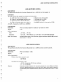
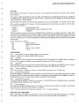
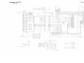
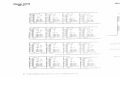
1
1
1
SYSTEM SCHEMATICS
A2091
DECEMBER, 1989
PN-314674-01
1
INTERNATIONAL EDITION
COMMODORE "INTERNATIONAL EDITION" SERVICE MANUALS CON
TAIN PART NUMBER INFORMATION WHICH MAY VARY ACCORDING TO
COUNTRY. SOME PARTS MAY NOT BE AVAILABLE IN ALL COUNTRIES.
n
Commodore Business Machines, Inc.
1200 Wilson Drive, West Chester, Pennsylvania 19380 U.S.A.
n
Commodore makes no expressed or implied war
ranties with regard to the information contained
herein. The information is made available solely on
an as is basis, and the entire risk as to quality and
accuracy is with the user. Commodore shall not be
liable for any consequential or incidental damages
in connection with the use of the information con
tained herein. The listing of any available replace
ment part herein does not constitute in any case
a recommendation, warranty or guaranty as to
quality or suitability of such replacement part.
Reproduction or use without expressed permission,
of editorial or pictorial content, in any matter is
prohibited.
This manual contains copyrighted and proprietary information. No part
of this publication may be reproduced, stored in a retrieval system, or
transmitted in any form or by any means, electronic, mechanical,
photocopying, recording or otherwise, without the prior written permis
sion of Commodore Electronics Limited.
n
Copyright © 1989 by Commodore Electronics Limited.
All rights reserved.
1
A2091 SYSTEM SCHEMATICS
il
H
1
1
R
1
H
n
n
n
n
TABLE OF CONTENTS
• SPECIFICATIONS
PARTS LISTS
SCHEMATICS
NOTE
PLEASE REFERENCE A2091 USER MANUAL
PN-363227-02 FOR DETAILED OPERATIONS.
A2091 SYSTEM SCHEMATICS
n
n
A2091-40 SPECIFICATIONS
DESCRIPTION
This specification describes the Functional Requirements for an A2091-40 hard disk upgrade kit.
CONTENTS
The A2091-40 hard disk upgrade kit contains the following items:
A. A2091 Hard disk controller board
n
E. Shock mounts for hard drive
B. Cables for card-mounting hard disk drive
F. Stiffening rod for A2000
C. Quantum pro-drive 40S hard disk drive
G. Foam pad for A2000
D. Cable for mounting hard drive in drive bay
H. A2000HD sticker for front panel of A2000
An A2091-40 upgrades an A2000 to an A2000HD.
PARAMETERS
n
n
Dimensions:
PCB 13.25 inches; Hard drive 6 inches by 4.25 inches by 2 inches
Weight:
5 lbs.
Power requirements:
PCB:
+12V 0.0A, +5V 1.0A
Hard drive:
+ 12V 1.6A, + 5V 0.7A Power up; + 12V 0.8A, +5V 0.6A Normal operation
Hard drive features:
42 MB formatted capacity; 19 ms seek time; supports disconnect/reselect; 64K byte lookahead cache; 1:1 interleave
A2091 SPECIFICATIONS
DESCRIPTION
This specification describes the Functional Requirements for an A2091 hard disk controller assembly.
PARAMETERS
n
Dimensions:
PCB 13.25 inches by 5 inches
Weight:
1 1b.
Power Requirements:
Without a hard drive mounted to card:
+ 12V 0.0 A
+ 5V
1.0 A
With hard drive mounted to card:
+ 12V 2.5 A max startup, 0.9 A max continuous
+ 5V
Features:
2.5 A continuous
Hard disk controller for SCSI or XT style drives; Sockets for up to 2 MByte fast RAM;
Auto-boot ROMs; Boots directly into Fast File System; Rear socket permits connection
of Macintosh style SCSI expansion devices; Space on card to mount user's own 3.5" hard
drive
n
n
A20P1 SYSTEM SCHEMATICS
JUMPERS
JP1 is used to set the amount of memory on the board. It has 4 positions that represent no memory, 512K, 1M and
2M of memory.
n
H
JP2 is used to enable and disable the auto-boot ROMs. The ROMs must be disabled when the board is installed in
an A2000 with KS1.2 ROMs. The position marked "AUTO" enables the auto-boot ROMs and the position marked
"DIS" disables the autoboot ROMs.
JP3 determines the interrupt level that the board generates and is not user adjustable. It is factory wired to INT2.
JP5 is a software readable set of 3 jumpers. The function depends on the driver software, but with V4.4 of the driver
the function is as follows:
Jumper 1:
Enable Multiple LUNs
Jumper 2:
Enable long boot timeout, disable parity check
Jumper 4:
Undefined
JP201 determines the clock rate fed into the WD33C93 SCSI controller IC. It is factory wired for a 7 MHz clock
n
rate and is not user adjustable. If an end user would like to replace the standard WD33C93 with a high speed version
of the part, the trace between the upper 2 pins of JP201 can be cut, and the lower 2 pins wired together. This would
result in a 14 MHz clock rate which would effectively double SCSI throughput given a hard drive that can operate
at that speed.
Factory settings are as follows:
i
JP1
OK (no memory)
JP2
DIS (Autoboot disabled)
JP3
INT2
JP5
ALL 3 functions disabled
JP201
7 MHz
CONNECTORS
CN1
(Not labeled on board) 100 pin Amiga edge card connector
Designed to plug into a standard A2000 100 pin Amiga slot.
CN2
XT LED
This is designed to accept the plug from the hard disk LED on the front panel of the A2000 if the user is using an
XT drive. This connector will light the front panel LED whenever the XT drive is accessed.
1
n
CN3
SCSI LED
This is designed to accept the plug from the hard disk LED on the front panel of the A2000 if the user is using a
SCSI drive. This connector will light the front panel LED whenever any SCSI device is accessed.
CN4
XT drive connector
This 40 pin connector is designed to attach to a ribbon cable that connects to an XT hard drive.
CN5
External SCSI connector
This DB25 connector is designed to connect the A2091 to external SCSI devices. It uses a pinout identical to the Apple
Macintosh (R) SCSI connector and has the capability of connecting to any peripheral that is designed to connect to
the Macintosh (R). Up to 7 external devices may be connected by daisy-chaining.
CN6
Internal SCSI connector
This 50 pin header is designed to attach to 1 or more (up to 7) internal SCSI devices. Multiple devices are connected
by crimping multiple connectors onto 1 ribbon cable.
CN7
Power connector
This 4 pin molex connector supplies power to a 3.5" hard drive that the user may install on the A2091. The maximum
power that may be drawn from this connector is as follows:
+ 12V: 2.5A max startup (8 sec), 0.9A max continuous; +5V: 1.5A max continuous
MOUNTING OF HARD DRIVE
Space is provided on the A2091 for the end user to mount a 3.5 inch hard drive. Mounting hardware is not included,
and a cable is required to allow the hard drive to draw its power from the A2091, CPN 312646-01.
H
A2091 SYSTEM SCHEMATICS
A2091 MAJOR PARTS LIST
n
n
n
n
n
n
r
313441-01
A2091-40 SHIPPING ASSEMBLY-U.S.
313441-02
A2091-40 SHIPPING ASSEMBLY-GERMANY
313441-03
A2091-40 SHIPPING ASSEMBLY-EFIGS.
313441-04
A2091-40 SHIPPING ASSEMBLY-SCANDI.
313441-05
A2091-40 SHIPPING ASSEMBLY-CANADA
313441-06
A2091-40 SHIPPING ASSEMBLY-AUSTRALIA
363243-01
BULK PACKING BOX
363242-02
PACKING BOX
318900-01
WARRANTY CARD U.S.
318882-01
WARRANTY CARD CANADA
318884-01
WARRANTY CARD AUSTRALIA
314877-02
SERVICE CENTER LIST U.S.
363033-01
A2091 USER MANUAL - EFIGS
363034-01
A2091 USER MANUAL - SCANDI
363227-02
C
252253-12
A2091 USER MANUAL - ENGLISH
PLASTIC BAG
317806-01
C
DISKETTE - INSTALL (US)
317807-01
C
DISKETTE - INSTALL (GER)
318896-01
SOFTWARE LICENSE U.S. & CANADA
312341-02
DISKETTE REPLACEMENT CARD (US)
318556-02
DISKETTE REPLACEMENT CARD (CANADA)
312773-01
A2091 MAIN ASSEMBLY
312778-01
BRACKET, MOUNTING (ON MAIN ASSY)
906610-01
SCREW PHILIPS 6-32 (QTY = 4, MAIN ASSY)
905970-04
C
316754-01
NUT, KEPS 6-32 (QTY = 8, 4 ON MAIN ASSY, 4 FOR HD MOUNT)
UPC LABEL
312646-01
C
CABLE, POWER
312573-01
C
CABLE, DATA 50P SHORT
313439-01
C
CABLE, DATA 50P LONG
313440-01
C
DRIVE, HARD 40MB SCSI QUANTUM
312713-01
C
TIE BAR
312748-01
C
ISOLATOR, VIBRATION
311554-01
C
NAMEPLATE (AMIGA 2000HD STICKER)
312749-01
C
FOAM SUPPORT
907272-02
C
WASHER, FLAT
905960-04
C
NUT, HEX M3
312769-01
C
A2091 PCB ASSEMBLY - REV 4
312770-01
SCHEMATIC - PCB REV 4
312771-01
FABRICATION - PCB REV 4
312772-01
ARTWORK - PCB REV 4
n
A2091 SYSTEM SCHEMATICS
n
n
n
n
n
n
COMPONENT PARTS LIST
PCB ASSEMBLY #314386-03
Commodore part numbers are provided for reference only and do not indicate the availability of parts from Commodore.
Industry standard parts (Resistors, Capacitors, Connectors) should be secured locally. Approved cross-references for TTL chips,
Transistors, etc. are available in manual form through the Service Department, order #314000-01.
IC COMPONENTS
390333-03
16L8A RAM CONTROLLER
RESISTORS
U5 PROGRAMMED
901550-105 33 OHM 1/4W
R1,3,9-11
INTO P/N 390071-02
901550-01
1 K OHM 1/4W
R2,4,6,8,101
390332-01
74F158A
U8.U9
90155049
100 OHM 1/4W
R12
901521-46
74LS245
U2,U3
901550-131
56 OHM 1/4W
R7
390563-02
DMAC
Ul
380388-04
220/330 OHM/10PIN/8 ELEMENTS/SIP
RN1.RN3
390206-01
WD33C93
U4
220/330 OHM/6PIN/4 ELEMENTS/SIP
RN2
901522-30
7407
U7
380388-01
390227-04
33 OHM/10PIN/9 ELEMENT/SIP
RN6-RN8
390617-01
74ALS32
Ull
4.7 K/10PIN/9 ELEMENT/SIP
RN4,RN5
901521-03
74LS08
U10
902410-08
902410-06
3.3 K/10PIN/9 ELEMENT/SIP
RN201
901521-32
74LS86
U6
390509-02
EPROM PROGRAMMED, ODD DRIVER
U12 PROGRAMMED
CAPACITORS
390508-02
EPROM PROGRAMMED, EVEN
U13 PROGRAMMED
DRIVER
INTO P/NB 380204-01
INTO P/N 380204-01
MISCELLANEOUS
904150-08
SOCKET 20 PIN IC
U5,U 14-29
904150-05
SOCKET 28 PIN IC
U12.U13
904150-06
SOCKET 40 PIN IC
U4
390185-01
SOCKET 84 PIN IC
Ul
251842-02
FILTERS EMI lOOpF
EMI 16
390017-01
DIODE 1N914
Dl
390331-01
CONN POWER 4 PIN
CN7
316755-01
LABEL, FCC ID A2091
900020-09
.33uF, RADIAL LEAD, Z5U
C3-5,7-16,19,20,23,24,
251894-24
ELECT RADIAL LEAD 22uF 16V
C32,33
27,28,31
CONNECTORS
903345-25
50 PIN, DIL
CN6
903345-20
40 PIN, DIL
CN4
903332-03
3 PIN, SIL
CN3.JP2
390241-05
25 PIN "D" SUB, RIGHT ANGLE
CN5
903345-04
HEADER 2 BY 4
JPl
903345-03
HEADER 2 BY 3
JP5
390333-01
JUMPER
SCSJLUjO
SEE NOTE 3
CN2,
RVK 318778 REV 4
PCB Assembly #314386-03
3) SET THREE JUMPERS ON JP5 BUT ONLY ON 1 PIN.
2) SET ONE JUMPER ON JP2 IN "AUTO" POSITION.
1) SET ONE JUMPER ON JP1 IN "OK" POSITION.
NOTES: (UNLESS OTHERWISE SPECIFIED)
SEE NOTE 1
CO
COPyRIGHT COMMODORE
R209C9HRRD CRRO
R2091
HRRD CFIRD
COMMODORE
BEQ31
VCHEST USfl
flSSX 312769
FR8
312771
RVK 312772 REV 4
BOyER/flUGI/NINESPCb/BERTS
EMI16
/DUNN/ANN
a
1
3