1
INTERACTIVE™ X11
Runtime System Guide
pro
© 1992 Sun Microsystems, Inc.-Printed in the United States of America.
6601 Center Drive West, Los Angeles, California 90045 U.S.A.
© 1984, 1987 Adobe Systems, Inc.
© 1983 The Regents of the University of California
© 1984, 1985, 1986, 1987, 1988, 1989 Massachusetts Institute of Technology,
Cambridge, Massachusetts, and Digital Equipment Corporation, Maynard, Massachusetts
All rights reserved. This product or document is protected by copyright and distributed
under licenses restricting its use, copying, distribution, and decompilation. No part of
this product or document may be reproduced in any form by any means without prior
written authorization of Sun and its licensors, if any.
This product or the products depicted herein may be protected by one or more U.S. or
international patents or pending patents.
Portions of this product may be derived from the UNIX® and Berkeley 4.3 BSD systems,
licensed from UNIX System Laboratories, Inc. and the University of California,
respectively.
TRADEMARKS
Sun, Sun Microsystems, the Sun Logo, SunSoft, the SunSoft Logo, Easy Windows, and
VP/ix are trademarks or registered trademarks of Sun Microsystems, Inc., licensed to
SunSoft, Inc., a Sun Microsystems, Inc. business. UNIX is a registered trademark of
UNIX System Laboratories, Inc. in the United States and other countries. Adobe is a
registered trademark of Adobe Systems, Inc. Apollo is a registered trademark of Apollo
Computer, Inc. Apple and Macintosh are registered trademarks of Apple Computer, Inc.
ATI and VGA Wonder are trademarks or registered trademarks of ATI Technologies,
Inc. Compaq is a registered trademark of Compaq Computer Corporation. Cornerstone
Technology Incorporated, Dua!Page, and SinglePage XL are trademarks of Cornerstone
Technology Incorporated. DELL is a trademark of Dell Computer Corporation. AGA
1024 is a trademark of Desktop Computing, Inc. DECnet and VT102 are trademarks of
Digital Equipment Corporation. Hercules is a trademark of Hercules Computer
Technology. HP and LaserJet are registered trademarks of Hewlett-Packard Company.
IMAgraph is a trademark ofiMAgraph Corporation. 386, 486, 80386, and Intel are
trademarks or registered trademarks of Intel Corporation. INTERACTIVE and
TEN/PLUS are trademarks or registered trademarks of INTERACTIVE Systems
Corporation. AT, IBM, Micro Channel, and PS/2 are registered trademarks of
International Business Machines Corporation. IS/ONE and Kurta are registered
trademarks of Kurta Corporation. LOGiTECH and MouseMan are trademarks of
Logitech, Inc. X Window System is a trademark of the Massachusetts Institute of
Technology. Microsoft and MS-DOS are registered trademarks of Microsoft
Corporation. OMNIMOUSE is a trademark of MSC Technologies, Inc. Number Nine
Computer Corporation, PEPPER, PEPPER PR01280, and PR01024 are trademarks or
registered trademarks of Number Nine Computer Corporation. Motif, Open Software
Foundation, OSF, and OSF/Motif are trademarks of Open Software Foundation, Inc.
�
Parallax 1280 is a trademark of Parallax Graphics, Inc. Interl..an is a registered trademark
of Racal Interl..an. Rendition is a registered trademark of Renaissance GRX, Inc.
LaserView is a trademark of Sigma Designs. Spectre and SP200 are trademarks of
Spectre Corporation. Summagraphics and SummaSketch are registered trademarks of
Summagraphics Corporation. SunRiver is a registered trademark of SunRiver
Corporation. Tektronix is a registered trademark of Tektronix, Inc. TIGA is a trademark
of Texas Instruments Incorporated. FastWrite VGA, Video Seven, and V-RAM VGA are
trademarks of Video Seven Inc. Looking Glass is a registered trademark of Visix
Software, Inc. WY-60, Wyse, and Wyse 60 are registered trademarks of Wyse
Technology. All other product names mentioned herein are the trademarks of their
respective owners.
TM
X Window System is a product of the Massachusetts Institute of Technology.
Portions of the ''INTERACTIVE Xll Reference Manual'' are based on reference
materials distributed by M.I.T. with XII, Release 4, which are copyright© 1984, 1985,
1986, 1987, 1988, 1989 Massachusetts Institute of Technology, Cambridge,
Massachusetts, and Digital Equipment Corporation, Maynard, Massachusetts. Such
portions are subject to the following condition:
"Permission to use, copy, modify and distribute this documentation for any purpose
and without fee is hereby granted, provided that the M.I.T. and DEC copyright
notice appears in all copies and that both that copyright notice and this permission
notice appear in supporting documentation, and that the name of M.I.T. or Digital
not be used in advertising or publicity pertaining to distribution of the software
without specific, written prior permission. M.I.T. and Digital make no
representations about the suitability of the software described herein for any
purpose. It is provided "as is" without express or implied warranty."
SunSoft has revised and supplemented the material referenced above. Revisions are
copyright
© 1992 Sun Microsystems, Inc.
and licensed to SunSoft and
as
such may not
be reproduced by any means without written permission from SunSoft.
TM
TM
TM
The INTERACTIVE Motif Window Manager is derived from OSF/Motif , Revision
1.1.1, licensed by SunSoft from Open Software Foundation, Inc.
SunSoft cannot assume responsibility for any consequences resulting from this
publication's use. The information contained herein is subject to change. Revisions to
this publication or new editions of it may be issued to incorporate such changes.
References to INTERACTIVE Systems Corporation should be replaced by SunSoft, Inc.
INTERACTIVE X11
Version
2.0.1
- Update Package This INI'ERACTWE Xll Update Package contains new and revised pages for the
Xll Runtime System Guide, Version 2.0.I.
INI'ERACTWE
Add
the following article to your INI'ERACTWE Xll Runtime System Guide:
INTERACTIVE
XII Version 2.0.I Release Notes
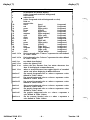
Add or replace the following manual entries in the
Reference Manual:"
New Entries
Revised Entries
gv.sh(l)
Xcvc(l )
Xgp(I)
Xv256(1)
Xvga( l )
"INTERACTIVE
Xl l
INTERACTIVE X11
Runtime System Guide
CONTENTS
Introduction to INTERACTIVE X l l
INTERACTIVE X l l Release Notes
Using the INTERACTIVE Easy Windows Environment
INTERACTIVE Motif Window Manager Release Notes
INTERACTIVE Motif Window Manager Installation Instructions
Character Bitmap Distribution Format
INTERACTIVE XII Installation Instructions and Maintenance
Procedures
INTERACTIVE XII Reference Manual
()
C)
Introduction to INTERACTIVE X11
,_...
Welcome to the INTERACTIVE Xll Runtime System Guide . This
guide contains the basic documentation you need to install, main
tain, and use INTERACTIVE X l l Version 2.0. Whether you are an
experienced programmer or a novice user, be sure to read the next
few pages of this document. They will tell you what is contained in
this guide and how to use it to your best advantage.
WHAT'S INCLUDED
The INTERACTWE XII Runtime System Guide includes:
•
INTERACfiVE XU Release Notes
Provides a description of the current release of INTERACTIVE
Xl l.
•
Using the INTERACfiVE Easy Windows Environment
Describes how to install the INTERACTIVE Easy Windows*
Environment.
•
INTERACfiVE Motif Window Manager Release Notes
Provides a description of the current release of the INTER
ACTIVE Motif* Window Manager subset.
•
INTERACfiVE Motif Window Manager Installation Instructions
Describes the basic requirements and procedures that are neces
sary to install the current release of the INTERACTIVE Motif
Window Manager subset.
•
Character Bitmap Distribution Format
Describes Adobe* System's character bitmap distribution format
(BDF). Information on the form of a font bitmap description file
is provided.
•
INTERACfiVE XU InstaUation Instructions and Maintenance
Procedures
Provides step-by-step instructions for installing INTERACTIVE
X l l and discusses the component packages of INTERACTIVE
X 1 1 . It describes how to perform the preliminary setup pro
cedures that are required to use the system once it is installed.
This document also discusses building new servers, removing
servers, making default servers, modifying configuration
2
Introduction to INTERACTIVE X1 1
-
Version 2.0
information, installing new X device drivers, and adding and
deleting X users. It includes information on running the server
and removing X packages from the system, and discusses the
kernel facilities required to run X.
•
INTERACTIVE Xll Reference Manual
Includes INTERACTIVE's proprietary server and driver manual
entries, as well as entries applicable to X l l , Release 4 client
programs.
•
Reader's Comment Form
Provides you with a way to tell us what you like or dislike about
this guide and to send us your ideas for making it even better.
Other documentation supplied with the INTERACTIVE X 1 1 Run
time System:
•
O'Reilly & Associates X Window System User's Guide, Motif
Edition
Describes window system concepts and features, including
display servers, client application programs, window managers,
and the x t e r m terminal emulator.
WHERE TO BEGIN
The INTERACTIVE Xll Runtime System Guide includes docu
ments for users at all levels of expertise. Depending on your experi
ence, you may want to use this guide in a number of different ways.
The following outline provides some suggested ways to use this
guide:
•
H you are a beginner
o
o
o
First, read this document to get to know what INTERACTIVE
X 1 1 is. Then, read section 1 of the X Window System User's
Guide , which is supplied as a supplement to this guide.
•
•
H you are an experienced
UNIX* System user
Read the "INTERACTIVE X l l Release Notes" for information
on INTERACTIVE X 1 1 Version 2.0. For more detailed and
technical information about the X Window System* , refer to the
X Window System User's Guide .
o
H you are installing and maintaining the system
o
o
o
o
o
Read and follow the steps outlined in "INTERACTIVE X 1 1
Installation Instructions and Maintenance Procedures."
�
Introduction to INTERACTIVE X11
•
- Version 2. 0
3
If you want the latest system information ...
Read the "INTERACTIVE X1 1 Release Notes" which will pro
vide you with up-to-the-minute information on Version 2.0 of
INTERACTIVE XII.
The documentation included in this guide provides information
about how to install, use, and maintain INTERACTIVE X 1 1 . This
guide is intended for users who will be running the INTERACTIVE
X 1 1 Runtime System.
If you plan to develop X applications, refer to the INTERACTIVE
XII Development System Guide . This guide is supplied with the
INTERACTIVE X 1 I Development System and includes:
•
Inter-Client Communication Conventions Manual
Provides conventions that allow clients to cooperate in the areas
of selections, cut buffers, window management, session manage
ment, and resources. This document is reprinted from the X
Consortium document of the same name.
•
fii"""
INTERACfiVE TCP /IP Programmer's Supplement
Presents supplemental information about how to program the
USL Transport Layer Interface ( also referred to as TLI or the
Transport Interface ) and the Berkeley Software Distribution
(BSD) socket interface.
Other documents supplied with the INTERACTIVE XI 1 Develop
ment System are the:
•
•
•
•
0'Reilly & Associates Xlib Programming Manual
Provides information about the X library, the C language pro
gramming interface of the X Window System. It includes a
conceptual introduction, tutorial material, and programming
examples.
O'Reilly & Associates Xlib Reference Manual
Contains the manual entries for the X library.
0' Reilly & Associates X Toolkit Intrinsics Programming
Manual, Motif Edition
Describes how to use the X Toolkit routines.
O'Reilly & Associates X Toolkit Intrinsics Reference Manual
Contains reference pages for the X Toolkit functions.
4
Introduction to INTERACTIVE X1 1 - Version 2. 0
OVERVIEW OF INTERACTIVE X11
INTERACTIVE X 1 1 is a network-based graphics system. It is based
on X 1 1 Release 4 of the X Window System that was developed at
MIT. X 1 1 has been adopted as the industry-standard windowing
system. INTERACTIVE X 1 1 follows a client-server model. In a
client-server model, the server manages the graphical output and the
user input. The clients are application programs that perform
specific tasks. Clients communicate with the server, accepting user
input and sending graphical output commands to it. This division
permits the clients and the display server to work together on the
same system or to be separated across a network.
INTERACTIVE X 1 1 features include:
•
Network-transparent access to the display
•
High-performance, high-level, device-independent graphics
•
Hierarchical, resizable, overlapping windows
INTERACTIVE X 1 1 is divided into two system packages: the Run
time System and the Development System.
RUNTIME SYSTEM
The INTERACTIVE X 1 1 Runtime System contains the software
necessary to execute X 1 1 applications on INTERACTIVE UNIX
System V /386 Release 3.2, and the documentation required by
users and system administrators.
Network Transparency
INTERACTIVE X 1 1 is a complete implementation of X 1 1 built on
the INTERACTIVE UNIX System. It uses STREAMS-based Inter
process Communication (IPC) mechanisms to support a networked
client-to-server link that operates across networks. INTERACTIVE
X1 1
uses INTERACTIVE TCP /IP (Transmission Control
Protocol/Internet Protocol ) to communicate with X clients and
servers on any machine in a network. INTERACTIVE X 1 1 can also
be installed on a system without networking software, in which case
it automatically uses a local link between clients and the X server.
�
Introduction to INTERACTIVE X11
-
5
Version 2.0
Peripheral Support
The supported graphical displays include:
•
A variety of EGAJVGA boards that are register-compatible with
IBM* EGA/VGA video controllers
•
256-color VGA boards
•
85 1 4/A Graphics Processor (and register-compatible) boards
•
The TIGA* 340 1 0/34020 server supports the following boards:
•
COMPAQ* AG 1 024
•
Desktop Computing AGA 1 024*
•
IMAgraph* Tl- 1 2 1 0 series
•
MegaScan FDP-6 120
•
•
Number Nine Computer Corporation* PEPPER*
PR0 1 024ISA* and PEPPER PR0 1280*
•
Renaissance Rendition* II
•
Spectre* SP200*
•
Texas Instruments TMS340 1 0 Software Development Board
Cornerstone Technology Incorporated* - supporting 150dpi
monitors, DualPage*, and SinglePage XL*
•
Hercules* monochrome graphics card
•
Moniterm 2 1 /9 1 Viking server
•
Pixelworks Clipper Graphics Series from Pixelworks, Inc.
•
Sigma Designs LaserView* Plus
•
Bell Technologies Workstation Graphics Engine (Blit Express)
The supported mice include:
•
•
•
LOGITECH* Three-Button Serial
MouseMan* Serial and Bus Mice
and
Bus
Mice,
and
Microsoft* Two-Button Serial and Bus Mice
MSC Technologies (formerly Mouse Systems Corporation)
OMNIMOUSE* , Serial, and Bus Mice
6
Introduction to INTERACTIVE X1 1
•
-
Version 2.0
Micro Channel* Architecture (PS/2* ) and COMPAQ on-board
mice and compatibles
The supported keyboards include:
•
1 0 1 -key IBM AT*-style keyboard
•
84-key IBM PC-style keyboard
Performance
For boards without hardware graphics-drawing capabilities, INTER
ACTIVE has optimized the MIT frame-buffer code to enhance per
formance. For higher-end displays, INTERACTIVE takes full
advantage of the hardware features provided in intelligent graphics
controllers. INTERACTIVE also works with controller manufactur
ers to assist them in tuning their microcode to optimize performance
when using XII.
DEVELOPMENT SYSTEM
The INTERACTIVE XII Development System consists of the
software and programmer's documentation necessary to create XII
applications. It is intended primarily for application developers and
sophisticated end users.
Berkeley Facilities
The INTERACTIVE X 1 1 Development System includes a Berkeley
4. 3 (4.3BSD) compatible socket library to permit easy porting of
existing Berkeley-based X applications.
FEATURES AND ENHANCEMENTS
INTERACTIVE XII contains many performance and functional
enhancements. Some of the features are:
•
•
•
Optimized input code
Local connections use STREAMS pipes, eliminating the need for
INTERACTIVE TCPJIP for local connections
Pseudo-color support - the user can set the color desired, where
applicable
�
Introduction to INTERACTIVE X11
•
�
•
•
7
Graphics enhancements include:
•
Multiple clipping rectangle support
•
Rectangles as a special type of polygon support
•
Line segment support
•
Odd-even and winding fill rule support
•
•
Version 2.0
Fonts can be downloaded to the board on displays that provide
this feature - downloading fonts increases performance
dramatically
•
•
-
X l l R4 integer arc code resulting in speedups of up to 1 000
times faster
X l l R4 integer-based wide line code
Shared X 1 i b, which reduces the sizes of the clients and permits
faster loading of clients
Text-based MS-DOS* (DOS) applications can be run using the
x p c t e rm client developed and supplied by INTERACTIVE
vp i x and X co-exist with all the supported mouse devices on
the EGA and VGA displays - for DOS graphics applications,
vp i x can be run on one virtual terminal and X on another vir
tual terminal, allowing the user to VT flip between them
8
Introduction to INTERACTIVE X1 1
-
Version 2.0
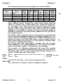
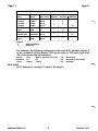
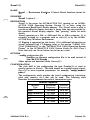
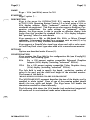
DOCUMENTATION REFERENCES
Throughout this guide, the following full documentation titles will
be referenced in shortened versions as follows:
Full Title
Shortened Version
INTERACTIVE UNIX System V /386
Release 3.2
Operating System Guide
Operating System Guide
INTERACTIVE UNIX System V /386
INTERACTIVE UNIX
Release 3.2
Guide for New Users
Guide for New Users
INTERACTIVE UNIX System V /386
Release 3.2
User's/System Administrator's
Reference Manual
INTERACTIVE UNIX System
User's f System Administrator's
Reference Manual
INTERACTIVE Software
INTERACTIVE SDS Guide and
Development System Guide and
Programmer's Reference Manual
Programmer's Reference Manual
INTERACTIVE UNIX
FOR MORE INFORMATION
INTERACTIVE X l l is a part of the INTERACTIVE Product Fam
ily, and it is supported by a complete set of documentation. For a
complete listing of all INTERACTIVE UNIX System-related docu
mentation, refer to the "Documentation Roadmap" in the INTER
ACTIVE UNIX Operating System Guide .
INTERACTIVE X11
Version 2.0.1
Release Notes
August 1992
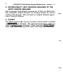
1. INTRODUCTION
INTERACTIVE Xll Version 2.0. 1 for the INTERACTIVE UNIX® Operat
ing System incorporates a number of improvements into the INTER
ACTIVE Xll product. These release notes supplement the Version 2.0
release notes and describe only the differences between Version 2.0 and
Version 2 .0. 1 .
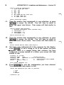
2. NEW FEATURES IN VERSION 2.0.1
There are several new features that are part of this release, including:
•
Support for the Super VGA Protected Mode Interface
•
Support for several new
•
A new version of xman
•
Enhancements to
(SVPMI)
VGA boards
xterrn and xpcterrn
These enhancements are described below.
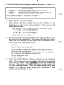
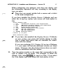
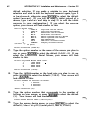
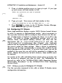
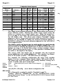
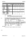
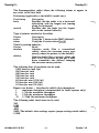
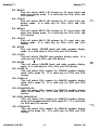
2.1 SVPMI Support
The Video Electronics Standards Association (VESA) has published a
document describing a text file format that can be used to illustrate the
characteristics of a Super
VGA board.
The capacity for interpreting such
a file has been included as part of INTERACTIVE
XII for the following:
-VGA
-v256
- gp
(85I4)
This makes it possible to support future Super VGA boards without
requiring another release of INTERACTIVE XII. A menu item (SVPMI)
has been added to the xconfig software. When selected, it displays all
of the video adapters supported through Super VGA prni files resident on
the system. These files have the format name.pmi and are located in
2
INTERAC TIVE X11 Release Notes- Version 2. 0. 1
/usr/lib/Xll/vesa/server,
where
servers listed above.
pmi
Third-party
server is one of the three
files must be installed in this
gv.sh(l).
directory. See also
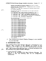
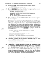
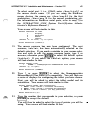
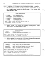
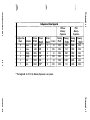
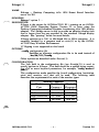
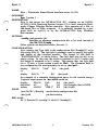
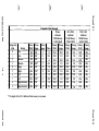
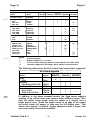
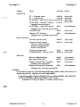
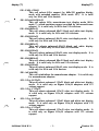
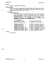
2.2 Support for New VGA Boards
With this release,
For the
pmi
files are supplied for the following boards:
VGA server:
ATI® VGA Wonder+
Genoa 6000 VGA
Genoa
7000
VGA
Orchid Prodesigner II VGA
Western Digital 90Cll VGA
Western Digital
90C30
VGA
For the v256 server:
ATI VGA Wonder+
COMPAQ® 486C
GenoaGVGA
Genoa 7000 VGA
Orchid Prodesigner II VGA
Western Digital WD90Cll VGA
Western Digital
WD90C30
VGA
For the 8514 server:
ATI
851 4A
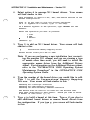
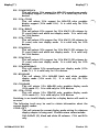
2.3 New Version of
xman
This release contains a new version of the
manual entries that are packed (extension
compressed (extension Z).
.
xman client that supports
z) as well as entries that are
.
2.4 Changes to
xterm/xpcterm
and xpcterm have been enhanced to support the programming
of keys with all modifiers, including
Use xmodmap to change
xterm
ICTRLI.
the meaning of a key. The same software change also causes the
key to work as expected.
ICAPS-LOCKI
INTERACTIVE X11
Version 2.0
Release Notes
,....
CONTENTS
1 . INTRODUCTION
0
0
0
0
2. DOCUMENTATION NOTES
0
0
0
0
3. NEW FEATURES IN VERSION 2.0
4. HARDWARE REQUIREMENTS
4. 1 Displays Supported
4.2 Mice Supported
4. 3 Digitizing Tablets Supported
4.4 Recommended Minimum Hardware
Configuration
0
0
0
0
0
0
0
0
0
0
0
0
0
0
0
0
0
0
0
0
0
0
0
0
0
0
0
0
0
0
0
0
0
0
0
o
0
0
0
0
0
0
0
0
0
0
0
0
0
0
0
0
0
0
0
0
0
6. CONTRIBUTED SOFTWARE
0
0
7. DEVELOPMENT SYSTEM
0
0
0
8. OPERATING SYSTEM
0
0
0
0
9. NETWORKING
0
0
0
0
1 0. VIRTUAL TERMINALS
o
0
0
0
0
1 1. X SERVER
0
0
0
0
0
0
0
0
0
12. CLIENTS
(""
0
0
0
0
0
0
0
0
0
0
0
0
1 3. MISCELLANEOUS
0
-i-
.
0
0
.
0
0
0
0
o
0
0
0
0
0
0
0
0
0
0
0
.
1
1
0
5. INSTALLING THE RELEASE
.
5. 1 Removing Previous Versions of INTERACTIVE
X1 1
5.2 Changes to the Runtime System Package
5. 3 Installing INTERACTIVE X 1 1 Version 2.0
5.4 Obsolete Files and Directories
0
0
0
0
!"""'
0
0
0
0
0
.
0
1
3
3
4
4
4
0
.
0
0
5
5
5
6
8
0
0
8
0
0
0
8
0
0
0
0
8
0
0
0
0
0
0
0
0
0
0
0
.
.
0
0
.
9
0
.
0
9
0
10
.
.
.
11
.
.
.
13
INTERACTIVE X11
Version 2.0
Release Notes
October 1991
1 . INTRODUCTION
INTERACTIVE X l l Version 2.0 for the INTERACTIVE UNIX*
Operating System is based on Version 1 1 , Release 4 of the X
Window System* from MIT. Version 2.0 is a complete release of
INTERACTIVE X 1 1 . It introduces a number of improvements,
including reduced memory usage and performance enhancements.
This document describes the new features, hardware requirements,
special installation considerations, and potential problems you may
encounter with this release. This version runs on the INTER
ACTIVE UNIX System Version 2.2 or later.
2. DOCUMENTATION NOTES
X 1 1 manual entries that are referenced in the text but not included
in this manual can be found in the O'Reilly & Associates X Win
dow System User's Guide, Motif Edition .
The following entries included in the O'Reilly & Associates X
Window System User's Guide are not applicable to INTERACTIVE
X11:
xcol ( l )
xmh ( l )
3. NEW FEATURES IN VERSION 2.0
The server-specific manual entries are those Section 1 entries in the
"INTERACTIVE X 1 1 Reference Manual" in which the entry names
begin with an uppercase X. Refer to these entries to see which
boards are supported and the specific resolutions that are supported
for each.
Additional functionality that is part of this release:
•
The Xvg a and Xv2 5 6 servers now support the Microlabs Ulti
mate VGA and VGA Solution.
2
INTERACTIVE X1 1 Release Notes - Version 2.0
•
•
•
•
The X g p server now supports boards from Adex and ATI*.
The Xvg a , X v 2 5 6 , and Xqp servers may be configured using
an external text file based on the proposed Video Electronics
Standards Association (VESA) Super VGA Protected Mode
Interface (SVPMI).
�
The Xcvc, X l vp, Xhrc, Xqp, Xvq a , and Xv 2 5 6 servers
have been significantly improved. They now support cursors and
fill patterns of arbitrary size and offer improved performance.
All servers now indicate the correct visual type based on their
capabilities. Grayscale and monochrome displays will no longer
be reported as color displays. In addition, servers supporting
dynamic ( changeable ) colormaps can simulate static colormaps.
This allows some applications to work better, because the server
will return the closest color available rather than give an error if
the colormap is full.
Refer to X( 1 ), Xcon.fig(5), and Xcolors(5) for more information
on these features.
•
•
Screen Blanking
On displays that don't support screen blanking in hardware, the
server will simulate blanking the display by drawing a black rectangle to blank the display and generating an exposure event to
redisplay the screen.
Several new clients have been added to this release including:
xd i tv i e w
xman
xf iq
xma i l
•
�
t r o f f previewing program
manual entry browser
drawing program ( in contributed subset )
windowing mail interface ( in contributed subset )
When used with an INTERACTIVE display server, xpc t e rm
now emits the correct scan codes regardless of the type of key
board used. Applications that take advantage of the scan code
mode of xpc t e r m, such as the VP j ix* Environment, will now
function correctly when used with non-U.S. keyboards. A
command-line option, - n o i se, is provided for use with display
servers that are not supplied with INTERACTVE Xll.
�
INTERACTIVE X1 1 Release Notes - Version 2.0
3
4. HARDWARE REQUIREMENTS
4.1
Displays Supported
The displays supported in this release are:
•
TIGA* 340 1 0/34020 boards:
•
COMPAQ* AG 1 024 (Xcpq a g )
•
Desktop Computing AGA 1 024 (Xdc a g a )
•
IMAgraph* TI 1 2 1 0 (X i g s p)
•
MegaScan FDP-6 1 20 (Xm s f dp) (supported in dual-headed
mode only)
•
Number Nine PEPPER* PR0 1 280* (Xnnp)
•
Number Nine PEPPER PR0 1 024ISA (Xnnp i )
•
Renaissance Rendition II (X r r e n 2 )
•
Spectre* SP200* ( X s p 2 0 0 )
•
Texas Instruments TMS340 1 0 Software Development Board
(Xt i s db)
•
Moniterm 2 1 /9 1 Viking board (Xv i k i ng )
•
256-color VGA boards (Xv 2 5 6 )
•
8 5 1 4/A Graphics Processor (and register-compatible) boards
(Xgp)
•
Bell Technologies Workstation Graphics Engine (Blit Express)
(Xwg e )
•
•
•
Cornerstone Technology Incorporated* boards ( Xcvc )
EGA and VGA. All boards that are register-compatible with the
IBM* EGAfVGA standards, including the SunRiver* Fiber Optic
Workstations, will run on the Xvga server. Many boards are
also supported in their high-resolution modes. Refer to Xvga(l)
and Xconfig( 5 ) for a list of the boards and the board resolutions
that are currently supported.
Hercules* monochrome graphics card and compatibles (Xhrc)
4
INTERACTIVE X1 1 Release Notes - Version 2. 0
•
•
Sigma Designs LaserView* Plus ( X l vp}
Pixelworks Clipper Graphics Series from Pixelworks, Inc. This
includes the Clipper, the Micro Clipper, and the Ultra Clipper
( Xpw).
4.2 Mice Supported
,_,
.....
The mice supported in this release are:
•
•
•
•
LOGITECH* : three-button keyboard, serial, and bus mice; two
button keyboard and serial mice; MouseMan* serial and bus
mice.
Microsoft* : two-button keyboard, serial, and bus mice.
MSC Technologies, Inc. : OMNIMOUSE*; three-button optical
serial and bus mice; two-button optical serial and bus mice.
PS/2* on-board mouse and compatibles (including the COMPAQ
built-in mouse).
Xconfig(S) provides additional information on configuring mice.
If you need to temporarily run X 1 1 without a mouse, you can use
the nu l l m ou s e option for the mouse. However, no pointer
specific functions will be available under this configuration.
4.3 Digitizing Tablets Supported
INTERACTIVE X 1 1 Version 2.0 supports the following tablets and
compatibles:
•
•
Summagraphics* SummaSketch* Plus, models MM96 1 and
MM1201.
Kurta* IS/ONE* tablets in MM96 1 / 1 20 1 mode (switches C5 up,
C6 down, C7 down, and C8 up).
Xconfig(S) provides additional information on tablets.
4.4 Recommended Minimum Hardware Configuration
The recommended minimum hardware configuration is:
•
A minimum of 4 megabytes (MB) of real memory is required (6
MB are recommended). If you are running more than one
server, an additional 2 MB per server is recommended.
�
INTERACTIVE X1 1 Release Notes - Version 2.0
•
•
5
A minimum of 12MB of page ( swap ) space on your fixed disk is
recommended. If you . are running more than one server, an
additional 5MB per server is recommended.
You will need 10 to 12 MB of disk space on the I u s r file sys
tem to load the Runtime System package. To load the entire
system ( Runtime System, Contributed Software, Development
System, and Server Kit ) , you will need 20 to 22 MB of disk
space on the I u s r file system.
5. INSTALLING THE RELEASE
INTERACTIVE X l l Version 2.0 will install on the INTERACTIVE
UNIX Operating System Version 2.2 or later. You can overlay
INTERACTIVE X l l Version 2.0 on a previous release of X l l if one
is currently installed.
You should not be in the X11 environment at the time you install
( overlay ) Version 2.0, because this will cause certain files that must
be updated to be inaccessible.
5 . 1 Removing Previous Versions of INTERACTIVE X1 1
It is recommended that you do not remove the previous release, but
overlay Version 2.0 on top instead. If you need to remove the previ
ous release of INTERACTIVE X11, do not remove the System sub
package of the Runtime System. Removing this package may cause
you to have to reinstall parts of your system. In lieu of removing
the package, you can disable the kernel drivers that you no longer
need using the C ONFI GURE K E RN E L option in kcon f i g or the
x d r i v e rmgmt option of s y s a dm.
5.2 Changes to the Runtime System Package
•
In Version 2.0, the System and Servers subset contains only the
16 and 256 color VGA servers. Additional serv.ers are contained
in separate subsets. The installation and configuration pro
cedures for the servers have been substantially revised. Refer to
the "INTERACTIVE X11 Installation Instructions and Mainte
nance Procedures" for additional information.
•
The color database has changed in X11 Release 4. This may
result in slightly different colors appearing on screen than in pre
vious releases. It also has caused the default behavior of Motif*
to change, resulting in a different appearance of inactive window
borders.
6
INTERACTIVE X1 1 Release Notes - Version 2. 0
5 .3 Installing INTERACTIVE X1 1 Version 2.0
You should refer to the "INTERACTIVE Xll Installation Instruc
tions and Maintenance Procedures" for instructions on installing
this release. In addition, the following information should be noted.
•
•
�
To install INTERACTIVE Xll Version 2.0, you will need at
least 0.5 MB of free space in the /tmp file system (or in the
r o o t ( / ) file system, if / tmp is not a separate file system).
This is over and above the requirements specified in section 3,
"HARDWARE REQUIREMENTS ."
When installing the INTERACTIVE Xll Version 2.0 Runtime
System, any existing copies ofINTERACTIVE Xll input drivers,
INTERACTIVE Xll display drivers, fonts (miscellaneous, 75dpi,
and lOOdpi), microcodes, and Xll-specific kernel drivers will be
deleted. You should save any modifications or additions, partic
ularly those made in the font directories, before installation.
•
When installing the INTERACTIVE Xll Version 2.0 Develop
ment System, any existing copies of Xll i nc l ud e files and
libraries will be deleted. You should make copies of any thirdparty
i nc l ud e
files
installed
in
the
directory
/ u s r / i nc l u d e / X 1 1 .
•
•
The following files will be updated when you install INTER
ACTIVE Xll Version 2.0 on top of a previous release ofINTER
ACTIVE Xll. If you have made changes to any of these files,
you should save the modified files before installing INTER
ACTIVE Xll Version 2.0:
•
/ u s r / l i b / X 1 1 / Xcon f i q
•
/ e tc / X ? . h o s t s
•
/ u s r / l i b / X 1 1 / a pp - d e f a u l t s /*
•
/ u s r / l i b / X 1 1 /< r e s ourc e f i l e s>
•
/ u s r / l i b / X 1 1 / f ont s /*
•
/ u s r / l i b / X 1 1 /xdm/*
•
/ u s r / i nc l ud e / X 1 1 /*
•
X libraries in / u s r / l i b
The
format
of
the
/ u s r / l i b / X 1 1 /Xcon f i q
entries
in
the
file
has changed for the Xvga,
l
INTERACTIVE X1 1 Release Notes - Version 2.0
Xv256, and Xgp servers.
7
This change is reflected in the
s y s a dm menus. It is recommended that you look at the sample
entries provided or run the xmgmt option of s y s a dm to
configure your system after installation.
•
•
•
•
If you had any fonts previously installed in the system, copy
them into the appropriate directories after completing the instal
lation and run mk f ontd i r in each of those font directories.
Refer to mkfontdir( 1 ) for more information.
The program I u s r /b i n /X 1 1 IX is now linked to the client
/ u s r / b i n /X 1 1 / x f r ont as part of the installation. You
should not link I u s r /b i n/X 1 1 /X to a specific server. The
correct server will be executed based on the server configuration
information and command line arguments used. Refer to
xfront(l) for more information.
In order to configure and build a server and turn on the associ
ated driver, you must run the xmgmt option of s y s a dm. The
system will ask you if you want to use this option following the
installation of the INTERACTIVE X 1 1 System and Servers sub
set as well as following the installation of any additional servers.
Due to hardware considerations, in certain cases, the
configuration information you choose for a mouse might not be
related to the actual brand name of the mouse you have. For
examples and additional information, refer to the "INTER
ACTIVE X 1 1 Installation Instructions and Maintenance Pro
cedures" and to Xconfig(5).
In order to support the mouse supplied with the ATI VGA
Wonder* board, configure it as a LOGITECH two-button bus
mouse. The ATI VGA mouse is not a Microsoft mouse as the
documentation supplied byATI states.
•
The kernel tunables NQU EU E and N S TREAM are updated as
part of the installation of the System and Servers subset in the
INTERACTIVE Xll Runtime System package. However, it
may be necessary for you to increase the settings of these vari
ables if you run out of "STREAMS resources." To do this,
increase the settings in the file / e tc /con f /c f . d/mtune
and then build a kernel.
If you are installing only the Clients subset (and not installing
the System and Servers subset), then you must update the tun
abies manually and build a kernel.
8
INTERACTIVE X1 1 Release Notes - Version 2.0
5.4 Obsolete Files and Directories
The following files and directories, supplied in Releases 1.0 and 1. 1
of INTERACTIVE X 1 1 , are now obsolete and will be removed
automatically if you are updating to X 1 1 Version 2.0:
•
/ u s r / 1 i b / X 1 1 / X s e rve r s /mou s e
•
/ u s r / 1 i b / X 1 1 / X s e rv e r s / k e ybo a r d
•
/ u s r / op t i on s / x 1 . name
•
/ u s r / o p t i on s / x 2 . name
•
/ u s r / o p t i o n s / x r . name
6 . CONTRI BUTED SOFTWARE
The Contributed Software is provided on an "as-is" basis. This
software is unsupported, and it may not run on all configurations.
7. DEVELOPMENT SYSTEM
A new library, 1 i bXma 1 1 oc, which is substantially faster than
the standard m a 1 1 oc, r e al 1 oc, and f r e e functions available
in 1 i bc and 1 i bma 1 1 oc, has been provided.
Prior releases ofINTERACTIVE X 1 1 required client programs to be
linked with the i n e t library. X 1 1 Version 2.0 does not have this
requirement, however, programs must now be linked with the
n s 1 s library. This will occur automatically when using a
maki./ile generated from an Imake.file. To manually include this
library, add - 1 n s 1 s to the end of the final link line of the pro
gram. The Runtime version of n s 1 s will be installed as part of
the core base system. The library for compilation ( 1 i b n s 1 - s . a )
is in theSTREAMS Facilities subset.
8. OPERATING SYSTEM
You may have to consider the following operating system related
issues when installing and runningINTERACTIVE X 1 1 :
•
The keyboard mouse (COMPAQ built-in mouse ) driver, the
Microsoft bus mouse driver, and the LOGITECH bus mouse
driver are in the Additional Drivers subset. If you are using one
of these mice, install the appropriate driver from the Additional
Drivers subset before you install X 1 1.
�
INTERACTIVE X1 1 Release Notes - Version 2.0
•
9
If you are installing INTERACTIVE Xll on the INTERACTIVE
UNIX System Version 2.2 or 2.2.1 and you have more than 100
drivers installed, your system can malfunction. To prevent this,
install the Kernel Configuration Update ssu . 8. This step will
not be necessary for most users.
9. NETWORKING
The following information applies to networking:
•
If you have not installed INTERACTIVE TCP fiP (Transmission
Control Protocol/Internet Protocol) on your system, you will get
the message:
NOTE :
TCP
conne c t i on s
are not ava i l a b l e .
This message states that you cannot have clients that access X
across the network. X is completely functional for local connec
tions. You will get this message ifTCP/IP is not installed or if
you are running init at level 2 (see init(lM) in the INTER
ACTIVE UNIX
System User's/System Administrator's Reference
Manual).
•
This version of INTERACTIVE Xll requires INTERACTIVE
TCP/IP to run TCP connections across the network. There are
no such limitations for local connections.
•
If you installed the INTERACTIVE TCP/IP extension after
INTERACTIVE Xll, you must reinstall INTERACTIVE TCP/IP
after removing the INTERACTIVE Xll Runtime or Develop
ment systems.
•
If you are running the name server on a slow machine, it may
take a long time to resolve names in the / e tc /X 0 . h o s t s file
if you have several entries. This can cause x i n i t to time out
before it can connect to a server.
10. VIRTUAL TERMINALS
The following information applies to virtual terminals:
•
Currently, the server uses a new VT every time you run X.
Hence, every X server needs a free VT that does not have an
active g e t t y on it. To change the number of active VTs on
your system, select the v i r t t e rm option of the TTY
MANAGEMENT (sys a dm t tymgmt ) menu.
10
•
•
INTERACTIVE X1 1 Release Notes - Version 2.0
The server for Pixelworks displays, does not implement VT
flipping in single-headed mode.
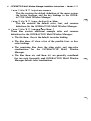
The following information pertains to VT flipping on boards supported by the TIGA 340 1 0f34020 server.
VT flipping is supported on the following boards:
•
COMPAQ AG 1 024 (Xcpq a g}
•
Number Nine PEPPER PR0 1 024ISA (Xnnp i )
•
Renaissance Rendition II (X r r e n 2}
•
Spectre SP200 (X s p 2 0 0 )
•
�
Texas Instruments TMS340 1 0 Software Development Board
(Xt i s db)
V T flipping i s not supported on the following boards:
•
Desktop Computing AGA 1 024 (Xdc a g a}
•
IMAgraph TI 1 2 1 0 (X i g s p )
•
•
•
MegaScan FDP-6 1 20 {Xm s f dp) (supported i n dual-headed
mode only)
�
1
Number Nine PEPPER PR0 1 280 {Xnnp)
When using INTERACTIVE X 1 1 and the VPfix Environment
(on the console or on another VT) together and sharing a serial
mouse, make sure you use the COM 1 MOU S E setting for the
serial mouse in your VPfix configuration file. If you use the
C OM 1 setting, VPfix does not close the mouse device, and the X
server cannot access the mouse device when you VT flip to X.
1 1 . X SERVER
The following information applies to the X server:
• At start-up, the X server may complain that the LOGITECH
serial mouse is not responding. This may also happen during VT
flipping. The code in INTERACTIVE X 1 1 that allows the mouse
to coexist with VPfix attempts to query the mouse for its current
parameters and may become out of sync when the mouse is
moved at start-up or VT flip time. The workaround is to not
move the mouse during these times.
.�
INTERACTIVE X1 1 Release Notes - Version 2.0
•
•
11
Since lNUM-LOCKI and l CAPS-LOCKI are modifier keys, they
affect the mouse buttons if either is on. You must configure
your window manager to invoke the same functions regardless of
whether INUM-LOCKI or l CAPS-LOCKI are on or not.
Panning may not work on all TIGA servers depending upon your
hardware environment. Refer to the following Runtime System
manual entries for specific references to panning support for
. your board:
Xcpqag(l}
Xdcaga(l}
Xigsp(l}
Xmsfdp(l)
Xnnp(l}
Xnnpi(l}
Xrren2(1}
Xsp200(1)
Xtisdb(l)
•
The Cornerstone ( Xeve) server in its default configuration may
not recognize some of the newer board models. If server failure
occurs and the console displays an error message such as
Unknown eve b o a r d type; mu s t s p ec i f y r e s o l u
t i on, you must add the appropriate parameters to fields in the
Xc o n f i g file ( see Xcvc(l) for information ).
•
Downloading a big bitmap may take a great deal of time on
some servers, and the cursor freezes during the process. This
time period can be up to 3 or 4 minutes, giving the illusion that
the server has stopped operating.
1 2. CLIENTS
The I u s r I 1 i b l X 1 1 directory contains some X client resource
default and example files:
•
•
The a pp - d e f a u l t s directory contains files for applications
that require only a single file for default settings.
Applications with more than one file, such as xdm(l), xinit(l) ,
and uwm( 1) , require individual client directories.
12
INTERACTIVE X1 1 Release Notes - Version 2.0
The following information applies to specific client application
programs:
•
x pc t e r m
•
•
•
•
xpc t e rm also emulates the AT keyboard. Programs that
perform better when using an AT-style keyboard should be
run under xpc t e rm rather than x t e r m. Further, when
running vp i x in an xpct e rm window, the T E RM shell
variable should be set to xpc t e rm for it to function
correctly. This should be the default TERM variable setting
under xpc t e rm.
VP f ix Version 1. 1. 1 cannot handle the SIGWINCH signal
that is sent when a window is resized. This has been
corrected in VP f ix Version 1.2.0. If you are still running
VP f ix Version 1 . 1. 1 , beginning with release 1 . 3 of INTER
ACTIVE XII, xpct e rm provides the option of not sending
the SIGWINCH signal to a process such as VP f ix. Refer to
the information on the menu items accessible via the second
button menu ( accessed via ICTRLI second button ).
xpr
•
•
Note that the AT* terminal character set has special charac
ter glyphs in the range 0 through 3 1 and 1 27 through 255.
Only the e g a and vga fonts supplied with INTERACTIVE
X 1 1 support these special character glyphs. Programs that
use these special character glyphs, such as those in the
TEN /PLUS* Environment and the VP fix Environment,
should be run from an xpct e rm window that uses one of
these fonts. Programs that do not need these special charac
ter glyphs can be run using any other font.
When using xpr with the HP* LaserJet*, the printer must
have at least 1 . 5 MB of memory in order to process a full
page image.
x t e rm
•
The x t e rm program emulates a v s 1 0 0 (VT 1 02*-style ) terminal. Set your TERM variable to xt e rm or v s 1 0 0 if you
have a 66-line xt e rm window. Set your T ERM variable to
x t e rm s , v s 1 0 0 s , or vt 1 0 0 if you have a 24-line
x t e rm window.
�
1
13
INTERACTIVE X1 1 Release Notes - Version 2.0
•
fli"""
•
Any unrecognized escape sequence will cause x t e r m to not
process input or output until a s o f t r e s e t is done via the
xt e rm menu.
x dm
•
If you are running xdm to an X terminal that does not sup
port the XDMCP protocol, you will notice the sessions on the
X terminal being terminated after a short period of time.
This happens because xdm pings the X terminal, and the X
terminal does not respond. To prevent this from occuring,
add one of the following lines to the appropriate xdm
configuration
file
(the
default
file
is
/u s r/ l i b/X 1 1 /xdm/xdm -eon f i q �
D i s p l ayManag e r . HOS T_S ERVER . p i ngin t e r va l :
0
or:
D i s p l ayMan a g e r•p i ngint e rva l :
0
where H O S T is the host name of the X terminal, and
S E RV E R is the server number, usually 0 .
Some client programs that ran successfully in previous releases of X
may terminate unexpectedly when used with X 2.0. This may be
avoided by starting the server with the - be option or by running
x s e t be.
13. MISCELLANEOUS
Messages that start with the word WARN ING are messages that
give you information. If you receive a WARN IN G message, it does
not mean that something is wrong with your system.
If your EGA or VGA display adapter has auto-switching, turn it off.
The auto-switching feature tries to determine the type of adapter
the software is expecting. Some manufacturers call this the VGA
Implementation Type.
In UNIX System V /386 Release 3.2, the po l l system call is only
capable of polling on STREAMS devices. INTERACTIVE has
enhanced the operating system so that it supports polling on pipes
and terminal (tty) devices. Application developers can use the
s p i p e library call to set up a STREAMS pipe connection.
I
::·
,._
•
Using the INTERACTIVE
Easy Windows Environment
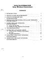
CONTENTS
l. INTRODUCTION
1
2. INSTALLATION REQUIREMENTS
2
3. KNOWN PROBLEMS AND
WORKAROUNDS
4
.
.
.
•
.
.
4. INSTALLING THE INTERACTIVE EASY WINDOWS
ENVIRONMENT
.
•
.
•
•
.
•
•
.
.
5. USING THE EASY WINDOWS
ENVIRONMENT
5. 1 Using the Icon Box
5.2 Exiting the Easy Windows Environment
•
.
6. TROUBLESHOOTING
.
•
.
•
•
•
.
.
•
•
.
•
.
.
.
.
•
•
.
.
.
.
.
.
.
.
.
.
.
.
.
.
.
.
.
.
•
11
11
11
12
13
13
14
.
.
.
.
.
.
.
.
.
.
•
•
•
•
•
•
.
.
.
•
•
•
14
•
•
•
15
•
•
.
.
.
9. REMOVING THE EASY WINDOWS
ENVIRONMENT
•
.
•
8. UPDATING YOUR EASY WINDOWS
ENVIRONMENT
•
•
•
7. NOTES FOR ADVANCED USERS
7. 1 What the Easy Windows Environment
Provides .
7.2 Stopping Installation
.
5
.
.
.
-i-
.
•
•
Using the INTERACTIVE
Easy Windows* Environment
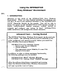
1 . INTRODUCTION
Welcome to the world of the INTERACTIVE Easy Windows
Environment. When you have finished installing this package, you
will have an easy-to-use graphical interface to the INTERACTIVE
UNIX* Operating System on the console. You will be able to
access the power of the INTERACTIVE UNIX System through a
simple, understandable desktop manager, without having to
integrate and configure your system by hand. INTERACTIVE
makes installation and configuration almost automatic.
Advanced Users - Getting Started
The INTERACTIVE Easy Windows Environment can be used only
on the console. The following software must be installed in this
order, configured, and running correctly, before you install the
Easy Windows Environment diskette:
INTERACTIVE X 1 1 Runtime System
- System and Servers diskettes
- Clients diskettes
- The appropriate server diskette, if a non-VGA
display is to be used
In addition, in order to obtain maximum functionality,
the following packages may be installed:
INTERACTIVE Motif* Window Manager
INTERACTIVE Looking Glass* Desktop Manager
After the software listed above is installed and running,
insert the diskette labelled Easy Windows Environment
and type s y s a dm i n s t a l lpkg.
2
Using the INTERACTIVE Easy Windows Environment - Version 2.0
2. INSTALLATION REQUIREMENTS
The INTERACTIVE Easy Windows Environment can be used only
on the console. To install and run the INTERACTIVE Easy Win
dows Environment, you must first install the following software on
your system, in this order:
•
INTERACTIVE X 1 1 Runtime System
System and Servers diskettes
Clients diskettes
The appropriate server diskette, if a non-VGA display
is to be used
In addition, the following packages may be installed at any point to
obtain full functionality:
•
INTERACTIVE Motif Window Manager
•
INTERACTIVE Looking Glass Desktop Manager
IIF
These packages must be configured and running correctly to
successfully install and use the INTERACTIVE Easy Windows
Environment.
You will use the same s y s a dm i n s t a l l pkq command that
used to install other INTERACTIVE software.
•
To
is
·�
install the
INTERACTIVE X 1 1 Runtime System, read the
"INTERACTIVE X 1 1 Installation Instructions and Maintenance
Procedures" in this guide. If you are installing the INTER
ACTIVE X 1 1 Runtime System on your machine for the first
time, build a new kernel when prompted, but do not reboot the
machine at that time. You will reboot at a later time in the
Easy Windows Environment installation.
•
To install the
INTERACTIVE Motif Window Manager, read the
"INTERACTIVE Motif Window Manager Release Notes" and
the "INTERACTIVE Motif Window Manager Installation
Instructions" in this guide.
•
To install the INTERACTIVE Looking Glass Desktop Manager,
read the INTERACTWE Looking Glass Professional Release
Notes.
�
\.
Using the INTERACTIVE Easy Windows Environment - Version 2.0
,.....
3
,.. Note that if you have previously installed and configured any of
these software packages and you install the INTERACTIVE
Easy Windows Environment, the system will ask if it should
overwrite the configuration files in / u s r / l i b / X 1 1 / xdm.
You may want to back up or change the name of any of these
configuration files you want to save.
4
Using the INTERACTIVE Easy Windows Environment - Version
2.0
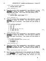
3. KNOWN PROBLEMS AND WORKAROUNDS
For users with 1 6 color X Windows Servers, the combination of
running Looking Glass and Motif requests more colors for their use
than the 1 6 colors that are available. As a result, the first client
appears in full color (if used with Easy Windows this is the Motif
Window Manager), and the next client (Looking Glass) appears in
monochrome. Two workarounds exist:
•
•
Reconfigure mwm to use fewer colors (typically by using the
sample Mwm configuration files provided in the MWM subset).
Upgrade the display subsystem to one with greater color capa
city (in this case, to a 256 color adapter).
Using the INTERACTIVE Easy Windows Environment - Version
2.0
5
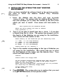
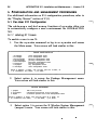
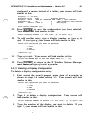
4. INSTALLING THE INTERACTIVE EASY WINDOWS
ENVIRONMENT
After you have installed the software listed in the previous section,
you need to install the diskette labelled Easy Windows
Environment .
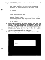
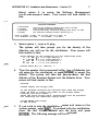
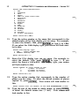
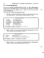
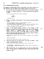
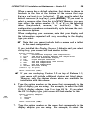
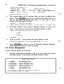
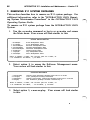
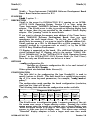
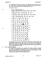
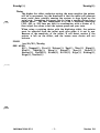
1. Insert the diskette into the drive and type s y s adm
i n s t a l l pkg. On systems with two diskette drives, the sys
tem then prompts you to enter the number of the drive from
which you want to install. Your screen will look similar to
this:
Th i s
system h a s two d i s k e t t e dr i ve s .
E n t e r the d r i v e numb e r you w i s h to
f r om ( ( d e f a u l t ) 0 , 1 ) :
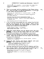
2.
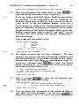
Type 0 if you plan to install from the A : drive, 1 if you plan
to install from the B : drive. The system then prompts you for
the density of the diskettes you are using for the installation.
Your screen will look similar to this:
Ent e r d e n s i ty of
the d i sk e t t e s you a r e
1
2
3
4
" h i gh d e n s i ty )
" h i gh d e n s i ty )
" low d e n s i ty )
" l ow d e n s i ty )
I
)
)
)
1 . 2MB
1 . 4 4MB
3 6 0 1C B
7 2 0 1CB
Please
3.
i n s ta l l
(5
(3
(5
(3
1 /4
1/2
1 /4
1/2
enter # ( 1 - 4 ) ,
default
i n s t a l l i ng f r om :
1 :
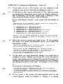
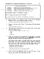
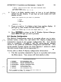
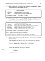
Type in the number corresponding to the type of diskettes you
are using for the installation. The system asks you to insert
the first diskette of the subset into the diskette drive. Your
screen will look similar to this:
Conf i rm
Please
i n s e r t the
f l oppy d i s k .
I f the program i n s t a l l a t i on r e qu i r e s m o r e than one f l oppy
d i s k , b e sure t o i n s e r t the d i s k s in the p r o p e r o r d e r ,
s t a r t i ng w i th d i s k numb e r 1 .
A f t e r the f i r s t f l oppy d i s k , i n s t r u c t i on s w i l l b e p r ov i d e d
f o r i n s e r t i ng t h e rema i n i ng f l oppy d i s k s .
S t r i k e ENTER when r e ady
o r ESC t o s t op
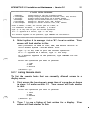
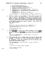
4.
Press I ENTER I . The system asks you to confirm that you want
to begin the installation of that specific subset:
6
Using the INTERACTIVE Easy Windows Environment - Version
2.0
I n s t a l l a t i on i s i n progr e s s -- do not r emove the f l oppy d i s k .
I n s t a l l I N T ERAC T I V E E a s y W i ndows Env i r onment V e r s i on 2 . 0 ? ( y ) :
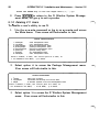
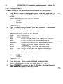
5.
Press I ENTER I to start the installation process. The system
displays the subset file names that are being loaded onto your
machine. Your screen will look similar to this:
I n s t a l l i n g I NTERAC T I V E E a s y W i ndows Env i ronment V e r s i on 2 . 0 .
C o pyr i ght ( c ) 1 9 9 0 - 1 9 9 1 Int e r a c t i ve S y s t e m s Corp
A l l R i gh t s R e s erved
The f o l l o w i ng f i l e s are be i ng i n s t a l l e d :
7 6 2 b l o cks
I n o r d e r to c onf i gu r e t h e E a s y W i ndows Env i r onment ,
you w i l l n e e d to run the c ommand ' s ys adm e a s y s e tup ' .
Do you want to do that now? [ y , n ]
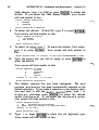
6.
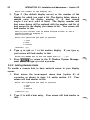
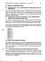
Type y and press I ENTER I . Your screen will look similar to
this:
Runn i ng Sys adm . . .
Runn i ng s u b c ommand ' e a s y s e tup ' f r om menu
EASY W I NDOWS ENVI RONMENT MANAGEMENT MENU
' e a s yw i ndowmgmt ' ,
Th i s s c r i pt w i l l a l low you to enab l e or d i s a b l e automat i c
s t a r tup o f I NTERACTIVE E a s y W i ndows s e s s i on s f o r the
c on s o l e d e v i c e .
Ava i l a b l e o p e r a t i ons a r e :
a ) add entr i e s for automat i c s t artup o f
E a s y W i ndows s e s s i o n s
d ) d e l e t e entr i e s for automat i c s e s s i on s t a rtup
q ) qu i t
e n t e r s e l e c t i on :
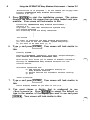
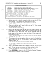
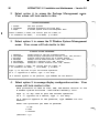
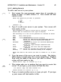
7.
Type a and press I ENTER I . Your screen will look similar to
this:
Wh i c h d i s p l ay numbe r do y o u w a n t to u s e
8.
[0]?
You must choose a display that is configured to use
/ d e v/con s o l e . Press IENTERI to accept the default or
type in the number of the display you want to use and press
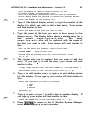
I ENTER I . Your screen will look similar to this:
Using the INTERACTIVE Easy Windows Environment - Version
2.0
7
I n i t t a b h a s b e e n updat e d .
E a s y W i ndows s e s s i on s on the c on s o l e have b e e n e n a b l e d .
You s h o u l d now r e boot the s y s t e m f o r the change to take
effect .
I n s t a l l a t i on of
i s comp l e t e .
E a s y W i ndows Env i r onment
- V e r s i on 2 . 0
C on f i rm
Please
i n s e r t the
f l oppy d i s k .
I f the program i n s t a l l a t i on r e qu i r e s mor e than one f l oppy
d i s k , b e s u r e to i n s e r t the d i s k s in the p r o p e r o r d e r ,
s t a r t i ng w i th d i s k numbe r 1 .
A f t e r the f i r s t f l oppy d i s k , i n s tru c t i ons w i l l b e prov i d e d
f o r i n s e r t i ng t h e r ema i n ing f l oppy d i s k s .
S t r i ke ENTER whe n r e ady
o r E S C to s t op .
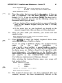
9.
Press I ESC I to return to the system prompt. You must now
use the s hu t d own command to shut down and reboot your
machine. ( For information about s hutdown, refer to sec
tion 3, "SHUTTING DOWN AND BRINGING UP THE SYS
TEM" in the "System Administration for New Users of the
INTERACTIVE UNIX Operating System" in the INTER
ACTIVE UNIX System Guide
1 0.
for New Users.
When you log in again, your screen will look similar to this:
8
1 1.
Using the INTERACTIVE Easy Windows Environment - Version
Log in as usual. (If you need to abort the Easy Windows
Environment installation for some reason, you can press l ESCl
at this point to do so. ) Your screen will look similar to this:
S t a r t i ng xdm i n 30 s e conds .
c o n s o l e g e tty or p r e s s x to
1 2.
2.0
Pr e s s E S C to abort to a
s t a r t xdm i mm e d i a t e l y .
Type x to start the Easy Windows Environment right away.
Your screen will look similar to this:
Th i s i s the f i r s t t i me you have l o g g e d i n und e r the
I NTERAC T IVE Easy W i ndows Env i r onment .
You now have
the opt i on o f i n s t a l l ing the Easy W i ndows
c o n f i gurat i on f i l e s i nto your home d i r e c tory , wh i c h
w i l l automa t e s t artup every t i me you l o g i nto t h e
E a s y W i ndows Env i ronment .
( R e m e m b e r to move the c u r s o r
your answer s . )
Do you want to cont i nue
1 3.
i nto the w i ndow b e f o r e typ i n g
[y] ?
Put the cursor in the window and press l ENTERl to continue.
If you want to stop the installation for some reason, type n
(meaning "no"), press I ENTER I , and skip to section 6.2,
"Stopping Installation." If you choose to continue, your
screen will look similar to this:
Th i s p r o c e du r e w i l l a l l ow you to i n s t a l l the s t andard E a s y
W i ndows c o n f i gurat i on f i l e s .
For e a c h f i l e , i f you a l r e a d y
have a f i l e o f the s ame name , y o u w i l l b e a s k e d i f y o u want
t o r e p l a c e it w i th the Easy W i ndows v e r s i on o f the f i l e .
I f you choo s e to do s o , the procedure w i l l s av e your o l d
f i l e w i th the e x t e n s i on " . o l d " append e d to i t .
I f it
c annot d o t h i s , i t w i l l w a r n you a n d a l low y o u ove rwr i t e
o r s k i p the f i l e .
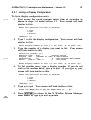
I n s t a l l the X r e s o u r c e s f i l e
1 4.
( . Xd e f a u l t s )
If you are unfamiliar with these confi tration files, you should
accept the default and press lENTER to install the file. The
system confirms your choice for each file and displays the
location where it is being installed. For example:
I n s t a l l e d the X r e sour c e s f i l e as
1 5.
f
[y] ?
/ u s r / j ane / . Xd e f a u l t s
You are asked about each of the following configuration files
in turn. Press l ENTERI each time you want to install the new
file; type n (meaning "no") and press lENTERI each time you
do not want the new file to be installed.
�
'
Using the INTERACTIVE Easy Windows Environment - Version
I n s t a l l the Mot i f W i ndow Mana g e r
( . mwmr c ) [ y ] ?
Instal l
the xdm X s e s s i on f i l e
you want to i n s t a l l
y o u r d i s p l ay [ y ] ?
the
Do
you want
i c on box
Ins t a l l
the
to have an
MWM l o w - r e s
Do you want to i n s t a l l
y o u r d i s p l ay [ y ] ?
conf i gu r a t i on f i l e
( . x s e s s i on )
Do
[y] ?
s t andard MWM r e s ou r c e
file
for
[n] ?
c o l o r r e s ou r c e
the
9
2.0
f i le
( Mwm )
s t andard Look i ng G l a s s
[y] ?
f i les
for
After you press I ENTERI to accept the default, your screen
will look similar to this:
I n s t a l l e d the Look i ng G l a s s
/ u s r / j an e / l g / l g conf i g
I n s t a l l e d t h e L o o k i ng G l a s s
/ u s r / j an e / l g / l g p r e f
I n s t a l l e d t h e Looking G l a s s
/u s r / j an e / l g / l g d e sktop
I n s t a l l e d the Looking G l a s s
/ u s r / j an e / l g / l g c o l o r s
I n s t a l l e d the L o o k i ng G l a s s
/ u s r / j an e / l g / l g _ d i rh i s t
conf i gur a t i on f i l e
as
user preferences f i l e as
D e s ktor·
color
f i l e as
c ho i c e s
f i le
as
d i r e c to r y h i s t o r y f i l e a s
The system then lists the files it has added or changed during
the installation. Your screen will look similar to this:
The f o l l ow i ng f i l e s have b e e n i n s t a l l e d or upd a t e d f o r the
INT ERAC T IVE Easy W i ndows Envi ronment :
/ u s r / j ane / . Xde f a u l t s
/ u s r / j an e / . mwmr c
/ u s r / j an e / . x s e s s i on
/ us r / j ane /Mwm
/u s r / j an e / l g / l g conf i g
/ u s r / j an e / l g / l g - p r e f
/ u s r / j an e / l g / l g - d e s ktop
/u s r / j an e / l g / l g - c o l o r s
/ u s r / j an e / l g / l g = d i rh i s t
Press
1 6.
[ ENTER ]
t o s t a r t your E a s y W i ndows
s e s s i on :
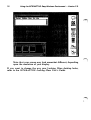
Press I ENTER I . The INTERACTIVE Easy Windows Environ
ment installation is complete and your screen will look similar
to this:
10
Using the INTERACTIVE Easy Windows Environment - Version
2.0
Note that your screen may look somewhat different, depending
upon the resolution of your display.
If you want to change the way your Looking Glass desktop looks,
refer to the INTERACTIVE Looking Glass User's Guide.
Using the INTERACTIVE Easy Windows Environment - Version 2.0
11
5. USING THE EASY WINDOWS ENVIRONMENT
,.,...
For information about using the Motif and Looking Glass environ
ments, refer to the INTERACTWE Looking Glass User's Guide and
the X Window System User's Guide, Motif Edition.
5. 1
Using the Icon Box
If, while installing, you chose to have an icon box, your icons will
be stored in a scrollable box at the bottom of your screen. The icon
box is described in the X Window System User's Guide, Motif
Edition.
5.2 Exiting the Easy Windows Environment
To preserve the Looking Glass environment when exiting Easy
Windows, you must first quit Looking Glass using the System menu
in the Looking Glass window. Then, move the cursor outside any
windows onto the background and hold down the left mouse button
to access the Easy Windows Menu. Select Qu i t from the menu.
You will be returned to the following message:
Pr e s s E S C to abort to a
S t a r t i nq xdm in 3 0 s e c onds .
c o n s o l e q e tty or p r e s s x to s t art xdm i mm e d i at e l y .
Press I ESCI to obtain an INTERACT V
IE
prompt.
U NI X System login
12
Using the INTERACTIVE Easy Windows Environment - Version
2.0
6. TROUBLESHOOTING
•
•
•
•
•
The Easy Windows Environment can only be run from the con
sole. It will not work properly on a terminal.
An insufficient amount of memory (6 MB or less ) may affect the
functionality of the Easy Windows Environment. For example,
changing virtuals terminals rapidly several times in a row on
such a machine may kill your Easy Windows Environment
session.
You must exit the Easy Windows Environment before using the
s hu t d own command to shut down your system.
If the xclock comes up in Eastern Standard Time and you want
to change it to another time zone, you must edit the
/ e t c / d e f a u l t / l o g i n file. For example, if the file entry is
EsT 5 E D T and you are in the Pacific time zone, you should
change the entry to P S T B P DT. The 8 signifies the number of
hours your time zone is off from Greenwich Mean Time.
If something is wrong with your INTERACTIVE X 1 1 environ
ment, it may cause the X 1 1 display manager ( xdm ) to respawn
every 30 seconds. For example, if you have a serial mouse that
is unplugged from the system and you start up the Easy Win
dows Environment, your screen may black out every 30 seconds
and display the startup message. To stop this, do the following:
1.
To break out of the Easy Windows Environment session,
press I ESCI when prompted.
2.
Log in as r o o t ( ignore the blackouts; the system will
respond in spite of them ). Changing the i n i t level by
typing i n i t 2 will stop the blackouts altogether if you
can do so without inconveniencing other users on your
system.
3.
Type s y s adm e a s y s e tup and select option d to delete
your automatic startup files.
4.
Type s hu t d own and then reboot the machine.
5.
Check your INTERACTIVE X l l environment carefully to
make sure it is functioning properly. If you cannot find a
problem there, check your Motif and Looking Glass
environments.
'
Using the INTERACTIVE Easy Windows Environment - Version
2.0
13
7. NOTES FOR ADVANCED USERS
7. 1
What the Easy Windows Environment Provides
The INTERACTIVE Easy Windows Environment modifies the
/ e t c / i n i t t a b file to start an X-based login procedure. Once
the X-based login screen appears and you have logged in, the Easy
Windows Environment scripts automatically bring up the X 1 1 ,
Motif, and Looking Glass software. Either new versions of the fol
lowing files are installed or modifications are made to your existing
files:
•
$ HOME / . Xd e f au l t s
Sets colors and various options for Xll clients.
•
S HOME / . X r e s ou r c e s
Sets colors and message strings printed at login.
•
$ HOME / . mwm r c
Sets u p the Easy Windows Menu. I f you accept the Easy
Windows version of mwmr c , the default button bindings for
mwm r c are used as the default in your X d e f a u l t s file.
•
•
•
S HOME / . x s e s s i on
Sets up the initial environment and starts clients for each user;
uses xp c t e rm rather than x t e rm.
•
$ HOME/Mwm
Motif Window Manager resource configuration file that specifies
colors and options.
•
•
•
•
•
$ HOME / l g / l g c o n f i g
Used to configure the Looking Glass Desktop environment.
$ HOME / l g / l g p r e f
Used to configure the Looking Glass Desktop environment.
$ HOME / l g / l g d e s kt o p
Used to configure the Looking Glass Desktop environment.
S HOME / l g / l g c o l o r s
Used to configure the Looking Glass Desktop environment.
$ H OM E / l g / l g d i rh i s t
Used to configure the Looking Glass Desktop environment.
The Easy Windows Environment also adds /u s r / b i n / X 1 1 to
your P AT H variable in . c s h r c , . l o g i n, or . p r o f i l e , if any
14
Using the INTERACTIVE Easy Windows Environment - Version
2.0
of those files are present in your directory. If none is present, it
creates a . p r o f i l e file.
7.2 Stopping Installation
If you choose to stop the installation after logging in because you
want to continue to use your current system configuration rather
than the Easy Windows Environment, then depending on your
current X 1 1 configuration, one of several actions can happen.
If you are using an xdm start up protocol, the system starts your
INTERACTIVE X 1 1 Runtime System as usual.
If you are using an x i n i t protocol, the system asks the following:
Do you want t o run your
e x i s t i ng
. x i n i t r c when you
log
in
[y] ?
If you press I ENTER I , your
x i n i t r c file is copied to
$ H OME/ . x s e s s i on and the INTERACTIVE X l l Runtime Sys
tem is started. Note that your . pro f i 1 e will not be in effect.
You will have to edit your x s e s s i on file manually to set up the
PATH variable and any other variables that should be in effect
immediately after you log in. If you type n and press l ENTER l , the
system will display a typical xp c t e r m window. Refer to xdm ( l )
for more information.
•
.
8. UPDATING YOUR EASY WINDOWS ENVIRONMENT
If you install a new release of the INTERACTIVE X 1 1 Runtime
System, you will need to reinstall the Easy Windows Environment
diskette.
Using the INTERACTIVE Easy Windows Environment - Version 2.0
15
9. REMOVING THE EASY WINDOWS ENVIRONMENT
To remove the INTERACTIVE Easy Windows Environment, do the
following:
,..._
1.
Exit the Easy Windows Environment.
2.
Run s y s adm e a s y s e tup and select d ( delete ) to return
the i n i t t a b file to its previous state.
3.
Run the s hu t d own command and then reboot your system.
( xdm will no longer be running. )
4.
Run s y s adm r e move pkg and remove the Easy Windows
Environment.
You may want to restore any configuration files you saved or merge
them with the new versions, which will remain in
/ u s r / l i b/ X 1 1 /xdm.
INTERACTIVE Motif*
Window Manager
Version 1.1.1
Release Notes
October 1991
1 . I NTRODUCTION
The
INTERACTIVE
Motif
Window
Manager
is
based
on
OS F j Motif* Revision 1. 1. 1 from the Open Software Foundation*
(O S F* ). It contains the Motif Window Manager (MWM ) which
provides a standard graphical user interface ( GUI) that incorporates
the behavior of the Presentation Manager as well as an X Window
System* intrinsics-based toolkit. The INTERACTIVE Motif Win
dow Manager is a licensed version of Motif that has been optimized
for use with INTERACTIVE X 1 1.
2. DOCUMENTATION
The "INTERACTIVE Motif Window Manager Installation Instruc
tions" included with this release describe how to install the INTER
ACTIVE Motif Window Manager.
An OSF/Motif User's Guide is available for persons wanting to use
the Motif Window Manager. This document can be obtained at
your local bookstore or by contacting Prentice Hall.
In the United States:
Prentice Hall
Englewood Cliffs, New Jersey 07632
Telephone: (20 1 ) 767-5937
Internationally:
Simon and Schuster International Group
66 Wood Lane End
Hemel Hempstead, HP2 4RG, UK
2
INTERACTIVE Motif Window Manager Release Notes - Version
1. 1. 1
3. INCOMPATIBILITY WITH PREVIOUS RELEASES OF THE
MOTIF WINDOW MANAGER
Due to changes in the default colormap for X 1 1 R4, the Motif Window Manager's default behavior for drawing borders on inactive
windows has changed. This will result in a slightly different appearance of inactive windows.
4. CAVEAT
The Motif menus might not pop up when a mouse button is clicked
if I NUM-LOCK I is activated. The keyboard accelerators might not
work if I NUM-LOCK I is activated. Please deactivate I NUM-LOCKI in
these cases when accessing Motif menus and keyboard accelerators.
�
···
INTERACTIVE Motif
Window Manager
Installation Instructions
CONTENTS
1 . OVERVIEW
•
•
•
•
.
•
•
•
•
•
•
•
.
.
•
2. INSTALLING THE INTERACTIVE MOTIF WINDOW
MANAGER
•
•
•
3. DISTRIBUTED FILES
.
.
.
-i-
•
•
•
1
•
•
•
•
•
•
•
•
1
•
.
•
•
•
•
•
•
3
�i
- I
I
I
I
I
I
I
� Ii
I
I
'--·
I
I
I
I
I
I
I
I
I
I
I
I
I
I
I
I
I
I
I
I
I
I
I
I
I
I
I
I
I
I
I
I
I
I
I
I
I
I
I
I
I
I
I
I
I
I
I
INTERACTIVE Motif*
Window Manager
Installation Instructions
1 . OVERVIEW
This document describes the basic requirements and procedures that
are necessary to install the INTERACTIVE Motif Window Manager.
All menus and system messages in this document are applicable for
installation on an INTERACTIVE UNIX* Operating System Version
2.2 or later. If you are installing the INTERACTIVE Motif Window
M anager on an earlier version of the INTERACTIVE UNIX System,
your screen displays may appear different from those shown.
�
The INTERACTIVE Motif Window Manager is installed on your
fixed disk using the s y s a dm utility. It is comprised of the INTER
ACTIVE Motif Window Manager (MWM} and associated resource
files. It uses about 720 kb of disk space and requires that the
INTERACTIVE X l l Runtime System package already be installed.
2. INSTALLING THE INTERACTIVE MOTIF WINDOW
MANAGER
1.
To begin the installation, use the system administration com
mand, s y s a dm, or log in as s y s a dm to access the Main
menu. Your screen will look similar to this:
SYSTEM ADMX N X S TRAT XON
1 d i akmqmt
f i le
3 m a c h i n emgmt
mach i n e management menu
4 p a c k a g emgmt
package
menu
management menu
5 s o f tw a r emgmt
s o f tw a r e
s y s t em s e tup menu
7 t tymgmt
tty management menu
8 u s e rmgmt
user
a
numb e r ,
o r <number>?
2.
management
6 s y a s e tup
Enter
?
d i s k management menu
2 f i l emgmt
for
a
name ,
HELP ,
management menu
management menu
the
i n i t i a l part
of
a
name ,
or
q to QUIT :
Type 5 to access the Software Management menu.
screen will then look similar to this:
Your
2
INTERACTIVE Motif Window Manager Installation Instructions - Version
1 . 1. 1
SOFTWARE MANAGBMBNT
1
i n s t a l l pkg
i n s t a l l new s o f tware package onto bu i l t - i n d i s k
2
l i s t pkg
l i s t p a c k a g e s a l r eady i n s t a l l e d
3 r emovepkg
r emove
4 runpkg
run
Ent e r
?
3.
a numb e r ,
o r <number>?
a
for
previ ously
i n s t a l l e d package
s o f tware package w i thout
name ,
BBLP ,
tbe
•
i n i t i a l part o f
t o GO BAC� ,
f r om bu i l t - i n d i sk
i n s t a l l ing
a name ,
it
or
q to QUI T :
Select option 1, i n s t a l l pkg.
The system will then prompt you for the density of the
diskettes you will use for the installation. Your screen will
look similar to this:
·
E n t e r d e n s i ty of the d i s k e t t e s you a r e
1 ) 1 .2
MB
1 5 1 / 4 " h i gh dens i ty )
2 ) 1 . 4 4 MB
1 3 1 / 2 " h i gh dens i ty )
3 ) 360
Kb
( 5 1 / 4 " l ow dens i ty )
4 ) 720
Kb
( 3 1 / 2 " low dens i ty )
Please
4.
enter # ( 1 - 4 ) ,
default
i n s t a l l i ng f r o m :
1 :
Type the number that corresponds to the type of diskettes you
are using for the installation. The system will then ask you to
insert the first diskette of the subset into the diskette drive.
Your screen will look similar to this:
C o n f i rm
Please
insert
the
f l oppy d i s k
I f t h e p r o g r am i n s ta l l a t i on r e qu i r e s more than one f l oppy
d i s k , be sure t o i n s e r t the d i s k s i n the proper o r d e r ,
s t a r t i ng w i th d i s k numb e r 1 .
A f t e r the f i r s t f l oppy d i s k , i ns truct i on s w i l l b e p r o v i d e d
f o r i n s e r t i ng t h e rema i n i ng f l oppy d i s k s .
S t r i k e E N T E R when r e ady
o r ESC t o s top
5.
Insert the Motif Window Manager diskette into the diskette
drive. The system asks you to confirm that this is the package
you want to install. Press I ENTER I to start the installation
process. The system will display the name of each subset file
on your terminal screen. (The file names listed below may
appear in a different order during your installation. ) The
screen will look similar to this:
�
INTERACTIVE Motif Window Manager Installation Instructions - Version
1. 1. 1
3
I n s t a l l t h e I NTERAC T I V E X 1 1 : INT ERAC T IVE Mot i f W i ndow
Manag e r - Ve r s i on 1 . 1 . 1 p a c k ag e ? ( y ) :
I n s t a l l i ng the INT ERAC TIVE X 1 1 : I N T E RACT IVE Mot i f W i ndow
Mana g e r -Ve r s i on 1 . 1 . 1 .
Copyr i ght ( c ) 1 9 8 9 - 1 9 9 1 I n t e r a c t i v e S y s t e m s C o r po r a t i on
A l l R i gh t s R e s e rv e d
D e r i v e d f r om s o ur c e s d i s t r i bu t e d by the Open S o f tw a r e
Found a t i on , I n c .
( c ) Copyr i gh t 1 9 8 9
Open S o f tw a r e Founda t i on , I n c .
W i th a dd i t i on a l c opyr i gh t s f r om the f o l l ow i ng s o ur c e s :
( c ) C opyr i ght 1 9 8 9
D I G I TAL EQUIPMENT CORPORAT ION
( c ) C opyr i ght 1 9 8 7 , 1 9 8 8 , 1 9 8 9 HEWLETT- PAC KARD COMPANY
( c ) Copyr i ght 1 9 8 8
MAS SACHU S E T T S I N S T I TUTE O F T E C HNOLOGY
( c ) C opyr i ght 1 9 8 8
MI CROSOFT CORP ORAT ION
T h e f o l l ow i ng f i l e s are b e i ng i n s t a l l e d :
/ u s r / b i n /X 1 1 /mwm
/ u s r / l i b / X 1 1 / a pp - d e f au l t s /Mwm
/ u s r / l i b/ X 1 1 / e xamp l e s /Mwm . 2 bw
/ u s r / l i b/X 1 1 / e xamp l e s /Mwm . 4 b l
/ u s r / l i b / X 1 1 / e x a mp l e s /Mwm . 4 br
/ u s r / l i b/ X 1 1 / e x a mp l e s /Mwm . 4 c b
/ u s r / l i b/ X 1 1 / e xamp l e s /Mwm . 4 d t
/ u s r / l i b / X 1 1 / e xamp l e s /Mwm . 4 g
/ u s r / l i b/ X 1 1 / e xamp l e s /Mwm . 4 l g
/ u s r / l i b/X 1 1 / e x a mp l e s /Mwm . 4 l s b
/ u s r / l i b/ X 1 1 / e xamp l e s /Mwm . 4mvr
/ u s r / l i b/ X 1 1 / e xamp l e s /Mwm . 4pg
/ u s r / l i b/ X 1 1 / e xampl e s /Mwm . 4 s b
/ u s r / l i b/ X 1 1 / e xamp l e s /Mwm . 4w
/ u s r / l i b /X 1 1 / e xamp l e s /Mwm . b l
/ u s r / l i b/ X 1 1 / e xamp l e s /Mwm . br
/ u s r / l i b/ X 1 1 / e x a mp l e s /Mwm . cb
/ u s r / l i b/ X 1 1 / e xamp l e s /Mwm . dt
/ u s r / l i b/ X 1 1 / e xamp l e s /Mwm . l s b
/ u s r / l i b/ X 1 1 / e xamp l e s /Mwm . mvr
/ u s r / l i b/ X 1 1 / e xamp l e s /Mwm . pg
/ u s r / l i b/ X 1 1 / e xamp l e s /Mwm . s b
/ u s r / l i b/ X 1 1 / s y s t e m . mwmrc
/ u s r / o p t i on s /xm . name
1 4 1 7 b l o ck s
�
6.
The INTERACTIVE Motif Window Manager is now installed
on your fixed disk.
3. DISTRIBUTED FILES
The INTERACTIVE Motif Window Manager is distributed on one
diskette. The contents of the diskette are copied to the
/ u s r / b i n / X 1 1 and / u s r / l i b / X 1 1 directories on your fixed
disk. This section briefly describes many of the files distributed with
the INTERACTIVE Motif Window Manager.
•
/ u s r / b i n / X 1 1 /mwm
This file is the INTERACTIVE Motif Window Manager. By
default it uses the following files for its configuration
information:
4
INTERACTIVE Motif Window Manager Installation Instructions - Version
1. 1. 1
/ u s r / l i b / X 1 1 / s y s t e m . mwmr c
This 'file contains the default definitions of the menu system,
the button bindings, and the key bindings in the INTER
ACTIVE Motif Window Manager.
/ u s r / l i b / X 1 1 / a pp - d e f a u l t s /Mwm
This file contains the default color, font, and resource
definitions for the INTERACTIVE Motif Window Manager.
•
/ u s r / l i b / X 1 1 / e xamp l e s /Mwm . *
These files contain additional example color and resource
definitions for the INTERACTIVE Motif Window Manager:
•
•
•
•
The file Mwm . 2 bw is the default two-color binding.
The files Mwm . 4 * show a few of the possible four- or five
color bindings.
The remaining files show the other eight- and nine-color
combinations for the INTERACTIVE Motif Window
Manager.
The files Mwm . c b and Mwm . b l are generally considered
the two most frequently used INTERACTIVE Motif Window
Manager default color combinations.
Character Bitmap Distribution Format
CONTENTS
1. INTRODUCTION .
2. FILE FORMAT . .
1
1
3.
3
M ETRIC INFORMATION .
4. AN EXAMPLE FILE .
6
.
- i -
�
...______
/
·.
� .
'-._ . /
'
Character Bitmap Distribution Format
fii'
',
1 . INTRODUCTION
This document describes the Character Bitmap Distribution Format
( BDF), Version 2. 1 . BDF is an X Consortium standard for font
interchange, intended to be easily understood by both users and
computers.
2. FILE FORMAT
Character bitmap information is distributed in an USASCII
encoded, user-readable form. Each file is encoded in the printable
characters (octal 40 through 1 76) of USASCII plus a carriage return
and a line-feed character. Each file consists of a sequence of
variable-length lines. Each line is terminated by a carriage-return
(octal 0 1 5 ) and a line-feed character (octal 0 1 2) or by just a line
feed character.
The information about a particular family and typeface at one size
and orientation is contained in one file. The file begins with infor
mation pertaining to the typeface as a whole, followed by the infor
mation and bitmaps for the individual characters.
A font bitmap description file has the following general form, where
each item is contained on a separate line of text in the file. Items on
a line are separated by spaces.
1.
The word S T ARTFONT followed by a version number indicat
ing the exact file format used. The version number described
here is 2 . 1 .
2.
One or more lines beginning with the word C OMMEN T . These
lines may be ignored by any program reading the file.
3.
The word FONT followed by the full name of the font. Note
that the name continues all the way to the end of the line, and
it may contain spaces.
4.
The word S I Z E followed by the point size of the characters,
the x resolution , and the y resolution of the device for which
these characters are intended.
2
Character Bitmap Distribution Format
5.
The word F O N T B OUN D I NGBOX followed by the width in x,
height in y, and the x and y displacement of the lower left
hand corner from the origin . (See the examples in section 4. )
6.
Optionally the word S T ART P R O P E R T I E S followed by the
number of properties (p ) that follow.
7.
Then come p lines consisting of a word for the property name
followed by either an integer or string surrounded by double
quotes (octal 042). Internal double-quote characters are indi
cated by using two in a row.
8.
Properties named
9.
The
�
F O N T A S C E N T, F O N T D E S C E N T ,
and
should be provided to define the logical
font-ascent and font-descent and the default-char for the font.
These properties will be removed from the actual font proper
ties in the binary form produced by a compiler. If these
properties are not provided, a compiler may reject the font or
may compute (arbitrary) values for these properties.
D E F AU L T
C HAR
property
section,
E N D P R O P E RT I E S .
if it
exists,
is
terminated
by
1 0.
The word C HA R S followed by the number of character segments ( c ) that follow.
1 1.
Then come c character segments of the form:
a.
The word S TA R T C HAR followed by up to 1 4 characters
(no blanks) of the descriptive name of the glyph.
b.
The word E N C O D I NG followed by a positive integer
representing the Adobe* Standard Encoding value. If
the character is not a member of the Adobe Standard
Encoding, E N C O D I NG is followed by - 1 and an
optional integer specifying the glyph index; if the glyph
index is not specified, a compiler will typically ignore the
character segment.
c.
The word S W I D T H followed by the scalable Width in x
and y of character. Scalable widths are in units of
1 / 1 000th of the size of the character. If the size of the
character is p points, the width information must be
scaled by p / 1 000 to get the width of the character in
printer's points. This width information should be considered as a vector indicating the position of the next
character's origin relative to the origin of the current
�
l
3
Character Bitmap Distribution Format
character. To convert the scalable width to the width in
device pixels, multiply S W I D T H times p /1000 times
r / 1 2, where r is the device resolution in pixels per inch.
The result is a real number giving the ideal print width
in device pixels. The actual device width must of course
be an integral number of device pixels; it is given in the
next entry. The S W I D T H y value should always be zero
( 0 ) for a standard X font.
d.
The word DW I D T H followed by the width in x and y of
the character in device units. Like the S W I D T H , this
width information is a vector indicating the position of
the next character's origin relative to the origin of the
current character. The DW I D T H y value should always
be zero for a standard X font.
e.
The word B B X followed by the width in x (BBw ) , height
in y (BBh ) , and x and y displacement (BBox, BBoy) of
the lower left-hand corner from the origin of the
character.
f.
The optional word A T TR I BU T E S followed by the attri
butes as 4 hex- encoded characters. The interpretation of
these attributes is not defined in this document.
g.
The word
h.
h lines of hex-encoded bitmap, padded on the right with
B I T MA P .
zeros to the nearest byte, that is, a multiple of 8.
i.
1 2.
The word
E N D C HAR.
The file is terminated with the word
ENDFONT.
3. METRIC INFORMATION
Figures 1 and 2 best illustrate the bitmap format and character
metric information.
4
Character Bitmap Distribution Format
...,_ BBox
BBw
...
I�
I�
I�
.� � � �
I� I� I�
I�
1 � 1� 1�
1� 1�1�
�� ��� �
�� � ��
I� �� �
� �� �
B Boy
� I W m.
i0l 1 � rh
B Bh
BBw
I�
��
� I� I�
I�
I� I� I�
I � I�
I�
9, BBh 22, BBox -2, BBoy
Rounded character width
8 0
"+" character origin and width
=
=
=
=
=
=
Figure 1. An Example of a Descender
-6
5
Character Bitmap Distribution Format
----4
�
..
BBox
..
..
BBw
��
�
.
��
�
.
BBh
���
��
��
��
�
� �
.
B Boy
BBh
=
+
+
6, BBw 4, BBox +2, BBoy
Rounded character width 5 0
=
=
=
+12
=
Figure 2.
An Example With the Origin Outside the Bounding Box
6
Character Bitmap Distribution Format
4. AN EXAMPLE FILE
Figure 3 is an abbreviated example of a bitmap file containing the
specification of two characters (the j and quot e r i ght in 4).
S TARTFONT @v a l u e ( f o rmatv e r s i on )
C OMMENT Th i s i s a s a m p l e font i n 2 . 1 format .
FONT H e l v e t i c a - B o l d
SIZE 8 2 0 0 2 0 0
FONTBOUN D I NGBOX 9 2 4 - 2 - 6
S TARTPRO P E R T I E S 2
Mi nSpace 4
C o pyr i ght " C opyr i ght ( c ) 1 9 8 7 Adobe S y s t e m s ,
ENDPROPE R T I E S
CHARS 2
S TARTCHAR j
E N C O D I NG 1 0 6
SWIDTH 3 5 5 0
DWIDTH 8 0
BBX 9 2 2 - 2 - 6
B I TMAP
0 380
0 380
0 380
0 380
0000
0700
0700
0700
0700
OEO O
OEOO
OEOO
OEOO
OEOO
1COO
1COO
1 C0 0
1COO
2COO
7800
FO O O
EOOO
ENDCHAR
S TARTC HAR quot e r i ght
ENCOD I NG 3 9
SWIDTH 2 2 3 0
DW I D T H 5 0
BBX 4 5 2 1 2
ATTR I BU T E S 0 1 C O
B I TMAP
70
70
60
EO
Inc . •
co
ENDC HAR
E N D FONT
Figure 3.
A Short Example File
INTERACTIVE X11 Installation Instructions
and Maintenance Procedures
CONTENTS
1. INTRODUCTION
l.I Overview of This Document
1 . 2 What Will I Learn From This Document? .
•
.
.
.
•
1
1
.
2
3
3
2. GETTING STARTED
2.I Hardware Requirements
2. 2 Installation Using the System Administration
Menu
.
4
3. SYSTEM PACKAGES
3.I Runtime System
.
3. 2 Development System
3.3 Contributed Software
3.4 Server Kit .
5
5
5
5
5
.
.
.
.
.
•
.
•
•
.
.
•
.
•
.
.
.
.
.
•
.
.
.
.
4. INSTALLING INTERACTIVE XII
4.I Removing Previous Releases of XII
4. 2 Installing the Runtime System
4. 3 Installing the Development System
4.4 Installing the Contributed Software .
•
•
•
•
•
•
.
•
•
•
.
•
.
•
•
.
.
•
.
•
•
•
.
.
.
•
.
•
.
.
.
-i-
.
.
•
.
.
.
.
6
6
6
20
22
26
26
26
28
30
31
32
34
35
37
•
•
.
.
5. CONFIGURATION AND MANAGEMENT
PROCEDURES
5.I Per-User XII Configuration
5. 1.I Adding Xl l Users
5. 1.2 Deleting XII Users
5. 2 X Host Management
5.2.I Listing Remote Hosts
5.2. 2 Adding Remote Hosts
5.2. 3 Deleting Remote Hosts
5. 3 Display Configuration
5. 3.I Listing a Display Configuration
5. 3.2 Adding or Modifying a Display
Configuration .
.
5. 3. 3 Deleting a Display Configuration .
5.4 Server Management
.
5.4.I Listing Servers
.
•
.
.
.
38
45
46
48
5.4.2 Adding Servers
5.4. 3 Deleting Servers
5. 5 Configuring X 1 1 Drivers
5. 5. 1 Using s y s adm to Configure X 1 1
Drivers
0
0
0
0
0
0
0
0
0
0
0
0
0
0
0
0
0
0
0
6 . RUNNING INTERACTIVE X 1 1
6. 1 Running the Server
6.2 Using the Development System
0
0
0
0
0
0
0
0
0
7. REMOVING X 1 1 SYSTEM PACKAGES
0
0
0
0
0
0
0
0
0
0
0
51
57
57
57
0
0
0
0
0
0
0
0
0
0
0
0
0
0
0
0
0
0
8. KERNEL CONSIDERATIONS
8. 1 Adding Drivers to Your INTERACTIVE UNIX System
Kernel System File
8. 2 Adding Kernel Resource Settings to Your
INTERACTIVE UNIX System Kernel Systems
File
8. 3 MSC Technologies Bus Mouse
8.4 Troubleshooting Potential Kernel Resource
Problems
0
0
0
0
0
0
0
0
0
0
0
0
0
0
0
0
0
0
0
0
0
0
0
0
0
0
0
0
0
0
0
0
0
0
0
0
0
49
50
51
0
0
0
0
0
0
0
0
0
0
0
0
0
0
0
0
0
0
0
0
0
0
0
�
58
61
6"1
61
61
61
�
- ii -
INTERACTIVE X11 Installation Instructions
and Maintenance Procedures
1 . INTRODUCTION
This document describes the basic requirements and procedures that
are necessary to install INTERACTIVE X l l .
All menus and system messages in this document are applicable for
installation on the INTERACTIVE UNIX* Operating System, Ver
sion 2.2 or later.
Once you have completed the basic system installation, refer to sec
tion 5 in this document to learn how to configure user profiles,
install and configure servers, and tailor the system to match your
requirements.
1 .1
Overview of This Document
This document is divided into eight major sections:
r-.
1 . INTRODUCTION
This section provides a general overview of this
document.
2. GETTING STARTED
This section discusses hardware and software considera
tions, and provides an overview of the system adminis
tration menu ( s y s a dm).
3. SYSTEM PACKAGES
This section describes the INTERACTIVE X 1 1 packages.
4. INSTALLING INTERACTIVE X l l
This section explains how to install the system. It also
describes how to perform the preliminary setup pro
cedures that are required to use the system once it is
installed.
2
INTERACTIVE X1 1 Installation and Maintenance - Version 2.0
5 . CONFIGURATION AND MANAGEMENT PROCEDURES
This section discusses building new servers, removing
servers, making default servers, modifying configuration
information, installing new X device drivers, adding X
users, and deleting X users.
6. RUNNING INTERACTIVE X 1 1
This section explains how to run X 1 1 .
7. REMOVING X l l SYSTEM PACKAGES
This section describes how to remove X l l system packages from the system.
8. KERNEL CONSIDERATIONS
This section provides suggestions for making sure your
kernel has the required facilities to run X.
1 .2 What Will I Learn From This Document?
This document provides step-by-step instructions designed to help
you install and maintain INTERACTIVE X 1 1 . This document
describes:
•
•
•
The component system packages of INTERACTIVE X 1 1 .
The basic installation and setup procedures (most are performed
automatically by the system).
The configuration and maintenance procedures for managing
INTERACTIVE X 1 1 after it is installed.
•
How to remove system packages from your system.
•
The kernel considerations for running X 1 1 .
l
INTERACTIVE X1 1 Installation and Maintenance - Version 2.0
3
2. GETTING STARTED
Before you install INTERACTIVE X 1 1 on your computer, you must
complete the following tasks:
1.
Read the "INTERACTIVE X l l Release Notes" in this guide
for any additional information required to install the release.
2.
Assemble and set up your hardware.
3.
Ensure that the INTERACTIVE UNIX System, the Kernel
Configuration subset, and the STREAMS Facilities subset are
installed on your system.
4.
If you plan to use the VP f ix* Environment, it should be
installed prior to installing INTERACTIVE X 1 1.
5.
Running X 1 1 across the network currently requires INTER
ACTIVE TCP fiP ( Transmission Control Protocol/Internet
Protocol ). If you want to use the INTERACTIVE TCP /IP
facilities, this extension must be installed on your system.
Note that this does not apply to local connections. Currently
the s o c k e t library as supplied runs only with INTER
ACTIVE TCP fiP. The InterLan* networking software is not
supported under X l l .
6.
I f you are installing the INTERACTIVE X 1 1 Development
System, the INTERACTIVE Software Development System
extension must be installed on your system.
After verifying these steps, you will be ready to install INTER
ACTIVE X 1 1.
2.1
Hardware Requirements
To determine the INTERACTIVE X 1 1 -specific hardware informa
tion you need to install and run X, refer to the "INTERACTIVE
X ll Release Notes."
Compare these requirements with your hardware configuration.
Make sure that you have available at least the minimum
configuration. Then follow the manufacturer's instructions to deter
mine how to assemble and attach all components for operation.
4
INTERACTIVE
X1 1 Installation and Maintenance - Version 2.0
2.2 Installation Using the System Administration Menu
The system administration menu ( s y s adm) can be used to perform
the installation. You must use the console terminal to log in as
s y s a dm, and you will be asked for the password assigned to
s y s a dm.
�
INTERACTIVE X1 1 Installation and Maintenance - Version 2.0
5
3. SYSTEM PACKAGES
�
INTERACTIVE X l l is installed as an extension on the INTER
ACTIVE UNIX System. The following subsections briefly describe
the system packages that comprise this extension.
3.1
Runtime System
The Runtime System allows the user to invoke and utilize the X
environment. It consists of the Clients, the System and Servers
( which includes the VGA server, kernel driver, system administra
tion scripts, and server configuration facilities ) , and the Display
Servers I and II ( which includes servers other than the VGA
servers ). This system package is intended for users who want to use
the X environment, but who do not plan to develop X client applica
tion programs ( clients ). The user cannot develop or build X clients
with this package because the required libraries and i n c 1 u d e files
are not present. The Runtime System must be present before any
other X 1 1 system packages are installed.
3.2 Development System
The Development System must be installed after the Runtime Sys
tem package. It contains the necessary libraries and i n c l ud e
files to develop X clients. This system package is designed for
developers of INTERACTIVE X 1 1 applications.
3.3 Contributed Software
The Contributed Software is included with the Development Sys
tem. It contains a number of client programs and fonts from the
user-contributed part of the MIT tape and can be installed any time
after the Runtime System is installed. The installation of this sys
tem package is optional and it is provided on an as-is basis. This
software is unsupported, and it may not run on all configurations.
Documentation for the Contributed Software is supplied on-line in
the / u s r / m a n / m a nn directory.
3.4 Server Kit
The Server Kit must be installed after the Development System
package. It is intended for developers who would like to develop an
INTERACTIVE X l l server. The Server Kit is only available to
qualified developers. Please contact the INTERACTIVE X 1 1 Product
Manager or your sales representative for further information.
6
INTERACTIVE
X1 1 Installation and Maintenance - Version 2.0
4. INSTALLING INTERACTIVE X1 1
Follow all of the steps given below. You must use the console ter
minal to log in as s y s a dm, and you will be asked for the password
assigned to s y s a dm. Experienced UNIX System users can log in
to the console terminal as r o o t and perform these same tasks from
the command line.
�
INTERACTIVE X 1 1 Version 2.0 will install on the INTERACTIVE
UNIX Operating System, Version 2.2 or later.
You can overlay INTERACTIVE X l l Version 2.0 on a previous
release of X 1 1 if one is currently installed.
You should not be in the X 1 1 environment at the time you install
( overlay ) Version 2.0, because this will cause certain files that must
be updated to be inaccessible.
4.1
Removing Previous Releases of X1 1
It is recommended that you do not remove previous X 1 1 releases,
but overlay Version 2.0 on top instead. Refer to the release notes
for information on saving any existing files that you may have
modified.
4.2 Installing the Runtime System
To install the Runtime System package software on an INTER
ACTIVE UNIX System:
Use the s y s a dm command or log in as s y s adm and access
the Main menu. Your screen will look similar to this:
1.
SYSTEM ADM I N I S TRAT I ON
1
d i akmgmt
d i s k management menu
2 f i l emgmt
3 m a c b i n e mqmt
2.
manaqement menu
4 p a c k a g e mgmt
5 a o f tw a r emgmt
p a c k a g e management menu
6
s y s t em s e tup menu
s o f tw a r e management menu
a ya a e tu p
7 t tymgmt
tty
8 u s e rmgmt
user
Enter a
?
f i le
m a c h i n e management menu
numb e r ,
o r <number>?
a
management menu
name ,
f o r BBLP ,
management menu
the
i n i t i a l part o f
a name ,
or
q to QOI T :
Type q at any time to quit the current operation. If a ?
appears as a choice, type ? for help.
�
INTERACTIVE X1 1 Installation and Maintenance - Version 2. 0
7
option 5 to access the Software Management
( s o f t w a r e mgmt) menu. Your screen will look similar to
Select
this:
SOPTWARB MAHAGBMBRT
1
i n a t a l l pl<g
install
2
l i a tpl<g
l i s t package s
3.
a l r e ady
onto bu i l t - i n d i a l<
installed
3 r e movepl<g
r emove p r e v i ou s l y i n s t a l l e d p a c k a g e
4 runpl<g
run
Ent e r
?
new s o f tware package
a
numbe r ,
o r <numb er>?
a
s o f tw a r e package w i thout
name ,
the
f o r HBLP ,
•
a
f rom bu i l t - i n d i al<
i n s ta l l i ng
i n i t i a l part
of
to GO BACK ,
q to QU I T :
name ,
it
or
Select option 1, i n s t a l l pkg.
The system will then prompt you for the density of the
diskettes you will use for the installation. Your screen will
look similar to this:
E n t e r d e n s i ty of the d i s k e t t e s you a r e
1 ) 1 . 2
MB
5 1 / 4 " h i gh d e n s i ty )
2 ) 1 . 4 4 MB
( 3 1 / 2 " h i gh d e n s i ty )
Kb
( 5 1 / 4 " l ow d e n s i ty )
3 ) 360
( 3 1 / 2 " l ow d e n s i ty )
4 ) 720
Kb
P l e a s e e nt e r # ( 1 - 4 ) ,
4.
d e f au l t
1 :
i n s t a l l i ng f r om :
i
r
Type the number that corresponds to th type o diskettes you
are using for the installation, or press ENTER to accept the
default. The system will then ask you to insert the first
diskette of the Runtime System into the diskette drive. Your
screen will look similar to this:
C o n f i rm
Please
i n s e r t the
f l oppy d i s k
I f t h e p r o g r a m i n s ta l l a t i on r e qu i r e s more than o n e f l oppy
d i s k , b e sure t o i n s e r t the d i s k s i n the proper o r d e r ,
s t a r t i ng w i th d i s k numb e r 1 .
A f t e r the f i r s t f l oppy d i s k , i n s tru c t i on s w i l l b e p r ov i d e d
f o r i n s e r t i ng t h e r e ma i n i ng f l oppy d i s k s .
S t r i k e ENTER when r e ady
or E S C t o stop
5.
If you wish to stop the installation process and return to the
system prompt, press I ESC I . To proceed with the installation,
insert the first Clients diskette into the drive and press
I ENTER I . The following message will be displayed:
8
INTERACTIVE
X1 1 Installation and Maintenance - Version 2.0
I n s t a l l a t i on i s in progr e s s - - do not r e move the f l oppy d i s k .
I n s t a l l the INT ERAC T I VE X) 1 : Runt i m e S y s t e m C l i en t s V e r s i on 2 . 0 p a c k ag e ?
( y/ n ) :
6.
Type y to proceed with the installation of the Clients subsystern. ( You can type n to stop the installation. ) If you type
y, your screen will look similar to this:
I n s t a l l i ng the I NTERACTIVE X 1 1 : Runt i m e S y s t e m - C l i en t s
V e r s i on 2 . 0 .
Copyr i gh t ( c ) 1 9 8 8 - 1 9 9 1 Inte r a c t i ve S y s t e m s Corpo r a t i on
A l l R i gh t s R e s e r v e d
�
-
D e r i ve d f r om X 1 1 R4 s o ur c e s d i s t r i bu t e d b y M I T
C opyr i gh t 1 9 8 5 - 1 9 8 9 by the Ma s s a c hu s e t t s Ins t i t u t e o f
T e c hno l ogy a n d othe r s .
R e f e r to / u s r / l i b/X 1 1 /LABEL f o r
a c o mp l e t e l i s t .
The
7.
f o l l ow i ng
f i l e s a r e be i ng
instal l ed :
A list of the files being copied onto your system from the first
diskette will accompany the above message. When all files
from the first diskette have been copied, the system will
prompt you to insert the second diskette:
F l oppy d i s k e t t e numb e r 1 i s comp l e t e
Remove f l oppy a n d i n s e r t f l oppy numbe r 2
Type <e n t e r> when r e ady :
8.
Insert the second diskette into the diskette drive and press
I ENTER I . A list of the files being copied onto your system
from the second diskette will be displayed on your screen.
9.
Continue inserting diskettes until all of the diskettes have been
copied. When the last diskette has been copied, the following
message will be displayed:
I n s t a l l a t i on of I NTERACT I VE X 1 1 :
V e r s i on 2 . 0 i s compl e t e .
1 0.
Runt i m e S y s t e m -
C l i en t s
-
Insert the first System and Servers diskette and press
I ENTER I . Your screen will look similar to this:
I n s t a l l i ng I NTERAC T IVE X 1 1 : Runt ime S y s t e m S y s t e m and S e rve r s - V e r s i on 2 . 0
T h e f o l l ow i ng f i l e s a r e b e i ng i n s ta l l e d :
1 1.
Continue inserting the System and Servers diskettes until they
have all been copied. After the files from the diskettes have
been installed, your screen will look similar to this:
I n s t a l l a t i on of a b a s i c X 1 1 s y s t e m i s c ompl e t e .
Do you p l an to u s e a
s t an d a r d VGA d i s p l a y or a 2 5 6 - c o l or VGA d i s p l a y ?
[ Y i n, q ]
�
9
INTERACTIVE X1 1 1nstallatlon and Maintenance - Version 2. 0
1 2.
If you plan to run a VGA server, you can respond y and
configure your server at this time by skipping to step 1 6.
13.
If you plan to run a server other than a VGA, then you must
now install the appropriate server from the Display Servers I
and II diskettes. To do this, repeat steps 5 through 9, this
time using the Display Servers I and II diskettes.
If you used Display Servers
this:
I,
your screen will look similar to
I n s t a l l a t i on is in progr e s s -- do not r e move the
Th i s P a c k a g e Cont a i n s the f o l l ow i ng :
1 •
2.
3.
4.
5.
6.
7.
I N T ERAC T I V E
I N T E RAC T I VE
I N T ERAC T I V E
I N TERAC T I V E
I NTERAC T I V E
I N T ERAC T IVE
I N T ERAC T IVE
X1
X1
X1
X1
X1
X1
X1
1
1
1
1
1
1
1
:
:
:
:
:
:
:
f l oppy d i s k .
Corne r s tone S e rv e r
I BM 8 5 1 4 /A S e r v e r
Hercul e s Server
S i gma D e s i gn s L a s e r v i e w S e rv e r
P i xe lworks S e r v e r
Mon i t erm V i k i ng 2 1 / 9 1 S e rv e r
B e l l T e c h WGE B l i t S e r v e r
Ent e r a l i s t o f numb e r s s e p a r a t e d by s p a c e s f o r tho s e modu l e s
y o u want t o i n s t a l l , o r e n t e r " n " f o r NONE , o r e n t e r " a l l " t o
i n s t a l l A L L modul e s :
1 4.
Select the server or servers you want to use. If, for example,
you enter 3 to install the Hercules• server, your screen will
look similar to this:
I n s t a l l i ng I N TERAC T IVE X 1 1 : H e r c u l e s S e rv e r - V e r s i on 2 . 0
T h e f o l l ow i ng f i l e s a r e b e i ng i n s t a l l e d :
I n s t a l l a t i on of the " I NTERACT I V E X 1 1 : H e r c u l e s S e r v e r In o r d e r to u s e X 1 1
V e r s i on 2 . 0 " s ub s e t i s now compl e t e .
w i th th i s d i s p l ay , the s e rver mu s t be bu i l t and t h e
d r i v e r mu s t b e c o n f i gu r e d i nt o the k e r ne l .
Do you want to do th i s now?
[y, n, q]
1 5.
At this point you must determine whether you would like to
configure a server. Before you can use X 1 1 , you will need to
create your display server configuration entries. If servers are
configured that require drivers, the system will also configure
the appropriate driver at this time. To configure a server, type
y.
If you press n, the system will display:
Th i s s e rv e r w i l l b e unava i l a b l e for u s e unt i l you e x e c u t e
" s ys adm c o n f i gmgmt " , " s ys adm s e rve rmgmt " ,
" s y s a dm xdr i v e rmgmt " , and " k c on f i g " t o c o n f i gu r e t h e s e rv e r ,
bu i l d t h e s e r v e r , conf i gu r e the d r i v e r , and b u i l d the k e r ne l ,
r e s p e c t i ve l y .
1 6.
If you typed
y,
the system will automatically start up the
Display 0 is usually
c on f i gmgmt utility for display 0 .
10
INTERACTIVE X1 1 Installation and Maintenance - Version 2.0
considered
the
default
console
display
for
X.
The
c on f i gmgmt utility will present a series of menus and ques
tions regarding the hardware configuration for this display. In
most cases, the default selection, [ s hown i n b r a c k e t s ] ,
will be the correct choice. If you need additional information
to make your selection, you should refer to xconfig( 1 ),
Xconjig(5 ), and the server-specific manual entries in this guide
for additional configuration information. (The server-specific
manual entries are those Section 1 entries in which the entry
names begin with an uppercase X. ) You can refer to section
5 . 3 for additional information on listing, adding, and deleting
configuration entries.
�
Your screen will look similar to this:
Ent e r
the
o p e r a t i on you want to p e r f orm :
1 l i st
2 add
3 delete
[ d e f au l t :
17.
q] :
Type 2 to add servers. Your screen will look similar to this:
Ent e r d i s p l ay numb e r ( ' 1 ' for l i s t , ' q ' to qu i t )
D i s p l ay • o • d o e s n ' t e x i s t , c r e a t e i t ? [ y ] :
1 8.
[0] :
Press I ENTERI to choose display 0 and create it:
C r e a t e d i s p l ay • o • :
S e l e c t r e s ou r c e t o add :
d i s p l ay
1
keyboard
2
mouse
3
4
tablet
( s e l e c t ' 1 ' t o l i s t , ' q ' to qu i t )
Enter
1 9.
s e l e c t i on
[ d i s p l ay ] :
When a menu has a default selection, that choice is shown in
brackets in the line at the bottom of the screen that says
E n t e r s e l e c t i on [ selection ] . If you want to select the
default resource d i s p l ay in the above screen, press
! ENTER I . (You could also type either the option number ( 1 )
or the selection name ( d i s p 1 a y ). ) If you want to select a
resource other than d i s p 1 ay, you may type either the
option number ( 2 , 3 , or 4 ) or the selection name
( k e yb o a r d , mou s e , or t a b l e t ) of that resource. The X
configuration procedures will automatically cycle through all
of the resource options.
�
INTERACTIVE X1 1 Installation and Maintenance - Version 2.0
11
When configuring your resources, note that your display and
the information requested will vary according to the display
type you select.
rir
Note that you cannot include both a mouse and a tablet
in the same configuration.
If you have installed the Display Servers I diskette and you
select the d i s p 1 a y option, your screen will look similar to
this:
S e l e c t d i s p l ay type :
1
eve
C o r n e r s tone D i s p l ay s ( and compat i b l e s )
2
8514
I BM 8 5 1 4/A D i s p l ay Adapt e r and c ompa t i b l e s
H e r c u l e s mono chrome d i s p l a y
3
HRC
4
LVP
S i gma D e s i gns L a s e r V i e w
5
V2 5 6
VGA and c ompat i b l e s ( 2 5 6 C o l o r s )
6
VGA
VGA and c ompa t i b l e s
EGA and c ompat i b l e s
7
EGA
8
VIKING
Mon i t erm V i k i ng
( s e l e c t ' q ' to qu i t )
E n t e r s e l e c t i on
rir
[ VGA ] :
If you have also installed the Display S ervers II diskette
on your system, your menu will include choices in addi
tion to those listed above that are available for install
ation with this release.
If you are overlaying X l l Version 2.0 on top of Release
1 . 3 , your menu will include additional choices not listed
above. However, only the choices shown above are avail
able for installation with this release.
20.
Type the option number or the name that corresponds to the
type of display you are using. For example, to select the
default, VGA, press I ENTER I , or type 6 or VGA. I f you select
the VGA display type, your screen will look similar to this:
12
INTERACTIVE X1 1 Installation an d Maintenance - Version 2.0
S e l e c t VGA b o a r d Manuf a c t ur e r :
1
ATI
2
C ompuAdd
3
De l l
4
Genoa
5
I BM ( or o t h e r b a s i c VGA )
6
M i crol abs
7
Orch i d
8
Parad i s e
Quadram
9
10
S i gm a
1 1
STB
12
SunR i ve r
13
T a tung
T e chmar
14
15
T s eng
T r i dent
16
17
V i d e o 7 ( He a d l and )
E nt e r s e l e c t i on
21.
[ I BM ] :
Type the option number or the name that corresponds to the
manufacturer of the VGA display ou are using. For example,
to select the default, I BM, press ENTER , or type 5 or I BM.
If you select the I BM display type, your screen will look simi
lar to this:
S e l e c t VGA d i s p l ay type :
1
VGA
B a s i c 6 4 0 x 4 8 0 VGA
2
VGAPAN
Pann i ng VGA
E nt e r s e l e c t i on
22.
[ 1 ] :
Enter the VGA display type you are using. For example, to
select the default, VGA, press I ENTERI or type 1 . If you
select the B a s i c 6 4 0 x 4 8 0 VGA display type, your screen
will look similar to this:
S e l e c t num b e r of c o l o r p l a n e s t o u s e :
1 p l an e
( 2 colors )
1
2 p l an e s ( 4 c o l o r s )
2
3
4 planes ( 1 6 colors )
Ente r
23.
s e l e c t i on
[3) :
Type the option number that corresponds to the number of
planes you are using. To select the default number of planes
(option 3 ), press I ENTER I . Your screen will look similar to
this:
Ente r s c r e e n s i z e
24.
( i n i n ch e s )
in the
f o rm W I DTHxH E I GH T
[ 1 1 x8 ] :
Type the size of the screen in whole inches, or press I ENTER I
to select the default screen size ( 1 1 x 8). Your screen will
look similar to this:
�
INTERACTIVE X1 1 Installation and Maintenance - Version 2.0
E n t e r f u l l pa thname to s c r e e n d ev i c e
25.
13
[ / dev/ c on s o l e ] :
Enter the path name of the screen device, or press I ENTER I to
select the default path name ( / d e v / c on s o l e ) .
If you are using a SunRiver* display, SunRiver workstations
are specified in the configuration file by indicating the
SunRiver device name in place of / d e v/ c on s o l e , that is,
/ d e v/ s t O O for the first SunRiver display, / d e v/ s t O 1
for the second, etc. Refer to the Xvga ( 1 ) manual entry in this
guide for additional information on SunRiver device names.
For information on the SunRiver keyboard display driver and
SunRiver serial ports, refer to skd(1) and sasy ( 1 ) in the
INTERACTIVE UNIX System User's/System Administrator's
Reference Manual .
Your screen will look similar to this:
S e l e c t r e s ou r c e to add :
d i s p l ay
1
keyboard
2
mou s e
3
tablet
4
( se l e c t ' 1 ' to l i st , ' q ' to qui t )
Ent e r s e l e c t i on
26.
[ keyboard ] :
The display resource has now been configured. The next
resource, k e yb o a r d, has been automatically selected as the
next default selection. If you made a mistake in your display
selection and wish to edit the display resource again, type 1 or
d i s p l ay; otherwise press I ENTER I to select the default
option ( k e yb o a r d ) . If you select the k e yb o a r d option,
your screen will look similar to this:
1
AT
S t andard P C /AT keyboard
2
WY6 0
Wys e 6 0 t e r m i n a l i n s c an c o d e mode
( s e l e c t ' q ' to qui t )
Enter
27.
s e l e c t i on
[ AT ] :
Type 1 or press I ENTER I to select the AT keyboard type.
Your screen will look similar to this:
E nt e r keyboard type :
1
1 0 1 keys
2
84 keys
E n t e r s e l e c t i on
28.
( w i th s ep a r a t e a r r ow k e y s )
( e s c a p e key above numb e r p a d )
[ 101 ] :
Type the option that corresponds to the number of keys on
your IBM* AT*-style keyboard. You can press ! ENTER! to
accept the default ( 1 0 1 ). If you do not know whether you
14
INTERACTIVE X1 1 1nstallation and Maintenance - Version 2. 0
have an 84- or 1 0 1 -key keyboard, you can use the following
scheme to determine which type you have:
•
•
29.
If your keyboard has arrow keys that are separate from the
ones on the numeric keypad, then you have a 1 0 1 -key
keyboard.
If the arrow keys on your keyboard are located on the
numeric keypad only, then you have an 84-key keyboard.
After you have made your selection, your screen will look
similar to this:
E n t e r keyboard d ev i c e name ( f rom the manua l
( / d e v / c o n s o l e : /dev/vtK0 2 d ] :
30.
�
entry )
Press l ENTERl to select the default keyboard device name,
unless you are using a SunRiver display.
If you are using a SunRiver display, the keyboard device
name
for
the
first
workstation
is
/ d e v / s t O O : / d e v/ s t 0 %d. A second SunRiver worksta
tion would have / d ev/ s t 1 0 : / d ev/ s t 1 %d specified as
the device name, etc. Refer to Xvga(l) in this guide for additional information on SunRiver device names. For information on the SunRiver keyboard display driver and SunRiver
serial ports, refer to skd(1) and sasy(1) in the INTERACTIVE
�
UNIX System User'sfSystem Administrator's Reference
Manual.
After selecting the keyboard device name, your screen will
look similar to this:
S e l e c t r e s o u r c e t o add :
d i s p l ay
1
keyboard
2
mou s e
3
tablet
4
( s e l e c t ' 1 ' t o l i s t , ' q ' to qu i t )
Ent e r
31.
s e l e c t i on
[ mo u s e ] :
The keyboard resource has now been configured. The next
resource, mou s e , has been automatically selected as the next
default selection. If you made a mistake in your keyboard
selection and wish to edit the keyboard resource again, type 2
or k e yb o a r d; otherwise press lENTERl to select the default
option ( mo u s e ) .
�
INTERACTIVE X1 1 Installation and Maintenance - Version 2.0
15
IIF' Due to hardware considerations, in certain cases, the
configuration information you choose for a mouse might
not be related to the actual brand name of the mouse you
have. For example, the LOGITECH* two-button serial
mouse emulates a Microsoft* serial mouse. Hence the
configuration type you would choose for the LOGITECH
two-button serial mouse would be MS -s ( the Microsoft
serial mouse type ).
If you install a COMPAQ* built-in mouse driver on some
AT systems that do not have a built-in mouse, your sys
tem may not boot. Only install the built-in mouse driver
if your machine has a built-in mouse.
Refer to Xcon.fig( 5 ) for additional information.
( If you will be using a tablet instead of a mouse, type
t ab l e t and skip to step 36 to add the tablet resource to
your configuration. ) If you select the mou s e option, your
screen will look similar to this:
S e l e c t mou s e type :
1
LOGI - S
2
LOG I - B
3
MS - S
4
MS-B
5
MS C - S
6
MSC-B
7
OMN I
8
PS/2
9
C OMPAQ
( s e l e c t ' q ' t o qu i t )
Ent e r
32.
33.
s e l e c t i on
Log i t e ch s e r i a l Mou s e
Log i t e c h Bus Mous e
M i c r o s o f t S e r i a l Mou s e
M i c r o s o f t Bus Mou s e
Mou s e Sys t em s 3 - bu t t on S e r i a l Mou s e
Mou s e S y s t e m s 3 - button B u s Mou s e
MSC Omn iMou s e
I BM P S / 2 on- board mou s e
Compaq o n - b o a r d mou s e
[ LOGI - S ) :
Type the option number or the name of the mouse you plan to
use, or press I ENTER I to select the default ( LOG I - S
L o g i t e c h S e r i a l Mou s e ) . If you select the LOGITECH
Serial Mouse, your screen will look similar to this:
S e l e c t L og i t e c h
1
2
3
4
Mou s e baud r a t e :
1 2 0 0 baud
2 4 0 0 baud
4 8 0 0 baud
9 6 0 0 baud
Enter
[ 1 200 ) :
s e l e c t i on
Type the option number or baud rate that corresponds to the
baud rate you plan to use, or press I ENTER I to select the
default baud rate ( 1 2 0 0 ). Your screen will look similar to
this:
16
INTERACTIVE X1 1 Installation and Maintenance - Version 2.0
S e l e c t numb e r
1
2
3
of
Ent e r s e l e c t i on
34.
buttons on mou s e :
1 button
2 buttons
3 buttons
[3] :
Type the option number that corresponds to the number of
buttons on your mouse, or press IENTER I to select the default
( 3 ). Your screen will look similar to this:
Ent e r mou s e d e v i c e n a m e
35.
[ / dev/tty O O ] :
Type the mouse device name, or press IENTER I to select the
default ( I d e v / t ty O 0 ) ( serial port 0, i.e., COM I).
To select serial port 1 , i.e., COM2, enter / d e v / t t y O 1 as
the mouse device name.
If you are using the SunRiver mouse devices, the names are
/ d e v / s e r O O for the first workstation, / d e v / s e r 1 0 for
the second workstation, etc. For information on SunRiver
serial ports, refer to sasy(1) in the INTERACTIVE UNIX Sys
tem User'sfSystem Administrator's Reference Manual.
For information on other serial ports, refer to the section
"HARDWARE COMPATIBILITY AND CONFIGURATION"
in the "INTERACTIVE UNIX Operating System Maintenance
Procedures" in the INTERACTIVE UNIX Operating System
Guide .
Your screen will look similar to this:
S e l e c t r e s ou r c e t o add :
d i s p l ay
1
keyboard
2
mou s e
3
tablet
4
( s e l e c t ' 1 ' t o l i s t , ' q ' to qu i t )
E n t e r s e l e c t i on
36.
[ tabl e t ] :
The mouse resource has now been configured. The next
resource, t a b 1 e t, has been automatically selected as the
next default selection. If you made a mistake in your mouse
selection and wish to edit the mouse resource again, type 3 or
mou s e ; otherwise press I ENTERI to select the default option
( t a b l e t ). If you select the t a b l e t option, your screen
will look similar to this:
INTERACTIVE X1 1 Installation and Maintenance - Version 2.0
S e l e c t t a b l e t type :
1
S UMMA
S ummaqraph i c s
{ s e l e c t ' q ' t o qu i t )
E n t e r s e l e c t i on
f""""'
37.
17
Summa S k e t c h P l u s t a b l e t
[ S UMMA ] :
Type 1 or press IENTER I to select the Summagraphics*
SummaSketch* Plus tablet or a compatible. You will then see
a series of displays for configuring the tablet you have chosen.
First, you will be asked to select the tablet model and its
orientation. Your screen will look similar to this:
S e l e c t t ab l e t mod e l and o r i enta t i on :
1
MM 9 6 1 { 6 x 9 " t a b l e t ) or i e n t e d v e r t i c a l ly
2
MM 9 6 1 { 6 x 9 " t a b l e t ) or i e n t e d hor i z ont a l l y
3
MM 1 2 0 1 { 1 2 x 1 2 " t a b l e t ) [ i n any pos i t i on ]
Ent e r s e l e c t i on
38.
[3] :
Type the number that corresponds to your selection, or press
I ENTER I to accept the default.
You will then be asked to select the type of pointer you will be
using. Your screen will look similar to this:
S e l e c t type of po i nt e r i n s t a l l e d :
1
4 - bu t t o n c u r s o r { puck )
2
2 - bu t t o n s ty l u s { p en )
E nt e r s e l e c t i on
39.
[ 1 ] :
Type the number that corresponds to your selection, or press
I ENTERI to accept the default. You will then be asked to
select the input mode. Your screen will look similar to this:
S e l e c t i nput mode :
1
a b s o l u t e mode
2
r e l a t i ve mode
E n t e r s e l e c t i on
40.
(�
{ c onvent i on a l t a b l e t )
{ l i k e a mou s e )
[ 1 ] :
Type the number that corresponds to your selection, or press
I ENTERI to accept the default. You will then be asked to
select the lines of resolution. Your screen will look similar to
this:
18
INTERACTIVE X1 1 Installation and Maintenance - Version 2. 0
S e l e c t l i n e s of r e s o l u t i on :
1
1 0 0 0 l i nes per inch
2
500
lpi
3
400
lpi
4
200
lpi
5
100
lpi
6
4 0 l ines per mm ( 1 0 1 6 lpi )
7
2 0 l pmm ( 5 0 8 l p i )
8
1 0 l pmm ( 2 5 4 l p i )
Ent e r s e l e c t i on
41.
[ 1000 ] :
Type the number that corresponds to your selection, or press
I ENTER I to accept the default. You will then be asked to
select the report rate divisor. Your screen will look similar to
this:
S e l e c t r e po r t rate d i v i s o r :
1
max i mum thr oughput ( f a s t s y s t ems only )
2
throughput I 2
3
throughput I 8
4
thr oughput I 3 2
Ent e r s e l e c t i on
42.
[3] :
Type the number that corresponds to your selection, or press
I ENTER I to accept the default. You will then be asked to
enter the tablet device name. Your screen will look similar to
this:
E n t e r t a b l e t d e v i c e name
43.
You have now configured all of the resources for the display.
Press I ENTER I to see a listing of all of the options you have
selected. Here is a sample listing that assumes you have
configured a mouse instead of a tablet; your screen will look
similar to this:
D i s p l ay
R e s ou r c e
d i s p l ay
keyboard
mou s e
Save
44.
[ ldevltty O O ] :
i s now :
Info
Type
" 64 0x480
VGA
101
AT
L OG I - S " 1 2 0 0 3 "
•o•
the s e
chang e s ?
16
D i s p l ay Dev i c e
1 1 x 8 " 0 l d e v l c on s o l e
0
l d e v l c on s o l e : l d e v l vt % 0 2 d
0
l d e v l t ty O O
[y] :
Press I ENTER I to save the configuration you have selected.
Your screen will look similar to this:
E n t e r the oper a t i on you want
1 l i st
2 add
3 delete
[ de fault :
q] :
to p e r f o rm :
19
INTERACTIVE X1 1 Installation and Maintenance - Version 2.0
45.
Press I ENTERI . Your screen will look similar to this:
F i n i s h e d c o n f i gur i ng s e rver s ?
46.
[y]
Press I ENTERI if you have finished configuring the servers.
Your screen will look similar to this:
B u i l d i ng / u s r/b i n/X 1 1 /Xvga . • .
* * * * S e rv e r ' Xvga ' has b e e n c r e a t e d
****
The k e r n e l mu s t b e b u i l t b e f o r e the X 1 1 W i ndow i ng
S y s t e m may be u s e d .
Do you want to bu i l d a k e r n e l w i th k c o n f i g
a t th i s t i m e ? [ y ]
47.
The installation of the INTERACTIVE X l l Runtime System
is now complete.
Before you can use X, you will need to build and install a new
kernel that includes the X device drivers that were added
when you configured the server. You should build the kernel
now unless you are going to be installing another package that
will also require you to rebuild the kernel. (You will not need
to rebuild your kernel after installing the INTERACTIVE X l l
Development System. ) Press I ENTER I or type y to rebuild the
system kernel:
B u i l d i ng kerne l to
i n c l ud e
INTERAC T IVE X 1 1
Package
un i x . / m a d e .
e x e c u t i ng / / e t c / c on f / b i n/ i dbu i l d
F i n i s h e d bu i l d i ng un i x s y s t e m
-k
I -r
I
I n s t a l l i ng a new kerne l r e qu i r e s a s y s t em r e - b o o t .
Do
48.
you w i s h
to
insta l l
and boot the new kerne l
now
[ y/n ] ?
To install and boot the new kernel at this time, type
screen will look similar to this:
y.
Your
Th i s p r o c e du r e w i l l e x e c u t e a s hut down t o r e bo o t the
new k e r n e l un i x . / ,
Ent e r y t o c on t i nu e , n to t e rm i na t e :
49.
To execute a system shutdown to reboot the new kernel, type
y. (Refer to shutdown( l M) in the INTERACTWE UNIX Sys
tem User'sfSystem Administrator's Reference Manual and to
the "INTERACTIVE UNIX Operating System Installation
Instructions" in the INTERACTIVE UNIX Operating System
Guide for more information. ) You will then see the output
from the s hu t d own program on your screen, and your sys
tem will be shut down. The final message will say:
20
INTERACTIVE X1 1 Installation and Maintenance - Version 2.0
The s y s t e m i s down .
P r e s s any k e y to r e - boot .
Before pressing any key to reboot, you must remove the
INTERACTIVE X l l Version 2.0 Runtime System diskette.
After rebooting, you will see a login prompt.
50.
4.3 Installing the Development System
The Development System must be installed if you plan to develop X
clients. You do not need this system package if you are only using
the X environment. You should install this system package after
the Runtime System has been installed.
To install the Development System software on an INTERACTIVE
UNIX System:
Use the s y s adm command or log in as s y s adm and access
the Main menu. Your screen will look similar to this:
1.
S Y S T EM ADM I R I S TRAT IOR
1
d i sklllg mt
2 f i l emgmt
f i l e management menu
3 m a c h i nemgmt
m a c h i n e management menu
4 p a c k a g emgmt
pa c ka ge management menu
5 s o f tw a r emgmt
s o f t w a r e management menu
6 s y s s e tup
s y s t e m s e tup menu
7 ttymgmt
tty management menu
8 u s e rmgmt
u s e r management menu
Enter a
?
d i s k management menu
numb e r ,
o r <number>?
a
for
name ,
the
BBLP ,
initial
part o f
a
name ,
or
q to QU I T :
Select option 5 to access the Software Management menu.
Your screen will look similar to this:
2.
SOPTWARB MARAGBMBRT
1
i n s t a l l pkg
2
l i s tpkg
l i s t package s
a l r e ady i n s t a l l e d
3 r e mo v e pkg
r emove p r e v i ou s l y i n s t a l l e d package f rom bu i l t - i n d i sk
4 runpkg
run
Bnter a
?
i n s t a l l new s o f tw a r e package onto bu i l t - i n d i s k
numb e r ,
o r <number>?
a
s o f tw a r e package w i thout
name ,
for BBLP ,
the
•
i n i t i a l part o f
t o GO BACK ,
i n s ta l l i ng
a name ,
q to QUIT :
or
it
,.....
I
INTERACTIVE X1 1 Installation and Maintenance - Version 2. 0
21
Select option 1, i n s t a l l pkg.
3.
The system will then prompt you for the density of the
diskettes you will use for the installation. Your screen will
look similar to this:
E n t e r d e n s i ty o f the d i s k e t t e s you a r e
1 ) 1 . 2
MB
( 5 1 / 4 " h i gh d e n s i ty )
2 ) 1 . 4 4 MB
1 3 1 / 2 " h i gh d e n s i ty )
3 ) 360
Kb
( 5 1 / 4 " l ow d e n s i ty )
4 ) 720
Kb
( 3 1 / 2 " l ow d e n s i ty )
P l e a s e enter # ( 1 - 4 ) ,
default
i n s t a l l i ng f rom :
1 :
Type the number that corresponds to the type of diskettes you
are using for the installation. The system will then ask you to
insert the first diskette of the subsystem into the diskette drive.
Your screen will look similar to this:
4.
C o n f i rm
Please
i n s e r t the f l oppy d i s k
I f t h e p r o g r a m i n s t a l l a t i on r e qu i r e s m o r e than one f l oppy
d i s k , b e sure t o i ns e r t the d i s k s in the prop e r ord e r ,
s t a r t i ng w i th d i s k numb e r 1 .
A f t e r the f i r s t f l oppy d i s k , i n s t r uc t i on s w i l l b e p r ov i d e d
f o r i n s e r t i ng the rema i n i ng f l oppy d i s k s .
S t r i k e ENTER when r e ady
o r ESC t o s t op
I f you wish t o stop the installation process and return to the
system prompt, press I ESC I . To proceed with the installation,
insert the first Development System diskette into the drive and
press I ENTER I . The following message will b e displayed:
5.
I n s t a l l at i on i s in prog r e s s -- do not r emove the f l oppy d i s k .
I n s t a l l the I N TERAC T IVE X 1 1 : Deve l opment S y s t e m Ve r s i on 2 . 0 p a c ka g e ? ( y ) :
6.
·
Type y to proceed with the installation of the Development
System package. ( You can type n to stop the installation. ) If
you type y, your screen will look similar to this:
I n s t a l l i ng t h e I N T ERAC T I V E X 1 1 : D e v e l opment System V e r s i on 2 . 0 .
Copyr i gh t ( c ) 1 9 8 8 - 1 9 9 1 I nt e r a c t i v e S y s t ems Corpora t i on
A l l R i gh t s Re s e r v e d
D e r i ve d f r om X 1 1 R4 s o ur c e s d i s t r i bu t e d by M I T
Copyr i ght 1 9 8 5 - 1 9 8 9 by the Ma s s achus e t t s I ns t i tu t e o f
T e c h n o l ogy a n d other s .
Re f e r t o / u s r / l i b /X 1 1 / LABEL f o r
a c o mp l e t e l i s t .
The
f o l l ow i ng f i l e s a r e b e i ng
i n s ta l l e d :
22
·
INTERACTIVE X1 1 Installation and Maintenance - Version 2.0
7.
A list of the files being copied onto your system from the first
diskette will accompany the above message. When all of the
files from the first diskette have been copied, the system will
prompt you to insert any additional diskettes.
8.
When all of the diskettes have been copied, the installation is
complete. The following message will display:
F l oppy d i s k e t t e numb e r
1
�
i s comp l e t e
C o n f i rm
Please
insert
the
f l oppy d i s k .
I f t h e p r o g r a m i n s t a l l a t i on r e qu i r e s mor e than one f l oppy
d i s k , be s u r e t o i n s e r t the d i s k s in the proper o r d e r ,
s t a r t i ng w i th d i s k numbe r 1 .
A f t e r t h e f i r s t f l oppy d i s k , i n s tru c t i on s w i l l b e prov i d e d
f o r i n s e r t i ng t h e r e m a i n i ng f l oppy d i s k s .
S t r i k e E N T E R when r e ady
o r ESC t o s t op .
9.
The above message indicates that the installation of the
INTERACTIVE X l l Development System has completed suc
cessfully. Press I ESCI to stop. Your screen will look similar to
this:
Press
1 0.
t h e ENTER key to
see
the
s o f tware mgmt menu
[?,
· ,
q] :
Press I ENTERI to return to the Software Management menu,
or type q to exit s y s adm.
4.4 Installing the Contributed Software
The Contributed Software is a single subsystem. You can install it
at any time after you have installed the Runtime System. This sys
tem package contains "demo" clients and a large number of fonts.
The fonts are in the directory /us r / l i b/X 1 1 / f ont s .
.,. Refer to xset ( 1 ) for information on adding new font directories
to your font path. One example for adding a font to your font
path is given at the end of this section.
To install the Contributed Software on an INTERACTIVE UNIX
System:
1.
Use the s y s adm command or log in as s y s adm and access
the Main menu. Your screen will look similar to this:
l
INTERACTIVE X1 1 Installation and Maintenance - Version 2.0
23
SYSTEM ADMI N I S TRAT ION
1
d i s k management menu
d i skmgmt
2 f i l emgmt
f i l e mana,j ement menu
3 m a c h i n e mgmt
m a c h i n e management menu
4 p a c kagemgmt
p a c ka ge management menu
5 s o f t w a r emgmt
management menu
s y s t em s e tup menu
7 ttymgmt
tty management menu
8 u s e rmgmt
u s e r management menu
Enter
?
s o f tware
6 s y s s e tup
a
numb e r ,
o r <number>?
a
for
name ,
the
HELP ,
i n i t i a l part of
a name ,
or
q to Q U I T :
Select option 5 to access the Software Management menu.
Your screen will look similar to this:
2.
SOFTWARE MANAGEMENT
1
i n s t a l l pkg
i n s t a l l new s o f twa r e
2
l i s tpkg
l i s t package s
3 r e movepkg
r emove prev i ou s l y
4 runpkg
run
Enter
?
3.
a l r e ady
a
numbe r ,
a
o r <number>? f o r
package
i n s t a l l e d package
s o f tw a r e package w i thout
name ,
HELP ,
the
A
onto b u i l t - i n d i s k
installed
i n i t i a l part o f
to GO BACK ,
f r om bu i l t - i n d i s k
i n s t a l l i ng
a name ,
it
or
q to QU I T :
Select option 1 , i n s t a l l pkg.
The system will then prompt you for the density of the
diskettes you will use for the installation. Your screen will
look similar to this:
E n t e r d e n s i ty o f the d i s k e t t e s y o u a r e
1 ) 1 .2
MB
5 1 / 4 ' h i gh d e n s i ty )
2 ) 1 . 4 4 MB
3 1 / 2 ' h i gh d e n s i ty )
Kb
3 ) 360
5 1 / 4 . low d e n s i ty )
4 ) 720
Kb
3 1 / 2 ' l ow d e n s i ty )
Please
4.
enter # ( 1 - 4 ) ,
d e f au l t
i n s t a l l i n g f r om :
1 :
Type the number that corresponds to the type of diskettes you
are using for the installation. The system will then ask you to
insert the first diskette of the subsystem into the diskette drive.
Your screen will look similar to this:
24
INTERACTIVE X1 1 Installation and Maintenance - Version 2. 0
C o n f i rm
Please
insert
the
f l oppy d i s k
I f t h e p r o g r a m i n s t a l l a t i on r e qu i r e s more than one f l oppy
d i s k , b e s u r e t o i n s e r t the d i s k s in the proper ord e r ,
s t a r t i ng w i th d i s k numb e r 1 .
A f t e r t h e f i r s t f l oppy d i s k , i n s t r u c t i ons w i l l b e p r ov i d e d
f o r i n s e r t i ng t h e r e ma i n i ng f l oppy d i s k s .
S t r i ke ENTER wh e n r e ady
o r E S C t o s top
5.
I f you wish to stop the installation process and return to the
system prompt, press IESCI. To proceed with the installation,
insert the first Contributed Software diskette into the drive
and press I ENTER I . The following message will be displayed:
I n s ta l l a t i on i s in prog r e s s -- do not r e move the f l o ppy d i s k .
I n s t a l l the I N T ERACT IVE X 1 1 : Cont r i bu t e d S o f twa r e V e r s i on 2 . 0 packag e ? ( y ) :
6.
Type y to proceed with the installation of the Contributed
Software package. ( You can type n to stop the installation. )
If you type y, your screen will look similar to this:
I n s t a l l i ng th e I N T ERACTIVE X 1 1 : Cont r i bu t e d S o f t w a r e V e r s i on 2 . 0 .
Copyr i gh t ( c ) 1 9 8 8 - 1 9 9 1 I n t e r a c t i v e Sys t ems Corpor a t i on
A l l R i gh t s R e s e r v e d
D e r i ve d f r om X 1 1 R4 s o ur c e s d i s t r i buted b y M I T
Copyr i gh t 1 9 8 5 - 1 9 8 9 by the Ma s s achu s e t t s Ins t i t u t e o f
T e chno l o g y a n d othe r s .
R e f e r to / u s r / l i b/X 1 1 /LABEL f o r
a c o mp l e t e l i s t .
The
7.
f o l l ow i ng f i l e s a r e b e i ng i n s t a l l e d :
A list of the files being copied onto your system from the first
diskette will accompany the above message. When all of the
files from the first diskette have been copied, the system will
prompt you to insert the second diskette:
F l oppy d i s k e t t e numb e r 1 i s c omp l e t e
R e mo v e f l oppy a n d i n s e r t f l oppy numbe r 2
Type <e n t e r> whe n r e ady :
8.
Insert the second diskette in the diskette drive and press
IENTERI . A list of the files being copied onto your system
from the second diskette will be displayed on your screen.
9.
Continue inserting diskettes until all of the diskettes have been
copied. When the last diskette has been copied, the following
message will display:
INTERACTIVE X1 1 Installation and Maintenance - Version 2.0
25
F l oppy d i s k e t t e numb e r 3 i s comp l e t e
I n s t a l l a t i on o f t h e I N T ERACTIVE X 1 1 : Contr i bu t e d
S o f tw a r e - V e r s i on 2 . 0 i s compl e t e .
C o n f i rm
Please
insert
the
f l oppy d i s k .
I f the p r o g r a m i n s t a l l a t i on r e qu i r e s more than one f l oppy
d i s k , b e s u r e t o i ns e r t the d i s k s in the p r o p e r o r d e r ,
s t a r t i ng w i th d i s k numb e r 1 .
A f t e r the f i r s t f l oppy d i s k , i n s truct i on s w i l l b e prov i de d
f o r i n s e r t i ng t h e r e ma i n i ng f l oppy d i s k s .
S t r i k e E N T E R when r e ady
or E S C to s top .
1 0.
The above message indicates that the installation of the Con
tributed Software has completed successfully. Press I ESC I to
stop. Your screen will look similar to this:
Pre s s
1 1.
the
ENTER key t o s e e the s o f twar emgmt m e nu
[?,
· ,
q] :
Press I ENTERI to return to the Software Management menu,
or type q to exit s y s adm.
,.. You can add fonts distributed with the Contributed Software to
your font path. For example, to add the o l dx 1 1 font to your
font path, exit the s y s adm program. At the command line ( $
prompt ) , type:
x s e t f p + /u s r / l i b / X 1 1 / f ont s /o l dx 1 1
x s e t fp r e h a s h
INTERACTIVE X1 1 Installation and Maintenance - Version 2. 0
26
5. CONFIGURATION AND MANAGEMENT PROCEDURES
For additional information on X I I configuration procedures, refer to
the "Display Names" section of X( l ).
5.1
Per-User X1 1 Configuration
The a d d xu s e r and d e l xu s e r functions of s y s adm allow you
to automatically configure a user's environment for INTERACTIVE
�
Xll. 5. 1 . 1 Adding X 1 1 Users
To enable a user to use X:
Use the s y s adm command or log in as s y s a dm and access
the Main menu. Your screen will look similar to this:
1.
SYSTEM ADMI N I S TRAT ION
1 d i skmqmt
f i le
3 m a c h i n emqmt
mach i n e
management menu
4 p a c k a q emqmt
package
management menu
management menu
5 s o f t w a r emqmt
s o f tw a r e management menu
6 a y s a e tup
s y s t em s e tup menu
7 ttymqmt
tty management menu
8 u s e rmgmt
u s e r management menu
Enter
?
d i s k management menu
2 f i l emqmt
a
numb e r ,
o r <number>?
a
name ,
for
the
i n i t i a l part o f
a name ,
or
q to QUIT :
HELP ,
Select option 4 to access the Package Management menu.
Your screen will look similar to this:
2.
PACKAGE MANAGEMENT
1
l pmqmt
add
2 t c p i pmqmt
3 xmqmt
Ent e r
?
a
numb e r ,
o r <num b e r> ?
3.
l i n e pr i nt e r
e x t e n d e d n e twork i ng ut i l i t i e s menu
X W i ndow
a
for
name ,
HELP ,
the
•
System
initial
ut i l i t i e s management menu
part
to GO BACK ,
of
a name ,
or
q to QUI T :
Select option 3 to access the X Window System Management
(xmgm t ) menu. Your screen will look similar to this:
�
27
INTERACTIVE X1 1 Installation and Maintenance - Version 2.0
X WI NDOW
1
addxu s e r
enable
users
2 conf i qmqmt
manage
d i s p l a y conf i gurat i on entr i e s
3 delxuser
d i s ab l e
users
to
use
manage
5
manage X 1 1
Servers
manage X 1 1
kernel
s e rve rmgmt
E nt e r
a
numb e r ,
o r <num b e r> ?
a
name ,
for HELP ,
Type
'q'
at
If
a
'?'
appears a s
If
a
4.
/ e t c / X ? . ho s t s
the
�
the
drivers
( l i st ,
add ,
delete )
add ,
d e l et e )
delete )
( list,
of
q to Q U I T :
the
add ,
add ,
a name ,
r emove )
or
current operat i on .
type
'?'
que s t i on ,
for h e l p .
type
<ENTER>
for
the
default .
Select option 1 to enable a user to use the X Window
System* . Your screen will look similar to this:
you w i s h to
s e t up a new X u s e r ?
[y,
n,
? ,
q]
Type y to set up a new X user. Your screen will look similar
to this:
Ent e r the U s e r ' s
6.
entr i e s
( list,
( list ,
X W i ndow S y s t e m
i n i t i a l part
cho i c e ,
in
the
to GO BACK ,
to q u i t
a
d e f a u l t appe a r s
Do
5.
any t i me
the X W i ndow S y s t e m
f r om u s i ng
4 h o s tmqmt
6 xdr i v e rmgmt
?
SYSTEM MANAGEMENT
log i n ID
:
Type the login name of the user you wish to add. Your screen
will look similar to this:
E n t e r the w i ndow manager you want
1 mwm
2 twm
3 uwm
to u s e :
[ d e f au l t = 1 ]
7.
Enter the number that corresponds to the type of window
manager the new user will use, or press I ENTER I to accept the
default, the Motif* Window Manager mwm.
The display below shows a sample entry for a user with the
login name r w s who is using the Motif Window Manager.
The name r w s will be replaced with the login name of the
user you want to add. Your screen will look similar to this:
I n s t a l l i ng / u s r /rw s / . mwmrc
I n s t a l l i ng / u s r /rw s / . x d e f au l t s
Mod i f y i ng / u s r /rw s / . p rof i l e
U s e r rws c a n now u s e the X W i ndow Sys t e m
D o y o u w i s h t o s e t up a new X u s e r ?
8.
[y,
n,
Type y to set up additional users, or type
type q, your screen will look similar to this:
?,
q
q]
to quit. If you
INTERACTIVE X1 1 Installation and Maintenance - Version 2. 0
28
P r e s s t h e ENTER k e y to s e e
the
xmgmt menu
[?,
· ,. q ] :
Press I ENTER I to return to the X Window System Manage
ment menu, or type q to exit s y s adm.
9.
�
5. 1 . 2 Deleting X 1 1 Users
To disable a user's ability to run X:
Use the s y s a dm command or log in as s y s a d m and access
the Main menu. Your screen will look similar to this:
1.
SYSTBM ADM I H I S TRAT IOH
1
d i s kmqmt
2
f i l em9mt
file
mana9ement menu
3 m a c b i n em9mt
ma c h i n e
management menu
4 p a c k a 9 emqmt
package
management menu
5 s o f twar em9mt
s o f tw a r e
6 s y s s e tup
s y s t e m s e tup menu
7 ttym9mt
tty management menu
8 u s e rm9mt
user
Ent e r
?
d i sk mana9ement menu
a
numbe r ,
o r <numbe r>?
a
name ,
management menu
management menu
the
i n i t i a l part o f
a name ,
or
q to QUIT :
for BBLP ,
Select option 4 to access the Package Management menu.
Your screen will look similar to this:
2.
PACEAGB MAHAGBMBHT
1
i
pm9mt
l i n e p r i nt e r
e x t e nd e d n e tvork in9 ut i l i t i e s menu
3 zm9mt
X W i ndow
E nt e r
?
add
2 t c p i pm9mt
a
numb e r ,
o r <numb e r> ?
3.
a
for
name ,
BBLP ,
the
•
System ut i l i t i e s mana9ement menu
initial
part o f
to GO BACK ,
a name ,
or
q to QUIT :
Select option 3 to access the X Window System Management
menu. Your screen will look similar to this:
�
INTERACTIVE X1 1 Installation and Maintenance - Version 2.0
29
X W I NDOW SYS TEM MANAGEMENT
1
addxu s e r
to
use
the X W i ndow S y s t e m
manage d i s p l ay conf i gu r a t i on entr i e s
3 d e lxus e r
d i sable users
4 h o s tmgmt
manage
f rom us i ng
the
/ e t c /X ? . ho s t s entr i e s
5 s er ve r mgmt
manage X 1 1
S e rv e r s
6 xdr i v e r mgmt
manage X 1 1
kernel drivers
Enter
?
enable users
2 c o n f i gmgmt
a
numbe r ,
a
o r <numbe r> ?
name ,
for
Type
'q'
at
Xf
a
'?'
appe a r s
If
a
d e f a u l t appe a r s
4.
any
HELP ,
t i me
as
the
i n i t i a l part of
•
to GO BACK ,
t o qu i t
a
the
cho i c e ,
in
the
( list ,
q
( list ,
add ,
delete )
X W i ndow S y s t e m
( list,
add ,
add ,
delete )
delete }
( list,
a name ,
add ,
r e move )
or
to Q U I T :
current o p e r a t i o n .
type
'?'
que s t i on ,
for
help .
type <ENTER>
for
the
defaul t .
Select option 3 to disable a user's ability to use the X Win
dow System. Your screen will look similar to this:
D o you w i s h t o d i s a b l e an X u s e r ' s a b i l i ty t o run X ?
[y, n, ? , q ]
5.
Type y to disable an X user's ability to run X. Your screen
will look similar to this:
Enter
6.
the U s e r ' s
l o g i n ID
Now type the login name of the user who will no longer be
running X. The display below shows a sample entry for the
login name rw s . The name rws will be replaced with the
login name of the user you want to delete. Your screen will
look similar to this:
r w s ' s / u s r / rw s / . X d e f a u l t s
Proceed? [ y , n , ? , q ]
7.
and
. uwmr c f i l e s w i l l now b e r e mov e d .
The system asks you to confirm that you want to disable this
user's ability to run X. If you type y, your screen will look
similar to this:
U s e r rws
c a n no l o n g e r u s e
the
X W i ndow Sys t e m
D o y o u w i s h t o d i s a b l e an X u s e r ' s a b i l i ty t o run X ?
[ y , n, ? , q ]
8.
Type y to disable another user's ability to run X, or type
quit. If you type q, your screen will look similar to this:
P r e s s t h e ENTER key to
9.
s e e the xmgmt menu
[?,
· ,
q
to
q] :
Press I ENTERI to return to the X Window System Manage
ment menu, or type q to exit s y s adm.
30
INTERACTIVE. X1 1 Installation and Maintenance - Version 2.0
5.2 X Host Management
If you are running INTERACTIVE TCP/IP, X Host Management
allows you to manage the list of X hosts that are allowed to connect
across the net to your display server. Refer to xhost ( l ) for additional information.
To access the X Host Management menu:
Use the s y s adm command or log in as s y s adm and access
the Main menu. Your screen will look similar to this:
1.
SYSTEM ADM I N I S TRAT ION
1
file
3 ma c h i n emgmt
mach i n e management menu
4 packag emgmt
package
5 s o f twar emgmt
s o f tw a r e management menu
management
menu
management menu
6 s y s s e tup
s y s t e m s e tup menu
7 t tymgmt
tty management menu
8 u s e rmgmt
user
Ent e r
?
d i s k management menu
d i s kmgmt
2 f i l emgmt
a
numb e r ,
o r <numb er>?
a
name ,
for
management
the
menu
i n i t i a l part o f
a name ,
or
q to QU I T :
HELP ,
Select option 4 to access the Package Management menu.
Your screen will look similar to this:
2.
PACKAGE MANAGEMENT
1
lpmqmt
add
2 t cp i pmqmt
3 xmgmt
Enter
?
a
numbe r ,
or <number>?
3.
l i ne
printer
e x t e n d e d ne two rk i ng ut i l i t i e s menu
X W i ndow
a
for
name ,
HELP ,
the
•
System
initial
ut i l i t i e s management menu
part o f
to GO BACK ,
a name ,
or
q to Q U I T :
Select option 3 to access the X Window System Management
menu. Your screen will look similar to this:
�
31
INTERACTIVE X1 1 Installation and Maintenance - Version 2.0
X WI NDOW SYS TEM MANAGEMENT
1
enable users
addxu s e r
use
the X W i ndow S y s t e m
manaqe d i s p l a y conf i qu r a t i on entr i e s
3 d e lxus e r
d i sable users
4 h o s tmqmt
manaqe
5
s e rve rm.gmt
6 xdr i v e rmgmt
Enter
?
to
2 conf i qmqmt
a
numb e r ,
o r <numb e r> ?
a
'q'
at
If
a
'?'
a pp e a r s
If
a
default
4.
any
/ e t c /X ? . ho s t s
manaqe X 1 1
S e rv e r s
manage
kerne l
name ,
f o r HELP ,
Type
f r om us i n9
t i me
as
to
a
app e a r s
X1 1
the
•
initial
in
qu i t
the
( list ,
drivers
part o f
to GO BACK ,
the
cho i c e ,
the
entr i e s
( list ,
add ,
delete )
X W i ndow S y s t e m
( l ist,
add ,
add ,
delete )
delete )
( list,
a name ,
add ,
r e move )
or
q to Q U I T :
current operat i o n .
type
'?'
que s t i on ,
for
help .
type <ENTER> f o r
the
defaul t .
Select option 4 to manage / e t c / X ? . ho s t s entries. Your
screen will look similar to this:
Th i s p r o c e d u r e i s u s e d to l i s t , add , and d e l e t e
t h e X W i ndow S y s t e m ' / e t c / X O . ho s t s ' f i l e .
Type
If a
'q'
'?'
entr i e s
in
at any t i me to qu i t the current o p e r a t i on .
app e a r s a s a cho i c e , type ' ? ' f or h e l p .
I f a d e f a u l t app e a r s
d e f au l t .
in
the
qu e s t i on ,
type <ENTER> f o r the
Ent e r the o p e r a t i on you want to p e r f orm :
1 l i st
2 add
3 delete
[ de fault :
q] :
5. 2. 1 Listing Remote Hosts
To list the remote hosts that are currently allowed access to a
display server:
1.
First access the ho s tmgmt menu item of s y s a dm as shown
in steps 1 -4 under section 5.2. Your screen will look similar
to this:
E n t e r the o p e r a t i on you want to p e r f orm :
1 list
2 add
3 delete
[ de f au l t :
2.
q] :
Type 1 to see a listing of host entries for a display. Your
screen will look similar to this:
32
INTERACTIVE X1 1 Installation and Maintenance - Version 2.0
E nt e r the numb e r
3.
of
the d i s p l ay
[0] :
Type 0 (the default display server) or the number of the
display for which you want a list. The display below shows a
sample entry for display number 0 . A host named
e x p o o l c s o m i t o e d u is listed. The display number and
host name shown will be replaced with the number and list of
host names for the display you choose to list. Your screen will
look similar to this:
Th i s i s the c u r r ent l i s t of h o s t s
W i ndow S y s t e m on d i s p l ay 0 :
e x po . l c s . m i t . e du
a l lowed a c c e s s
�
to the X
E n t e r the o p e r a t i on you want to p e r f orm :
1 l i st
2 add
3 delete
[ d e f aul t :
4.
Type q to quit or 1 to list another display. If you type
your screen will look similar to this:
Pr e s s
5.
q] :
the ENTER key to s e e the xmgmt menu
[?,
· ,
q,
q] :
Press I ENTERI to return to the X Window System Management menu, or type q to exit s y s adm.
�
5. 2. 2 Adding Remote Hosts
To enable a remote host to have network access to your display
server:
1.
First access the ho s tmgmt menu item {option 4 ) of
s y s adm as shown in steps 1 -4 under section 5.2. Your
screen will look similar to this:
E n t e r the
o p e r a t i on you want t o p e r f orm :
1 l i st
2 add
3 delete
[ de fault :
2.
q] :
Type 2 to add a host entry. Your screen will look similar to
this:
�
33
INTERACTIVE X1 1 Installation and Maintenance - Version 2. 0
Th i s p r o c e dur e i s u s e d to c r e a t e entr i e s in the
X W i ndow System ' / e t c / X O . ho s t s ' f i l e .
Th i s f i l e c o n t a i n s i n forma t i on wh i c h X u s e s to d e t e r m i n e
wh i c h r e m o t e h o s t s a r e a l l owed to a c c e s s t h e d i s p l ay s e rv e r .
�
E n t e r the num b e r of
3.
the
d i s p l ay
[0] :
Type 0 (the default display server), o r type the number o f the
display for which you wish to add a host entry. Your screen
will look similar to this:
E n t e r the name o f the host you want to add :
4.
Type the name of the host you want to have access to this
display server. The display below shows a sample entry for a
host
named
expo . l c s . m i t . e du.
The
name
e x p o . l c s . m i t . e du will be replaced with the name of
the host you want to add. Your screen will look similar to
this:
Here
is
the entry f o r m a c h i n e
S Y S T EM NAME :
expo . l c s . m i t . e du
Shou l d th i s b e
[y, n, q]
5.
entered
i nto the
' / e t c / X O . ho s t s '
file?
The system asks you to confirm that you want to add this
entry. If you type y to add the entry, your screen will look
similar to this:
•
host
Add
6.
' e xpo . l c s . m i t . e du . •
' e x po . l c s . m i t . e du '
another
e n t r y to
the
has
been
added to
/ e t c / X O . ho s t s
' / e t c / X O . ho s t s '
f i le?
[y,
n,
•
q]
Type y to add another entry, or type q to quit adding entries
for this display. If you type q, your screen will look similar to
this:
En t e r t h e o p e r a t i on you want t o p e r f orm :
1 l i st
2 add
3 d e l ete
[ d e f au l t :
7.
Type q to quit, or type 1 to add a host to another display. If
you type q , your screen will look similar to this:
Press
8.
q] :
the
ENTER key t o s e e the xmgmt menu
[?,
• ,
q] :
Press I ENTERI to return to the X Window System Manage
ment menu, or type q to exit s y s a dm.
34
INTERACTIVE X1 1 Installation and Maintenance - Version 2.0
5.2.3 Deleting Remote Hosts
To remove a remote host's entry in the file / e t c / X O . ho s t s , so
that the host will no longer have network access to your server:
1.
First access the h o s tmgmt menu item of s y s adm as shown
in steps 1 -4 under section 5.2. Your screen will look similar
to this:
Enter
the
o p e r a t i on you want to p e r f orm :
1 list
2 add
3 delete
[ d e f au l t :
2.
q] :
Type 3 to delete a host entry. Your screen will look similar
to this:
T h i s p r o c e du r e i s u s e d to r e move entr i e s in the
X W i ndow S y s t e m ' / e t c / X O . ho s t s ' f i l e .
Th i s f i l e c o nt a i n s i n forma t i on wh i c h X u s e s to d e t e r m i n e wh i c h
r em o t e ho s t s a r e a l l owed to a c c e s s the d i s p l ay s e rv e r .
Ent e r t h e numb e r
3.
of
the
d i splay
[0] :
Type 0 (the default display server) or the number of the
display for which you want to delete a host entry. The display
below shows a sample entry for a host named
e x p o . l c s . m i t . e d u. The name e xpo . l c s . m i t . e du
will be replaced with the name of the host you want to delete.
Your screen will look similar to this:
Th i s i s
System :
the
c u r r ent
l i s t of h o s t �ntr i e s known t o the
X W i ndow
expo . l c s . m i t . e du
Wh i c h host
4.
e n t r y do you want to d e l e t e ?
(q]
Type the name of the host entry you wish to delete. Your
screen will look similar to this:
Here
is
the
file
entry
for mach i ne
' e xpo . l c s . m i t . e du ' .
S YS T EM NAME :
expo . l c s . m i t . e du
Do you want t o d e l e t e the h o s t entry named
[y, n, ?, q]
5.
' e xpo . l c s . m i t . e du ' ?
The system asks you to confirm that you want to delete this
entry. If you type y to delete the entry, your screen will look
similar to this:
�
35
INTERACTIVE X1 1 Installation and Maintenance - Version 2. 0
e n t r y ' e x po . l c s . m i t . edu ' h a s b e e n d e l e t e d f r om
' / e t c / X O . ho s t s ' •
Any o t h e r d e l e t i ons ? [ y , n , q ]
*
Type y to delete another entry, or type q to quit deleting
entries for this display. If you type q, your screen will look
similar to this:
6.
E nt e r t h e op e r a t i on you want t o p e r f orm :
1 l i st
2 add
3 delete
[ de f aul t :
q] :
Type q to quit or 3 to delete a host from another display. If
you type q , your screen will look similar to this:
7.
P r e s s t h e ENTER key
to
s e e the xmgmt menu
[?,
· ,
q] :
Press I ENTER I to return to the X Window System Management menu, or type q to exit s y s adm.
8.
5.3 Display Configuration
The Display Configuration menu of s y s a dm allows you to inter
actively create, revise, list, and delete X I I display configuration
information stored in the system configuration file. You should
refer to xconfig( 1 ), Xcon.fig(5), and the server-specific manual
entries in this guide for additional configuration information. ( The
server-specific manual entries are those Section I entries in which
the entry names begin with an uppercase X. )
To list, add, or delete X display configuration information:
Use the s y s a dm command or log in as s y s a dm and access
the Main menu. Your screen will look similar to this:
1.
SYSTEM ADMI N I S TRATION
1
d i s kmgmt
2
f i l emgmt
f i l e management menu
3 m a c b i n e mgmt
machine
management menu
4 p a c k a g emgmt
package
management menu
5 s o f twar emgmt
s o f tware management menu
6 s y s s e t up
s y s t e m s e tup menu
7 ttymgmt
8 u s e rmgmt
user
E nt e r
?
d i s k management menu
a
numb e r ,
o r <numb e r> ?
tty management menu
a
for
name ,
HELP ,
management menu
the
i n i t i a l part o f
q to QUI T :
a
name ,
or
36
INTERACTIVE X1 1 Installation and Maintenance - Version 2.0
Select option 4 to access the Package Management menu.
Your screen will look similar to this:
2.
PACKAGE MANAGEMENT
1
l pmgmt
add
2 t c p i pmgmt
3 xmgmt
Enter
?
a
l i ne p r i nt e r
e x t e n d e d n e twork i ng ut i l i t i e s menu
X W i ndow S y s t e m ut i l i t i e s
numb e r ,
or <numbe r> ?
a
name ,
the
for HELP ,
initial
to GO
part o f
BACK ,
management menu
a name ,
or
q to QU r T :
Select option 3 to access the X Window System Management
menu. Your screen will look similar to this:
3.
X WrNDOW S Y S T EM MANAGEMENT
addxu s e r
to
use
2 conf i gmgmt
manage
3 delxuser
d i sable users
4 hos tmgmt
manage
5 s e rve rmqmt
manage X 1 1
S e rv e r s
6 x d r i v e rmgmt
manage X 1 1
kernel
Enter
?
enable users
or
a
numb e r ,
<numbe r> ?
a
name ,
for
'q'
at
Xf
a
'?'
a pp e a r s a s
rf
a
d e f au l t a pp e a r s
4.
the
any t i me
dr i v e r s
i n i t i a l part of
the
cho i c e ,
in
( l i st ,
to GO BACK ,
to qu i t
a
the
( l i st ,
add ,
d e l et e )
from us i ng the X W i ndow S y s t e m
/ e t c / X ? . ho s t s entr i e s
HELP ,
Type
the X W i ndow System
d i s p l ay conf i gurat i on entr i e s
( list,
add ,
add ,
delete )
delete )
( list ,
a name ,
add ,
remov e )
or
q to Q U r T :
curr ent operat i on .
type
'?'
que s t i o n ,
for help .
type <ENTER>
for
tbe
defaul t .
Select option 2 to manage display configuration entries. Your
screen will look similar to this:
Th i s p r o c e du r e i s u s e d t o l i s t , add , and d e l e t e e n t r i e s
X W i ndow S y s t e m Ut i l i t i e s ' /u s r / l i b/X 1 1 / Xconf i g ' f i l e .
Typ e
If a
'q'
'?'
in t h e
at any t i m e to qu i t the c u r r ent o p e r a t i on .
appe a r s a s a cho i c e , type ' ? ' f o r h e l p .
I f a d e f a u l t app e a r s
d e f au l t .
in
the que s t i on ,
type <ENTER> f o r the
Ent e r the op e r a t i on you want to p e r f orm :
1 l i st
2 add
3 de l ete
[ d e f au l t :
q] :
37
INTERACTIVE X1 1 Installation and Maintenance - Version 2.0
5. 3. 1 Listing a Display Configuration
To list a display configuration entry:
�
1.
First access the c on f i gmgmt menu item of s y s a dm as
shown in steps 1 -4 under section 5.3. Your screen will look
similar to this:
E n t e r the op e r a t i on you want to p e r f orm :
1 l i st
2 add
3 delete
[ d e f au l t :
2.
q] :
Type 1 to list the display configuration. Your screen will look
similar to this:
E n t e r d i s p l a y numb e r to l i s t
3.
'q'
to qui t )
[0] :
Type the number of a display you want to list. Your screen
will look similar to this:
Va l u e s f o r d i s p l a y " 0 " :
Info
R e s ou r c e Type
" 640x4BO
d i s p l ay
VGA
101
k e y b o a r d AT
mou s e
LOGI - S " 1 2 0 0 3 "
16
Ent e r d i s p l a y numb e r t o l i s t
4.
( ' 1 ' for l i s t ,
D i splay Devi c e
1 1 x8 " 0 /dev/conso l e
0
/ d e v / c on s o l e : / d e v /vt% 0 2 d
0
/ d e v / t ty O O
( ' 1 ' for l i s t ,
'q'
to qui t )
[q] :
To list another entry, type a display number. If you do not
wish to list another entry, type q to quit. If you type q, your
screen will look similar to this:
Enter
the
op e r a t i on you want to p e r f o r m :
1 l i st
2 add
3 delete
[ d e f au l t :
5.
Type
q
Pres s
6.
q] :
to quit. Your screen will look similar to this:
the
ENTER key to s e e the xmgmt menu
[?,
· ,
q] :
Press I ENTER I to return to the X Window System Manage
ment menu, or type q to exit s y s a dm.
INTERACTIVE X1 1 Installation and Maintenance - Version 2. 0
38
5. 3. 2 Adding or Modifying a Display Configuration
To add or modify a display configuration entry:
1.
First access the c on f i gmgmt menu item of s y s adm as
shown in steps 1 -4 under section 5. 3. Your screen will look
similar to this:
--.,
E n t e r t h e o p e r a t i on you want to p e r f o r m :
1 l i st
2 add
3 delete
[ d e f au l t :
2.
q] :
Type 2 to add a display configuration. Your screen will look
similar to this:
E n t e r d i s p l ay numb e r to add
3.
'q'
t o qu i t )
[0] :
Type the number of the display you want to add. For example,
type 1 . Your screen will look similar to this:
D i s p l ay
4.
( ' 1 ' for l i s t ,
" 1 "
doesn ' t exi st ,
create
it?
[y] :
If there is no configuration information for this screen in the
system configuration file, the system will ask you to confirm
that you want to create it. If the configuration information
already exists, you may modify any of the resources for the
screen. If you type y, your screen will look similar to this:
C r e a t e d i s p l ay " 1 " :
S e l e c t r e s our c e to add :
d i s p l ay
1
keybo a r d
2
mou s e
3
4
tablet
( s e l e c t ' 1 ' to l i s t , ' q ' to qu i t )
Enter
5.
s e l e c t i on
[ d i s p l ay ] :
The information in this section presents an alternate
configuration using the same steps that you used when you ini
tially configured your system (see steps 1 5-47 in section 4).
The configuration shown, adding an IBM 85 1 4 fA display
adapter, could be used, for example, on a virtual terminal
using VT flip. (For additional information on virtual termi
nals, refer to the section "USING VIRTUAL TERMINALS" in
the "INTERACTIVE UNIX Operating System Primer" in the
INTERACTIVE UNIX System Guide for New Users . ) Note
that only one IBM 85 1 4/A adapter can be run at a time.
l
INTERACTIVE X1 1 Installation and Maintenance - Version 2.0
39
When a menu has a default selection, that choice is shown in
brackets in the line at the bottom of the screen that says
E n t e r s e l e c t i o n [ selection ] . 1u you ant to select the
default resource ( d i s p l ay ) , press ENTER . If you want to
select a resource other than the d i s p 1 ay resource, you may
type either the option number ( 2 , 3 , or 4 ) or the selection
name ( k e yb o a r d , mo u s e , or t a b l e t ) .
The X
configuration procedures automatically cycle between the vari
ous resource options.
j
When configuring your resources, note that your display and
the information requested will vary according to the display
type you select.
riir
Note that you cannot include both a mouse and a tablet
in the same configuration.
If you installed the Display Servers I diskette and you select
d i s p l ay, your screen will look similar to this:
S e l e c t d i s p l ay type :
1
eve
C o r n e r s tone D i s p l ay s ( and compat i b l e s )
2
8514
I BM 8 5 1 4 /A D i s p l ay Ad a p t e r and compat i b l e s
3
HRC
H e r c u l e s mono chrome d i s p l ay
4
LVP
S i gma D e s i gns L a s e r V i ew
5
V256
VGA and c ompat i b l e s ( 2 5 6 C o l o r s )
6
VGA
VGA and compat i b l e s
7
EGA
EGA and c ompat i b l e s
8
V I K I NG
Mon i t erm V i k i ng
( s e l e c t ' q ' to qu i t )
Ent e r
s e l e c t i on
[ VGA ] :
.,. If you are overlaying Version 2.0 on top of Release 1 . 3,
your menu will include additional choices not listed above.
However, only the choices shown above are available for
installation with this release.
6.
Type the option number or the name that corresponds to the
type of display you are using. For example, to select the IBM
8 5 1 4/ A display adapter, type 2 or type 8 5 1 4 . If you select
the 8 5 1 4 display type, your screen will look similar to this:
S e l e c t d i s p l ay adapt e r :
1
I BM
2
Matrox
3
ADEX
�
Enter
7.
s e l e c t i on
[ I BM ] :
Type the option number or the name that corresponds to the
display adapter you are using. For example, to select the
40
INTERACTIVE X1 1 Installation and Maintenance - Version 2. 0
I BM, adapter, type 1 or I BM, or press IENTER I to accept the
default. If you select the I BM display adapter, your screen
will look similar to this:
S e l e c t s c r e e n r e s o l ut i on :
1
640x480
1 0 24x768
2
Ent e r s e l e c t i on
8.
[ 1 0 2 4x76 8 ] :
To select the default, 1 0 2 4 x 7 6 8 , type 2 or press I ENTER I .
Your screen will look similar to this:
S e l e c t numb e r of
1
1 6 colors
2 5 6 colors
2
Ent e r
9.
[ 256 ] :
y
j"
To select 1 6 colo , type
To select the default, 2 5 6 colors,
type 2 or press ENTER . Your screen will look similar to
this:
Enter
1 0.
s e l e c t i on
colors :
s c r e en s i z e
( i n i n che s )
in the f orm WI DTHxH E I GHT
[ 1 1 x8 ] :
Type the screen size you will be using, or press I ENTERI to
select the default.
Your screen will look similar to this:
S e l e c t r e s ou r c e t o add :
d i s p l ay
1
2
keyboard
mou s e
3
4
t ab l e t
( s e l e c t ' 1 ' t o l i s t , ' q ' to qu i t )
Ent e r s e l e c t i on
1 1.
[ k eyboard ] :
The display resource has now been configured. The next
resource, k e y b o a r d, has been automatically selected as the
default selection. If you made a mistake in your display selec
tion and wish to edit the dis lay re urce again, type 1 or
d i s p 1 ay; otherwise press ENTER to select the default
option ( k e yb o a r d). If you select the k e ybo a r d option,
your screen will look similar to this:
n
sr
S e l e c t k e y b o a r d type :
1
AT
S t andard PC /AT keyboard
2
WY6 0
Wy s e 6 0 t e r m i n a l in s c ancode mode
( s e l e c t ' q ' t o qu i t )
Enter
1 2.
s e l e c t i on
[ AT ] :
Type 1 or press I ENTERI to select the AT keyboard type.
Your screen will look similar to this:
INTERACTIVE X1 1 Installation and Maintenance - Version 2.0
E nt e r k e y b o a r d type :
1
1 0 1 keys
2
84 keys
Enter
fi1D'
1 3.
( w i t h s e p a r a t e a r r ow k e y s )
( e s c a pe key above numb e r p a d )
[ 101 ] :
Type the option that corresponds to the number of keys on
your AT keyboard. You can press I ENTER I to accept the
default ( 1 0 1 ). If you do not know whether you have an 84or 1 0 1 -key keyboard, you can use the following scheme to
determine which type you have:
•
•
1 4.
s e l e c t i on
If your keyboard has arrow keys that are separate from the
ones on the numeric keypad, then you have a 1 0 1 -key
keyboard.
If the arrow keys on your keyboard are located on the
numeric keypad only, then you have an 84-key keyboard.
After you have made your selection, your screen will look
similar to this:
Ent e r keybo a r d d e v i c e name ( f rom the manual
[ / d e v / c o n s o l e : / d e v/vt% 0 2 d ] :
1 5.
41
entry )
Press I ENTER I to select the default keyboard device name
unless you are using a SunRiver display.
If you are using a SunRiver display, the keyboard device
name
for
the
first
workstation
is
/ d e v / s t O O : / d e v / s t 0 %d. A second SunRiver worksta
tion would have / d ev/ s t 1 0 : / d ev/ s t 1 %d specified as
the device name, etc. Refer to Xvga ( l ) in this guide for addi
tional information. For information on the SunRiver key
board display driver and SunRiver serial ports, refer to skd(1)
and sasy(1) in the INTERACTIVE UNIX System
User's/System Administrator's Reference Manual.
After selecting the keyboard device name, your screen will
look similar to this:
S e l e c t r e s ou r c e to add :
d i s p l ay
1
keyboard
2
mou s e
3
4
tablet
( s e l e c t ' 1 ' t o l i s t , ' q ' t o qu i t )
�
Ent e r
1 6.
s e l e c t i on
[ mo u s e ] :
The keyboard resource has now been configured. The next
resource, mou s e , has been automatically selected as the
42
INTERACTIVE X1 1 Installation and Maintenance - Version 2. 0
default selection. If you made a mistake in your keyboard
selection and wish to edit the keyboard resource again, type 2
or k e yb o a r d; otherwise press IENTERI to select the default
option (mou s e ). (If you will be using a tablet instead of a
mouse, type t ab l e t and skip to step 2 1 to add the tablet
resource to your configuration. ) If you select the mou s e
option, your screen will look similar to this:
S e l e c t mou s e type :
1
LOG I - S
2
L OG I - B
3
MS - S
4
MS - B
5
MSC - S
6
MSC-B
7
OMN I
8
PS/2
9
C OMPAQ
( s e l e c t ' q ' t o qu i t )
Enter
1 7.
1 8.
s e l e c t i on
Loq i t e c h S e r i a l Mou s e
Loq i t e c h B u s Mou s e
M i c r o s o f t S e r i a l Mou s e
M i c r o s o f t B u s Mou s e
Mou s e S y s t ems S e r i a l Mou s e
Mou s e S y s t ems Bus Mou s e
M S C Omn i Mous e
I BM P S / 2 on-board mou s e
Compaq on-board mou s e
[ LOGI - S ] :
Type the option number or the name of the mouse you plan to
use, or press I ENTER I to select the default ( L OG I - S ). If you
select the LOGITECH Serial Mouse, your screen will look
similar to this:
S e l e c t Loq i tech
1
2
3
4
Mou s e baud r a t e :
1 2 0 0 baud
2 4 0 0 baud
4 8 0 0 baud
9 6 0 0 baud
Ent e r s e l e c t i on
[ 1200 ] :
Type the option number or the baud rate you plan to use, or
press I ENTER I to select the default ( 1 2 0 0 ). Your screen will
look similar to this:
S e l e c t numb e r o f buttons on mous e :
1
1 button
2
2 buttons
3
3 buttons
Enter
19.
s e l e c t i on
[3] :
Type the option number that corresponds to the number of
buttons on your mouse, or press IENTERI to select the default
( 3 ). Your screen will look similar to this:
E n t e r mou s e d e v i c e name
20.
[ / dev/ttyO O ] :
Type the mouse device name, or press I ENTER I to select the
default ( / d e v / t ty O O ) (serial port 0, that is, COM l ).
�'1
43
INTERACTIVE X1 1 Installation and Maintenance - Version 2.0
To select serial port 1 , i.e. , COM2, enter l d e v l t ty O 1 as
the mouse device name. ( If you are using the SunRiver
mouse devices, the names are I d e vI s e r 0 0 for the first
workstation, I d e v I s e r 1 0 for the second workstation, etc.
For information on SunRiver serial ports, refer to sasy(1) in
the INTERACTIVE UNIX System User's/System Admin
istrator's Reference Manual. )
Your screen will look similar to this:
S e l e c t r e s o u r c e to add :
d i splay
1
k e yboard
2
mou s e
3
tablet
4
( s e l e c t ' 1 ' t o l i s t , ' q ' to q u i t )
Ent e r
21.
s e l e c t i on
[ tablet ] :
The mouse resource has now been configured. The next
resource, t a b l e t , has been automatically selected as the
default selection. If you made a mistake in your mouse selec
tion and wish to edit the mouse resource again, type 3 or
mo u s e ; otherwise press IENTERI to select the default option
( t a b l e t ) . If you select the t a b l e t option, your screen
will look similar to this:
S e l e c t t ab l e t type :
1
SUMMA
Summa g r a ph i c s
( s e l e c t ' q ' to qu i t )
Enter
22.
s e l e c t i on
Summa S k e t c h P l u s
tablet
[ S UMMA ] :
Type 1 or press I ENTER I to select the Summagraphics
SummaSketch Plus tablet or a compatible. You will then see
a series of displays for configuring the tablet you have chosen.
First, you will be asked to select the tablet model and its
orientation. Your screen will look similar to this:
S e l e c t t a b l e t mod e l and or i e n t a t i on :
1
MM9 6 1 ( 6 x 9 " t a b l e t ) o r i e n t e d v e r t i c a l l y
2
MM 9 6 1 ( 6 x 9 " t a b l e t ) o r i e n t e d hor i z onta l l y
3
MM 1 2 0 1 ( 1 2 x 1 2 " t a b l e t ) [ i n any pos i t i on ]
E nt e r
23.
s e l e c t i on
[3] :
Type the number that corresponds to your selection, o r press
I ENTER I to accept the default.
You will then be asked to select the type of pointer you will be
using. Your screen will look similar to this:
44
INTERACTIVE X1 1 Installation and Maintenance - Version 2. 0
S e l e c t type of p o i n t e r i n s t a l l e d :
1
4 - bu t t o n c u r s o r ( puck )
2
2 - bu t t o n s ty l u s ( p en )
Ent e r
24.
s e l e c t i on
[ 1] :
Type the number that corresponds to your selection, or press
I ENTER I to accept the default. You will then be asked to
select the input mode. Your screen will look similar to this:
S e l e c t i nput mode :
1
a b s o l u t e mode
2
r e l a t i v e mode
Ent e r
25.
s e l e c t i on
( c onvent i on a l tab l e t )
( l i ke a mou s e )
[ 1 ] :
Type the number that corresponds to your selection, or press
I ENTER I to accept the default. You will then be asked to
select the lines of resolution. Your screen will look similar to
this:
S e l e c t l i n e s o f r e s o l ut i on :
1
1 0 0 0 l i n e s p e r i nch
2
500
lpi
3
400
lpi
4
200
lpi
5
100
lpi
6
4 0 l i nes per mm ( 1 0 1 6 lpi )
7
2 0 l pmm ( 5 0 8 l p i )
8
1 0 l pmm ( 2 5 4 l p i )
E nt e r
26.
s e l e c t i on
[ 1000 ] :
Type the number that corresponds to your selection, or press
I ENTER I to accept the default. You will then be asked to
select the report rate divisor. Your screen will look similar to
this:
S e l e c t r ep o r t rate d i v i s o r :
1
max i mum thr oughput ( f a s t s y s t e m s only )
thr oughput / 2
2
3
throughput / 8
4
thr oughput / 3 2
E nt e r
27.
s e l e c t i on
[3] :
Type the number that corresponds to your selection, or press
I ENTER I to accept the default. You will then be asked to
enter the tablet device name. Your screen will look similar to
this:
E n t e r t a b l e t d e v i c e name
28.
[ / dev/tty O O ] :
You have now configured all of the resources for the display.
Press I ENTERI to see a listing of all of the options you have
selected. Here is a sample listing that assumes you have
45
INTERACTIVE X1 1 Installation and Maintenance - Version 2. 0
configured a mouse instead of a tablet; your screen will look
similar to this:
D i s p l ay " 1 " i s now :
D i s p l ay Dev i c e
R e s our c e Type
Info
" I BM 4 3 1 0 2 4 x 7 6 8 2 5 6 1 1 X 8 " 1 / d e v / c on s o l e
d i s p l ay
85 14
101
/ d e v / c ons o l e : / d e v/vt% 0 2 d
keybo a r d AT
/ d e v / t ty O O
LOGI - S " 1 2 0 0 3 "
mou s e
S av e t he s e c h a ng e s ?
29.
Press I ENTERI to save the configuration you have selected.
Your screen will look similar to this:
E n t e r d i s p l a y number
30.
[y) :
( ' 1 ' for l i s t ,
'q'
to qu i t )
[q) :
To add another entry, type a display number; or type
quit. If you type q, your screen will look similar to this:
q
to
E n t e r t h e ope r a t i on you want to p e r f o r m :
1 l i st
2 add
3 delete
[ d e f au l t :
31.
Type
q
Press
32.
q) :
to quit. Your screen will look similar to this:
t h e E N T E R key
to
see
the
xmgmt menu
[?,
·
,
q) :
Press I ENTER I to return to the X Window System Manage
ment menu, or type q to exit s y s adm.
5. 3. 3 Deleting a Display Configuration
To delete a display configuration entry:
1.
First access the c o n f i gmgmt menu item of s y s adm as
shown in steps 1 -4 under section 5.3. Your screen will look
similar to this:
E n t e r t h e o p e r a t i on you want to p e r f o r m :
1 l i st
2 add
3 delete
[ de f aul t :
2.
q) :
Type 3 to delete a display configuration. Your screen will
look similar to this:
Ent e r d i s p l ay numb e r to d e l e t e
3.
( ' 1 ' for l i s t ,
'q'
to qu i t )
[0) :
Type the number of the display you want to delete. If you
type 1 , your screen will look similar to this:
46
INTERACTIVE X1 1 Installation and Maintenance - Version 2.0
Values for d i splay " 1 " :
R e s ou r c e Type
Info
D i s p l a y Dev i c e
" I BM 4 3 1 0 2 4 x 7 6 8 2 5 6 1 1 X 8 " 1 / d e v / c on s o l e
d i s p l ay
8514
/ d e v / c o n s o l e : / d ev/vt% 0 2 d
keyboard AT
101
mou s e
LOGI - S " 1 2 0 0 3 "
/ d e v / t ty O O
D e l e t e d i s p l ay
" 1 "?
[y] :
The system asks you to confirm that you want to delete this
entry. Press I ENTER I or type y to delete the entry; type n if
you do not want to delete this entry. If you type y, your
screen will look similar to this:
4.
D i s p l ay " 1 " has b e e n d e l e t e d .
Ent e r d i s p l ay numb e r to d e l e t e
( ' 1 ' for l i s t ,
'q'
to q u i t )
To delete another entry, type a display number; o r type
quit. If you type q, your screen will look similar to this:
5.
[q] :
q
to
En t e r the o p e r a t i on you want to p e r f orm :
1 l i st
2 add
3 delete
[ d e f ault :
Type
6.
q
Pres s
q] :
to quit. Your screen will look similar to this:
the
ENTER key to s e e the xmgmt menu
[?,
· ,
q] :
Press I ENTER I to return to the X Window System Manage
ment menu, or type q to exit s y s adm.
7.
5.4 Server Management
To list, add, or delete an X server:
Use the s y s adm command or log in as s y s a dm and access
the Main menu. Your screen will look similar to this:
1.
S Y S T E M ADMI N I STRAT ION
1
d i s kmqmt
file
3 m a c h i n e mgmt
mac h i n e
management menu
4 p a c k a g emgmt
package
management menu
5
s o f tw a r e management menu
s o f tw a r emgmt
manag ement menu
6 s y s s e t up
s y s t e m s e tup menu
7 ttymgmt
8 u s e rmgmt
u s e r manag ement menu
Ent e r
?
d i s k management menu
2 f i l emqmt
a
numb e r ,
o r <number>?
tty
a
management menu
name ,
f o r HELP ,
the
q
i n i t i a l part o f
to QUIT :
a name ,
or
47
INTERACTIVE X1 1 Installation and Maintenance - Version 2.0
Select option 4 to access the Package Management menu.
Your screen will look similar to this:
2.
PACKAGE MANAGEMENT
1
l pmgmt
add
2 t c p i pmgmt
xmgmt
Enter a
?
l i ne
p r i nt e r
extended n e twork i ng ut i l i t i e s menu
X W i ndow
numbe r ,
o r <num b e r> ?
a
name ,
for
System
the
HELP ,
ut i l i t i e s
initial
part o f
to GO BACK ,
management menu
a name ,
or
q to QU I T :
Select option 3 to access the X Window System Management
menu. Your screen will look similar to this:
3.
X WI NDOW S Y S T EM MANAGEMENT
addxu s e r
enable
users
2 conf i gmgmt
manage
d i s p l ay conf i gurat i on entr i e s
3 d e l xu s e r
d i sable
4 h o s tmgmt
use
the
manage
/ e t c / X ? . ho s t s
manage
X11
6 xdr i v e rmgmt
manage X 1 1
or
a
numb e r ,
<numbe r> ?
a
Type
�q�
at
If
a
�?�
appe a r s
If
a
4.
name ,
for
any
the
HELP ,
t i me
as
to
a
d e f a u l t appe a r s
Servers
kernel
entr i e s
( list,
drivers
i n i t i a l part o f
to GO BACK ,
qu i t
the
cho i c e ,
in
the
X W i ndow S y s t e m
f r om u s i ng the
5 s e rve rmgmt
Enter
?
users
to
( l i st ,
add ,
d e l ete )
X W i ndow S y s t e m
( l i st ,
add ,
add ,
delete )
delete )
( l ist ,
a name ,
add ,
remove )
or
q to QUI T :
current o p e r a t i on .
type
�?�
qu e s t i o n ,
for help .
type <ENTEa> f o r
the
default .
Select option 5 to manage X 1 1 Servers. Your screen will look
similar to this:
Th i s p r o c e d u r e
for use .
Type
If a
'q'
'?'
i s u s e d to l i s t ,
add ,
and d e l e t e X 1 1
s e rve r s
at any t i m e to qu i t the c u r r e n t o p e r a t i on .
appe a r s a s a cho i c e , type ' ? ' for h e l p .
If a d e f a u l t appe a r s
defaul t .
i n the
qu e s t i on ,
type <EN T E R> f o r the
E n t e r t h e o p e r a t i on you want to p e r f orm :
list
2 add
3 delete
[ de f au l t :
q] :
48
INTERACTIVE X1 1 Installation and Maintenance - Version 2.0
5.4. 1 Listing Server$
To see a listing of the servers you have created on your system:
1.
First access the s e r ve rmgmt menu item of s y s adm as
outlined above (see section 5.4 ). Your screen will look similar
to this:
Ent e r t h e o p e r a t i on you want to p e r f o rm :
1 list
2 add
3 delete
[ d e f au l t :
2.
q] :
Type 1 to see a list of servers you have created. Your screen
will look similar to this:
Th i s p r o c e du r e
The
f o l l ow i ng
Name
i s u s e d to l i s t X 1 1
is
a l i s t of
X1 1
s ervers .
s e rv e r s :
bu i l t D e s c r i pt i on
Xcvc
Xgp
Xhrc
Xhr c d e mo
X l vp
Xv 2 5 6
Xvga
Xv i k i ng
yes
S e r v e r f o r Corn e r s tone d i s p l a y s
S e rv e r f o r I BM 8 5 1 4/A a n d compa t i b l e d i s p l ay s
S e r v e r f o r H e r c u l e s Monochrome G r a ph i c s
d i s p l ays
Demon s t r a t i on s e rv e r f o r H e r c u l e s Mono chrome
G r a ph i c s d i s p l ay
S e r v e r f o r S i gma De s i gns L a s e rV i e w P l u s
d i s p l ays
S e rv e r f o r 2 5 6 c o l o r VGA and compat i b l e
d i s p l ays
S e rv e r f o r VGA/EGA and c ompat i b l e d i s p l ay s
S e r v e r for Mon i t erm V i k i ng 2 1 / 9 1 D i s p l a y
E nt e r the o p e r a t i on y o u w a n t to p e r f orm :
1 l i st
2 add
3 delete
[ d e f au l t :
3.
Type
q
q] :
to quit. Your screen will look similar to this:
P r e s s t h e ENTER key to
4.
see
the xmgmt menu
[?,
· ,
q] :
Press I ENTERI to return to the X Window System Manage
ment menu, or type q to exit s y s adm.
�
49
INTERACTIVE X1 1 Installation and Maintenance - Version 2. 0
5. 4. 2 Adding Servers
To add a new server to your system:
,--
1.
First access the s e r v e rmgmt menu item of s y s a dm as
shown in steps 1 -4 under section 5.4. Your screen will look
similar to this:
E nt e r the op e r a t i on you want to p e r f orm :
1 l i st
2 add
3 delete
[ d e f au l t :
2.
q] :
Type 2 to add a new server to your system. Your screen will
look similar to this:
Th i s p r o c e du r e
s e r v e r mu s t be
The
f o l l ow i ng
is
Xcvc
Xgp
Xhrc
X l vp
Xv 2 5 6
Xvga
Xv i k i ng
yes
E n t e r the name
[q] :
to b u i l d :
of
the
s e rver you want to
create
or
'q'
to qu i t
' Xgp '
be
created?
[y,
n,
q]
The system asks you to confirm that you want to create this
server. If you type y, your screen will look like this:
****
s erver
' Xgp '
C r e a t e another X 1 1
5.
s ervers
Type the name of the server you want to create. The display
below shows a sample entry for a server named Xgp. Replace
X g p with the name of the server you want to create. Your
screen will look similar to this:
S h o u l d s e rv e r
4.
the po s s i b l e X 1 1
S e rv e r f o r Corne r s t one d i s p l a y s
S e rv e r for IBM 8 5 1 4 /A a n d c omp a t i b l e d i s p l ay s
S e r v e r f o r H e r c u l e s Monochrome Graph i c s
d i s p l ays
Demons t r a t i on s e rv e r f o r H e r c u l e s Mono c h r o m e
Graph i c s d i s p l a y
S e r v e r f o r S i gma D e s i gns L a s e rV i ew P l u s
d i s p l ays
S e r v e r for 2 5 6 c o l o r VGA and c ompat i b l e
d i s p l ay s
S e rv e r for VGA/ EGA and compat i b l e d i s p l ay s
S e rv e r f o r Mon i t e r m V i k i ng 2 1 / 9 1 D i s p l ay
Xhr c d emo
�
a l i s t of
A new X 1 1
bu i l t D e s c r i pt i on
Name
3.
i s u s e d to c r e a t e new X 1 1 s e rv e r s .
c r e a t e d f o r e a c h type of d i s p l ay .
has
been c r e a t e d * * * *
s e rve r ?
[y,
n,
q]
Type y to create another server, or type
q, your screen will look similar to this:
q
to quit. If you type
50
INTERACTIVE X1 1 Installation and Maintenance - Version 2.0
E n t e r t h e o p e r a t i on you want to p e r f o r m :
1 l i st
2 add
3 delete
[ de fault :
6.
Type
q
Pre s s
7.
q] :
to quit. Your screen will look similar to this:
t h e ENTER key to s e e
the
xmgmt menu
[?,
· ,
q] :
Press ! ENTER ! to return to the X Window System Manage
ment menu, or type q to exit s y s adm.
5. 4 . 3 Deleting Servers
To delete a server from your system:
1.
First access the s e rve rmgmt menu item of s y s a dm as
shown in steps 1 -4 under section 5.4. Your screen will look
similar to this:
Ent e r the op e r a t i on you want to p e r f orm :
1 list
2 add
3 del ete
[ de fault :
2.
q] :
Type 3 to delete a server that was previously created from
your system. Your screen will look similar to this:
Th i s p r o c e d u r e
The
f o l l o w i ng
Xgp
Xvga
i s u s e d to d e l e t e X 1 1
is
a l i s t of
the
s e rve r s .
pos s i b l e X 1 1
s e rve r s
to d e l e t e :
S e rv e r f o r I BM 8 5 1 4/A and c ompa t i b l e d i s p l ays
S e rv e r f o r VGA/ EGA and comp a t i b l e d i s p l ay s
Ent e r t h e name o f the s e rver y o u w a n t t o d e l e t e :
3.
Type the name of the server you want to delete. The display
below shows a sample entry for a server named Xgp. Replace
X g p with the name of the server you want to delete. Your
screen will look similar to this:
Shou l d s e r v e r
4.
" Xgp "
be d e l e t e d ?
[y,
n,
q]
The system asks you to confirm that you want to delete this
server. If you type y, your screen will look like this:
****
s erver
' Xgp '
D e l e t e another X 1 1
has been del eted * * * *
s e rv e r ?
[y,
n,
q]
�
INTERACTIVE X1 1 Installation and Maintenance - Version 2.0
5.
Type y to delete another server, or type
q, your screen will look similar to this:
Ent e r the
q
51
to quit. If you type
o p e r a t i on you want to p e r f o rm :
1 l i st
2 add
3 delete
[ d e f au l t :
6.
Type
q
Pre s s
7.
q] :
to quit. Your screen will look similar to this:
the ENTER key to
see
the xmgmt menu
[?,
· ,
q] :
Press I ENTERI to return to the X Window System Management menu, or type q to exit s y s a dm.
5.5 Configuring X1 1 Drivers
Some high-resolution displays require UNIX System kernel drivers
in order to operate in high-resolution modes. x d r i v e rmgmt is
the s y s a dm interface used to configure these drivers into the ker
nel. Configuration is limited to turning the driver on or off in the
kernel. In order to change specification settings, such as I/0
address, DMA, and shared memory address, you must edit the
appropriate file in / e t c / c onf / s d e v i c e . d and edit the
/ e t c / c o n f / c f . d / m d e v i c e file. Consult your hardware
manual and the appropriate INTERACTIVE X l l manual entries for
the correct values for these settings. When a driver is configured,
checking will be done automatically to ensure that conflicts in the
above paramenters do not occur. If an error does occur, you will be
notified of the error but you will still be permitted to configure the
driver. Before the kernel can be built, however, these conflicts must
be resolved.
It is easier to list, add, and delete driver entries using s y s a dm, but
the k c o n f i g program can also be used. For information on
k c o n f i g , refer to the "INTERACTIVE UNIX Operating System
Maintenance Procedures" in the INTERACTWE UNIX Operating
System Guide .
5. 5. 1 Using
s y s a dm to Configure X1 1 Drivers
Use the s y s adm command to list, add, or delete X display server
configuration information.
52
INTERACTIVE X1 1 Installation and Maintenance - Version 2. 0
5. 5. 1 . 1 Adding X 1 1 Drivers to the Configuration Using
s y s a dm.
On the system console, use the s y s a dm command or log in
as s y s adm and access the Main menu. Your screen will
look similar to this:
1.
S Y S TEM ADM I N I S TRAT I ON
,
d i skmgmt
d i s k management menu
2 f i l emqmt
f i le
3 m a c h i n emgmt
4 p a c k a g e mgmt
mach i n e
menu
management menu
p a c k a g e management menu
5 s o f tw a r emqmt
s o f tw a r e
6 s y s s e tup
s y s t em s e tup menu
management menu
7 ttymqmt
tty management menu
8 u s e rmgmt
u s e r management menu
Enter
?
management
a
numbe r ,
o r <number>?
a
name ,
the
f o r HELP ,
i n i t i a l part of
a name ,
or
q to QUIT :
Select option 4 to access the Package Management menu.
Your screen will look similar to this:
2.
PACKAGE MANAGEMENT
1
l pmqmt
l i ne
3 xmqmt
X W i ndow
a
numbe r ,
or <numb e r> ?
a
name ,
for
System ut i l i t i e s management menu
the
HELP ,
i n i t i a l part o f
to GO BACK ,
a name ,
or
q to QU I T :
Select option 3 to access the X Window System Management
menu. Your screen will look similar to this:
3.
X
addxu s e r
WINDOW SYS TEM MANAGEMENT
enable u s e r s
to
use
the X W i ndow System
2 c o n f i qmqmt
manage
3 de lxuser
d i sable users
4 h o s tmgmt
manage
5 s e rv e rmgmt
manage X 1 1
S e rv e r s
6 xdr i v e rmgmt
manage X 1 1
kerne l d r i v e r s
Enter
?
pr i nt e r
e x t e n d e d ne twor k i ng ut i l i t i e s menu
Enter
?
add
2 t c p i pmqmt
a
numb e r ,
or <number>?
a
name ,
d i s p l a y conf i gurat i on entr i e s
/ e t c / X ? . ho s t s entr i e s
the
f o r HELP ,
Type
�q'
at
If
a
' ? '
appe a r s
any t i me
If
a
d e f a u l t appe a r s
as
i n i t i a l p a r t of
the
cho i c e ,
in
( list,
to GO BACK ,
to qu i t
a
from u s i ng the
the
( list,
add ,
( l i st ,
add ,
add ,
delete )
delete )
( list,
a name ,
add ,
remove )
�
or
q to QUI T :
current operat i on .
type
'?'
que s t i on ,
delete )
X W i ndow System
for h e l p .
type <ENTER>
for
the
default .
53
INTERACTIVE X1 1 Installation and Maintenance - Version 2. 0
4.
Select option 6 to manage XII kernel drivers. Your screen
will look similar to this:
Th i s p r o c e d u r e i s u s e d to l i s t ,
k e r n e l c o n f i g u r a t i on .
Type
If a
'q'
'?'
add ,
and d e l e t e
entr i e s
in the
at any t i me to qu i t the c u r r e n t ope r a t i on .
app e a r s as a cho i c e , type ' ? ' for h e l p .
I f a d e f au l t appe a r s
d e f a ul t .
in
the
qu e s t i on ,
type <ENTER> f o r the
Ent e r the ope r a t i o n you want to p e r f o rm :
1 l ist
2 add
3 delete
[ d e f au l t :
5.
q] :
Type 2 to add an XII kernel driver. Your screen will look
similar to this:
C o r n e r s t o n e Memory Mapp ing Dr i v e r
k e r n e l d r i v e r wou l d y o u l i k e to a d d ?
If you are performing a new installation (not overwrit
ing the previous X II release ) and you are running a type
of mouse other than serial, you will need to install the
appropriate mouse driver from the Additional Drivers
subset. For information on the Additional Drivers subset,
refer to the "INTERACTIVE UNIX Operating System
Maintenance Procedures" in the INTERACTIVE UNIX
Operating System Guide .
Note:
6.
Type the number of the kernel driver you would like to add.
Type 1 to add the C o r n e r s t o n e Memory Mapp i ng
D r i v e r . Your screen will look similar to this:
Che c k i ng f o r i n t e r rupt c o n f l i c t s
Ch e c k i ng f o r DMA chann e l c o n f l i c t s
C h e c k i ng f o r s h a r e d memory addr e s s con f l i c t s
T h e k e r n e l m u s t b e r e bu i l t i n o r d e r f o r t h e d r i ve r s t h a t
h a v e b e e n c o n f i gur e d to take e f f e c t .
Wou l d you l i ke to bu i l d
a k e r n e l at t h i s t i m e ?
[y, n]
7.
Type y to build a kernel at this time. Type n if you plan to
add additional kernel drivers or remove kernel drivers from
the configuration. If you type y, your screen will look similar
to this:
54
INTERACTIVE X1 1 1nstallation and Maintenance - Version 2. 0
The
f o l l ow i ng X d e v i c e d r i ve r s a r e c o n f i gu r e d
C o r n e r s t o n e Memory Mapp i ng D r i ve r
i n the k e r ne l :
The C o r n e r s t o n e driver has been added to the kernel
configuration.
8.
5. 5. 1 . 2 Removing X1 1
Drivers
s y s a dm.
From the Configuration
Using
Use the s y s adm command or log in as s y s adm and access
the Main menu. Your screen will look similar to this:
1.
SYSTEM ADM I N I STRATION
1
d i akmgmt
f i le
3 m a ch i nemgmt
mach i n e management menu
4 p a c k a g e mgmt
package
5 s o f t w a r e mgmt
s o f twa r e management menu
6
s y s t e m s e tup menu
s ya a e tup
7 t t ymgmt
tty
8 u s e rmgmt
user
E nt e r a
?
d i s k management menu
2 f i l emgmt
numb e r ,
o r <numbe r> ?
a
management menu
management menu
management menu
name ,
management menu
the
for HELP ,
q
i n i t i a l part o f
a name ,
or
to QUIT :
Select option 4 to access the Package Management menu.
Your screen will look similar to this:
2.
PACKAGE MANAGEMENT
1
l pmgmt
l i ne p r i n t e r
e x t e n d e d n e twor k i ng ut i l i t i e s menu
3 xmgmt
X W i ndow Sys tem ut i l i t i e s management menu
Enter
?
add
2 t c p i pmgmt
a
numbe r ,
o r <numb e r> ?
3.
a
name ,
for HELP ,
the
•
i n i t i a l part of
to GO BACK ,
a name ,
or
q to QUI T :
Select option 3 to access the X Window System Management
menu. Your screen will look similar to this:
55
INTERACTIVE X1 1 Installation and Maintenance - Version 2.0
X WI NDOW S Y S T BM MANAGBMBNT
addxu a e r
enable
users
2 c o n f i qmqmt
1
manaqe
d i s p l ay conf i qurat i on entr i e s
3 d e l xu s e r
d i sable users
4 h o s tmqmt
m a n a q e / e t c / X ? . ho s t s
use
the
X W i ndow S y s tem
from us i ng the
entr i e s
5 s e rv e rmgmt
manaqe X 1 1
S e rve r s
6 xdr i v e rmqmt
manage
ke rne l d r i v e r s
Enter
?
to
or
a
numb e r ,
<Dumber>?
a name ,
for
HBLP ,
Type
'q'
at
If
a
'?'
appe a r s a s
If
a
default appears
4.
any t i me
X11
the
•
of
q to QU I T :
the
the
a
ad� ,
delete )
add ,
delete )
delete )
( list,
i n i t i a l part
c ho i c e ,
in
( list,
add ,
to GO BACK ,
to qu i t
a
( l i st ,
( list ,
X W i ndow S y s t e m
name ,
add ,
r emove )
or
current oper a t i on .
type
'?'
qu e s t i o n ,
for help .
type <BNTBR> f o r
the
defaul t .
Select option 6 to manage X l l kernel drivers. Your screen
will look similar to this:
Th i s p r o c e du r e is used to l i s t ,
k e r n e l c o n f i g u r a t i on .
Type
If a
'q'
'?'
add ,
and d e l e t e e n t r i e s
in the
at any t i me to qu i t the c u r r e n t ope r a t i on .
appe a r s a s a cho i c e , type ' ? ' f o r h e l p .
I f a d e f au l t app e a r s
default .
in
the
qu e s t i on ,
type <ENTER> f o r the
E n t e r t h e o p e r a t i on you want to p e r f o r m :
1 l i st
2 add
3 delete
[ d e f au l t :
5.
q] :
Type 3 to remove an X l l kernel driver. Your screen will
look similar to this:
C o r n e r s tone Memory Mapp i n g Dr i ve r
k e r n e l d r i v e r wou l d you l i k e to r e move ?
6.
Type the number of the kernel driver you would like to
remove from the configuration. For example, to remove the
C o r n e r s t on e Memory Mapp i ng D r i v e r , you would
type 1 . Your screen will look similar to this:
The k e r n e l mu s t b e r e bu i l t i n o r d e r f o r the d r i v e r s t h a t
have b e e n c o n f i gu r e d to take e f f e c t .
Wou l d you l i ke t o bu i l d
a k e r n e l at t h i s t i m e ?
[y, n]
7.
Type y to build a kernel at this time. Type n if you plan to
add additional kernel drivers or remove kernel drivers from
the configuration. If you type y, your screen will look similar
to this:
56
INTERACTIVE X1 1 Installation and Maintenance - Version 2.0
The
f o l l ow i ng X d e v i c e d r i v e r s have b e e n r emov e d f r om k e r n e l
C o r n e r s t one Memory Mapp i ng D r i v e r
Ent e r the o p e r a t i on y o u want to p e r f orm :
1 list
2 add
3 delete
[ d e f au l t :
8.
q] :
The C o r n e r s t o n e Memory Mapp i ng D r i v e r has
been removed from the kernel configuration.
57
INTERACTIVE X1 1 Installation and Maintenance - Version 2. 0
6. RUNNING INTERACTIVE X1 1
6.1
Running the Server
Before you can run X l l , you will need to set up your environment
for using X. Refer to section 5. 1 of this document on how to run the
per-user X configuration procedures.
After you have set up your environment for using X, you can run
the server by typing x i n i t . For more information on running
servers, refer to xinit ( l ) and xdm ( l ).
6.2 Using the Development System
The e xamp 1 e s directory contains miscellaneous files, such as
X d e f a u 1 t s , and source files, like m a z e . c.
If you have the INTERACTIVE Software Development System and
the INTERACTIVE X 1 1 Development System installed, you can
compile the m a z e . c example client by typing:
cd / tmp
c p / u s r / l i b / X 1 1 / e xamp l e s /m a z e . c
c c -o m a z e m a z e . c - 1 X 1 1 - l ns l _ s
.
,.. Note that you must link with 1 i bn s 1 s a ( - 1 n s 1 - s )
when building X client programs. This library should be
appended after all the X libraries. Refer to the "INTER
ACTIVE TCP /IP Programmer's Supplement" in the INTER
ACTIVE XI I Development System Guide or the INTER
ACTIVE TCP/IP Guide.
.
58
INTERACTIVE X1 1 Installation and Maintenance - Version 2.0
7. REMOVING X1 1 SYSTEM PACKAGES
This section describes how to remove an X l l system package. For
additional information, refer to the "INTERACTIVE UNIX Operating System Maintenance Procedures" in the INTERACTIVE UNIX
Operating System Guide .
To remove an X l l system package from the INTERACTIVE UNIX
System:
Use the s y s a dm command or log in as s y s adm and access
the Main menu. Your screen will look similar to this:
1.
SYSTEM ADM I N I S TRAT ION
1
2 f i l e mgmt
f i l e management menu
3 m a c h i nemgmt
mach i n e management menu
4 p a c k a g e mgmt
p a c k a g e management menu
5 s o f twa r emgmt
s o f tw a r e management menu
6 s y s s etup
s y s t e m s e tup menu
7 ttymgmt
tty management menu
8 u s e rmgmt
u s e r management menu
Ent e r a
?
d i s k management menu
d i s kmgmt
numbe r ,
o r <numb e r> ?
a
name ,
for
the
i n i t i a l part o f
a name ,
or
q to QUI T :
HELP ,
Select option 5 to access the Software Management menu.
Your screen will look similar to this:
2.
SOFTWARE MANAGEMENT
1
3.
new s o f tware package onto bu i l t - i n d i sk
l i s t packages
r e move
4 runpkg
run
Ent e r
?
install
i n s t a l lpkg
2 l i s tpkg
3 r emovepkg
a numb e r ,
or <num b e r>?
a
for
i n s t a l l e d package f r o m bui l t - i n d i s k
s o f tw a r e package wi thout
name ,
HELP ,
Select option
to this:
a l r e ady i ns t a l l e d
prev i ou s l y
3,
the
�
i n i t i a l part o f
to GO BACK ,
i n s t a l l i ng
a name ,
it
or
q to QUIT :
r e move pkg. Your screen will look similar
l
INTERACTIVE X1 1 Installation and Maintenance - Version 2.0
1
2
3
4
5
6
7
8
9
1 0
F i l e Management -V e r s i on 2 . 2
T C P E t h e r n e t Suppo r t - Ve r s i on 1 . 2
K e r n e l C on f i gur a t i on - V e r s i on 2 . 2
S o f tw a r e D e v e l opment S y s t e m - Ve r s i on 2 . 2
S TREAMS F a c i l i t i e s - Ver s i on 2 . 2
INTERAC T I V E X 1 1 : Cont r i bu t e d S o f twa r e - V e r s i on 2 . 0
I N T ERAC T I V E X 1 1 : Deve l opment S y s t e m - Ve r s i on 2 . 0
I N T ERAC T I VE X 1 1 : Runt i me S y s t e m - S y s t e m and S e rv e r s V e r s i on 2 . 0
I NT ERAC T IVE X 1 1 : S e rv e r K i t - R e l e a s e 1 . 3
I N T ERAC T IVE X 1 1 : Runt i m e S y s t e m - C l i e n t s - V e r s i on 2 . 0
S e l e c t a numb e r
4.
59
( 1
-
10)
f r om th i s
l i s t to r emove or q to q u i t :
Type the number corresponding to the system package you
want to remove. The display below shows an example using
option 8 , Runt i m e S y s t e m - S y s t e m and S e r v e r s .
You may replace this with the option number that corresponds
to the system package you want to remove. Your screen will
look similar to this:
C o n f i rm
I n s e r t the r e movab l e med i um f o r the
Runt i me S y s t e m - S y s t e m and S e r v e r s
you w i s h to r emove .
I N T ERAC T I VE X 1 1 :
- V e r s i on 2 . 0
S t r i k e ENTER wh e n r e ady
o r E S C t o s t op .
5.
Press I ENTER I to remove this system package, or press I ESC I
to quit. If you press IENTER I , your screen will look similar to
this:
R e m o v e the I NTERAC TIVE X 1 1 :
S e rv e r s p a c k a g e ? ( y ) :
6.
Runt i m e
S y s tem -
S y s t e m and
The system asks you to confirm that you want to remove this
package. If you type y, a list of the files being removed will
be displayed. Mter the package has been removed, your
screen will look similar to this:
The I NTERAC T IVE X 1 1 :
h a s b e e n r e mov e d .
Runt i m e S y s t e m -
C o n f i rm
Do you want
to r emove anoth e r packa g e ?
S t r i k e ENTER when r e ady
o r E S C t o s top .
S y s t e m and S e r v e r s
60
7.
INTERACTIVE X1 1 Installation and Maintenance - Version 2. 0
The above message indicates that the XII package has been
removed successfully. Press IENTER I to remove another pack
age, or press I ESC I to stop. If you press I ESC l , your screen
will look similar to this:
Press
8.
t h e ENTER key to
see
the s o f twar emgmt m e n u
[?,
· ,
q] :
Press I ENTER I to return to the Software Management menu,
or type q to exit s y s a dm.
INTERACTIVE X1 1 /nstallation and Maintenance - Version 2. 0
61
8. KERNEL CONSIDERATIONS
8.1
Adding Drivers to Your INTERACTIVE UNIX System Kernel
System File
You can add device drivers to your INTERACTIVE UNIX System
from the Additional Drivers subset. For information on the Addi
tional Drivers subset, refer to the "INTERACTIVE UNIX Operating
System Maintenance Procedures" in the INTERACTIVE UNIX
Operating System Guide .
8.2 Adding Kernel Resource Settings to Your INTERACTIVE
UNIX System Kernel Systems File
To modify resource settings on your INTERACTIVE UNIX System,
refer to the "INTERACTIVE UNIX Operating System Maintenance
Procedures" in the INTERACTWE UNIX Operating System Guide .
Your kernel system file has the following kernel resource settings (if
the values were less prior to this installation, they were increased;
otherwise they remained the same):
S HLBMAX = S
NOF I L E S = 6 4
MAXUP = 6 0
N S TREAM= 1 2 8
NQUEUE = 5 1 2
NBLlt4 0 9 6 = 4
N B L lt 2 0 4 8 = 3 2
NBLlt 1 0 2 4 = 3 2
NBLlt5 1 2 = 3 2
N B Llt 2 5 6 = 6 4
NBLlt 1 2 8 = 1 2 8
NBLlt6 4 = 2 5 6
NBLlt 1 6 = 2 5 6
NBLlt4 = 1 2 8
8.3 MSC Technologies Bus Mouse
The MSC Technologies, Inc. (formerly Mouse Systems Corporation)
Bus Mouse card can usually be set to the COM l or COM2 interrupt
lines. If you have two COM ports on the base system, you must dis
able one of them to use this mouse. Refer to the hardware manual
for your system.
8.4 Troubleshooting Potential Kernel Resource Problems
When you execute a client that used to work and it does not start
up, X probably caused the kernel to run out of a resource. If this
happens, you must increase the kernel resource whose limit X has
reached. To determine which kernel resource should be increased,
this checklist is suggested:
62
•
INTERACTIVE X1 1 Installation and Maintenance - Version 2.0
Check the STREAMS resource usage:
•
If you have INTERACTIVE TCP /IP installed, you can use
the command:
netstat
•
-m
Otherwise, use the s t r s t a t command of
( see crash ( l M) in the INTERACTIVE
User'sfSystem Administrator's Reference
s t r s t a t command gives information
resource usage.
the crash utility
UNIX System
Manual ). The
on STREAMS
You should increase the STREAMS resource that X is failing on.
•
•
•
Check the number of pseudo terminals. The number of pseudo
terminals that are configured when X is installed is 1 6. You
must increase the number of pseudo terminals if you reach this
limit. Refer to pty(1) for additional information.
The ratio of STREAMS pipes to number of clients is 2-to- 1.
You must have two STREAMS pipes available for every X client
you are running, that is, setting NUMSP to 50 will allow you to
run 25 clients.
Check to make sure that you have not encountered limits with
NOFILES ( number of files per process ) , NPROC ( total number
of processes ) , MAXUP ( number of processes per user ) , or
NUMSP ( number of streams pipes ).
The default settings when X is installed should be adequate for most
users.
·-"",
INTERACTIVE X1 1 Installation and Maintenance - Version 2. 0
INDEX
adding kernel resources 6 1
adding users 26
Clients 7
configuration, display I 0
configuration, keyboard 1 3
configuration, mouse 1 5
configuration, tablet 16, 43
Contributed Software 5
deleting users 28
Development System 5
display configuration I 0, 35
Display Servers I and II 5
extensions, order of installation 3
font path, adding fonts to 22, 25
hardware requirements 3
installation, experienced user 6
installation using sysadm 4
installing Contributed Software 22
installing Development System 20
installing Runtime System 6
kernel resources, adding 6 1
keyboard configuration 1 3
mouse configuration 1 5
pre-installation requirements
previous releases, removing 6
removing previous releases 6
removing X I I packages 58
running X I I 57
Runtime System 5
server configuration 9
server management 46
server manual entries 10
system packages 5
tablet configuration 1 6, 43
user environment configuration 26
using a SunRiver display 1 3
X host management 30
63
Introduction
X 1 1 manual entries that are referenced in the text or SEE ALSO
sections but not included in this manual can be found in the
O'Reilly & Associates X Window System User's Guide, Motif
Edition .
The following entries included in the O'Reilly & Associates X Win
dow System User's Guide are not applicable to INTERACTIVE
X1 1:
xco/( 1 )
xmh ( l )
�
·�---
INTERACTIVE X1 1
Reference Manual
CONTENTS
Xcpqag( l )
Xcvc( l )
Xdcaga( l )
Xgp( l )
Xhrc( l )
Xigsp( l )
Xlvp( l )
Xmsfdp( l )
Xnnp( l )
Xnnpi( l )
Xpw( l )
Xrren2( 1 )
Xserver( l )
Xsp200( 1 )
Xtisdb( l )
Xv256( 1 )
Xvga( l )
Xviking(I)
Xwge( l )
gv .sh( l )
rgb( l )
xconfig( l )
xfront( l )
xpcterm( l )
xttymap( l )
Xcolors(5)
Xconfig(5)
blit(7)
cpqag(7)
dcaga(7)
display(?)
dma(7)
igsp(7)
kdmouse(7)
logi(7)
mouse(7)
msfdp(7)
nnp(7)
nnpi(7)
pty(7)
pw(7)
rren2(7)
sp200(7)
tisdb(7)
vdm(7)
�
.
)
ii
Xcpqag( 1 )
Xcpqag( 1 )
NAME
Xcpqag - COMPAQ AG1 024 Smart Board Interface server for X l l
SYNOPSIS
Xcpqag [ option ] . . .
DESCRIPTION
Xcpqag is the server for INTERACTIVE X 1 1 running on an INTER
ACTIVE UNIX Operating System, Version 2.2 or later, using the
COMPAQ Advanced Graphics 1 024 board display adapter. The
Xcpqag server is able to provide an effective display area that is larger
than the one provided by the standard Xcpqag display adapter. See
"panning" below for more details.
If you want to change the 1/0 address of the COMPAQ AG 1 024 board,
then you must reconfigure the cpqag kernel driver. To do this, see
cpqag(1). This should only be necessary if you want to have the 1/0
base address be at 0280h instead of the default 0290h.
Xcpqag operates on a 386- or 486-based ISA or EISA computer. It is
normally invoked by a program such as xinit ( l ) or by the INTER
ACTIVE Easy Windows Environment.
VT flipping is supported on this board. (For additional information on
virtual terminals and VT flipping, refer to the section "USING VIR
TUAL TERMINALS" in the "INTERACTIVE UNIX Operating System
Primer" in the INTERACTIVE UNIX System Guide for New Users . )
Note that only one Xcpqag server can b e run at a time.
OPTIONS
-config configuration file
Specifies an alternate configuration file to be used instead of
fusr /lib /XI I /Xconfig.
Other options are described under Xserver( 1 ).
CONFIGURATION
The Info field in the configuration file (see Xconfig{5)) is used to
specify options to Xcpqag. This field should be a quoted string consist
ing of 0 or more keyword parameters, for example, •config......mode-0
pan-y•.
The configuration mode specifies the board configuration (resolution,
pixel size, monitor, etc. ) that will be used. The following table
describes the requirements for each of the monitor types:
Monitors Supported
Monitor
Type
High
Alt
Low
Horizontal
Frequency
54.0 kHz
48.0 kHz
3 1 .5 kHz
Vertical
Frequency
66.0 Hz
60.0 Hz
60.0 Hz
HorinzontalfVertica/
Sync Polarity
Positive
Negative
Negative
The monitor to be used with the COMPAQ AG 1 024 may limit the
available configuration modes. The presence of the Optional Expan
sion Memory on the COMPAQ AG 1 024 card allows for additional
screen area to pan. If the Optional Expansion Memory is not present,
INTERACTIVE X 1 1
- 1 -
Version
2.0
Xcpqag ( 1 )
Xcpqag( l )
then the entire 1 024x768 resolution with 256 colors in modes 3 and 5
cannot be displayed due to insufficient memory. In this case,
1 024x5 1 2 resolution will be displayed.
The following table describes the configuration modes available:
INTERACTIVE X l l
-2-
Version
2.0
)
-,
I---
�
§
Configuration
Modes
Supported
<
1!1
-><-
IN
Monitor
*
Q
Screen
Screen
Screen
Width
Height
Depth
Expansion
Panning
Panning
Panning
Panning
Colors
Width
Hei1tht
Width
Height
0
Low
640
480
4
16
1024
1024
2048
1024
1
Low
640
480
8
256
1024
512
1024
1024
2
High
1 024
768
4
16
1024
1024
2048
1024
1024
3
High
1024
768 *
8
256
1024
512
1024
4
A1t
1024
768
4
16
1024
1 024
2048
1024
5
Alt
1024
768*
8
256
1024
512
1024
1024
�--
N
With
Memory
Expansion
Configuration
Mode
f
Without
Memory
--
The height
will be
512
----
---
if the Memory Expansion is not present.
f---
Xcpqag( l )
Xcpqag( l )
The Xcpqag server supports panning of the visible screen area across a
larger effective screen. Panning the visible screen means using the
screen as a window onto a larger display area. When the mouse trav
els to an edge of the screen, the entire screen will appear to slide over
the full display area. This allows users without "extended" display
adapters to have a larger work area than would otherwise be available.
Panning can be enabled by adding the keyword parameter pan-y or
disabled by adding the keyword parameter pan-n into the Info field of
the configuration file.
The display width and height can be made smaller by specifying the
keyword parameters display_widtb-nnn and display___beigbt-nnn. This
may be useful in limiting the panned area so that the screen does not
become too large to be useful when using a window manager such as
Motif, which utilizes pop-up boxes. It is not possible to increase either
the width or the height of the display.
The screen width and height can be specified with the keywords
screen_widtb-nnn and screeiLbeigbt-nnn. This specifies the dimen
sions of the screen in inches. This value must be an integer.
For example, the following configuration file entry fully specifies
display 0 to be a standard Xcpqag console display 640 pixels wide by
480 pixels high with 1 6 colors, with panning enabled, running on a
screen 1 2 inches wide and 9 inches high:
display
keyboard
mouse
CPQAG
AT
LOGI-S
"config_mode-o pan-y screerLwidth- 1 2 screeiLheight-9" 0 fdevfconsole
0 fdev fconsole:fdev/vt%02d
101
0 /devfttyOO
" 1 200 3 "
FILES
Jusr /lib /X 1 1 JXconfig server device configuration file
SEE ALSO
X( 1 ), Xserver( 1 ), xconfig( 1 ), xinit( 1 ), Xconfig(5), cpqag(7).
"USING VIRTUAL TERMINALS" in the "INTERACTIVE UNIX
Operating System Primer" in the INTERACTIVE UNIX System Guide
for New Users .
INTERACTIVE
Xl l
- 4 -
Version
2.0
Xcvc ( l )
Xcvc ( l )
NAME
Xcvc - Cornerstone Smart Board Interface server for X l l
SYNOPSIS
Xcvc
[ option ] . . .
fil"""' DESCRIPTION
Xcvc is the server for INTERACTIVE X 1 1 running on an INTERACTIVE
UNIX Operating System Version 2.2 or later, using any display adapter
based on the Cornerstone Technology eve I or eve 2 display controllers.
Xcvc operates on a 386- or 486-based ISA or EISA computer. It is normally
invoked by a program such as xinit(1) or by the INTERACTIVE Easy Win
dows Environment.
OPTIONS
Options are described under Xserver(l ).
CONFIGURATION
Xcvc requires the Type field in the configuration file (see Xcon.fig (5)) to be
eve.
The Info field must contain at least the screen dimensions. It can also con
tain the number of colors (gray levels}, the screen resolution, and the start
ing physical address for video memory, although Xeve has reasonable
defaults for each of these. Entries in the Info field are blank-space
separated and can appear in any order. The entire field must be enclosed in
double quotes unless there is only one entry in the field. Possible entries are
as follows:
Screen size in inches in the format xinchesxyinches.
Number of colors (gray levels). The default is l (monochrome),
which is all the current version of the server supports.
Video memory physical location in the format locm where loc is
an even number between 2 and 1 4. This is the starting address in
physical memory to which the video memory' s 2-MB area is
mapped. The default is Um, meaning a start address of 12 mega
bytes. This should not be changed unless the location interferes
with other hardware in the machine. Check carefully before using
an address of 14m because some machines may have other uses
for the extreme high end of the 1 6 MB memory space. (The eve
boards decode an entire 2 MB of address space.)
Screen resolution in the format xpixelsxypixels. This should only
be specified for new boards. Normally, the server determines the
resolution from the identification returned by the board itself; an
explicit resolution value is required only for a board type unknown
to the server. If the board type is known to the server and the reso
lution is specified in the Info field, the specified resolution must
match what the server expects; no override is possible.
Xcvc supports a variety of display systems based on the Cornerstone video
controller hardware. Supported display systems include at least the follow
ing:
Cornerstone DualPage, SinglePage XL
ADI AD- 1 700, AD- 1 90 1
Compugraphic Dawn WS
INTBRACTIVB
X1 1
-1-
Version
2.0. 1
Xcvc ( 1 )
Xcvc ( 1 )
CPT
Full-Page WS
DesignView 19/E
Hyundai HGC-1 280
Panasonic M19115 AT
Princeton IMAGER
Samsung OnePage
SYSDYNE! PC 1 9PW
Tatung GC-1 580
Taxan Crystal View
For Version 2.0. 1 or later, Xcvc supports the Cornerstone Video Controller
PC202A-19 using a DualPage D20A/0191 monitor.
The following configuration file entry fully specifies display 0 to be a stan
dard Cornerstone DualPage display running on a screen 14.5 inches wide
and 1 1 inches high:
display
keyboard
mouse
eve
AT
LOGI-S
" 14.5x l l "
101
" 1 200 3 "
FILES
/usrnib/X1 1/Xconfig
0.0
0.0
0.0
/dev/console
/dev/console:/dev/vt%02d
/dev/ttyOO
server device configuration file
SEE ALSO
X(l), Xserver(l), xconfig(1), xinit(l), Xconfig(5).
INTERACTIVE
Xl l
-2-
Version 2.0. 1
Xdcaga ( I )
Xdcaga ( I )
NAME
Xdcaga - Desktop Computing AGA I 024 Smart Board Interface
server for X l l
SYNOPSIS
Xdcaga [ option 1 . . .
DESCRIPTION
Xdcaga is the server for INTERACTIVE X I I running on an INTER
ACTIVE UNIX Operating System, Version 2.2 or later, using the
Desktop Computing Advanced Graphics Accelerator AGA I 024 display
adapter. The Xdcaga server is able to provide an effective display area
that is larger than the one provided by the standard Xdcaga display
adapter. See "panning" below for more details.
Xdcaga operates on a 386- or 486-based ISA or EISA computer. It is
normally invoked by a program such as xinit ( l ) or by the INTER
ACTIVE Easy Windows Environment.
VT flipping is not supported on this board.
OPTIONS
-config configuration file
Specifies an alternate configuration file to be used instead of
fusr /lib /Xl l /Xconfig.
Other options are described under Xserver( I ).
CONFIGURATION
The Info field in the configuration file (see Xconfig(5 ) ) is used to
specify options to Xdcaga . This field should be a quoted string consist
ing of 0 or more keyword parameters, for example, "config_..mode-0
pan-y".
The configuration mode specifies the board configuration (resolution,
pixel size, monitor, etc.) that will be used. The following table
describes the requirements for each of the monitor types:
Monitors Supported
Monitor
Vertical
Horizontal
Type
Frequency
Frequency
Low
60.0 Hz
3 1 .5 kHz
Medium
60.0 Hz
37.0 kHz
High Interlaced
43.5 Hz
35.5 kHz
High
60.0 Hz
48.0 kHz
INTERACfiVE X l l
- 1 -
Version 2.0
Xdcaga( l )
Xdcaga ( l )
The following table describes the configuration modes available:
Cooftguration Modes Supported
Configuration
Mode
Monitor
Screen
Screen
Screen
Panning
Panning
Width
Height
Depth
Colors
Width
Height
1 024
0
Low
640
480
8
256
1 024
1
High
1 024
768
8
256
1 024
1 024
2
Alternate High
1 024
768
8
256
1 024
1 024
3
High Interlaced
1 024
768
8
256
1 024
1 024
4
Meduim
800
600
8
256
1 024
1 024
The Xdcaga server supports panning of the visible screen area across a
larger effective screen. Panning the visible screen means using the
screen as a window onto a larger display area. When the mouse trav
els to an edge of the screen, the entire screen will appear to slide over
the full display area. This allows users without "extended" display
adapters to have a larger work area than would otherwise be available.
Panning can be enabled by adding the keyword parameter pan-y or
disabled by adding the keyword parameter pan-n into the Info field of
the configuration file.
The display width and height can be made smaller by specifying the
keyword parameters display_width-nnn and display__beight-nnn. This
may be useful in limiting the panned area so that the screen does not
become too large to be useful when using a window manager such as
Motif, which utilizes pop-up boxes. It is not possible to increase either
the width or the height of the display.
The screen width and height can be specified with the keywords
screen_width-nnn and screen__beight-nnn. This specifies the dimen
sions of the screen in inches. This value must be an integer.
For example, the following configuration file entry fully specifies
display 0 to be a standard Xdcaga console display 640 pixels wide by
480 pixels high with 1 6 colors, with panning enabled, running on a
screen 1 2 inches wide and 9 inches high:
display
keyboard
mouse
FILES
DCAGA
AT
LOGI-S
"confi�ode-o pan-y screen._width- 1 2 screen._height-9"
101
" 1 200 3 "
f usr /lib / X 1 1 / Xconfig
0
0
0
fdevfconsole
fdevfconsole: fdevfvt%02d
fdevfttyOO
server device configuration file
SEE ALSO
X ( l ) , Xserver( l ) , xconfig( l ) , xinit( l ) , Xconfig( S ) , dcaga( 7 ) .
INTERACTIVE X l l
-2-
�
Version 2.0
Xgp( l )
Xgp ( 1 )
NAME
Xgp - 85 14/A Graphics Processor server for X 1 1
SYNOPSIS
Xgp
[ option ] . . .
DESCRIPTION
INTERACfiVE X 1 1 running on an INTERACfiVE
UNIX Operating System Version 2.2 or later, using an 85 1 4/A (or compati
ble) display adapter. Xgp operates on a 386- or 486-based ISA, EISA, or
Xgp is the server for
Micro Channel computer. It will normally be started by xinit(1) or by the
INTERACfiVE Easy Windows Environment.
Xgp supports a PseudoColor visual type when used with a color monitor
and GrayScale visual type when used with a monochrome monitor.
OPTIONS
Options are described in Xserver(1).
CONFIGURATION
Xgp requires the Type field in the configuration file (Xcon.fig(5)) to be 85 1 4.
The Info field is used to specify the board, refresh rate (in Hz), resolution,
number of colors to be used, and the width and height of the attached moni
tor. The format of this field is:
"BOARD REFRESH XPIXELSxYPIXELS COLORS WIDTHxHEIGHT"
Standard 85 1 4/A compatible display adapters will support XPIXELSxYPIX
Hz or 640x480 at 60 Hz. Some
extended 85 1 4/A compatible displays will support an additional resolution
of 1 280x 1 024 and refresh rates of 60 or 70 Hz. See the table below for
details. The WIDTHxHEIGHT argument is specified in whole inches. The
colors argument may be either 16 or 256.
ELS values of either 1024x768 at 43
In addition to the supported boards listed in the following table, the Xvga
server also supports VESA SVPMI description files. These files are found in
the directory /usrllib/Xll/vesa/vga. To see a list of these boards, type:
sysadm configmgmt
When you are asked to select a VGA board manufacturer, select:
SVPMI description file
See the INTERACI"IVE Xll Installation Instructions and Maintenance Pro
cedures for more information about running sysadm con.figmgmt .
The following table shows the boards and resolutions supported. All modes
are non-interlaced unless otherwise noted:
INTERACTIVE X 1 1
- 1 -
Version 2.0. 1
Xgp ( l )
Xgp ( l )
8514 Boards Supported
Resolution
--
--
60, 70
60, 70
60, 70
•
•
mM
NtuM
Boord
Refresh Rate
Adex
8514/AT
85 14/MC
1 280/AT
ADEX
ADEX
ADEX
mM
85 14
Matrox
MWIN-1280
640x480
J024x768
•
•
•
•
43
•
(1)
MATROX
60, 70
•
•
mM
60, 70
•
•
1280xl024
(2)
(2)
Western Digital
85 14
Legend:
1.
2.
Interlaced display.
60 Hz only.
For example, the following configuration file entry fully specifies display 0
to be a standard 85 1 4/A display 1 024 pixels wide by 768 pixels high with
256 colors on an IBM 85 1 4 monitor:
display
keyboard
mouse
8514
AT
LOGI-S
"IBM 43 1024x768 256 12x9 "
101
" 1200 3"
0.0
0.0
0.0
/dev/console
/dev/console:/dev/vt0%d
/dev/ttyOO
SEE ALSO
X(l ), Xserver(l), xconfig(l), xinit(l), Xconfig(5).
INTBRACTIVE X l l
-2-
Version 2.0. 1
Xhrc ( l )
Xhrc( 1 )
NAME
Xhrc - Hercules Monochrome Smart Board Interface server for X 1 1
SYNOPSIS
Xhrc [ option ] . . .
DESCRIPTION
Xhrc is the server for INTERACTIVE X 1 1 running on an INTER
ACTIVE UNIX Operating System Version 2.2 or later, using a Her
cules monochrome display adapter. Xhrc operates on a 386- or 486based ISA or EISA computer. It is normally invoked by a program
such as xinit ( l ) or by the INTERACTIVE Easy Windows Environment.
OPTIONS
Options are described under Xserver( 1 ).
CONFIGURATION
Xhrc requires the Type field in the configuration file (Xconfig(S ) ) to be
HRC.
The Info field is used to specify the resolution and number of colors to
be used, and the width and height of of the attached monitor. The
format of this field is "XPIXELSxYPIXELS colors WIDTHxHEIGHT
The WIDTHxHEIGHT argument is specified in whole inches. The
colors argument is 2.
For example, the following configuration file entry fully specifies
display 0 to be a standard HRC monochrome display 7 20 pixels wide
by 348 pixels high on an Amdek 3 1 Oa monitor:
display
mouse
keyboard
HRC
LOGI-S
AT
"720x348 2 9x7" 0.0
" 1 200 3"
"101"
fdevfconsole
0.0
0.0
Video Network Adapter ( VNA ) workstations are specified in the
configuration file by indicating the VNA device name in place of
fdevfconsole, i.e., fdevjvnaOO for the first VNA display. This example
defines VNA unit 2 as display 2 with a LOGITECH serial mouse
attached to the serial port:
display
mouse
keyboard
HRC
LOGI-S
AT
"720x348 2 9x7" 2.0
" 1 200 3"
"84"
fdevfvna20
2.0
2.0
Following this example, create a variable DISPLAY in your environ
ment, equal to unix:2 , where 2 is the VNA unit number.
FILES
f usr f lib / X 1 1 / Xconfig - server device configuration file
SEE ALSO
X ( l ) , Xserver( l ) , xinit( 1 ) , Xconfig( 5 )
.
INTERACTIVE X I I
- I -
Version
2.0
() i
I
· /� i
I
I
I
I
I
·�
'- II
I
I
I
I
I
I
I
I
I
I
I
I
I
I
I
I
I
I
I
I
I
I
I
I
I
I
I
I
I
I
I
I
Xigsp{ 1 )
Xigsp{ 1 )
NAME
Xigsp - IMAgraph TI 1 2 1 0 Smart Board Interface server for X 1 1
SYNOPSIS
Xigsp [ option ] . . .
DESCRIPTION
Xigsp is the server for INTERACTIVE X l l running on an INTER
ACTIVE UNIX Operating System, Version 2.2 or later, using the IMA
graph TI 1 2 1 0 display adapter. The Xigsp server is able to provide an
effective display area that is larger than the one provided by the stan
dard Xigsp display adapter. See "panning" below for more details.
If you want to change the address jumper settings of the IMAgraph
TI 1 2 1 0 board, then you must reconfigure the igsp kernel driver. To do
this, see igsp(7).
Xigsp operates on a 386- or 486-based ISA or EISA computer. It is
normally invoked by a program such as xinit ( 1 ) or by the INTER
ACTIVE Easy Windows Environment.
VT flipping is not supported on this board.
OPTIONS
-config configuration file
Specifies an alternate configuration file to be used instead of
fusr /lib /Xl l JXconfig.
Other options are described under Xserver( 1 ) .
CONFIGURATION
The Info field in the configuration file (see Xconfig(S ) ) is used to
specify options to Xigsp . This field should be a quoted string consist
ing of 0 or more keyword parameters, for example, "config.._.mode-0
pan-y".
The configuration mode specifies the board configuration (resolution,
pixel size, etc. ) that will be used. For the IMAgraph TI 1 2 1 0 board,
only configuration mode 0 is used. The configuration is determined
from the board.
The Xigsp server supports panning of the visible screen area across a
larger effective screen. Panning the visible screen means using the
screen as a window onto a larger display area. When the mouse trav
els to an edge of the screen, the entire screen will appear to slide over
the full display area. This allows users without "extended" display
adapters to have a larger work area than would otherwise be available.
Panning can be enabled by adding the keyword parameter pan-y or
disabled by adding the keyword parameter pan-n into the Info field of
the configuration file.
The display width and height can be made smaller by specifying the
keyword parameters display_width-nnn and display_beight-nnn. This
may be useful in limiting the panned area so that the screen does not
become too large to be useful when using a window manager such as
Motif, which utilizes pop-up boxes. It is not possible to increase either
the width or the height of the display.
INTERACTIVE X l 1
- 1 -
Version 2.0
Xigsp( 1 )
Xigsp( 1 )
The screen width and height can be specified with the keywords
screen_width-nnn and screeiLheight-nnn. This specifies the dimen
sions of the screen in inches. This value must be an integer.
For example, the following configuration file entry fully specifies
display 0 to be a standard Xigsp console display, with panning enabled,
running on a screen 1 2 inches wide and 9 inches high:
display
keyboard
mouse
IGSP
AT
LOGI-S
"config_mode-o pan-y screen_width- 1 2 screelLheight-9" 0 /devfconsole
0 fdevfconso1e:fdevfvt%02d
101
0 fdevfttyOO
" 1 200 3"
FILES
fusrflib/X l l /Xconfig server device configuration file
SEE ALSO
X( l ), Xserver( l ), xconfig( l ), xinit( l ), Xconfig(S), igsp(7 ).
INTERACTIVE X l l
- 2 -
Version 2.0
�
1
Xlvp( 1 )
Xlvp( 1 )
NAME
Xlvp - LaserView PLUS Smart Board Interface server for X 1 1
SYNOPSIS
Xlvp [ option ] . . .
DESCRIPTION
Xlvp is the server for INTERACTIVE X 1 1 running on an INTER
ACTIVE UNIX Operating System Version 2.2 or later, using a Sigma
Designs LaserView PLUS display adapter. Xlvp operates on a 386- or
486-based ISA or EISA computer. It is normally invoked by a pro
gram such as xinit( l ) or by the INTERACTIVE Easy Windows
Environment.
OPTIONS
Options are described under Xserver( 1 ).
CONFIGURATION
Xlvp requires the Type field in the configuration file (Xconfig(5)) to be
LVP.
The Info field is used to specify the resolution and number of colors to
be used and the width and height of the attached monitor. The format
of this field is .. XPIXELSxYPIXELS colors WIDTHxHEIGHT." The
WIDTHxHEIGHT argument is specified in whole inches. The colors
argument is l.
For example, the following configuration file entry fully specifies
display 0 to be a standard LVP monochrome display 1 664 pixels wide
by 1 200 pixels high on a Sigma Designs 1 9-inch monitor:
display
keyboard
mouse
" 1 664x l 200 2 1 4x 1 0"
101
" 1 200 3 "
LVP
AT
LOGI-S
0.0
0.0
0.0
/devfconsole
fdevfconsole:fdevfvtOo/od
fdevfttyOO
Sigma Designs also offers a 1 5-inch monitor. The ..display" line would
be:
display
LVP "1 664xl 200 2 l l x8" 0.0 fdevfconsole
FILES
fusrflib/X 1 1 /Xconfig - server device configuration file
SEE ALSO
X( 1 ), Xserver( 1 ) xconfig( 1 ) xinit( 1 ), Xconfig( 5 )
,
INTERACTIVE X l l
,
.
- l -
Version 2.0
(� .
-.......__.. :
Xmsfdp( l )
Xmsfdp( 1 )
NAME
Xmsfdp - MegaScan FDP-6 1 20 Smart Board Interface server for X 1 1
SYNOPSIS
Xmsfdp [ option ] . . .
DESCRIPTION
Xmsfdp is the server for INTERACTIVE X I I running on an INTER
ACTIVE UNIX Operating System, Version 2.2 or later, using the
MegaScan FDP-6 1 20 display adapter. This server is only supported in
dual-headed mode. The Xmsfdp server is able to provide an effective
display area that is larger than the one provided by the standard
Xmsfdp display adapter. See "panning" below for more details.
If you want to change the input/output address or the window address
of the MegaScan FDP-6 1 20 board, then you must reconfigure the
msfdp kernel driver. To do this, see msfdp(1).
Xmsfdp operates on a 386- or 486-based ISA or EISA computer. It is
normally invoked by a program such as xinit ( l ) or by the INTER
ACTIVE Easy Windows Environment.
VT flipping is not supported on this board.
OPTIONS
-config configuration file
Specifies an alternate configuration file to be used instead of
f usr /lib /Xl l /Xconfig.
Other options are described under Xserver( 1 ).
CONFIGURATION
The Info field in the configuration file (see Xconfig(5 ) ) is used to
specify options to Xmsfdp. This field should be a quoted string con
sisting of 0 or more keyword parameters, for example, "config.......mode-0
pan-y".
The configuration mode specifies the board configuration (resolution,
pixel size, etc. ) that will be used. For the MegaScan FDP-6 1 20 board,
only configuration mode 0 is used.
The following table describes the configuration mode available:
Configuration Mode Supported
Configuration
Screen
Screen
Screen
Panning
Panning
Mode
Width
Height
Depth
Colors
Width
Height
0
2560
1 928
I
2
4096
1952
The Xmsfdp server supports panning of the visible screen area across a
larger effective screen. Panning the visible screen means using the
screen as a window onto a larger display area. When the mouse trav
els to an edge of the screen, the entire screen will appear to slide over
the full display area. This allows users without "extended" display
adapters to have a larger work area than would otherwise be available.
Panning can be enabled by adding the keyword parameter pan-y or
disabled by adding the keyword parameter pan-n into the Info field of
the configuration file.
The display width and height can be made smaller by specifying the
keyword parameters display_width-nnn and display_beight-nnn. This
INTERACTIVE X l l
- l -
Version 2.0
Xmsfdp ( 1 )
Xmsfdp( 1 )
may be useful in limiting the panned area so that the screen does not
become too large to be useful when using a window manager such as
Motif, which utilizes pop-up boxes. It is not possible to increase either
the width or the height of the display.
The screen width and height can be specified with the keywords
screen..._width-nnn and screen..._beight-nnn. This specifies the dimensions of the screen in inches. This value must be an integer.
For example, the following configuration file entry fully specifies
display 0 to be a standard Xmsfdp console display 2560 pixels wide by
1 928 pixels high with 2 colors, with panning enabled, running on a
screen 1 2 inches wide and 9 inches high:
display
keyboard
mouse
FILES
SEE
MSFDP
AT
LOGI-S
"config.._mode-o pan-y screen_widtb- 1 2 screen_beight-9"
101
" 1 200 3"
fusr /lib /X 1 1 fXconfig
0
0
0
fdev/console
fdevfconsole:fdevfvt%02d
fdevfttyOO
server device configuration file
ALSO
X( l ), Xserver( l ), xconfig( l ), xinit( l ), Xconfig(S ), msfdp(7).
INTEllACTIVE X l l
- 2 -
Version 2.0
�
Xnnp( l )
Xnnp ( l )
NAME
Xnnp - Number Nine PEPPER PR0 1 280 Smart Board Interface
server for X l l
SYNOPSIS
Xnnp [ option ] . . .
DESCRIPTION
Xnnp is the server for INTERACTIVE X I I running on an INTER
ACTIVE UNIX Operating System, Version 2.2 or later, using the
Number Nine PEPPER PR0 1 280 display adapter. The Xnnp server is
able to provide an effective display area that is larger than the one pro
vided by the standard Xnnp display adapter. See "panning" below for
more details.
Xnnp operates on a 386- or 486-based ISA or EISA computer. It is
normally invoked by a program such as xinit ( l ) or by the INTER
ACTIVE Easy Windows Environment.
VT flipping is not supported on this board.
OPTIONS
-config configuration file
Specifies an alternate configuration file to be used instead of
fusr /lib /XI I /Xconfig.
Other options are described under Xserver( 1 ).
CONFIGURATION
The Info field in the configuration file (see Xconfig(S ) ) is used to
specify options to Xnnp. This field should be a quoted string consisting
of 0 or more keyword parameters, for example, •config...od
...m e-0
pan-y•.
The configuration mode specifies the board configuration (resolution,
pixel size, etc. ) that will be used.
The following table describes the configuration modes available:
Coaflgaratioo Modes Supported
Panning
Panning
Width
Height
OJnfiguration
Screen
Screen
Screen
Mode
Width
Height
Depth
0
1 280
1 024
4
16
2048
1 024
1
1 280
1 024
8
256
1 280
1 024
OJ/ors
The Xnnp server in configuration mode 0 supports panning of the visi
ble screen area across a larger effective screen. Panning the visible
screen means using the screen as a window onto a larger display area.
When the mouse travels to an edge of the screen, the entire screen will
appear to slide over the full display area. This allows users without
"extended" display adapters to have a larger work area than would
otherwise be available. Panning can be enabled by adding the keyword
parameter pan-y or disabled by adding the keyword parameter pan-n
into the Info field of the configuration file.
The display width and height can be made smaller by specifying the
keyword parameters display_width-nnn and display__beight-nnn. This
may be useful in limiting the panned area so that the screen does not
become too large to be useful when using a window manager such as
INTERACTIVE X l l
- 1 -
Version 2.0
Xnnp( l )
Xnnp( 1 )
Motif, which utilizes pop-up boxes. It is not possible to increase either
the width or the height of the display.
The screen width and height can be specified with the keywords
screen_widtb-nnn and screeiLheigbt-nnn. This specifies the dimen
sions of the screen in inches. This value must be an integer.
For example, the following configuration file entry fully specifies
display 0 to be a standard Xnnp console display 1 280 pixels wide by
1 024 pixels high with 1 6 colors, with panning enabled, running on a
screen 1 2 inches wide and 9 inches high:
display
keyboard
mouse
FILES
NNP
AT
LOGI-S
"config._mode-0 pan-y screen_width- 1 2 screeiLheight-9"
10I
" 1 200 3"
jusr /lib /X 1 1 fXconfig
0
0
0
ldevlconsole
Idev Iconsole: Idev lvt%02d
ldev lttyOO
server device configuration file
SEE ALSO
X( 1 ), Xserver( l ), xconfig( 1 ), xinit( l ), Xconfig(5 ), nnp(7).
INTERACTIVE X 1 1
- 2 -
Version 2.0
Xnnpi ( l )
Xnnpi ( l )
NAME
Xnnpi - Number Nine PEPPER PR0 1 024ISA Smart Board Interface
server for X l l
SYNOPSIS
Xnnpi [ option ] . . .
DESCRIPTION
Xnnpi is the server for INTERACTIVE X 1 1 running on an INTER
ACTIVE UNIX Operating System, Version 2.2 or later, using the
Number Nine PEPPER PR0 1 024ISA display adapter. The Xnnpi
server is able to provide an effective display area that is larger than the
one provided by the standard Xnnpi display adapter. See "panning"
below for more details.
If you want to change the Host Interface address of the Number Nine
PEPPER PRO 1 024ISA board, then you must reconfigure the nnpi ker
nel driver. To do this, see nnpi(1).
Xnnpi operates on a 386- or 486-based ISA or EISA computer. It is
normally invoked by a program such as xinit ( l ) or by the INTER
ACTIVE Easy Windows Environment.
VT flipping is supported on this board. (For additional information on
virtual terminals and VT flipping, refer to the section "USING VIR
TUAL TERMINALS" in the "INTERACTIVE UNIX Operating System
Primer" in the INTERACTWE UNIX System Guide for New Users . )
Note that only one Xnnpi server can be run at a time.
OPTIONS
-config configuration file
Specifies an alternate configuration file to be used instead of
fusr /lib /Xll /Xconfig.
Other options are described under Xserver( 1 ).
CONFIGURATION
The Info field in the configuration file (see Xconfig(5)) is used to
specify options to Xnnpi . This field should be a quoted string consist
ing of 0 or more keyword parameters, for example, •config__mode-0
pan-y•.
The configuration mode specifies the board configuration (resolution,
pixel size, monitor, etc.) that will be used. The following table
describes the requirements for each of the monitor types:
Monitors Supported
Monitor
Type
High
High Interlaced
Low
Horizontal
Frequency
48.7 kHz
35.5 kHz
3 1 . 1 kHz
Vertical
Frequency
60.0 Hz
43. 5 Hz
59.0 Hz
The following table describes the configuration modes available:
INTERACTIVE X I I
- I -
Version 2.0
Xnnpi( l )
Xnnpi ( l )
Collflguradon Modes Supported
Configuration
Mode
Monitor
Screen
Screen
Screen
Panning
Panning
Width
Height
Depth
Colors
Width
Height
0
High
1 024
768
8
256
1 024
1 024
1
High Interlaced
1 024
768
8
256
1 024
1 024
2
High
1 024
768
4
16
2048
1 024
3
High Interlaced
1 024
768
4
16
2048
1 024
4
High
1 024
768
2
4
2048
2048
5
High Interlaced
1 024
768
2
4
2048
2048
6
High
1 024
768
1
2
4096
2048
7
High Interlaced
1 024
768
1
2
4096
2048
8
Low
640
480
8
256
1 024
1 024
9
Low
640
480
4
16
2048
1 024
10
Low
640
480
2
4
2048
2048
11
Low
640
480
1
2
4096
2048
The Xnnpi server supports panning of the visible screen area across a
larger effective screen. Panning the visible screen means using the
screen as a window onto a larger display area. When the mouse travels to an edge of the screen, the entire screen will appear to slide over
the full display area. This allows users without "extended" display
adapters to have a larger work area than would otherwise be available.
Panning can be enabled by adding the keyword parameter pan-y or
disabled by adding the keyword parameter pan-n into the Info field of
the configuration file.
The display width and height can be made smaller by specifying the
keyword parameters display_width-nnn and display_beight-nnn. This
may be useful in limiting the panned area so that the screen does not
become too large to be useful when using a window manager such as
Motif, which utilizes pop-up boxes. It is not possible to increase either
the width or the height of the display.
The screen width and height can be specified with the keywords
screen_width-nnn and screen......height-nnn. This specifies the dimen
sions of the screen in inches. This value must be an integer.
For example, the following configuration file entry fully specifies
display 0 to be a standard Xnnpi console display 1 024 pixels wide by
768 pixels high with 256 colors, with panning enabled, running on a
screen 1 2 inches wide and 9 inches high:
display
keyboard
mouse
FILES
NNPI
AT
LOGI-S
•config_mode-o pan-y screen....width- 1 2 screen....height-9"
101
" 1 200 3 "
Jusr/lib/X l l /Xconfig
0
0
0
/devjconso1e
/devjconso1e:jdev /vt%02d
/devjttyOO
server device configuration file
SEE ALSO
X( l ), Xserver( l ), xconfig( l ), xinit( l ), Xconfig(S ), nnpi{7).
"USING VIRTUAL TERMINALS" in the "INTERACTIVE UNIX
Operating System Primer" in the INTERACTWE UNIX System Guide
for New Users .
INTERACTIVE X I I
- 2 -
�
Version 2.0
Xpw ( 1 )
NAME
Xpw ( 1 )
Xpw - Pixelworks Smart Board Interface server for X I I
SYNOPSIS
Xpw [ option ] . . .
DESCRIPTION
Xpw is the server for INTERACTIVE X I 1 running on an INTER
ACTIVE UNIX Operating System Version 2.2 or later, using the Pixel
works Clipper Graphics Series controller. Xpw operates on a 386- or
486-based ISA or EISA computer. It is normally invoked by a pro
gram such as xinit( I ) or by the INTERACTIVE Easy Windows
Environment.
OPTIONS
-config configuration file
Specifies an alternate configuration file to be used, instead of
I usr /lib /Xl l jXconfig.
Other options are described under Xserver( 1 ).
CONFIGURATION
Xpw requires the Type field in the configuration file (Xconfig(5)) to be
the string PW-CG. The Info field is presently used to specify the width
and height of the attached monitor. The format of this field is
"WIDTHxHEIGHT" in whole inches. The Info field may be left as an
empty string. In this case the width is assumed to be 1 2 inches and
the height is assumed to be 9 inches. This means that the Info field
for a I 2-inch x 9-inch screen would be 12x9. The Devname field in
the configuration file must presently be set to /dev fpwO.
display
PW-CG
" 1 2x9"
0.0
fdevjpwO
or
"
display
PW -CG
"
0.0
fdev jpwO
An example of a complete configuration entry for the console using a
Logitech serial mouse on /dev jttyOO would be:
display
PW-CG
I 2x9
0.0
fdevjpwO
keyboard AT
IOI
0.0
fdevjconsole:jdevfvt%02d
mouse
LOGI-S
"I 200 3"
0.0
fdevfttyOO
.�
FILES
/ usr /lib/ X I I f Xconfig
fdevfpwO
server device configuration file
pw device entry
SEE ALSO
X( 1 ), Xserver( 1 ), xconfig( I ), xinit( I ), Xconfig( 5 ).
INTERACTIVE X I I
- 1 -
Version 2.0
Xrren2 ( 1 )
Xrren2 ( 1 )
NAME
Xrren2 - Renaissance Rendition II Smart Board Interface server for
Xl l
SYNOPSIS
Xrrenl [ option ] . . .
DESCRIPTION
Xrren2 is the server for INTERACTIVE X l l running on an INTER
ACTIVE UNIX Operating System, Version 2.2 or later, using the
Renaissance Rendition II display adapter. The Xrren2 server is able to
provide an effective display area that is larger than the one provided by
the standard Xrren2 display adapter. See "panning" below for more
details.
Xrren2 operates on a 386- or 486-based ISA or EISA computer. It is
normally invoked by a program such as xinit ( l ) or by the INTER
ACTIVE Easy Windows Environment.
VT flipping is supported on this board. (For additional information on
virtual terminals and VT flipping, refer to the section "USING VIR
TUAL TERMINALS" in the "INTERACTIVE UNIX Operating System
Primer" in the INTERACTIVE UNIX System Guide for New Users . )
Note that only one Xrren2 server can b e run at a time.
OPTIONS
-config configuration file
Specifies an alternate configuration file to be used instead of
fusr /Hb/Xll/Xconfig.
Other options are described under Xserver( 1 ).
CONFIGURATION
The Info field in the configuration file (see Xconfig(5 ) ) is used to
specify options to Xrren2 . This field should be a quoted string consist
ing of 0 or more keyword parameters, for example, •config_mode-0
pan-y•.
The configuration mode specifies the board configuration (resolution,
pixel size, monitor, etc. ) that will be used. The following table
describes the requirements for each of the monitor types:
Monitors Supported
Monitor
Type
High
High Interlaced
Medium
Alt
Low
INTERACTIVE X 1 1
Horizontal
Frequency
54.0 kHz
35.5 kHz
37.0 kHz
48.0 kHz
3 1 .5 kHz
- 1 -
Vertical
Frequency
66.0 Hz
43.5 Hz
60.0 Hz
60.0 Hz
60.0 Hz
Version 2.0
Xrren2 ( 1 )
Xrren2 ( 1 )
The monitor to be used with the Renaissance Rendition II may limit
the available configuration modes. The presence of the Additional
VRAM Memory on the Rendition II board allows for additional screen
area to pan. If the Additional VRAM Memory is not present, then the
entire 1 024x768 resolution with 256 colors in modes 3, 5, 7, and 9 can
not be displayed due to insufficient memory. In this case, the height
will be 5 1 2 rows.
The following table describes the configuration modes available:
INTBRACTIVB X I I
-2-
Version
2.0
I
Configuration Modes Supported
�
Configuration
Mode
0
1
2
3
4
5
6
7
8
IN
9
•
�
Monitor
Low
Low
Medium
Medium
High
High
Alt
Alt
High Interlaced
High Interlaced
The height will be
Screen
Screen
Screen
Width
Height
Depth
640
640
800
800
1024
1 024
1 024
1024
1024
1 024
5 1 2 if additional VRAM
480
480
600
600*
768
768*
768
768*
768
768*
4
8
4
8
4
8
4
8
4
8
Colors
16
256
16
256
16
256
16
256
16
256
With 51 2Kb
Without
With 256Kb
Additional
Additional
Additional
VRAM Memory
VRAM Memory
VRAM Memory
51 2Kb VRAM
-
i8
i
1 024Kb VRAM
768Kb VRAM
Panning
Panning
Panning
Panning
Panning
Panning
Width
Height
Width
Height
Width
Height
1 024
1024
1024
1024
1024
1024
1024
1024
1024
1 024
1024
512
1024
512
1024
512
1024
512
1024
512
1024
1024
1024
1024
1024
1024
1024
1024
1024
1024
1'-J
-
1 536
768
1 536
768
1 536
768
1 536
768
1 536
7� - ···
2048
1024
2048
1024
2048
1024
2048
1024
2048
1024
1 024
1024
1024
1024
1024
1024
1024
1024
1024
1024
-
memory is not present.
i
1'-J
-
Xrren2 ( 1 )
Xrren2 ( 1 )
The Xrren2 server supports panning of the visible screen area across a
larger effective screen. Panning the visible screen means using the
screen as a window onto a larger display area. When the mouse travels to an edge of the screen, the entire screen will appear to slide over
the full display area. This allows users without "extended" display
adapters to have a larger work area than would otherwise be available.
Panning can be enabled by adding the keyword parameter pan-y or
disabled by adding the keyword parameter pan-n into the Info field of
the configuration file.
The display width and height can be made smaller by specifying the
keyword parameters display_width-nnn and display_beight-nnn. This
may be useful in limiting the panned area so that the screen does not
become too large to be useful when using a window manager such as
Motif, which utilizes pop-up boxes. It is not possible to increase either
the width or the height of the display.
The screen width and height can be specified with the keywords
screen._width-nnn and screen_beight-nnn. This specifies the dimen
sions of the screen in inches. This value must be an integer.
For example, the following configuration file entry fully specifies
display 0 to be a standard Xrren2 console display 640 pixels wide by
480 pixels high with 1 6 colors, with panning enabled, running on a
screen 1 2 inches wide and 9 inches high:
display
keyboard
mouse
FILES
RREN2
AT
LOGI-S
'config_mode-0 pan-y screen_width- 1 2 screelLheight-9' 0 fdevfconsole
101
0 fdevfconsole:fdevfvt%02d
' 1 200 3'
0 fdevfttyOO
j usr j lib / X l l / Xconfig
server device configuration file
SEE ALSO
X ( l ), Xserver( l ), xconfig( l ), xinit ( 1 ), Xconfig( 5), rren2 ( 7).
"USING VIRTUAL TERMINALS" in the "INTERACTIVE UNIX
Operating System Primer" in the INTERACTIVE UNIX System Guide
for New Users .
INTERACTIVE X l l
- 4 -
Version 2.0
'1
Xserver( 1 )
Xserver ( 1 )
NAME
X - X Window System server
SYNOPSIS
X [ :displaynumber 1 [ -option
. .
. 1 [ ttyname 1
DESCRIPTION
X is the generic name for the X Window System server. It is fre
quently a link or a copy of the appropriate server binary for driving
the most frequently used server on a given machine. In INTER
ACTIVE X I I Releases 1 . 1 and later, X is a link to the program
xfront( 1 ), which automatically executes the appropriate server. The
sample server from MIT supports the following platforms:
Xqvss
Digital monochrome vaxstationii or II
Xqdss
Digital color vaxstationii or II
Xsun
Sun monochrome or color Sun 2, 3, or 4
Xhp
HP Topcat 9000s300
Xapollo
Apollo monochrome (Domain/IX 9.6)
Xibm
IBM APA and megapel PC/RT
Xmacii
Apple monochrome Macintosh II
Xplx
Parallax color and video graphics controller
The INTERACTIVE X I I release supports:
Xcpqag COMPAQ AG 1 024 smart board interface server
Xcvc
Cornerstone smart board interface server
Xdcaga Desktop Computing AGAI 024 smart board interface server
Xgp
8 5 1 4/A graphics processor smart board interface server
Xhrc
Hercules monochrome smart board interface server
Xigsp IMAgraph TI 1 2 1 0 smart board interface server
Xlvp
LaserView PLUS smart board interface server
Xmsfdp MegaScan FDP-6 1 20 smart board interface server
Xnnp Number Nine PEPPER PR0 1 280 smart board interface server
Xnnpi Number Nine PEPPER PR0 1 024ISA smart board interface server
Xpw
Pixelworks smart board interface server
Xrren2 Renaissance Rendition II smart board interface server
Xsp200 Spectre SP200 smart board interface server
Xtisdb Texas Instruments TMS340 1 0 smart board interface server
Xv256 256 color VGA smart board interface server
Xvga EGA/VGA color smart board interface server
Xviking Moniterm 2 1 /9 1 Viking smart board interface server
Xwge Bell Technologies Workstation Graphics Engine ( Blit) server
STARTING THE SERVER
The server is usually started from the X Display Manager program
xdm. This utility is run from the system boot files and takes care of
keeping the server running, prompting for user names and passwords,
and starting up the user sessions. It is easily configured for sites that
wish to provide nice, consistent interfaces for novice users (loading
convenient sets of resources, starting up a window manager, clock, and
nice selection of terminal emulator windows).
INTERACTIVE X l l
- 1 -
Version 2.0
Xserver( 1 )
Xserver ( 1 )
Since xdm now handles automatic starting of the server in a portable
way, the -L option to xterm is now considered obsolete. Support for
starting a login window from 4.3BSD-derived fetcjttys files may not be
included in future releases.
Installations that run more than one window system still need to use
the xinit utility. However, xinit is to be considered a tool for building
startup scripts and is not intended for use by end users. Site admins
trators are strongly urged to build nicer interfaces for novice users.
When the sample server starts up, it takes over the display. If you are
running on a workstation whose console is the display, you cannot log
in to the console while the server is running.
NETWORK CONNECTIONS
The sample server supports connections made using the following reli
able byte-streams:
TCPf/P
The server listens on port htons(6000+n), where n is the display
number.
UNIX System Domain
The sample server uses jtmpf.XH-ullllix/Xn as the file name for a
STREAMS pipe node, where n is the display number.
DECnet
The server responds to connections to object X$XIm, where n is the
display number.
OPTIONS
All of the sample servers accept the following command line options:
-a number
Sets pointer acceleration (i.e., the ratio of how much is
reported to how much the user actually moved the pointer).
-lbs
Disables backing store support on all screens.
-c
Turns off key-click.
-config filename
of
Specifies
configuration
file
to
use
instead
/ usr /Bib /Xlll. /Xconfig.
c volume
Sets key-click volume (allowable range: 0-8 ).
-f volume
Sets beep (bell) volume (allowable range: 0-7).
Turns on the X Window System logo display in the screen
saver. There is currently no way to change this from a client.
nologo Turns off the X Window System logo display in the screensaver. There is currently no way to change this from a client.
-p minutes
Sets screen-saver pattern cycle time in minutes.
Turns off auto-repeat.
-r
Turns on auto-repeat.
r
-logo
INTERACTIVE X I I
- 2 -
Version 2.0
�
Xserver( 1 )
Xserver( 1 )
-s
minutes
Sets screen-saver timeout time in minutes.
-su
Disables save under support on all screens.
-t numbers
Sets pointer acceleration threshold in pixels (i.e., after how
many pixels pointer acceleration should take effect).
-to seconds
Sets default screensaver timeout in seconds.
v
Sets video-on screen-saver preference.
Sets video-off screen-saver preference.
-v
-co filename
Sets name of rgb color database.
Prints a usage message.
-help
-fp fontPath
Sets the search path for fonts.
-fc cursorFont
Sets the default cursor font.
-fn font Sets the default font.
-wm
Forces the default backing-store of all windows to be When
Mapped; an easy way of getting backing-store to apply to all
windows.
Many servers also have device-specific command line options. See the
manual pages for the individual servers for more details.
SECURITY
The sample server uses an access control list for deciding whether or
not to accept connections from clients on a particular machine. This
list initially consists of the host on which the server is running as well
as any machines listed in the file fetcfXn. hosts, where n is the display
number of the server. Each line of the file should contain either an
Internet hostname (e. � ., expo.lcs.mit.edu) or a DECnet hostname in
double colon format (e.g., hydra::). There should be no leading or
trailing spaces on any lines. For example:
joesworkstation
corporate.company.com
star::
bigcpu::
Users can add or remove hosts from this list and enable or disable
access control using the xhost command from the same machine as the
server. For example:
INTERACTIVE X l l
- 3 -
Version 2.0
Xserver ( 1 )
Xserver ( 1 )
% xhost +janesworkstation
janesworkstation being added to access control list
% xhost -star::
public:: being removed from access control list
% xhost +
all hosts being allowed (access control disabled)
% xhost all hosts being restricted (access control enabled)
% xhost
access control enabled (only the following hosts are allowed)
joesworkstation
janesworkstation
corporate.company.com
bigcpu::
Unlike some window systems, X does not have any notion of window
operation permissions or place any restrictions on what a client can do;
if a program can connect to a display, it has full run of the screen.
The core protocol does have support for providing authentication infor
mation when establishing connections, but is not used in the sample
implementation. Sites that have authentication and authorization sys
tems (such as Kerberos) might wish to make use of the hooks in the
libraries and the server to provide additional security.
SIGNALS
The sample server attaches special meaning to the following signals:
SIGHUP
This signal causes the server to close all existing connections,
free all resources, and restore all defaults. It is sent by the
display manager whenever the principal user's main application (usually an xterm or window manager) exits to force the
server to clean up and prepare for the next user.
SIGTERM
This signal causes the server to exit cleanly.
FONTS
�
Fonts are usually stored as individual files in directories. The list of
directories in which the server looks when trying to open a font is con
trolled by the font path. Although most sites will choose to have the
server start up with the appropriate font path (using the -fp option
mentioned above), it can be overridden using the xset program.
The default font path for the sample server contains three directories:
/usr /lib/Xl l /fontsjmisc
This directory contains several miscellaneous fonts that are
useful on all systems. It contains a very small family of
fixed-width fonts (6xl0, 6xl2, 6xl3, 8xl3, 8xl3bold, and
9xl5) and the cursor font. It also has font name aliases for
the commonly used fonts fixed and variable.
/usr /lib /Xl l /fontsj75dpi
This directory contains fonts contributed by Adobe Systems,
Inc. and Digital Equipment Corporation and by Bitstream,
Inc. for 75 dots per inch displays. An integrated selection of
sizes, styles, and weights are provided for each family.
INTERACTIVE X l l
- 4 -
Version 2.0
�
Xserver( 1 )
Xserver( 1 )
fusr/lib/Xll/fonts/lOOdpi
This directory contains versions of some of the fonts in the
75dpi directory for 1 00 dot-per-inch displays.
Font databases are created by running the mkfontdir program in the
directory containing the compiled versions of the fonts (the .snf files).
Whenever fonts are added to a directory, mkfontdir should be rerun so
that the server can find the new fonts. If mkfontdir is not run, the
server will not be able to find any fonts in the directory.
DIAGNOSTICS
Too numerous to list them all. If run from init( l M), errors are logged
in the file fusrfadm/X*msgs.
FILES
/etc /X* .hosts
fusrflibfX 1 1 /fontsfmisc
f. u srf.libf.X 1 1 /.fontsf.75dpi
fusrflib/Xl l /fontsf 1 00dpi
fusr/lib/X 1 1 /rgb.txt
ftmpf.X 1 1 -unix/X*
fusrfadm/X*msgs
initial access control list
font directories
color database
UNIX System domain socket
error log file
SEE ALSO
X( 1 ), Xcpqag( 1 ), Xcvc( 1 ), Xdcaga( 1 ), Xgp ( 1 ), Xhrc( 1 ), Xigsp( 1 ),
Xlvp( 1 ), Xmsfdp( 1 ), Xnnp( 1 ), Xnnpi( 1 ), Xpw( 1 ), Xrren2( 1 )
Xsp200( 1 ), Xtisdb( l ), Xv256( 1 ), Xvga( l ), Xviking( l ), Xwge( l ),
mkfontdir( 1 ), uwm( 1 ), xdm( 1 ), xfront( 1 ), xhost( 1 ), xinit( 1 ), xset( 1 ),
xsetroot( 1 ), xterm( 1 ).
init( l M) in the INTERA CTIVE UNIX System User'sfSystem
Administrator's Reference Manual.
inittab(4) in the INTERACTIVE SDS Guide and Programmer's Refer
ence Manual.
X Window System Protocol.
Definition of the Porting Layer for the X vi i Sample Server.
Strategies for Porting the X vi i Sample Server.
Godzilla's Guide to Porting the X VI I Sample Server.
BUGS
The option syntax is inconsistent with itself and xset( 1 ).
The acceleration option should take a numerator and a denominator
like the protocol.
If X dies before its clients, new clients won't be able to connect until
all existing connections have their TCP TIME_WAIT timers expire.
The color database is missing a large number of colors. However,
there doesn't seem to be a better one available that can generate ROB
values tailorable to particular displays.
The xterm -L method for starting an initial window from fetcfttys is
completely inadequate and should be removed. Users should use xdm
instead.
INTERACTIVE X l l
- s -
Version 2.0
Xserver( 1 )
Xserver( l )
COPYRIGHT
Copyright 1 984, 1 985, 1 986, 1 987, 1 988, Massachusetts Institute of
Technology.
See X( 1 ) for a full statement of rights and permissions.
AUTHORS
The sample server was originally written by Susan Angebranndt,
Raymond Drewry, Philip Karlton, and Todd Newman, with support
from a cast of thousands. Also see the file /docjcontributors in the
sample distribution for a more complete list.
�
� -
INTERACTIVE X 1 1
- 6 -
Version 2.0
Xsp200( 1 )
Xsp200 ( 1 )
NAME
Xsp200 - Spectre SP200 Smart Board Interface server for X l l
SYNOPSIS
Xsp200
[ option ] . . .
DESCRIPTION
Xsp200 is the server for INTERACTIVE X l l running on an INTER
ACTIVE UNIX Operating System, Version 2.2 or later, using the Spec
tre SP200 display adapter.
If you want to change the 1/0 base address of the Spectre SP200
board, then you must reconfigure the sp200 kernel driver. To do this,
see sp200(7).
Xsp200 operates on a 386- or 486-based ISA or EISA computer. It is
normally invoked by a program such as xinit( l ) or by the INTER
ACTIVE Easy Windows Environment.
VT flipping is supported on this board. (For additional information on
virtual terminals and VT flipping, refer to the section "USING VIR
TUAL TERMINALS" in the "INTERACTIVE UNIX Operating System
Primer" in the INTERACTIVE UNIX System Guide for New Users . )
Note that only one Xsp200 server can be run at a time.
OPTIONS
configuration file
Specifies an alternate configuration file to be used instead of
I IIBSII" /Bib /X1 1 /Xcollllfig.
Other options are described under Xserver( 1 ).
-coiiDfiig
CONFIGURATION
The Info field in the configuration file (see Xcon.fig(S)) is used to
specify options to Xsp200. This field should be a quoted string consist
ing of 0 or more keyword parameters, for example, "config...._mode=O ".
The configuration mode specifies the board configuration (resolution,
pixel size, etc. ) that will be used. For the Spectre SP200 board, only
configuration mode 0 is used.
The following table describes the configuration mode available:
CodgmatioDII Mode SupJPOrted
Configuration
Screen
Screen
Screen
Panning
Panning
Mode
Width
Height
Depth
Colors
Width
Height
0
1 280
1 024
8
256
1 280
1 024
The screen width and height can be specified with the keywords
screelllLwi«l!ttlln""'nnn and screeiiiLilnengllnt""nnn. This specifies the dimen
sions of the screen in inches. This value must be an integer.
For example, the following configuration file entry fully specifies
display 0 to be a standard Xsp200 console display 1 280 pixels wide by
1 024 pixels high with 256 colors, running on a screen 1 2 inches wide
and 9 inches high:
INTERAC]"][VE
Xl l
- 1 -
Version 2.0
Xsp200( 1 )
display
keyboard
mouse
FILES
SP200
AT
LOGI-S
Xsp200( 1 )
'config_.mode-0 screen_widtb- 1 2 scree!Lbeigbt-9'
101
' 1 200 3 '
jusrjlib/X 1 1 fXconfig
0
0
0
IdevIconsole
ldevlconsole:ldevlvt%02d
ldevltty()()
server device configuration file
SEE ALSO
X( l ), Xserver( l ), xconfig( l ), xinit( l ), Xconfig(5 ), sp200(7).
"USING VIRTUAL TERMINALS" in the "INTERACTIVE UNIX
Operating System Primer" in the INTERA CTIVE UNIX System Guide
for New Users .
INTERACTIVE X l l
-2-
Version
2.0
l
Xtisdb ( 1 )
Xtisdb ( 1 )
NAME
Xtisdb - Texas Instruments TMS340 1 0 Software Development Board
Smart Board Interface server for X l l
SYNOPSIS
Xtisdb [ option ] . . .
DESCRIPTION
Xtisdb is the server for INTERACTIVE X l l running on an INTER
ACTIVE UNIX Operating System, Version 2.2 or later, using the
Texas Instruments TMS340 1 0 Software Development Board display
adapter. The Xtisdb server is able to provide an effective display area
that is larger than the one provided by the standard Xtisdb display
adapter. See "panning" below for more details.
If you want to change the memory map address of the Texas Instru
ments TMS340 1 0 Software Development Board, then you must
reconfigure the tisdb kernel driver. To do this, see tisdb(1). This
should only be necessary if you want to install a different address PAL.
Xtisdb operates on a 386- or 486-based ISA or EISA computer. It is
normally invoked by a program such as xinit ( l ) or by the INTER
ACTIVE Easy Windows Environment.
VT flipping is supported on this board. (For additional information on
virtual terminals and VT flipping, refer to the section "USING VIR
TUAL TERMINALS" in the "INTERACTIVE UNIX Operating System
Primer" in the INTERACTWE UNIX System Guide for New Users . )
Note that only one Xtisdb server can be run at a time.
OPTIONS
-config configuration file
Specifies an alternate configuration file to be used instead of
fusr /lib /Xl l /Xconfig.
Other options are described under Xserver( l ).
CONFIGURATION
The Info field in the configuration file (see Xconfig(S ) ) is used to
specify options to Xtisdb . This field should be a quoted string consist
ing of 0 or more keyword parameters, for example, •config...o...m de-1
pan-y•.
The configuration mode specifies the board configuration (resolution,
pixel size, etc. ) that will be used.
The following table describes the configuration modes available:
Configuration Modes Supported
Configuration
Screen
Screen
Screen
Panning
Panning
Mode
Width
Height
Depth
Colors
Width
Height
0
640
480
4
16
640
480
1
448
480
4
16
448
960
The Xtisdb server in configuration mode l supports panning of the visi
ble screen area across a larger effective screen. Panning the visible
screen means using the screen as a window onto a larger display area.
When the mouse travels to an edge of the screen, the entire screen wiU
appear to slide over the full display area. This allows users without
"extended" display adapters to have a larger work area than would
INTERACTIVE X l l
- l -
Version 2.0
Xtisdb ( 1 )
Xtisdb ( 1 )
otherwise be available. Panning can be enabled by adding the keyword
parameter paD'""'Y or disabled by adding the keyword parameter pan-n
into the Info field of the configuration file.
The display width and height can be made smaller by specifying the
keyword parameters display_width-nnn and display_beight-nnn. This
may be useful in limiting the panned area so that the screen does not
become too large to be useful when using a window manager such as
Motif, which utilizes pop-up boxes. It is not possible to increase either
the width or the height of the display.
The screen width and height can be specified with the keywords
screen..._width-nnn and screen....height-nnn. This specifies the dimen
sions of the screen in inches. This value must be an integer.
For example, the following configuration file entry fully specifies
display 0 to be a standard Xtisdb console display 448 pixels wide by
480 pixels high with 1 6 colors, with panni,ng enabled, running on a
screen 1 2 inches wide and 9 inches high:
display
keyboard
mouse
TISDB
AT
LOGI-S
"config._.mode- 1 pan-y screen._width- 1 2 screeiLheight-9"
101
" 1 200 3 "
0
0
0
�
/dev/console
/dev fconsole:fdev /vt%02d
fdevfttyOO
FILES
fusr /lib /X 1 1 fXconfig
server device configuration file
SEE ALSO
X( l ), Xserver( l ), xconfig( l }, xinit( l ), Xconfig(S), tisdb(7).
"USING VIRTUAL TERMINALS" in the "INTERACTIVE UNIX
Operating System Primer" in the
for New Users .
INTERACTIVE
Xl l
- 2 -
INTERA CTIVE UNIX
System Guide
Version 2.0
�
Xv256 ( 1 )
NAME
Xv256 ( 1 )
Xv256 - 256-color VGA server for X I I
SYNOPSIS
Xv256
[ option ] . . .
� DESCRIPTION
Xv256 is the server for
INTERACTIVE X I I running on an INTERACTIVE
UNIX Operating System Version 2.2 or later, using a VGA display adapter
displaying 256 colors. Several "enhanced" versions of the VGA adapter
standard are supported. The Xv256 server also supports SunRiver Corpora
tion workstations.
Xv256 operates on a 386- or 486-based ISA, EISA, or Micro Channel com
puter. It is normally invoked by a program such as xinit(l ) or by the
INTERACTIVE Easy Windows Environment.
Xv256 supports a PseudoColor visual type when used with a color monitor
and a GrayScale visual type when used with a monochrome monitor.
OPTIONS
Options are described under Xserver(l).
CONFIGURATION
Xv256 requires the Type field in the configuration file (see Xconjig(5)) to be
V256.
The Info field is used to specify the board, resolution and the width and
height of the attached monitor. The format of this field is:
"BOARD
XPIXELSxYPIXELS WIDTHxHEIGHT "
The WIDTHxHEIGHT argument describes the size of the display and is
specified in whole inches.
In addition to the supported boards listed in the following table, the Xvga
server also supports VESA SVPMI description files. These files are found in
the directory /usrllib/Xl l/vesa/vga. To see a list of these boards, type:
sysadm configmgmt
When you are asked to select a VGA board manufacturer, select:
SVPMI description file
See the INTERACFNE XI I Installation Instructions and Maintenance Pro
cedures for more information about running sysadm configmgmt.
The following table shows the VGA boards and resolutions supported. All
modes are in non-interlaced mode unless otherwise noted:
INTERACTIVE X 1 1
- 1 -
Version 2.0. 1
Xv256( 1 )
Xv256( 1 )
VGA Boards Supported
Name
ATI
VGA Wonder
VGA Wonder V4
VGA Wonder V5
VGA Wonder+
VGA Edge
VGA Edge 1 6
Compaq 486c Portable
CompuAdd
Hi Rez VGA
Hi Rez VGA
Hi Rez VGA
Board
--
J20x200
ATI2S6
ATI2S64
ATI2S6S
ATIPLUS2S6
--
64()x4()()
•
EOOE2S6
EOOE2S6
Resolution
--
--
640x480
720x540
---
800x600
•
•
•
•
•
•
•
•
---
1024x768
•
•
LCD active
matrix display
•
ET40002S6
ET40002S6a
ET40002S6ni
•
(I)
•
(3)
•
Genoa
Super VGA 5200
Super VGA 5300
Super VGA S400
GENOA2S6
GENOA2S6
GENOA2S6
•
•
•
•
•
•
mM
VGA
VGA2S6
Microlabs
VGA Solution
Ultimate VGA
Ultimate VGA
Ultimate VGA
MICR032S6
MICR042S6
MICR042S6a
MICR042S6ni
•
•
•
•
Orchid
Designer VGA
Designer 800 VGA
ProDesigner VGA
Designer VGA
ProDesigner VGA
ProDesigner II
ProDesigner II
ProDesigner II
ORV2S6
ORD8002S6
ORV2S6
ORV256f
ORV2S6f
ORII2S6
ORII2S6a
ORII2S6ni
•
•
•
•
Paradise
VGA P!us
VGA P!us 1 6
VGA Professional
VGA 1 024
Sigma Designs
VGA Legend
VGA Legend
VGA Legend
STB
VGA Extra/EM
VGA Extra/EM 1 6
VGA Extra/EM 1 6
VGA Extra/EM 1 6
Plus
SunRiver VGA+
INTBRACTIVE X l l
•
(3)
•
•
•
(2)
(2)
•
•
(I )
(3)
•
P2S6
P2S6
P2S6
•
•
•
P2S6_1024
•
•
•
•
LEGEND2S6
LEGEND2S6a
LEGEND2S6ni
(I)
•
(3)
•
•
STB2S6
STB2S6
STB2S6+
•
•
•
•
•
(I)
•
STB2S6+ni
P2S6
(I)
•
-2-
Version 2 .0. 1
Xv256( 1 )
Xv256( 1 )
VGA Boards Supported, Coatlnued
Name
Board
Tecmar
VGA AD
TECMAR256
Trident
VGA 8800
VGA 8900
VGA 8900
VGA 8900
T88256
T89256
T89256a
T89256ni
Tseng Labs
VGA
VGA
VGA
ET400025 6
ET400025 6a
ET400025 6ni
Video 7 (Headland)
VRAM VGA
VRAM VGA
1024i VGA
FastWrite VGA
--
320x200
640x400
Resolution
--
640x480
720x540
--
•
---
1024x768
BOOx600
•
•
•
•
•
(1)
(3)
•
•
•
( 1)
(3)
•
•
V72S6
V72S6a
1024i256
•
•
•
(3)
FW2S6
Legend:
1.
--
*
•
•
•
Interlaced display.
2.
For use o n fixed frequency monitors such as IBM 8514 o r Seiko 1430.
3.
Alternate configuration providing a better display on some monitors.
For example, the following configuration file entry fully specifies display 0
to be a standard VGA console display 320 pixels wide by 200 pixels high
running on a screen 1 2 inches wide and 9 inches high:
display
keyboard
mouse
V256
AT
LOGI-S
"VGA256 320x200 12x9"
101
" 1200 3"
0.0
0.0
0.0
/dev/console
/dev/console:/dev/vt%02d
/dev/ttyOO
SunRiver workstations are specified in the configuration file by indicating
the SunRiver device name in place of /dev/console, i.e., /dev/stOO for the
first SunRiver display. This example defines SunRiver VGA+ unit 0 as
display 1 with a LOGITECH serial mouse on the DB-25 connector:
display
V256
"P256 640x400 12x9"
1 .0
/dev/stOO
keyboard
AT
101
1 .0
/dev/st00:/dev/st0%d
mouse
LOGI-S
" 1 200 3 "
1 .0
/dev/serOO
SEE ALSO
X(l ), Xserver( 1), Xvga(l ), xconfig( l ), xinit(l ), Xconfig(5).
INTERACTIVE X l l
- 3 -
Version 2.0. 1
(�
· ..... _ .-
Xvga ( l )
Xvga ( 1 )
NAME
Xvga SYNOPSIS
Xvga
VGA
( and EGA ) server for X l l
[ option ] . . .
DESCRIPTION
Xvga is the server for INTERACTIVE X l l running on an INTER
ACTIVE UNIX Operating System Version 2.2 or later, using a VGA or
EGA display adapter. Many "enhanced" versions of these adapter
standards are supported. The Xvga server also supports SunRiver Cor
poration workstations. For users without an "enhanced" display
adapter, the Xvga server is able to provide an effective display area
larger than that provided by standard EGA or VGA display adapters.
See "panning" below for more details.
Xvga operates on a 386- or 486-based ISA, EISA, or Micro Channel
computer. It is normally invoked by a program such as xinit ( l ) or by
the INTERACTIVE Easy Windows Environment.
Xvga supports a PseudoColor visual type when used with a color moni
tor and GrayScale visual type when used with a monochrome monitor.
OPTIONS
Options are described under Xserver( 1 ).
CONFIGURATION
Xvga requires the Type field in the configuration file ( see Xconfig( 5))
to be one of the following types:
EGA
For a 1 00 percent register compatible Enhanced Graphics
Adapter ( EGA ) display ( including "enhanced" EGA's ) .
VGA For a 1 00 percent register compatible Video Graphics Array
( VGA ) display ( including "enhanced" VGA's ) .
The Info field is used to specify the board, resolution, number of
colors to be used, and the width and height of the attached monitor.
The format of this field is:
"BOARD XPIXELSxYPIXELS COLORS WIDTHxHEIGHT"
The WIDTHxHEIGHT argument describes the size of the display and is
specified in whole inches. Users of one of the panning modes should
specify the true width and height. The Xvga server will handle the
conversions needed for clients internally.
The following table shows the VGA boards ( and resolutions ) supported.
All modes are in non-interlaced mode unless otherwise noted:
INTERACTIVE X l l
- 1 -
Version 2.0
Xvga ( l )
Xvga ( l )
VGA Boards Supported
---
Name
ATI
VGA
VGA
VGA
VGA
VGA
VGA
Board
Wonder
Wonder V4
Wonder V5
Wonder+
Edge
Edge 1 6
ET4000
ET4000a
Dell VGA
DELL
VGA
VGA
VGA
VGA
5 200
5300
5400
5400
---
720x540
Resolution
800x560
---
800x600
•
•
•
•
•
(4)
•
•
•
GVGA
GVGA
GVGA
GVGAni
•
•
VGA
MICR03
MICR04
MICR04a
Orchid
Designer VGA
Designer 800 VGA
ProDesigner VGA
ProDesigner VGA
Designer VGA
ProDesigner VGA
ProDesigner II
ProDesigner II
ORVGA
ORVGA800
ORVGA
ORVGAni
ORVGAf
ORVGAf
ORVGAII
ORVGAIIa
Paradise
VGA Plus
VGA Plus 1 6
VGA Professional
VGA 1 024
PVGA I A
PVGA I A
PVGA I A
PVGA I 024
Quadram
VGA Spectra
QVGA
•
Sigma
VGA/H
VGA/HP 1 6
VGA Legend
VGA Legend
SIGMA/H
HP16
LEGEND
LEGENDa
*
STB
VGA
VGA
VGA
VGA
STBVGA
STBVGA
STBVGAni
STBVGA+
•
•
•
•
INTERACTIVE X I I
(I)
(I)
(I)
•
Microlabs
VGA Solution
Ultimate VGA
Ultimate VGA
SunRiver VGA+
1 024x768
•
IBM
VGA
Extra/EM
Extra/EM 1 6
Extra/EM 1 6
Extra/EM 1 6 Plus
---
•
ATIVGA
ATIVGA4
ATIVGA5
ATIVGA+
ATIVGA4
ATIVGA5
CompuAdd
Hi Rez VGA
Hi Rez VGA
Genoa
Super
Super
Super
Super
640x480
•
•
•
•
(I)
(4)
•
•
(I)
•
(I)
(3)
( 3)
( 3)
( 3)
•
•
(4)
•
•
•
•
(I)
•
(I)
•
•
•
(4)
(I)
(I)
•
•
•
PVGA I A
- 2 -
Version 2.0
Xvga ( l )
Xvga ( l )
VGA Boards Supported, Continued
Name
Board
Tatung TVGA-8
CIRRUS
Tecmar
VGA
VGA AD
VGA AD
TVGA
TVGA
TVGAni
Trident
VGA 8800
VGA 8900
VGA 8900
VGA 8900
T88VGA
T89VGA
T89VGAa
T89VGAni
Tseng Labs
VGA
VGA
ET4000
ET4000a
Video 7 ( Headland)
VRAM VGA
VRAM VGA
FastWrite VGA
FastWrite VGA
Vega VGA
1 024i VGA
1 024i VGA
VRAM
VRAMa
FASTWRITE
FASTWRITEa
VEGA
1 024
1 024a
Legend:
1.
2.
3.
4.
-- --
640x480
720x540
Resolution
800x560
-- ---
800x600
1 024x768
•
•
•
•
•
•
(l )
•
•
•
(4)
(l )
(l )
•
•
(4)
•
•
(2)
(4)
•
•
(4)
•
•
•
•
(l )
(4)
Interlaced display.
Support limited to 2 or 4 colors.
For use on fixed frequency monitors such as IBM 8 5 1 4 or Seiko 1 430.
Alternate configuration providing a better display on some monitors.
The following table shows the EGA boards ( and resolutions ) supported:
EGA Boards Supported
Name
Board
640x350
��lulian
640x480
800x600
IBM
EGA
Paradise
AutoSwitch EGA 480
SunRiver EGA+
Genoa
Super EGA
Super EGA Hi Res
EGA
PEGA
PEGA
GEGA
GEGA
•
•
•
•
•
•
In addition to the above extended modes, the Xvga server supports
panning of the visible screen area across a larger effective screen. Pan
ning the visible screen means using the screen as a window onto a
larger display area. When the mouse travels to an edge of the screen,
the entire screen will appear to slide over the full display area. This
allows users without "extended" display adapters to have a larger work
area than would otherwise be available.
INTERACTIVE X I I
- 3 -
Version 2.0
Xvga( l )
Xvga ( l )
The following table shows the panning modes supported:
Panning Modes Supported
E.ffective Resolution
Name
Board
EGA
EGAPAN
VGAPAN
VGA
Paradise
AutoSwitch EGA 480
SunRiver EGA+
Genoa
Super EGA
Super EGA H i Res
1 024x480
800x600
640x800
*
*
*
*
*
*
PEGAPAN
PEGAPAN
*
*
*
*
*
*
*
*
*
GEGAPAN
*
*
*
GEGAPAN
For the EGAPAN type, the visible resolution is 640x350. The other
types have a visible resolution of 640x480.
All displays work using 2, 4, and 16 colors unless otherwise noted.
When displaying a resolution of 1 024x768, the Xvga server uses the
entire area reserved for video memory, which requires that there be no
other video adapters which use video memory, such as Monochrome
(MDA) or Color ( CGA) adapters, in the system.
For example, the following configuration file entry fully specifies
display 0 to be a standard VGA console display 640 pixels wide by 480
pixels high with 1 6 colors running on a screen 12 inches wide and 9
inches high:
display
keyboard
mouse
VGA
AT
LOGI-S
"VGA 640x480 16 1 2x9"
101
" 1 200 3 "
0.0
0.0
0.0
fdev I console
fdev /console:/ dev fvt%02d
fdevfttyOO
This configuration file entry specifies display 0 to be an EGA console
display 640 pixels wide by 350 pixels high capable of panning to a
resolution of 800 pixels wide by 600 pixels high:
display
EGA
"EGAPAN 800x600 16 1 2x9 "
0.0
fdevjconsole
SunRiver workstations are specified in the configuration file by indicat
ing the SunRiver device name in place of /deY/console, i.e., /deY/stOO
for the first SunRiver display. This example defines SunRiver EGA+
unit 0 as display 1 with a LOGITECH serial mouse on the DB-25
connector:
display
keyboard
mouse
EGA
AT
LOGI-S
"PEGA 640x480 1 6 1 2x9"
101
" 1 200 3 "
1 .0
1 .0
1 .0
fdevjstOO
fdevfst00:fdevfst0%d
fdevfserOO
A non-EGA+ SunRiver would substitute the following for the
"display" line:
display
EGA "EGA 640x350 1 6 1 2x9" 1 .0 fdevfstOO
SEE ALSO
X( l ), Xserver( l ), Xv256( 1 ), xconfig( l ), xinit( l ), Xconfig( 5 ).
INTERACTIVE X I I
- 4 -
Version 2.0
�
Xviking( 1 )
Xviking ( 1 )
NAME
Xviking - Moniterm 2 1 /9 1 Viking Smart Board Interface server for
X1 1
SYNOPSIS
Xviking [ option 1 . . .
DESCRIPTION
Xviking is the server for INTERACTIVE X 1 1 running on an INTER
ACTIVE UNIX System, Version 2.2 or later, using a Moniterm 2 1 / 9 1
Viking display adapter. Xviking operates on a 3 86- or 486-based ISA
or EISA computer. It is normally invoked by a program such as
xinit ( l ) or by the INTERACTIVE Easy Windows Environment. The
display adapter board must be installed in a 1 6-bit slot because the
Xviking server supports only this configuration.
OPTIONS
Options are described under Xserver( 1 ).
CONFIGURATION
Xviking requires the Type field in the configuration file ( see
Xconfig(5)) to be VIKING.
The Info field is used to specify the resolution and the number of
colors to be used and the width and height of the attached monitor.
The format of this field is "XPIXELSxYPIXELS colors WIDTHx
HEIGHT." The WIDTHxHEIGHT argument is specified in whole
inches. The colors argument is 256.
For example, the following configuration file entry fully specifies
display 0 to be a standard VIKING monochrome display 1 280 pixels
wide by 960 pixels high on a Sigma Designs 2 1 -inch monitor:
display
keyboard
mouse
VIKING
AT
LOGI-S
" 1 280x960 256 1 5x l l "
101
" 1 200 3"
0.0
0.0
0.0
/devfoonsole
fdevfoonsole:fdevfvt0%d
fdev fttyOO
Currently, this is the only configuration supported.
FILES
j usr /lib / X 1 1 j Xconfig
server device configuration file
SEE ALSO
X ( 1 ) , Xserver( 1 ) , xconfig( 1 ) , xinit( 1 ) , Xconfig( 5 ).
INTERACTIVE X l l
- 1 -
Version
2.0
Xwge( 1 )
Xwge ( l )
NAME
Xwge - Bell Technologies Workstation Graphics Engine (Blit
Express) server for X l l
SYNOPSIS
Xwge [ option ] . . .
DESCRIPTION
Xwge is the server for INTERACTIVE X l l running on an INTER
ACTIVE UNIX Operating System Version 2.2 or later, using the Bell
Technologies Workstation Graphics Engine video processor, more com
monly referred to as the Blit. This release of the server supports the
Blit in monochrome mode only, with a resolution of 1 664 x 1 200 pix
els. Xwge operates on a 386- or 486-based ISA or EISA computer. It
is normally invoked by a program such as xinit ( 1 ) or by the INTER
ACTIVE Easy Windows Environment.
OPTIONS
-config configuration file
Specifies an alternate configuration file to be used, instead of
I usr /lib/Xl l /Xconfig.
Other options are described under Xserver( 1 ) .
CONFIGURATION
Xwge requires the Type field in the configuration file (see Xconfig(5 ) )
to be WGE.
The Info field is used to specify the memory and 1/0 addresses used to
access the board, as well as the width and height of the attached moni
tor. This field may be freely formatted, and it is composed of strings
of the following forms:
mem-value
This specifies the physical memory address where the Blit's
Graphics Memory is located. This value defaults to
OxD80000, which is the board's address as shipped. The value
may be specified in hexadecimal, octal, or decimal, using the
standard C programming language conventions.
reg-value
This specifies the address of the Blit's Graphics I/0 area. The
default value is OxE80000.
io-value
This specifies the 1/0 port used to access the Blit's CONFIG
register. This defaults to Ox304, which is recommended to
avoid conflicts with third-party tape drives.
WID THxHE/GHT
This specifies the monitor's width and height, which should be
specified in whole inches. The default is 1 4x 1 1 , which is the
size of the Moniterm display shipped with the Blit.
The following configuration file entry fully specifies display 0 to be the
Blit configured with the factory defaults:
INTERACTIVE X I I
- I -
Version 2.0
Xwge ( l )
Xwge ( l )
display
keyboard
mouse
WGE
AT
LOGI-S
"mem-<lxDBOOOO reg-QxE80000 io-Ox304 1 4x l l "
101
" 1 200 3 "
0.0
0.0
0.0
/dev/blit
/devfconsole:fdevfvt%02d
fdev/ttyOO
Notes for Users of Cached Systems
The BUt's onboard memory is mapped into the 80386's memory space
in the high end of the standard 1 6-megabyte address space. Systems
which implement memory caching may have problems due to the cache
controller intercepting reads and writes destined for the Blit, causing
the Blit to behave slowly or not at all. The usual symptom of this is
sluggish performance and the server occasionally printing the message:
"Warning: board still BUSY. Hardware problem? "
I f this happens, caching needs to b e disabled for the memory area used
by the Blit. On many systems using the Intel 82385 cache controller,
such as COMPAQ, Dell, and CSS, the solution is to add Ox80000000 to
the address, causing the cache controller to not cache that particular
access. In this case, the mem- and reg- values in the Xconfig file
should be mem-Ox80D80000 and reg-Ox80E80000.
The actual line in the configuration file for a cached system would be:
display
WGE
"mem-Gx80D80000 reg-Gx80E80000 io-Ox304 1 4x 1 1 "
0.0
/dev/blit
Note that this change can also be made using the sysadm menu
configmgmt option. Other systems, such as older Mylex motherboards,
may require moving a jumper or possibly replacing a PAL or PROM to
disable caching for the Blit.
FILES
SEE
jusr /lib /X 1 1 /Xconfig
server device configuration file
ALSO
X( l ), Xserver( l ), xconfig( l ), xinit( l ), Xconfig(S), blit(7).
INTERACTIVE X I I
-2-
Version
2.0
�
1
gv.sh ( l )
gv.sh( l )
NAME
gv.sh, getvesa - sysadm program to get VESA information
SYNOPSIS
gv.sh [ -v ] [ -f ] [ -d ]
getvesa type [ files . . . ]
DESCRIPTION
gv.sh
gv.sh
is run automatically from the sysadm menu Software/xlconfigmgmt.
calls getvesa for each of the three types: VGA, V256, and GP. gv.sh
then builds the appropriate Xconfig files in the respective directories under
/usr/lib/Xl l/Xservers. If getvesa exits successfully, gv.sh concatenates the
output of getvesa with Xconfig.base and puts the result in Xconfig. Other
wise, it runs the sed script Xconfig.sed on the Xconfig.base file to remove
the VESA (Video Electronics Standards Association) entry in the
manufacturer' s menu. It then puts the result in Xconfig.
The command line options for gv.sh are:
-f
-v
Forces the Xconfig files to be updated, even if they are not out of
date.
Prints a message when the Xconfig files are out of date. Normally,
gv.sh works silently.
-d
Prints out information useful for debugging.
getvesa builds the appropriate menus for use by the Xconfig program, using
information obtained from the SVPMI files. getvesa is run automatically by
gv.sh .
�
FILES
Xconfig.base
Xconfig.sed
WARNINGS
These programs contain information that is dependent on the contents and
location of the Xconfig.base files and the location of the SVPMI files.
The Xconfig.base and Xconfig.sed files must be edited with care. These
files contain embedded tabs, which some editors do not preserve.
INTERACTIVE X 1 1
- 1 -
Version 2.0. 1
rgb ( 1 )
rgb ( 1 )
NAME
rgb - rebuild the rgb database from ASCII input
SYNOPSIS
rgb [ outpuLfile ]
DESCRIPTION
The rgb utility reads, from standard input, a list of lines in the form:
red-value green-value blue-value colorname
and generates a color database for use with an X l l server. The red,
green, and blue values have a range from 0 to 255.
An optional file name without suffixes may be specified. By default,
the files jusrjlib/Xl l/rgb.dir and jusrjlib/Xll /rgb.pag will be
created. These are the files used by the INTERACTIVE X 1 1 servers as
a list of color database names.
The file fusrjlib/Xl l frgb.txt is normally used as input to create the
standard X 1 1 set of named colors.
SEE
ALSO
X( 1 ), Xserver( 1 ).
COPYRIGHT
Copyright 1 988, Massachusetts Institute of Technology.
See X( 1 ) for a full statement of rights and permissions.
INTERACTIVE X I I
- I -
Version 2.0
xconfig( 1 )
xconfig ( 1 )
NAME
xconfig - manipulate the X 1 1 configuration file
SYNOPSIS
xconfig [-help] [-edit] [-list] [-delete] [-config conjiguration_file]
�
I
[-dir server_directory] [-display display_number]
SUMMARY
The xconfig utility allows the system administrator to interactively
create, edit, list, and delete X l l display server configuration informa
tion stored in the system configuration file.
OPTIONS
-help Print out a summary of command line options
-edit Allow interactive editing (or creating) of a display.
-list List the information about a display.
-delete Delete displays from the configuration file.
-config config_fi/e
Specify
an
alternate
configuration
alternate
server
I usr /lib /XI I /Xconfig.
-dir server_directory
Specify
an
file
in
place
of
directory
in
place
of
fusr/lib/Xl l/Xseners. This directory contains subdirectories,
each of which contains a prototype Xconjig file.
DESCRIPTION
The xconfig
utility reads the standard system-wide display
configuration file (/usr flib/Xl l/Xconfig, unless overidden with the
-config option) and allows this information to be viewed, edited, or
deleted by the user.
The xconfig utility understands an X I I "display" to be a collection of
"resources" referred to by display name, where a "resource" is typi
cally a single input or device, such as a mouse or video display. The
xconfig utility presents the collection of resources to the user as a sin
gle group, and allows each resource to be modified interactively via
menus and questions.
If invoked with the -display name option, xconfig will use the named
display, then quit; otherwise, the top level will prompt for the display
to use, perform the operation, and prompt for the next display. At the
display prompt, the user can view a list of all currently-configured
displays using the I response.
If the -list option was specified, xconjig will show the information for
all resources specified for this display. It will not allow any
modifications to be made.
If the -delete option was specified, xconfig will display the information
for the display, then prompt the user for confirmation before actually
deleting the display information. If the user confirms, all references to
the named display will be removed from the configuration file.
Otherwise, xconfig will enter interactive editing mode. It first presents
a menu of resources to use, such as keyboard, mouse, and display.
Once the user selects a resource, xconfig will present another menu
INTERACTIVE X I I
- I -
Version 2.0
xconfig ( 1 )
xconfig ( 1 )
listing all possible choices for this type of resource. For example,
assuming the user chose display, he would be presented a menu that
includes EGA and VGA displays, among others. Next, xconfig will pro
vide device-specific menus and questions based on the particular selec
tion. The actual data describing each resource type and device-specific
data for each device is contained in the Xconfig files in each subdirec
tory of the fusr/lib/Xll/Xservers directory. Once the user has made
all the changes, xconfig will print the new resource settings and ask for
confirmation before saving the changes. If the user confirms, all old
information for the named display will be updated with the changed
data, and any new data will be appended to the end of the xconjig file.
Any time that xconfig presents a menu or asks a question, if a default
answer exists, it will be shown inside brackets, and simply entering a
carriage return will select the default. If no default exists, you must
select from the menu choices or enter an acceptable answer to a ques
tion. Most menus and questions also allow using q to quit that part of
xconfig without affecting the current display. At all times, all valid
menu choices will be shown to the user.
FILES
j usr / lib /X 1 1 f Xconfig
j usr j lib / X 1 l j Xservers
j usr / lib /X 1 1 / Xservers / * /Xconfig
standard system configuration file
server directory
prototype Xconjig files for each
server
SEE ALSO
Xconfig( S ) .
INTERACTIVE X l l
-2-
Version
2.0
xfront( 1 )
NAME
xfront ( 1 )
xfront - front-end to X( 1 ) server programs
SYNOPSIS
xfront [ Xserver options ] [: display number ]
DESCRIPTION
For the display specified, xfront reads the fusr/lib/Xl l/Xconfig file
(see Xconfig(5 )), scans the directories in fusr/lib/Xll/Xseners/* for
matching Xconfig "display" entries, and invokes the corresponding
server. If no display is given, xfront uses the default server :0.
For example, to invoke X :0 (where fusr/bin/Xl l /X is linked to
fusr /bin/XU /xfront as distributed), xfront will scan the
fusr/lib/Xl l /Xconfig file for the line specifying the "display" resource
for display 0. It will then search each subdirectory of the Xseners
directory for an Xconfig file with a matching "display" type resource.
The actual name of the server to invoke is X < dirname> , which
xfront will execute.
FILES
fusr /lib /X 1 1 fXconfig
fusrflib/X l l /Xserversf* fXconfig
SEE ALSO
X( l ), Xserver( l ), xdm( l ), xinit( l ), Xconfig(5 ).
INTERACTIVE X l l
- 1 -
Version 2.0
xpcterm ( 1 )
NAME
xpcterm ( 1 )
xpcterm - PC-compatible terminal emulator for X
SYNOPSIS
xpctenn [ -too/kitoption . . . 1 [ -option . . . 1
DESCRIPTION
The xpcterm program is a terminal emulator for INTERACTIVE X I I .
It provides ANSI 3.64-compatible terminal emulation (also known
under the INTERACTIVE UNIX Operating System as AT386) for pro
grams that cannot use the window system directly. If the underlying
operating system supports terminal resizing capabilities (for example,
the SIGWINCH signal in systems derived from 4.3 BSD ), xpcterm will
use the facilities to notify programs running in the window whenever it
is resized.
The xpcterm emulator is based on the xterm terminal emulator, but
has been stripped of features that are less useful to users of PC
compatible terminals, such as Tektronix 40 I 4 emulation. In addition,
xpcterm can produce PC scan codes rather than ASCII characters,
which allows for a higher degree of PC emulation in some applications.
OPTIONS
The xpcterm terminal emulator accepts all of the standard X Toolkit
command line options as well as the additional options listed below (if
the option begins with a "+" instead of a "-," the option is restored to
its default value):
-help This causes xpcterm to print out a verbose message describ
ing its options.
This option indicates that xpcterm should always highlight
-ah
the text cursor and borders. By default, xpcterm will display
a hollow text cursor whenever the focus is lost or the pointer
leaves the window.
This option indicates that xpcterm should do text cursor
+ah
highlighting.
-b number
This option specifies the size of the inner border (the distance
between the outer edge of the characters and the window
border) in pixels. The default is "2."
-cc characterc/assrange:value[, . ]
This sets classes indicated b y the given ranges for use in
selecting by words. See the section specifying character
classes.
-cr color
This option specifies the color to use for the text cursor. The
default is to use the same foreground color that is used for
text.
-cu
This option indicates that xpcterm should work around a bug
in the curses( 3x) cursor motion package that causes the
more( I ) program to display lines that are exactly the width
of the window and that are followed by a line beginning with
a tab to be displayed incorrectly (the leading tabs are not
displayed).
••
INTERACTIVE X l l
- l -
Version 2.0
xpcterm ( l )
xpcterm ( l )
+cu
This option indicates that xpcterm should not work around
the curses( 3x) bug mentioned above in option -cu.
-e program [arguments ... ]
This option specifies that the program (and its command line
arguments) are to be run in the xpcterm window. It also sets
the window title and icon name to be the basename of the
program being executed if neither -T nor -n are given on
the command line. This must be the last option on the command line.
-fb font This option specifies a font to be used when displaying bold
text. This font must be the same height and width as the nor
mal font. If only one of the normal or bold fonts is specified,
it will be used as the normal font and the bold font will be
produced by overstriking this font. By default, there is no
bold font and xpcterm will overstrike the normal font.
This option indicates that xpcterm should do jump scrolling.
-j
Normally, text is scrolled one line at a time; the -j option
allows xpcterm to move multiple lines at a time so that it
does not fall as far behind. Its use is strongly recommended
since it makes xpcterm much faster when scanning through
large amounts of text.
+j
This option indicates that xpcterm should not do jump
scrolling.
-I
This option indicates that xpcterm should send all terminal
output to a log file as well as to the screen. This option can
be enabled or disabled using the "xpcterm X l l " menu.
+I
This option indicates that xpcterm should not do logging.
-If filename
This option specifies the name of the file to which the output
log described above is written. If file begins with a pipe sym
bol ( 1), the rest of the string is assumed to be a command to
be used as the endpoint of a pipe. The default filename is
"XPctennLog.XXXXX ' (where XXXXX is the process ID of
xpcterm), and it is created in the directory from which
xpcterm was started (or in the user's home directory, in the
case of a login window).
-ls
This option indicates that the shell that is started in the
xpcterm window be a login shell (i.e., the first character of
argv[O] will be a dash, indicating to the shell that it should
read the user's .login or .profile).
+Is
This option indicates that the shell that is started should not
be a login shell (i.e., it will be a normal "subshell").
-mb
This option indicates that xpcterm should ring a margin bell
when the user types near the right end of a line. This option
can be turned on and off from the "Modes" menu.
This option indicates that the margin bell should not be rung.
+mb
INTERACTIVE X l l
-2-
Version
2.0
�
1
�
I
.
�
xpcterm ( 1 )
xpcterm ( 1 )
-ms color
This option specifies the color to be used for the pointer cur
sor. The default is to use the foreground color.
-nb number
This option specifies the number of characters from the right
end of a line at which the margin bell, if enabled, will ring.
The default is 1 0.
-noise This option indicates that xpcterm will not assume that it is
connected to an INTERACTIVE server when emitting PC scan
codes. However, it will assume a U.S. keyboard layout when
determining which scancode to emit.
This option indicates that reverse-wraparound should be
-rw
allowed. This allows the cursor to back up from the leftmost
column of one line to the rightmost column of the previous
line. This is very useful for editing long shell command lines
and is encouraged. This option can be turned on and off
from the "Modes" menu.
+rw
This option indicates that reverse-wraparound should not be
allowed.
-s
This option indicates that xpcterm may scroll asynchronously,
meaning that the screen does not have to be kept completely
up to date while scrolling. This allows xpcterm to run faster
when network latencies are very high and is typically useful
when running across a very large internet or many gateways.
This option indicates that xpcterm should scroll synchro
+s
nously.
-sb
This option indicates that some number of lines that are
scrolled off the top of the window should be saved and that a
scrollbar should be displayed so that those lines can be
viewed. This option may be turned on and off from the
"Modes" menu.
+sb
This option indicates that a scrollbar should not be displayed.
-sc
This option indicates that xpcterm should emit PC scan codes
instead of ASCII characters in response to keyboard events.
This allows certain programs ( such as INTERACTIVE Sys
tems Corporation's VPfix Environment ) to perform much
better PC emulation. This feature can also be enabled or dis
abled from the "Modes" menu.
This option indicates that xpcterm should emit ASCII charac
+sc
ters rather than PC scan codes.
This option indicates that output to a window should not
-si
automatically reposition the screen to the bottom of the scrol
ling region. This option can be turned on and off from the
"Modes" menu.
+si
This option indicates that output to a window should cause it
to scroll to the bottom.
-sk
This option indicates that pressing a key while using the
scrollbar to review previous lines of text should cause the
INTERACTIVE X I I
- 3 -
Version 2.0
xpcterm ( 1 )
xpcterm ( 1 )
window to be repositioned automatically in the normal posi
tion at the bottom of the scroll region.
+sk
This option indicates that pressing a key while using the
scrollbar should not cause the window to be repositioned.
-sl number
This option specifies the number of lines to save that have
been scrolled off the top of the screen. The default is 64.
-sw
This option indicates that xpcterm should never send a
SIGWINCH signal on window resizes, even on systems that
support the SIGWINCH signal. This is useful if sending a
SIGWINCH signal to the controlling process would cause
some undesirable behavior. This feature can also be enabled
or disabled from the "Modes" menu.
+sw
This option indicates that a change of window size should
cause xpcterm to send a SIGWINCH signal to the controlling
process. This option will have no effect on systems that do not
support the SIGWINCH signal. This feature can also be
enabled or disabled from the "Modes" menu.
-tm string
This option specifies a series of terminal setting keywords fol
lowed by the characters that should be bound to those func
tions, similar to the stty program. This is ignored when -L
is given since getty resets the terminal. Allowable keywords
include: intr, quit, erase, kill , eof, eol, swtch, start, stop, brk,
susp, dsusp, rpmt, flush, weras, and Inext. Control characters
can be specified as "char ( e.g. "c or "u), and "? may be used
to indicate delete.
-to name
This option specifies the name of the terminal type to be set
in the TERM environment variable. This terminal type must
exist in the termcap(5) or terminfo(5) database and should
have li# and co# entries.
-ut
This option indicates that xpcterm should not write a record
into the system log file fetc/utmp.
This option indicates that xpcterm should write a record into
+ut
the system log file fetcfutmp.
-vb
This option indicates that a visual bell is preferred over an
audible one. Instead of ringing the terminal bell whenever a
CTRL-G ("g) is received, the window will be flashed.
+vb
This option indicates that a visual bell should not be used.
-C
This option indicates that this window should receive console
output. This option is not supported on all systems.
-Seen This option specifies the last two letters of the name of a
pseudoterminal to use in slave mode. This allows xpcterm to
be used as an input and output channel for an existing pro
gram and is sometimes used in specialized applications.
INTERACTIVE X l l
- 4 -
Version 2.0
�
..
· ·.
�
�
xpcterm ( l )
xpcterm( l )
The following command line arguments are provided for compatibility
with older versions of xterm, from which xpcterm was derived. They
may not be supported in the next release because the X Toolkit pro
vides standard options that accomplish the same task.
#geom This option specifies the preferred position of the icon win
dow. It is shorthand for specifying the * iconGeometry
resource.
-T string
This option specifies the title for xpcterm's windows. It is
equivalent to -title.
-n string
This option specifies the icon name for xpcterm's windows. It
is shorthand for specifying the * iconName resource. Note
that this is not the same as the toolkit option -name ( see
below ) . The default icon name is the application name.
-r
This option indicates that reverse video should be simulated
by swapping the foreground and background colors. It is
equivalent to -reversevideo or -rv.
-w number
This option specifies the width in pixels of the border sur
rounding the window. It is equivalent to -borderwidth or
-bw.
-L
This option indicates that xpcterm was started by init. In
this mode, xpcterm does not try to allocate a new pseudoter
minal as init has already done so. In addition, the system
program getty is run instead of the user's shell. This option
has been superseded by the new xdm program; furthermore,
this option should never be used by users when starting ter
minal windows.
The following standard X Toolkit command line arguments are com
monly used with xpcterm:
-bg color
This option specifies the color to use for the background of
the window. The default is "white."
-bd color
This option specifies the color to use for the border of the
window. The default is "black."
-bw number
This option specifies the width in pixels of the border sur
rounding the window.
-fg color
This option specifies the color to use for displaying text. The
default is "black".
-fn font This option specifies the font to be used for displaying normal
text. The default is "vtsingle."
INTERACTIVE X l l
- 5 -
Version 2.0
xpcterm ( l )
xpcterm ( l )
-name name
This option specifies the application name under which
resources are to be obtained, rather than the default execut
able file name. Name should not contain " " or "*"
characters.
-title string
This option specifies the window title string, which may be
displayed by window managers if the user so chooses. The
default title is the command line specified after the -e option,
if any, otherwise the application name.
-rv
This option indicates that reverse video should be simulated
by swapping the foreground and background colors.
-geometry geometry
This option specifies the preferred size and position of the
window; see X( 1 ) .
-display display
This option specifies the X server to contact; see X( 1 ) .
-xrm resourcestring
This option specifies a resource string to be used. This is
especially useful for setting resources that do not have
separate command line options.
-iconic This option indicates that xpcterm should ask the window
manager to start it as an icon rather than as the normal
window.
X
�
�
1
DEFAULTS
The program understands all of the core X Toolkit resource names and
classes as well as:
iconGeometry (class IconGeometry)
Specifies the preferred size and position of the application
when iconified. It is not necessarily obeyed by all window
managers.
termName (class TermName)
Specifies the terminal type name to be set in the TERM
environment variable.
tide (class Title)
Specifies a string that may be used by the window manager
when displaying this application.
ttyModes (class TtyModes)
Specifies a string containing terminal setting keywords and
the characters to which they may be bound. This option is
ignored when -L is given since getty resets the terminal.
Allowable keywords include: intr, quit, erase, kill, eof, eol,
swtch, start, stop, brk, susp, dsusp, rpmt, flush, weras, and
lnext. Control characters may be specified as "'char (e.g., "'c
or "'u) and "'? may be used to indicate delete. This is very
useful for overriding the default terminal settings without
having to do an stty every time an xpcterm is started.
INTBRAcriVB X I I
- 6 -
Version 2.0
�
l
xpcterm ( 1 )
xpcterm( I )
utmplnhibit (class Utmplnhibit)
Specifies whether or not xpcterm should try to record the
user's terminal in jetcjutmp.
The following resources are specified as part of the "at386" widget
(class "AT386"):
allowSendEvents (class AllowSendEvents)
Specifies whether synthetic key and button events (generated
using the X protocol SendEvent request) should be inter
preted or discarded. The default is "false," meaning they are
discarded. Note that allowing such events creates a very
large security hole.
alwaysHighlight (class AlwaysHighlight)
Specifies whether xpcterm should always display a
highlighted text cursor. By default, a hollow text cursor is
displayed whenever the pointer moves out of the window or
the window loses the input focus.
font (class Font)
Specifies the name of the normal font. The default is "ega."
boldFont (class Font)
Specifies the name of the bold font. By default, there is no
bold font and bold characters are produced by overstriking
the normal font.
cbaraass (class CharOass)
Specifies comma-separated lists of character class bindings of
the form [low-]high:value. These are used in determining
which sets of characters should be treated the same when
doing cut and paste. See the section on specifying character
classes.
curses (class Curses)
Specifies whether the last column bug in curses( 3x) should be
worked around. The default is "false."
background (class Background)
Specifies the color to use for the background of the window.
The default is "black."
foreground (class Foreground)
Specifies the color to use for displaying text in the window.
Setting the class name instead of the instance name is an
easy way to have everything that would normally appear in
the "text" color change color. The default is "white."
cursorColor (class Foreground)
Specifies the color to use for the text cursor. The default is
"white."
geometry (class Geometry)
Specifies the preferred size and position of the window.
internamorder (class BorderWidtb)
Specifies the number of pixels between the characters and the
window border. The default is "2."
INTERACTIVE X l l
- 7 -
Version 2.0
xpcterm ( l )
xpcterm ( l )
jumpScroll (class JumpScroll)
Specifies whether or not jump scroll should be used. The
default is "false".
logFile (class Logflle)
Specifies the name of the file to which a terminal session is
logged. The default is "XPctermLog.XXXXX ' (where XXXXX
is the process ID of xpcterm ) .
logging (class Logging)
Specifies whether a terminal session should be logged. The
default is "false."
loglnhibit (class Loglnhibit)
Specifies whether terminal session logging should be inhi
bited. The default is "false."
loginSheU (class LoginSheU)
Specifies whether the shell to be run in the window should be
started as a login shell. The default is "false."
marginBell (class MarginBeU)
Specifies whether the bell should be run when the user types
near the right margin. The default is "false."
multiScroU (class MultiScroU)
Specifies whether asynchronous scrolling is allowed. The
default is "false."
nMarginBeU (class Column)
Specifies the number of characters from the right margin at
which the margin bell should be rung, when enabled.
noiscserver (class NOiscserver)
Indicates that xpcterm should not assume that it is connected
to an INTERACTIVE server when emitting scan codes. How
ever, it will assume a U.S. keyboard layout when determining
which scan code to emit.
pointerColor (class Foreground)
Specifies the color of the pointer. The default is "black."
pointerShape (class Cursor)
Specifies the name of the shape of the pointer. The default is
"xterm."
reverseVideo (class ReverseVideo)
Specifies whether reverse video should be simulated. The
default is "false."
reverseWrap (class ReverseWrap)
Specifies whether reverse-wraparound should be enabled. The
default is "false."
saveLines (class SaveLines)
Specifies the number of lines to save beyond the top of the
screen when a scrollbar is turned on. The default is "64."
INTEllACTIVE X 1 1
- 8 -
Version
2.0
�1
�
�
xpcterm ( 1 )
xpcterm ( 1 )
scanCodes (class ScanCodes)
Indicates that xpcterm should emit PC scan codes instead of
characters in response to keyboard events. The default
is "false."
scroUBar (class ScrollBar)
Specifies whether the scrollbar should be displayed. The
default is "false."
scrolllnput (class ScroUCond)
Specifies whether output to the terminal should automatically
cause the scrollbar to go to the bottom of the scrolling region.
The default is "true."
scroiiKey (class ScroiiCond)
Specifies whether pressing a key should automatically cause
the scrollbar to go to the bottom of the scrolling region. The
default is "false."
signallnhibit (class Signallnhibit)
Specifies whether the entries in the "xpcterm X 1 1 " menu for
sending signals to xpcterm should be disallowed. The default
is "false."
titelnhibit (class Titelnhibit)
Specifies whether or not xpcterm should remove ti or te
termcap entries (used to switch between alternate screens on
startup of many screen-oriented programs) from the
TERMCAP string.
translations (class Translations)
Specifies the key and button bindings for menus, selections,
"programmed strings," etc. See KEY/BUTION BINDINGS
below.
visuaiBell (class VisuaiBeU)
Specifies whether a visible bell (i.e., fl.as � w ndow) should
be used instead of an audible bell when CfRL g is received.
The default is "false."
sendSigWincb (class SendSigWinch)
Specifies whether a SIGWINCH signal is sent to the control
ling process when the xpcterm window is resized. This
resource is only meaningful on systems that provide the
SIGWINCH signal. Otherwise, no signal is sent, regardless of
the value of this resource. The default is "true."
The following resources are specified as part of the "menu" widget:
menuBorder (class MenuBorder)
Specifies the size in pixels of the border surrounding menus.
The default is "2."
menuFont (class Font)
Specifies the name of the font to use for displaying menu
items.
menuPad (class MenuPad)
Specifies the number of pixels between menu items and the
menu border. The default is "3."
ASCII
rg. {
INTERACTIVE X l l
- 9 -
Version 2.0
xpcterm( l )
xpcterm ( 1 )
The following resources are useful when specified for the Athena
Scrollbar widget:
thickness (class Thickness)
Specifies the width in pixels of the scrollbar.
background (class Background)
Specifies the color to use for the background of the scrollbar.
foreground (class Foreground)
Specifies the color to use for the foreground of the scrollbar.
The "thumb" of the scrollbar is a simple checkerboard pat
tern that alternates pixels for foreground and background
color.
EMULATIONS
The ANSI X3.64 emulation is fairly complete, but the blinking text
attribute is not truly supported. Instead, blinking characters are shown
as bold characters or painted in an alternate color. The termcap ( 5 )
entries that work with xpcterm include "xpcterm," "AT386," "AT386M," "ansi3.64," and "ansi". The xpcterm program automatically
searches the termcap file or terminfo database in this order for these
entries and then sets the TERM and the TERMCAP environment
variables.
POINTER USAGE
Once the emulator window is created, xpcterm allows you to select text
and copy it within the same or other windows.
The selection functions are invoked when the pointer buttons are used
with no modifiers and when they are used with the "shift" key. The
assignment of the functions described below to keys and buttons may
be changed through the resource database; see KEY/BUTI'ON BIND
INGS below.
Pointer button one (usually on the left) is used to save text into the cut
buffer. Move the cursor to the beginning of the text, and then hold the
button down while moving the cursor to the end of the region and
releasing the button. The selected text is highlighted, saved in the glo
bal cut buffer, and made the PRIMARY selection when the button is
released. Double-clicking selects by words. Triple-clicking selects by
lines. Quadruple-clicking goes back to characters, etc. Since
multiple-click is determined by the time from button up to button
down, you can change the selection unit in the middle of a selection.
If the key /button bindings specify that an X selection is to be made,
xpcterm will leave the selected text highlighted for as long as it is the
selection owner.
Pointer button two (usually in the middle) types (pastes) the text from
the PRIMARY selection, if any (and otherwise from the cut buffer),
inserting it as keyboard input.
Pointer button three (usually on the right) extends the current selection (without loss of generality; that is you can swap "right" and "left"
everywhere in the rest of this paragraph ... ). If pressed while closer to
the right edge of the selection than the left, it extends/contracts the
right edge of the selection. If you contract the selection past the left
edge of the selection, xpcterm assumes you really meant the left edge,
INTERACTIVE X l l
- 10 -
Version 2.0
""""'
'
xpcterm ( 1 )
xpcterm ( 1 )
restores the original selection, then extendsj contracts the left edge of
the selection. Extension starts in the selectiOn unit mode that the last
selection or extension was performed in; you can multiple-click to cycle
through them.
By cutting and pasting pieces of text without trailing new-line charac
ters, you can take text from several places in different windows and
form a command to the shell, for example, or take output from a pro
gram and insert it into your favorite editor. Because the cut buffer is
globally shared among different applications, you should regard it as a
"file" whose contents you know. The terminal emulator and other text
programs should be treating it as if it were a text file, i.e., the text is
delimited by new-line characters.
The scroll region displays the position and amount of text currently
showing in the window (highlighted) relative to the amount of text
actually saved. As more text is saved (up to the maximum), the size
of the highlighted area decreases.
Clicking button one with the pointer in the scroll region moves the
adjacent line to the top of the display window.
Clicking button three moves the top line of the display window down
to the pointer position.
Clicking button two moves the display to a position in the saved text
that corresponds to the pointer's position in the scrollbar.
MENUS
The xpcterm program has two different menus, named xpcterm and
Modes. The Modes menu will pop up when the user presses the
l crRLI key and the middle mouse button simultaneously while the
pointer is anywhere within the emulator window. The xpcterm menu
can be accessed by pressing the lcrRLI key and the left mouse button
while the pointer is anywhere within the window.
Menus are divided into two sections, separated by a horizontal line.
The top portion contains various modes that can be altered. A check
mark appears next to a mode that is currently active. Selecting one of
these modes toggles its state. The bottom portion of the menu consists
of command entries; selecting one of these performs the indicated
function.
The xpcterm menu contains items that apply to the AT386 windows.
The Secure Keyboard mode should be used when typing in passwords
or other sensitive data; see SECURITY below. Notable entries in the
command section of the menu are Continue, Suspend, Interrupt,
Hangup, Terminate, and Kill which send the SIGCONT, SIGTSTP, SIG
INT, SIGHUP, SIGTERM, and SIGKILL signals, respectively, to the
process group of the process running under xpcterm (usually the shell).
The Continue function is especially useful if the user has accidentally
typed Az, suspending the process.
The Modes menu sets various modes in the AT386 emulation. The full
reset entry will clear the screen, reset tabs to every eight columns, and
reset the terminal modes (such as wrap and smooth scroll) to their ini
tial states just after xpcterm has finished processing the command line
options.
INTERACTIVE X l l
- ll -
Version 2.0
xpcterm ( l )
xpcterm ( l )
SECURITY
X environments differ in their security consciousness. The servers pro
vided by MIT use a host-based mechanism to control access to the
server (see xhost( 1 ) ). If you enable access for a host and other users
are also permitted to run clients on that host, there is the possibility
that someone will run an application that will attempt to use the basic �
services of the X protocol to snoop on your activities, and potentially - 'l
capture a transcript of everything you type at the keyboard. This is of
particular concern when you want to type in a password or other sensitive data. The best solution to this problem is for the industry to
choose a standard authorization mechanism with the necessary operating system support and to incorporate this into the X protocol (which
is already designed to handle such a mechanism). In the meantime,
since passwords are most commonly typed to something running in an
xpcterm window, a simple mechanism exists for protecting keyboard
input in xpcterm.
The xpcterm menu (see MENUS above) contains a Secure Keyboard
entry which, when enabled, ensures that all keyboard input is directed
only to xpcterm (using the GrabKeyboard protocol request). When an
application prompts you for a password (or other sensitive data), you
can enable Secure Keyboard using the menu, type in the data, and then
disable Secure Keyboard using the menu again. Only one X client at a
time can secure the keyboard, so when you attempt to enable Secure
Keyboard it may fail. In this case, the bell will sound. If the Secure
Keyboard succeeds, the foreground and background colors will be �
exchanged (as if you selected the Reverse Video entry in the Modes
1
menu); they will be exchanged again when you exit secure mode. If
the colors do not switch, then you should be very suspicious that you
are being spoofed. If the application you are running displays a
prompt before asking for the password, it is safest to enter secure
mode before the prompt gets displayed and to make sure that the
prompt gets displayed correctly (in the new colors) to minimize the
probability of spoofing. You can also bring up the menu again and
make sure that a check mark appears next to the entry.
Secure Keyboard mode will be disabled automatically if your xpcterm
window becomes iconified (or otherwise unmapped) or if you start up a
reparenting window manager (that places a title bar or other decora
tion around the window) while in Secure Keyboard mode. (This is a
feature of the X protocol not easily overcome. ) When this happens,
the foreground and background colors will be switched back and the
warning bell will sound.
CHARACTER CLASSES
Clicking the middle mouse button twice in rapid succession will cause
all characters of the same class (e.g., letters, white space, punctuation)
to be selected. Because different people have different preferences for
what should be selected (for example, should file names be selected as
a whole or only the separate subnames), the default mapping can be
overridden through the use of the charClass (class CharClass)
resource.
This resource is simply a list of range:value pairs where the range is
either a single number or low-high in the range of 0 to 1 27,
INTERACTIVE X I I
- 12 -
Version 2.0
�
xpcterm ( 1 )
xpcterm ( l )
corresponding to the ASCII code for the character or characters to be
set. The value is arbitrary, although the default table uses the charac
ter number of the first character occurring in the set.
The default table is:
static int charClass [ 1 28 ] {
/ * NUL SOH STX ETX EOT ENQ ACK BEL * I
32, 1 , 1 , 1 , 1 , 1 , 1 , 1 ,
/ * B S HT NL VT NP CR SO S I * I
1 , 32, 1 , 1 , 1 , 1 , 1 , 1 ,
/ * DLE DC 1 DC2 DC3 DC4 NAK SYN ETB * I
1, 1, 1, 1, 1, 1, 1, 1,
/ * CAN EM SUB ESC FS GS RS US * I
1, 1, 1, 1, 1, 1, 1, 1,
I * SP ! " # $ % & ' * I
32, 33, 34, 35, 36, 37, 38, 39,
I* ( ) * + '
1 *1
40, 4 1 , 42, 43, 44, 45, 46, 47,
I* 0 1 2 3 4 5 6 7 *1
48, 48, 48, 48, 48, 48, 48, 48,
>
? *I
!* s 9 : ; <
48, 48, 58, 59, 60, 6 1 , 62, 63,
/* @ A B C D E F G *I
64, 48, 48, 48, 48, 48, 48, 48,
/* H I J K L M N 0 *I
48, 48, 48, 48, 48, 48, 48, 48,
/* P Q R S T U V W *I
48, 48, 48, 48, 48, 48, 48, 48,
/* X Y Z [ \ 1
- *1
48, 48, 48, 9 1 , 92, 93, 94, 48,
j* ' a b c d e f g * l
96, 48, 48, 48, 48, 48, 48, 48,
/* h i j k 1 m n o *l
48, 48, 48, 48, 48, 48, 48, 48,
j* p q r s t u v w * l
48, 48, 48, 48, 48, 48, 48, 48,
/ * x y z { I } - DEL * f.
48, 48, 48, 1 23, 1 24, 1 25, 1 26, 1 } ;
=
�
For example, the string "33:48,37:48,45-47:48,64:48" indicates that the
exclamation mark, percent sign, dash, period, slash, and ampersand
characters should be treated the same way as characters and numbers.
This is very useful for cutting and pasting electronic mailing addresses
and UNIX System file names.
KEY TRANSLATIONS
It is possible to rebind keys (or sequences of keys) to arbitrary strings
for input by changing the translations for the AT38 6 widget. Chang
ing the translations for events other than key and button events is not
expected and will cause unpredictable behavior.
The actions available for key translations are:
INTERACTIVE X l l
- 13 -
Version 2.0
xpcterm ( 1 )
secure()
insert()
string(string)
keymap(name)
xpcterm( 1 )
Toggles the Secure Keyboard mode; see SECURITY.
Processes the key in the normal way, i.e., inserts the
ASCII character code corresponding to the keysym
found in the keyboard mapping table into the input
stream. If the key event is an up transition and scan
code mode is not set, the event is silently ignored.
Rebinds the key or key sequence to the string value,
that is, inserts the string argument into the input
stream. Quotation is necessary if the string contains
white space or non-alphanumeric characters. If the
string argument begins with the characters Ox, it is
interpreted as a hex character constant, and the
corresponding character is sent in the normal way.
Takes a single string argument naming a resource to
be used to dynamically define a new translation table;
the name of the resource is obtained by appending
the string Keymap to name. The keymap name
None restores the original translation table (the very
first
one;
a
stack
is
not
maintained).
Uppercase/lowercase is significant.
insert-selection(name [,name] )
•••
Retrieves the value of the first (left-most) named
selection that exists or cut buffer that is non-empty
and inserts the value into the input stream. Name can
be the name of any selection, for example, PRIMARY
or SECONDARY, or it can be the name of a cut
buffer:
CUT_BUFFER7.
CUT_BUFFERO,
Uppercase/lowercase is significant.
For example, a debugging session might benefit from the following
bindings:
*AT386.Translations: #override < Key > F l 3: keymap(dbx)
• AT386.dbxKeymap. translations: \
< Key > F l 4: keymap(None) \n\
< Key > F l 7 : string("next") string(OxOd) \n\
< Key > F l 8: string("step") string(OxOd) \n\
< Key > F 1 9 : string("continue") string(OxOd) \n\
< Key> F20: string("print ") insert-selection(PRIMARY, CUT_BUFFERO)
KEY /BUTTON BINDINGS
Within the AT386 widget the key and button bindings for selecting
text, pasting text, and activating the menus are controlled by the translation bindings. In addition to the actions listed above under KEY
TRANSLATIONS, the following actions are available:
mode-menu()
Posts one of the two mode menus, depending on
which button is pressed.
select-start()
Unselects any previously selected text and begins
selecting new text.
INTERACTIVE X I I
- 14 -
Version 2.0
.
�
xpcterm ( 1 )
xpcterm ( l )
select-extend()
Continues selecting text from the previous starting
position.
start-extend()
Begins extending the selection from the farthest (left
or right) edge.
select-end(name [,name] )
Ends the text selection. The name is the name of a
selection or the name of a cut buffer into which the
text is to be copied. The xpcterm program will assert
ownership of all the selections named and will copy
the text into each of the cut buffers.
Uppercase/lowercase is significant.
ignore()
Quietly discards the key or button event.
Rings the bell at the specified volume increment
beU([volume])
abovefbelow the base volume.
The default bindings are:
•••
Ctrl -Meta
-Meta
-Meta
Ctrl "Meta
-ctrl-Meta
-Meta
-ctrl-Meta
-Meta
-Meta
< KeyPress > :
< KeyRelease > :
< Btn l Down > :
< Btn l Down > :
< Btn l Motion> :
< Btn2Down > :
< Btn2Down > :
< Btn2Up > :
< Btn3Down > :
< Btn3Motion > :
< BtnUp > :
< BtnDown > :
insert() \n\
insert() \n\
mode-menu() \n\
select-start() \n\
select-extend() \n\
mode-menu( ) \n\
ignore() \n\
insert-selection(PRIMARY, CUT-BUFFERO) \n\
start-extend() \n\
select-extend( ) \n\
select-end(PRIMARY, CUT-BUFFERO) \n\
bell(O)
STARTING XPCTERM FROM INIT
Warning: This feature is now obsolete and may not be supported in
future releases. Sites using this method should switch to xdm
instead.
On operating systems such as 4.3 BSD and ULTRIX, the server and
initial login window are normally started automatically by init(8).
By convention, the pseudoterminal with the highest minor device
number (e.g., /devfttyqf and /devjptyqf) is renamed for the lowest
display number (e.g., fdev fttyvO and /dev jptyvO). Machines that have
more than one display can repeat this process using ttyqe for ttyvl, and
so on.
Once the pseudoterminals are in place, a line similar to the following
may be added to jetcjttys (replacing Xqvss with the appropriate
server and putting it all on one line):
ttyvO "fusrfbin/X l l fxpcterm -L -geom 80x24+ 1 + 1 -display :0"
xpcterm on secure window="fusr/bin/X l l /Xqvss :0"
Sites that used to run X 10 should note that the colon in the server
display number is required.
INTERACTIVE
Xl l
- 15 -
Version 2.0
xpcterm ( 1 )
xpcterm ( l )
Although the release will install both the X server and xpcterm in
fusr /bin/Xl l by default, many sites choose to make a copy of both of
these programs on the root partition (usually in fete) so that they may
still be used even if the partition containing fusr /bin/Xll is not
mounted.
Some versions of init have relatively small program name buffer sizes
and treat all sharp signs as comment delimiters. Sites that wish to list
large numbers of options on the xpcterm line will need to write a small
shell script to exec the long xpcterm line. The best solution, of course,
is to use xdm.
�
OTHER FEATURES
The xpcterm emulator automatically highlights the window border and
text cursor when the pointer enters the window (selected) and
unhighlights them when the pointer leaves the window (unselected). If
the window is the focus window, then the window is highlighted no
matter where the pointer is.
There are escape sequences to activate and deactivate an alternate
screen buffer, which is the same size as the display area of the window.
When activated, the current screen is saved and replaced with the
alternate screen. Saving of lines scrolled off the top of the window is
disabled until the normal screen is restored. The termcap(S) entry for
xpcterm allows the visual editor vi( l ) to switch to the alternate screen
for editing and restore the screen on exit.
There are escape sequences to change the name of the windows and to
specify a new log file name.
�.
USING VP/ix
If you have VP fix installed on your system, you may use xpcterm as a
PC-compatible terminal window. To do this, set the environment vari
able TERM to xpcterm .
ENVIRONMENT
The xpcterm program sets the environment variables TERM and
TERMCAP properly for the size window you have created. It also uses
and sets the environment variable DISPLAY to specify which bitmap
display terminal to use. The environment variable WINDOWID is set
to the X window ID number of the xpcterm window.
SEE ALSO
resize( l ), X( l ), pty(4), tty(4), keyboard(7), display(7).
BUGS
The -L option is no longer needed as the new xdm display manager
system handles logging in in a much cleaner way. It is no longer
necessary to try to match colors in fetcjttys or worry about an
unwanted login window. This option may be removed in future
releases.
The xpcterm program will hang forever if you try to paste too much
text at one time. It is both producer and consumer for the pty and
can deadlock.
Variable-width fonts are not handled reasonably.
INTERACTIVE X l l
- 16 -
Version
2.0
-�
I
xpcterm ( l )
xpcterm ( l )
This program still needs to be rewritten. It should be split into very
modular sections, with the various emulators being completely separate
widgets that do not know about each other. Ideally, you would like to
be able to pick and choose emulator widgets and stick them into a sin
gle control widget.
The focus is considered lost if some other client (e.g., the window
manager) grabs the pointer; it is difficult to do better without an addi
tion to the protocol.
There needs to be a dialog box to allow entry of a log file name and
the COPY file name.
Many of the options are not resettable after xpcterm starts.
This manual entry is too long. There should be a separate user's
manual defining all of the non-standard escape sequences.
All programs should be written to use X directly; then this program
could be eliminated.
Currently, only the "vga" and "ega" fonts that are shipped with
INTERACTIVE X I I provide the correct glyphs for characters whose
encoding values are greater than 1 27 or less than 32.
COPYRIGHTS
Copyright 1 988, Massachusetts Institute of Technology.
See X( I ) for a full statement of rights and permissions.
INTERACTIVE X 1 1
- 17 -
Version 2.0
�
--
_.
.
, :.-·
xttymap( l )
xttymap( l )
NAME
�
xttymap - configure the X 1 1 server keyboard mapping
SYNOPSIS
xttymap [ -display dpy ] [ -help ] [ -noise ] mapfile
DESCRIPTION
xttymap allows users of non-U.S. keyboards to remap keys on the key
board in a method compatible with the ttymap utility.
The command xttymap mapfile will read the contents of the file
mapfile and set the key mapping as specified in the scancode section of
the input file. The format of the mapfile is described below.
Unless invoked with the -noise option, xttymap will assume that an
INTERACTIVE X 1 1 display server is being used, and will use a built
in table to determine how to map X 1 1 KeyCodes to keyboard scan
codes. The -noise option will use a server-independent method of
determining which scancode corresponds to which X 1 1 KeySym (as
opposed to KeyCode) and then query the server for the correct Key
Code before changing the mapping. This option should be used with
non-INTERACTIVE display servers, e.g., on X terminals, and will only
work correctly when the mapping currently in effect is the one for a
U.S. keyboard layout.
Mapfiles
xttymap uses the same input file format as ttymap, allowing users to
use the same input file with both tt}'map and xttymap. (A detailed
description can be found in ttymap( l ). )
New acceptable values for columns 2 , 3, 4 , or 5 in the input file are
the English descriptions of X 1 1 KeySyms, preceded with XIL e.g.
XJL..eacute. A full list of possible KeySyms can be found in
fusrfinclude/Xl l/keysymdef.h. xttymap supports the LATIN l -4,
GREEK, and CYRILLIC sets of KeySyms.
Functionality
xttymap will read the input file until it reaches the scancode section.
The scancode section will be examined, and the server-wide mapping
will be changed according to the following rules:
Each time an entry is found with a IN, 10, or I [ flag, the entry is
ignored, along with entries containing only a dash. No action is taken
for function key entries. With ttymap , these flags are intended to gen
erate escape sequences or give string values to function keys. Within
the X 1 1 environment, this should be done on a per-client basis. Most
X clients, such as xterm and xpcterm , provide a method to allow
user-specifiable bindings for function keys.
Values found in columns 2 and 3 are used to change the keyboard
mapping used when these keys are pressed alone or in conjunction with
the SHIFf key. This is identical to what ttymap does. When the
CAPS mnemonic is found in column 6, the KeySyms generated by the
unshifted and shifted keys are swapped when CAPS LOCK is on. The
CfRL and NUM mnemonics are silently ignored.
Values found in columns 4 and 5 are used to change the keyboard
mapping used when these keys are pressed or shifted while the Mod3
modifier key is depressed. This is typically used to generate keys
INTERACTIVE X I I
- I -
Version 2.0
xttymap ( 1 )
xttymap( 1 )
corresponding to a secondary character set, such as u-umlaut or c
cedilla, by pressing the key while holding the Mod3 key. This is simi
lar to ttymap's behavior with the ALT keys. By default, the X server
treats both the right and left ALT keys as Modl modifier keys. Some
clients exhibit special behavior when the Modl key is used, so xttymap
uses Mod3 as the equivalent for ALT. (By default, the NUM LOCK key
is bound to Modl. )
To rebind the right ALT key to generate Mod3, execute the following
command before using xttymap :
xmodmap -e "remove mod i
=
AlLR" -e "add mod3
=
�
AlLR"
FILES
sample keyboard map files
Jusrjlibjkeyboardj*.map
SEE ALSO
xmodmap( 1 ) .
ttymap( l ) in the INTERACTIVE UNIX System User'sjSystem
Administrator's Reference Manual.
.�
INTERACTIVE X l l
- 2 -
Version
2.0
Xcolors ( 5 )
Xcolors( 5 )
NAME
Xcolors - X Window System color specification file
DESCRIPTION
The file fusrflib/Xl l/Xcolors is used at runtime by the X( l ) server
when a static colormap is being simulated on a server that supports
dynamic colormaps. It allows specification of the colors that should be
supplied in the static colormap. For example, if the default visual type
in the file fusr/lib/Xl l/Xconfig were specified to be StaticColor, for a
VGA display, the Xcolors file could be used to specify the 1 6 colors
that are to be provided by the colormap.
This is useful mainly on displays supporting small colormaps because
when a static colormap is used, the X server will always return the
closest match when a color is allocated. (In contrast, with a dynamic
colormap, if the color requested cannot be allocated, the server sends
the application an error. Many applications are not prepared to deal
with such errors because they erroneously assume that a "color"
display will have at least 256 colors available. )
The Xcolors file i s made u p of sections, each describing a colormap.
There may be multiple colormaps defined in the file; however for any
combination of a display, visual type, and colormap size, there may be
only one colormap defined.
The first line of a colormap definition should consist of four fields and
be of the form:
colormap Type
Display
Size
Subsequent lines should be in the form of either a single field with the
name of a color, or three fields specifying the red, green, and blue
components of a color. These fields are separated by commas. The
number of colors specified should match the size specified in the first
line of the section.
A '#' character begins a comment; characters to the end of the line
will be ignored. Unused fields must be accounted for; null (dummy)
fields such as "" or " can be used. An entire section will be ignored if
the first line is commented out.
The following example defines a StaticColor colormap with 1 6 colors:
#colormap
colormap
black,
white,
Ox2000,
OxOOOO,
OxAOOO,
OxOOOO,
Ox2000,
Ox3 800,
Ox2000,
OxAAAA,
OxFCOO,
OxFSOO,
Ox9800,
INTERACTIVE X 1 1
Type
StaticColor
Display
0.0
Ox2000,
Ox7COO,
OxEOOO,
OxFCOO,
Ox8COO,
OxDCOO,
OxFCOO,
Ox5555,
Ox7COO,
OxFSOO,
Ox3000,
Ox8COO,
OxFCOO,
OxFCOO,
OxFCOO,
Ox2000,
Ox3800,
Ox8COO,
OxOOOO,
OxOOOO,
OxOOOO,
OxCOOO,
- 1 -
Size
16
# black
# white
# navy blue
# "true blue"
# lightish blue
# cyan
# forest green
# lime green
# pale green
# brown
# coral
# yellow
# purplish
Version 2.0
Xcolors( 5 )
OxFCOO,
grey,
red,
Xcolors( 5 )
OxOOOO ,
OxFCOO,
# magenta
# grey
# red
FILES
jusrjlib/X 1 1 /Xcolors
SEE ALSO
X( 1 ), Xcpqag( 1 ), Xcvc( 1 ), Xdcaga{ 1 ), Xgp( 1 ), Xhrc( 1 ), Xigsp( 1 ),
Xlvp( 1 ), Xmsfdp( 1 ), Xnnp( 1 ), Xnnpi( 1 ), Xpw( 1 ), Xrren2( 1 )
Xserver( 1 ), Xsp200( 1 ), Xtisdb( 1 ), Xv256( 1 ), Xvga( 1 ), Xviking{ 1 ),
Xwge( l ), Xconfig(S).
INTERACTIVE X l l
- 2 -
Version
2.0
Xconfi.g( 5 )
Xconfi.g( 5 )
NAME
Xconfig - X Window System device description file
DESCRIPTION
The file fusr/lib/Xll/Xconfig is used at runtime by the X( I ) server to
determine which input and output devices to use and how each should
be configured. Each line describes exactly one device "resource."
Each non-comment line in Xconfig should consist of five fields and be
of the form:
Resource
Type
Info
(Default)
Display
Devname
Each field can be separated by any number of blanks or tabs, blank
lines are permitted, and long lines may be continued by appending a '\'
character to the end of the line. A '#' begins a comment; characters
to the end of line will be ignored. Unused fields must be accounted
for; dummy (null) fields such as •• or " can be used. White space can
be embedded within a field by quoting it within a pair of single or dou
ble quotes (' or • ) . White space can be escaped with a backslash (\).
Resource indicates the general class of input or output device described
by this line. Currently recognized resource types are keyboard,
display, mouse, and tablet.
Type is used to indicate the type of device, e.g., "VGA" or "WGE."
This field is used to determine which driver is needed for the device in
question. For information on supported keyboards, mice, and tablets,
see the sections "Keyboards," "Mice," and "Tablets" below and con
sult the " INTERACTIVE X l l Release Notes" for a complete list of
supported display types.
Default is an optional field specifying a default for this resource. For
display resources, this is used to specify a default visual type. It may
be set to one of the following:
StaticGray
A colormap where the entries are pre-defined gray values,
typically in a linear increasing ramp.
GrayScale
A colormap where the entries are limited to shades of gray,
but may be changed dynamically.
StaticColor
A colormap where the entries are pre-defined colors.
Pseudo Color
A colormap where the entries may be dynamically set to any
color.
TrueColor
A colormap where the entries are pre-defined colors, and each
pixel value is made up of distinct subfields for Red, Green,
and Blue.
Direct Color
A colormap where the entries may be dynamically set, and
each pixel value is made up of distinct subfi.elds for Red,
Green, and Blue.
INTERACTIVE X I I
- I -
Version 2.0
Xconfig { 5 )
Xconfig ( 5 )
Selecting one of these types may override the visual normally used as
the default by the server. If the server is capable of supporting a
PseudoColor visual, a default of PseudoColor, StaticColor, GrayScale,
or StaticGray may be chosen. If the server is capable of supporting a
GrayScale visual, a default of GrayScale or StaticGray may be
chosen.
In some cases, it is beneficial to choose a StaticColor or StaticGray
visual to prevent running out of colors in a small colormap. When
using a static visual, the closest match to the requested color is used,
rather than generating an error as happens when using a dynamic
visual.
If a server supporting a dynamic visual type is overridden with a static
colormap default, a colormap will be generated automatically. It is
also possible to specify which colors should be used in the colormap.
See Xcolors ( S ) for details.
Info is a device-specific string used by the device-dependent portion of
the X server to distinguish between subtypes of similar devices and to
properly initialize the device. For further information on the exact
meaning of this field, read the descriptions below for keyboards and
mice, and consult your server manual for each display.
Display is used to match the description lines to the X server, using
the standard display notation described in X( 1 ) .
Devname is the full path name to the file in fdev I that corresponds to
the physical hardware. For the "keyboard" resource, this field con
tains a string that indicates the "basic" keyboard device, usually fol
lowed by a colon and a printf-style template used to construct the
name of a virtual terminal device ( see vt (4)) using sprintf( 3s) and
information obtained from the VT_OPENQRY ioctl call. Thus, for the
standard console device, this field should be /devfconsole:fdevfvt%02d.
This configuration will cause the X server for display 0 to use the stan
dard console display as a VGA capable of 640 by 480 pixel resolution
in 1 6 colors, the standard 1 0 1 -key keyboard, and a 3-button
LOGITECH bus mouse:
resource•
type
display
VGA
keyboard
AT
mouse
LOGI-B
*Server 0: the console
referred to as: :0.
info
display
devname
ldevlconsole
"VGA 640x480 16 1 0x7"
0
101
0
ldevlconsole: ldevlvto/o02d
3
0
fdevf1ogi
VGA, the console keyboard, and a LOGITECH bus mouse, all
A second example is for a SunRiver EGA+ workstation capable of
640x480 1 6-color resolution, using unit 0 as X display number 1 . The
default colormap will be StaticColor. The mouse is a LOGITECH
serial, attached to the DB-9 serial connector on the back of the
SunRiver system unit:
display
keyboard
mouse
EGA
StaticColor
AT
LOGI-S
INTERACTIVE X l l
�
"PEGA 640x480 1 6 1 0x7"
101
" 1 200 3 "
- 2 -
0
0
0
ldevlstOO
I dev I stOO: I dev I stOo/od
fdevlser0 1
Version 2.0
�
Xconfig( S )
Xconfig ( S )
�
Keyboards
The X Window System supports the standard AT 84- and 1 0 1 -key
keyboards only, and the Wyse 60 serial terminal in scancode mode.
For the standard system keyboard, the Type field should be AT, and
the third field (Info ) should indicate the number of keys; i.e., 84 or
101, although it is not currently checked. For the Wyse 60, the Type
field should be WY60, and the third field (Info ) should indicate the
terminal's baud rate (one of 300, 1 200, 2400, 4800, 9600, or 1 9200
baud) or 0 to use the current baud rate if the terminal is normally
used for logins. Note that the Wyse must be in its native "WY 60"
emulation mode. (See the terminal's user manual for details. ) The
last field (Devname ) should contain the full path name of the serial
port the terminal is connected to, and does not allow the :jdevjvt%02d
notation. Because virtual terminals are currently tied into the system
keyboard (and SunRiver workstations), the WY 60 keyboard type can
not be used with displays requiring VTs, but can only be used with a
secondary display, such as the Bell Technologies Blit (Xwge ) server.
Mice
X currently supports eight types of mice:
LOGITECH Serial
LOGITECH Bus
Microsoft Serial
Microsoft Bus
MSC ( Mouse Systems) Serial
MSC Bus
MSC OMNIMOUSE
PS/2 and compatible keyboard mice.
The general form of the mouse Info field is "speed numbuttons"; both
values are optional, and there are reasonable defaults for each type of
mouse. Specific examples follow:
The LOGITECH serial mouse is supported at speeds of 1 200, 2400,
4800, and 9600 baud, as specified in the configuration entry. The
default speed is 1 200 baud, with three buttons. The default is illus
trated in this example using display 0, with the mouse attached to
fdevjtty01:
mouse LOGI-S " 1 200 3 " 0 jdevfttyO l
The LOGITECH bus mouse requires the installation of the logi kernel
device driver, and also defaults to three buttons. Again, for display 0,
device fdevjlogi (note that baud rate does not matter):
mouse LOGI-B 3 0 fdev flogi
The Microsoft serial mouse supports two buttons at most (the default),
and a speed of 1 200 baud. This example assumes the mouse is
attached to a SunRiver device, /devfser01, for display 1 :
mouse MS-S "1 200 2" 1 fdevfserO l
INTERACTIVE X I I
- 3 -
Version
2.0
Xconfig( S )
Xconfig( S )
The Microsoft bus mouse adapter supports up to three buttons, but the
standard mouse is only equipped with two buttons, which is the
default. As with the LOGITECH bus mouse, baud rate does not matter
and need not be specified. The example is for display 0, using the
standard mouse device /dev /mouse:
mouse MS-B 2 0 fdevfmouse
The MSC Technologies PC Mouse only supports three buttons and
1 200 baud, so these are the defaults. This is a serial mouse connected
to fdev fttyOl:
mouse MSC-S "1 200 3 " 0 fdevfttyOl
This is a bus mouse on /dev ftty02:
mouse MSC-B "1 200 3" 0 fdevftty02
The OMNIMOUSE from MSC Technologies only comes in a serial ver
sion, running at a fixed speed of 1 200 baud, with two buttons:
mouse OMNI-S "1 200 2" 0 fdevfttyO l
The PS/2 or keyboard mouse is supported on PS /2 and compatible
Micro Channel systems, as well as COMPAQ and similar AT-bus sys
tems equipped with a mouse port integrated into the keyboard con
troller. The default configuration specifies two buttons, but several
versions of the mouse are available and supported with three buttons.
The default is illustrated in this example using display 0, with the
mouse using two buttons:
mouse PS/2 "2" 0 fdevfkdmouse
In certain cases, the configuration information you choose for a mouse
might not be related to the actual brand of mouse you are using. Use
the following table to select the correct configuration for your mouse:
INTERACI'IVE X l l
- 4 -
Version 2.0
�
Xconfig ( 5 )
Xconfig ( 5 )
Vendor
Type
Xconfig Name
C7 - 3-button serial
LOGI-S
P7 - 3-button bus
LOGI-B
fdevflogi
PC-93-9MD - Series/9 3-button busLOGI-B
fdevflogi
CA-93-6MD - Series/9 3-button
LOGI-S
fdevjttyO?
PS/2
fdev /kdmouse
LOGITECH
fdevfttyO?
[plugged into serial port]
CA-93-6MD - Series/9 3-button
[plugged into on-board mouse port]
2-button serial
MS-S
/devfttyO?
.. Series 2-7S" 2-button
PS/2
fdev /kdmouse
[plugged into on-board mouse port]
Mouse Systems
3-button optical, serial
MSC-S
jdevfttyO?
3-button optical, mouse
MSC-B
fdev fttyO?
2-button optical, serial
MS-S
/dev fttyO?
.. OMNIMOUSE" 2-button serial
OMNI-S
/devfttyO?
MS-B
fdevjmouse
[this is a serial card that
requires configuring the
kernel serial driver]
Microsoft
Mouse
w /Bus
Interface
Bus mouse [old style]
Mouse
w /Serial-PS/2
Interface
MS-B
/devfmouse
MS-S
fdevjttyO?
PS/2
fdev /kdmouse
[plugged into serial port]
Mouse
w /Serial-PS/2
Interface
[plugged into on-board mouse port]
Tablets
X currently supports the following digitizing tablets (also referred to as
digitizing pads or digitizers ) and compatibles:
•
•
Summagraphics SummaSketch Plus, models MM96 1 and
Kurta IS/ONE tablets i n MM96 1 / 1 20 1 mode
(switches C5 up, C6 down, C7 down, and C8 up)
INTERACTIVE X I I
- 5 -
MM 1 20 1
Version 2.0
Xconfig ( S )
Xconfi.g{ S )
The Summagraphics tablet allows the following tokens to appear in
any order in the Info field:
Positioning {applicable to the MM96 1 model only):
Positioning
Description
horiz
Specifies that the tablet is in a horizontal
orientation, with the longest axis running
along the horizontal.
vertical
Specifies that the tablet has the longest
axis on the vertical (default).
Type of pointer attached to the tablet:
Description
Pointer
stylus
Using the 3 button stylus (pen) (default)
cursor
Using the 4 button cursor (puck)
Tablet's pointing behavior:
Mode
Pointer
absolute
Absolute mode (like a conventional
tablet), where the on-screen cursor goes
exactly where the pointer is (the default).
relative
Relative mode (like a mouse); allows the
user to lift the pointer up and put it back
down somewhere else without changing
the on-screen cursor position.
The following lines of resolution can be used:
1 000 lines per inch (lpi)
500 lines per inch
400 lines per inch
200 lines per inch
1 00 lines per inch
40 lines per mm ( 1 0 1 6 lpi)
20 lines per mm (508 lpi)
1 0 lines per mm (254 lpi)
Report rate divisor - throttles the tablet's data throughput:
1
maximum throughput (recommended for faster systems only)
2
1 /2th the maximum throughput
1 /8th the maximum throughput
8
32
1 /32nd the maximum throughput
The following tablet baud rates can be used:
300
1 200
2400
4800
9600 (The default: other settings require jumper settings inside tablet.)
1 9200
INTERACTIVE X l l
- 6 -
Version
2.0
Xconfig ( 5 )
Xconfig ( 5 )
�
Notes
The higher the tablet resolution setting, the more sensitive the pointer
will be to movement, but the drawback is that the tablet will generate
more serial data, possibly causing the system to drop bytes on the
serial port. Increasing the report rate by using a smaller divisor has a
similar effect. The best compromise is to use a moderate resolution
(200, 400, or 500 lines per inch) in combination with a divisor of 2,
then adjust the values to suit the system speed and your taste.
When using a pointing device with the digitizing tablet, the pointer
must be removed from the tablet work area when it is not in use.
Because of the sensitivity of the tablet, X will detect motion if the
pointer is left on the tablet, and the screen saver device will not
activate.
FILES
jusr /lib /X 1 1 /Xconfig
SEE ALSO
X( 1 ), Xcpqag( 1 ), Xcvc( 1 ), Xdcaga( 1 ), Xgp( 1 ), Xhrc( 1 ), Xigsp( 1 ),
Xlvp( 1 ), Xmsfdp( 1 ), Xnnp( 1 ), Xnnpi( 1 ), Xpw( 1 ), Xrren2( 1 )
Xserver( l ), Xsp200( 1 ), Xtisdb( l ), Xv256( 1 ), Xvga( l ), Xviking( l ),
Xwge( l ), Xcolors(5).
INTERACTIVE X l l
- 7 -
Version 2.0
\
. .
'
•
, .r
I
: ,•
blit ( 1 )
blit( 7 )
NAME
blit - Bell Technologies Blit Express graphics card device driver
DESCRIPTION
The Blit device driver provides a minimal interface between user
processes and the Blit graphics card. This driver supports only the
open(2), c/ose(2), and ioct/(2) system calls. The user process is
expected to open the device and use the KDMAPDISP ioctl to map the
board's memory into the user process's address space, whereupon the
process can manipulate the board at will.
Supported Ioctl Commands
The following commands may be used with the ioct/(2) call:
KDMAPDISP
This call is used to map the on-board memory into the user's
address space. This ioctl takes a pointer to a struct
kd...e..m mloc, as defined in the file < sysfkd.b> , indicating the
memory range to map. Refer to display(?) for details of this
structure. Note that the Blit memory is separated into two
areas, referred to as the graphics memory and graphics I/0 or
register memory areas. These two areas must be mapped
using two separate ioctl calls. Also, while the Blit's register
memory area is only 256 bytes long, the values passed to
KDMAPDISP must indicate a page-sized area ( 4096 bytes in
the current implementation).
KDUNMAPDISP
This call is used to unmap the area mapped into the user's
address space. If both areas have been mapped, both will be
unmapped. This call should be passed an argument of 0.
FILES
fdev /blit
SEE ALSO
Xwge( l ), display(?).
INTERACTIVE X l l
- 1 -
Version 2.0
.,_-:,.
cpqag( 7 )
cpqag( 7 )
NAME
cpqag COMPAQ AG 1 024 driver
DESCRIPTION
The COMPAQ AG 1 024 kernel driver facilitates accessing the COMPAQ
AG 1 024 board. It is a regular character-based driver that manages
one AG 1 024 board. It is used by programs that draw using the graph
ics modes of AG1 024.
CONFIGURATION
The sdevice(4) file jetcjconfjsdevice.dfcpqag describes the 1/0 port
addresses as well as the shared memory addresses. The seventh and
eighth fields in this file describe the starting and ending 1/0 port
addresses. The ninth and tenth fields in this file describe the starting
and ending shared memory addresses. The shared memory fields are
not used for the Xcpqag server for X l l . All of these fields are given in
hexadecimal. The default sdevice file entry with an 1/0 base address
of 0290h is:
cpqag Y
0
29f
0
0
0
1
0
290
If you want to use an 1/0 base address of 0280h instead, then the fol
lowing sdevice entry should be used:
cpqag Y
1
0
0
0
280
28f
0
0
If you change the default sdevice entry, you will have to build a new
kernel and boot it for these changes to become effective.
PROGRAMMING INTERFACE
The COMPAQ AG 1 024 device is opened by a call to open . Currently,
only minor device 0 is supported. If a non-zero minor device is
specified, then an error will occur and errno will be set to ENOENT.
A simple check is done to see if the AG 1 024 board is in the system. If
it is not, an error will result and errno will be set to ENXIO. An 1/0
address clash may also cause this error. Only one user is allowed to
open the AG 1 024 board at a time, unless the subsequent user is the
superuser. If a subsequent open is attempted by another user who is
not the superuser, an error will result and errno will be set to EPERM.
Read and write interfaces are provided to access the memory of the
Texas Instruments 340 1 0 processor in the AG1 024. Seek addresses are
specified in bytes. Because addresses on a 340 1 0 processor are given in
bits, it is necessary to divide the bit address by 8 to get a byte address.
The state of the 340 1 0 is saved before each read and write, and it is
restored when the read or write is completed.
The following ioctl calls allow a user program to access the AG 1 024
board directly:
CPQAG_GET_INFO
This ioctl returns a structure containing the addresses of the
board described in the section "Configuration" above. The
structure returned is:
-
INTERACTIVE X I I
- I -
Version 2.0
cpqag ( 7 )
cpqag( 7 )
typedef struct cpqag_info {
short cpqag_port;
/* i/o port * f
short cpqag_endport; /* i/o port * /
char *cpqag_sram; / * physical address * f
char *cpqag_endsram;f* physical address * f
} cpqag_info_t;
This structure is filled in with information in the seventh
through tenth fields of the sdevice file. It is stored at the loca
tion specified by the argument that is passed.
CPQAG_MAP_BOARD
This ioctl allows the process to do in and out instructions at
the 1/0 ports specified in the sdevice file. The argument
passed is unused.
CPQAG_UNMAP--BOARD
This ioctl prevents the process from doing in and out instruc
tions at the 1/0 ports specified in the sdevice file. The argu
ment passed is unused.
CPQAG__MAP__5RAM
This ioctl allows the process to have direct access to the
shared memory. The argument passed is the address of the
memory to map to the AGl 024 board. It must be page ( 4096
byte) aligned and span a length specified by the sdevice file
(which is also a multiple of 4096 bytes). The memory that
had existed at the argument passed will be irretrievably
deleted, and the current contents of the shared memory will be
placed at those locations. This assumes that the 1/0 ports
describing the shared memory are set up properly. One way
of allocating the virtual memory in the user's address space
that will be mapped to the shared memory is to call malloc
requesting (length + 4096) bytes. Then, using the address
that malloc returns, round it up to the next page ( 4K) boun
dary and use the result as the argument to this ioctl.
CPQAG_UNMAP__5RAM
This ioctl call unmaps the direct access to the shared memory.
The map must have been set up with CPQAG__MAP__5RAM by
the current process. The argument passed should be the same
one given to CPQAG__MAP__5RAM. The memory where the
shared memory had been becomes zeros.
FILES
fdevfcpqag
SEE ALSO
Xcpqag( l ).
sdevice(4) in the
ence Manual.
INTERACTIVE X I I
INTERACTWE SDS
- 2 -
Guide and Programmer's Refer-
Version 2.0
l
dcaga( 7 )
dcaga( 7 )
NAME
dcaga - Desktop Computing AGA 1 024 driver
DESCRIPTION
The Desktop Computing AGA 1 024 kernel driver facilitates accessing
the Desktop Computing AGA 1 024 board. It is a regular character
based driver that manages one AGA 1 024 board. It is used by pro
grams that draw using the graphics modes of AGA 1 024.
CONFIGURATION
The sdevice(4) file letclconflsdevice.dldcaga describes the memory
addresses of the AGA 1 024 board. Since the memory address of the
AGA 1 024 is not configurable, it should not be necessary to change the
default sdevice file. The ninth and tenth fields in this file describe the
starting and ending memory addresses. These fields are given in hexa
decimal. The default sdevice file entry is:
dcaga Y
1
0
0
0
0
0
cfOOO ctrtr
If you change the default sdevice entry, you will have to build a new
kernel and boot it for these changes to become effective.
PROGRAMMING INTERFACE
The Desktop Computing AGA 1 024 device is opened by a call to open .
Currently, only minor device 0 is supported. If a non-zero minor dev
ice is specified, then an error will occur and errno will be set to
ENOENT. A simple check is done to see if the AGA 1 024 board is in
the system. If it is not, an error will result and errno will be set to
ENXIO. A memory address clash may also cause this error. Only one
user is allowed to open the AGA 1 024 board at a time, unless the sub
sequent user is the superuser. If a subsequent open is attempted by
another user who is not the superuser, an error will result and errno
will be set to EPERM.
Read and write interfaces are provided to access the memory of the
Texas Instruments 340 1 0 processor in the AGA 1 024. Seek addresses
are specified in bytes. Because addresses on a 340 1 0 processor are
given in bits, it is necessary to divide the bit address by 8 to get a byte
address. The state of the 340 1 0 is saved before each read and write,
and restored when completed.
The ioctl calls allow a user program to access the AGA 1 024 board
directly.
DCAGA_GET_INFO
This ioctl returns a structure containing the addresses of the
board described in the section "Configuration" above. The
structure returned is:
typedef struct dcaga_info {
char *dcaga_addr;
/ * physical address * I
char *dcaga_endaddr; / * physical address * I
} dcaga_info_t;
This structure is filled in with information in the ninth through
tenth fields of the sdevice file. It is stored at the location
specified by the argument that is passed.
INTERACTIVE X l l
- 1 -
Version
2.0
dcaga ( 7 )
dcaga( 7 )
DCAGA_MAP-BOARD
This ioctl allows the process to have direct access to the AGA
1 024 memory. The argument passed is the address of the
memory to map to the AGA 1 024 board. It must be page
( 4096 byte) aligned, and it must span a length specified by the
sdevice file (which is also a multiple of 4096 bytes). The
memory that had existed at the argument passed will be irretrievably deleted, and the current contents of the AGA 1 024
memory will be placed at those locations. One way of allocating the virtual memory in the user's address space that will be
mapped to the AGA 1 024 memory is to call malloc requesting
(length + 4096) bytes. Then, using the address that malloc
returns, round it up to the next page ( 4K) boundary and use
the result as the argument to this ioctl.
DCAGA_UNMAP_BOARD
This ioctl call unmaps the direct access to the AGA 1 024
memory.
The map must have been set up with
DCAGA-MAP-BOARD by the current process. The argument
passed
should
be
the
same
one
given
to
DCAGA-MAP -BOARD. The memory where the AGA 1024
memory had been becomes zeros.
FILES
/devfdcaga
SEE ALSO
Xdcaga( 1 ).
sdevice( 4) in the
ence Manual.
INTERACTIVE X l l
INTERACTIVE SDS
- 2 -
Guide and Programmer's Refer
Version 2.0
l
.
·.
display( ? )
display( ? )
NAME
display - system console display
DESCRIPTION
The system console (and user's terminal) is composed of two separate
pieces: the key�oard (see keyboard(?)) and the display. Because of
their complexity, and because there are three possible display inter
faces (monochrome, color graphics, and enhanced graphics adapters),
they are discussed in separate manual entries.
The display normally consists of 25 lines of 80 columns each; 40column lines are also supported by the color/graphics adapter, and 43
lines of SO-columns each are supported by the enhanced graphics
adapter. Writing characters to the console or one of its virtual screens
(/devfconsole or /devfvtxx) has an effect which depends on the char
acters. All characters written to IdevI console are first processed by
the terminal interface (see termio(1)). For example, mapping new-line
characters to carriage return plus new-line, and expanding tabs to
spaces, will be done before the following processing:
x
Where x is not one of the following, displays x.
BEL
Generates a bell (audible tone, no modulation).
CR
Places the cursor at column 1 of the current line.
LF, VT Places the cursor at the same column of the next line (scrolls
if the current line is line 25).
FF
Clears the screen and places the cursor at line 1, column 1 .
BS
Depends on the previous character: if an (underscore), see
below; otherwise, if the cursor is not at column 1 , it is moved
to the left one position on the same line. If the cursor is at
column 1 , it is not moved.
-BSx
Sets the underscore attribute for the character x to be
displayed. The underscore attribute for the color/graphics
adapter is a red background with a white foreground.
ESCx
Where x is any of the 256 possible codes (except c, [, and H),
displays that value uninterpreted. This is useful for utilizing
the full set of graphics available on the display. Note again
that the characters are processed through the terminal inter
face prior to this escape sequence. Therefore, to get some of
the possible 256 characters, it is necessary that the character
not be postprocessed. The easiest way to accomplish this is to
turn off OPOST in the C__/)jlag field (see termio(1)); however,
this may have other side effects.
The display can be controlled by means of ANSI X3.64 escape
sequences , which are specific sequences of characters, preceded by the
ASCII character ESC. The escape sequences, which work on either the
monochrome, color graphics, or enhanced graphics adapter, are the
following:
ESCc
Clears the screen and places the cursor at line 1 ,
column 1 .
_
�
INTERACTIVE X l l
- 1 -
Version 2.0
display ( ? )
display( ? )
Sets a tab stop at the current cursor position. This
escape sequence will be ignored if a tab is already set.
ESC Q n 'string'
Defines the function key n with string. The string
delimiter ' may be any character not in string. Func
tion keys are numbered 0 through 1 1 (F1 = 0, F2 = 1 ,
etc. ).
ESC [ n @
Insert character-inserts n blanks at the current cursor
position.
ESC [ n '
Horizontal Position Absolute - moves active position
to column given by n.
ESC[ n A
Cursor up - moves the cursor up n lines (default:
n= 1 ).
ESC[ n a
Horizontal Position Relative - moves active position n
characters to the right (default: n= l ).
ESC [ n B
Cursor down - moves the cursor down n lines (default:
n= l ).
ESC[ n C
Cursor right - moves the cursor right n columns
(default: n= 1 ).
ESC[ n D
Cursor left - moves the cursor left n columns (default:
n= l ).
ESC [ n d
Vertical Position Absolute - moves active position to
line given by n.
ESC[ n E
Cursor next line - moves the cursor to column 1 of the
next line, then down n- 1 lines (default: n= l ).
ESC[ n e
Vertical Position Relative - moves the active position
down n lines (default: n= l ).
ESC [ n F
Cursor previous line - moves the cursor to column 1 of
the current line, then up n lines (default: n= l ).
ESC[ n G
Cursor horizontal position - moves the cursor to
column n of the current line (default: n= l ).
ESC[ n ; m H Position cursor - moves the cursor to column m of line
n (default: n= 1 , m= 1 ).
ESC[ n ; m f Position cursor - moves the cursor to column m of line
n (default: n= 1 , m= l ).
ESC [ n J
Erase window - erases from the current cursor posi
tion to the end of the window if n=O, from the begin
ning of the window to the current cursor position if
n= 1 , and the entire window if n=2 (default: n=O).
ESC[ n K
Erase line - erases from the current cursor position to
the end of the line if n=O, from the beginning of the
line to the current cursor position if n= 1 , and the
entire line if n=2 (default: n=O).
ESC [ n L
Insert line - inserts n lines at the current cursor posi
tion (default: n= l ).
ESC H
INTERACTIVE X 1 1
- 2 -
Version
2.0
display ( 7 )
display( 7 )
Delete line - deletes n lines starting at the current cur
sor position (default: n= 1 ).
ESC [ n P
Delete character - deletes n characters from a line
starting at the current cursor position (default: n= 1 ).
ESC[ n S
Scroll up - scrolls the characters in the current win
dow up n lines. The bottom n lines are cleared to
blanks (default: n= l ).
ESC [ n T
Scroll down - scrolls the characters in the current win
dow down n lines. The top n lines are cleared to
blanks (default: n= l ).
ESC[ n X
Erase character - erases n character positions starting
at the current cursor position (default: n= l ).
ESC[ n Z
Cursor Backward Tabulation - moves active position
back n tab stops.
ESC[ 2 h
Locks the keyboard and ignores keyboard input until
unlocked. Characters are not saved.
ESC [ 2 i
Sends the screen to the host. The current screen
display is sent to the application.
ESC[ 2 l
Unlocks the keyboard. Re-enables keyboard input.
ESC[ ? 7 h
Disables the no-wrap flag, causing characters typed
after column 80 to continue on the next line.
ESC [ ? 7 l
Sets the no-wrap flag, causing characters typed after
column 80 to remain at column 80.
ESC[ n g
Delete tab stop - removes the tab stop at the current
cursor position if n=O, removes all tab stops if n=3
(default: n=O).
ESC [ Ps ; Ps; . . . m
Character attributes - each Ps is one of the following
characters; multiple characters are separated by semi
colons. These parameters apply to successive charac
ters being displayed, in an additive manner (e.g., both
bold and underscoring can be selected). Only the
parameters through 7 apply to the monochrome
adapter; all parameters apply to the color/ graphics
adapter and the enhanced graphics adapter (default:
Ps=O).
ESC [ n M
r--
INTERACTIVE X l l
- 3 -
Version
2.0
display{ 7 )
display( 7 )
Ps
Meaning
0
1
4
5
7
30
31
32
33
34
35
36
37
40
41
42
43
44
45
46
47
ESC(
3 Cm
ESC I 4
ESC(
Cm
ESC(
8m
10 m
11 m
ESC (
12 m
ESC(
ESC(-cF
ESC l-eG
ESC!-cH
ESC(-cl
ESC(-cJ
ESC!-cK
ESC l-eA
INTERACTIVE X l l
all attributes off (normal display)
(white foreground with black background)
bold intensity
underscore on
(white foreground with red background on color)
blink on
reverse video
foreground
black
(gray)
foreground
red
(light red)
foreground
green
(light green)
foreground
brown
(yellow)
foreground
blue
(light blue)
foreground
magenta
(light magenta)
foreground
cyan
(light cyan)
foreground
(bright white)
white
background
(gray)
black
background
red
(light red)
background
green
(light green)
background
(yellow)
brown
background
blue
(light blue)
background
(light magenta)
magenta
background
cyan
(light cyan)
background
(bright white)
white
Set foreground color C where C represents the color defined
in Table 1 below.
Set backgound color C where C represents the color defined
in Table 1 below.
sets blank (non-display)
selects the primary font
selects the first alternate font; lets ASCII characters less
than 32 be displayed as ROM characters
selects a second alternate font; toggles high bit of extended
ASCII code before displaying as ROM characters
Set normal foreground color to c where c represents a color
defined in Table 2 below.
Set normal background color to c where c represents a color
defined in Table 1 below.
Set reverse foreground color to c where c represents a color
defined in Table 2 below.
Set reverse background color to c where c represents a color
defined in Table 2 below.
Set graphic foreground color to c where c represents a color
defined in Table 2 below.
Set graphic background color to c where c represents a
color defined in Table 2 below.
Set the overscan (border) color to c where c represents a
color defined in Table 2 below.
- 4 -
Version 2.0
)
'l
·�
display ( ? )
display( ? )
TABLE l
TABLE 1
c
Color
c
Color
c
Color
0
1
2
3
4
5
6
7
Black
Red
Green
Yellow
Blue
Magenta
Cyan
White
0
1
2
3
4
5
6
7
Black
Blue
Green
Cyan
Red
Magenta
Brown
White
8
9
10
11
12
13
14
15
Grey
Lt. Blue
Lt. Green
Lt. Cyan
Lt. Red
Lt. Magenta
Yellow
Lt. White
Note that for character attributes 30-37, the color selected for
foreground will depend on whether the bold intensity attribute
( 1 ) is currently on. If not, the first color listed will result; oth
erwise the second color listed will result.
Similarly, for character attributes 40-47, the color selected for
background will depend on whether the blink attribute ( 5 ) is
currently on. If the blink attribute is not on, then the first
color listed will result. If the blink attribute is on, then the
second color listed will result.
Ioctl Calls
The following ioctl calls can be used to change the display used for the
video monitor:
SWAPMONO
This call selects the monochrome adapter as the output device
for the system console.
SWAPCGA
This call selects the color f graphics adapter as the output
device for the system console.
SWAPEGA
This call selects the enhanced graphics adapter as the output
device for the system console.
SWAPVGA
This call selects the video graphics array adapter as the output
device for the system console.
The following ioctl call may be used to obtain more information about
the display adapter currently attached to the video monitor:
CONS-CURRENT
This call returns the display adapter type currently attached to
the video monitor. The return value can be one of: MONO,
CGA, EGA, or VGA.
The following ioct/ calls may be used to switch display modes on the
various video adapters:
INTERACTIVE X I I
- 5 -
Version
2.0
display( 7 )
display( 7 )
SW_B40x25
This call selects 40x25 ( 40 columns by 25 rows) black and
white text display mode. It is valid only for CGA, EGA, and
VGA devices.
SW_C40x25
This call selects 40x25 ( 40 columns by 25 rows) color text
display mode. It is valid only for CGA, EGA, and VGA
devices.
SW-B80x25
This call selects 80x25 (80 columns by 25 rows) black and
white text display mode. It is valid only for CGA, EGA, and
VGA devices.
sw_c80x25
This call selects 80x25 (80 columns by 25 rows) color text
display mode. It is valid only for CGA, EGA, and VGA
devices.
SW-BG320
This call selects 320x200 black and white graphics display
mode. It is valid only for CGA, EGA, and VGA devices.
sw_cG320
This call selects 320x200 color graphics display mode. It is
valid only for CGA, EGA, and VGA devices.
SW-BG640
This call selects 640x200 black and white graphics display
mode. It is valid only for CGA, EGA, and VGA devices.
sw_cG320_D
This call selects EGA support for 320x200 graphics display
mode (EGA mode D). It is valid only for EGA and VGA
devices.
SW_CG640_E
This call selects EGA support for 640x200 graphics display
mode (EGA mode E). It is valid only for EGA and VGA
devices.
SW-EGAMONOAPA
This call selects EGA support for 640x350 graphics display
mode (EGA mode F). It is valid only for EGA and VGA
devices.
SW-ENH_MONOAPA2
This call selects EGA support for 640x350 graphics display
mode with extended memory (EGA mode F*). It is valid only
for EGA and VGA devices.
sw_cG640x350
This call selects EGA support for 640x350 graphics display
mode (EGA mode 10). It is valid only for EGA and VGA
devices.
INTERACTIVE X l l
- 6 -
Version 2.0
�
l
l
display( 7 )
display( 7 )
SW_ENILCG640
This call selects EGA support for 640x350 graphics display
mode with extended memory (EGA mode 1 0* ). It is valid
only for EGA and VGA devices.
SW_EGAMON080x25
This call selects EGA monochrome text display mode (EGA
mode 7), which emulates support provided by the monochrome
adapter. It is valid only for EGA and VGA devices.
SW_ENHB40x25
This call selects enhanced 40x25 black and white text display
mode. It is valid only for EGA and VGA devices.
SW_ENHC40x25
This call selects enhanced 40x25 color text display mode. It is
valid only for EGA and VGA devices.
SW_ENHB80x25
This call selects enhanced 80x25 black and white display
mode. It is valid only for EGA and VGA devices.
SW_ENHC80x25
This call selects enhanced 80x25 color text display mode. It is
valid only for EGA and VGA devices.
SW_ENHB80x43
This call selects enhanced 80x43 black and white text display
mode. It is valid only for EGA and VGA devices.
SW_ENHC80x43
This call selects enhanced 80x43 color text display mode. It is
valid only for EGA and VGA devices.
SW_MCAMODE
This call reinitializes the monochrome adapter. It is valid only
for monochrome adapters.
SW VGA.__B 1 32x25
This call selects enhanced 1 32x25 black and white text display
mode. It is valid only on Sigma VGA/H adapters with 1 32
column support.
SW VGA...C
.. 1 32x25
This call selects enhanced 1 32x25 color text display mode. It
is valid only on Sigma VGA/H adapters with 1 32 column
support.
SW VGA.__B 1 32x43
This call selects enhanced 1 32x43 black and white text display
mode. It is valid only on Sigma VGA/H adapters with 1 32
column support.
SW VGA...C
.. l 32x43
This call selects enhanced 1 32x43 color text display mode. It
is valid only on Sigma VGA/H adapters with 1 32 column
support.
_
_
_
_
INTERACTIVE X l l
- 7 -
Version 2.0
display ( 7 )
display ( 7 )
SW_VGAMONOAPA
This call selects VGA support for 640x350 monochrome graph
ics display support (VGA mode F+ ). It is valid only for VGA
devices.
SW_VGA.__CG640
This call selects VGA support for 640x350 color graphics
display support (VGA mode 1 0+ ). It is valid only for VGA
devices.
SW VGA_B40x25
This call selects VGA support for VGA 40x25 ( 40 columns by
25 rows) black and white text display mode. It is valid only
for VGA devices.
SW_VGA.__C40x25
This call selects VGA support for VGA 40x25 ( 40 columns by
25 rows) color text display mode. It is valid only for VGA
devices.
SW_VGAB80x25
This call selects VGA support for VGA 80x25 (80 columns by
25 rows) black and white text display mode. It is valid only
for VGA devices.
SW_VGAC80x25
This call selects VGA support for VGA 80x25 (80 columns by
25 rows) color text display mode. It is valid only for VGA
devices.
SW_VGAMON080x25
This call selects VGA monochrome text display mode (VGA
mode 7+ ). It is valid only for VGA devices.
SW_BG640x480
This call selects VGA 640x480 black and white graphics
display mode (VGA mode 1 1 ). It is valid only for VGA
devices.
SW_CG640x480
This call selects VGA 640x480 color graphics display mode
(VGA mode 1 2). It is valid only for VGA devices.
SW_VGA.__C G320
This call selects VGA 320x200 color graphics display mode
(VGA mode 1 3). It is valid only for VGA devices.
Switching to an invalid display mode for a display device will result in
an error.
The following ioctls may be used to obtain information about the
current display modes:
CONS_GET
This call returns the current display mode setting for whatever
display adapter is being used. Possible return values include:
DM-B40x25 (0), black and white 40 columns. CGA and EGA
only.
_
INTERACTIVE X l l
- 8 -
Version 2.0
�
display ( ? )
display( ? )
DM_C40x25 ( 1 ), color 40 columns. CGA and EGA only.
DM_B80x25 (2), black and white 80 columns. CGA and EGA
only.
DM_C80x25 ( 3 }, color 80 columns. CGA and EGA only.
DM_BG320 (4}, black and white graphics 320x200. CGA and
EGA only.
DM_CG320 ( 5 ), color graphics 320x200. CGA and EGA only.
DM_BG640 (6), black and white graphics 640x200 high
resolution. CGA and EGA only.
DM_EGAMON080x25 (7), EGA-mono 80x25. EGA only.
DM-ENILB80x43 ( 1 0}, EGA enhanced black and white
80x43.
DM_ENILC80x43 ( 1 1 ), EGA enhanced color 80x43.
DM_CG320_D ( 1 3), EGA mode D.
DM_CG640_E ( 1 4}, EGA mode E.
DM_EGAMONOAPA ( 1 5 ), EGA mode F.
DM_CG640x350 ( 1 6}, EGA mode 1 0.
DM_ENHMONOAPA2 ( 1 7), EGA mode F with extended
memory.
DM_ENILCG640 ( 1 8), EGA mode 1 0* .
DM_ENH_B40x25 ( 1 9), EGA enhanced black and white 40
columns.
DM_ENH_C40x25 (20}, EGA enhanced color 40 columns.
DM_ENILB80x25 ( 2 1 }, EGA enhanced black and white 80
columns.
DM_ENILC80x25 (22), EGA enhanced color 80 columns.
DM_VGA...C
. 40x25 (23}, VGA color 40x25.
DM_VGA...C
. 80x25 (24}, VGA color 80x25.
DM_VGAMON080x25 (25), VGA mode 7+.
DM_BG640x480 (26), VGA black and white graphics 640x480
(VGA mode 1 1 ).
DM_CG640x480 (27), VGA color graphics 640x480 (VGA
mode 1 2).
DM_VGA...C
. G320 (28}, VGA color graphics 320x200 (VGA
mode 1 3 }.
DM_VGA_B40x25 (29), VGA black and white 40x25.
DM_VGA_B80x25 ( 30}, VGA black and white 80x25.
DM_VGAMONOAPA (3 1 }, VGA mode F+.
DM_VGA...C
. G640 (32), VGA mode 1 0+.
DM_VGA_B l 32x25 ( 3 5 ), VGA enhanced black and white
1 32x25.
INTERACTIVE X l l
- 9 -
Version 2.0
display( 7 )
display( 7 )
DM_VGA-C 1 32x25 (36), VGA enhanced color 1 32x25.
DM_VGA-B l 32x43 (37), VGA enhanced black and white
1 32x43.
DM_VGA-C 1 32x43 (38), VGA enhanced color 1 32x43.
M_MCA-MODE (Oxff), monochrome adapter mode.
MC.A_GET
This call returns the current display mode setting of the mono
chrome adapter. See CONS_GET for a list of return values.
If the monochrome adapter is not installed, the call will fail
and erno will be set to 22 (EINVAL).
CG.A_GET
This call returns the current display mode setting of the
color/graphics adapter. See CONS_GET for a list of return
values. If the color graphics adapter is not installed, the call
will fail and erno will be set to 22 (EINVAL).
EGA-GET
This call returns the current display mode setting of the
enhanced graphics adapter. See CON8_GET for a list of
return values. If the enhanced graphics adapter is not
installed, the call will fail and erno will be set to 22
(EINVAL).
VG.A_GET
This call returns the current display mode setting of the video
graphics array adapter. See CONS_GET for a list of return
values. If the video graphics array adapter is not installed, the
call will fail and erno will be set to 22 (EINVAL).
The following ioct/ calls may be used to map the video adapter's
memory into the user's data space:
MAPCONS
This call maps the display memory of the adapter currently
being used into the user's data space.
MAPMONO
This call maps the monochrome adapter's display memory into
the user's data space.
MAPCGA
This call maps the color/graphics adapter's display memory
into the user's data space.
MAP EGA
This call maps the enhanced graphics adapter's display
memory into the user's data space.
MAPVGA
This call maps the video graphics array adapter's display
memory into the user's data space.
You can use ioct/ calls to input a byte from the graphics adapter port
or to output a byte to the graphics adapter port. The argument to the
ioctl uses the porUo__JU'g data structure:
INTERACTIVE X I I
- 10 -
Version 2.0
display( ? )
display ( ? )
struct porLio_arg {
struct porLio__struc_args [4 ];
};
As shown in the previous example, the porUo__arg structure points to
an array of four porUo__struc data structures. The porUo__struc has
the following format:
struc porLio__struc {
char dir;
j* direction flag (in vs. out) * I
j* port address * I
unsigned short port;
char data;
I* byte of data * I
};
You can specify one, two, three, or four o f the porUo__struc struc
tures in the array for one ioctl call. The value of dir can be either
IN_QN_pQRT (to specify a byte being input from the graphics
adapter port) or OUT_QN_pORT (to specify a byte being output to
the graphics adapter port). Port is an integer specifying the port
address of the desired graphics adapter port. Data is the byte of data
being input or output as specified by the call. If you are not using any
of the porUo__struc structures, load the port with 0, and leave the
unused structures at the end of the array. Refer to your hardware
manuals for port addresses and functions for the various adapters.
The following ioctl calls may be used to input or output bytes on the
graphics adapter port:
MCAIO This call inputs or outputs a byte on the monochrome
adapter port as specified.
CGAIO
This call inputs or outputs a byte on the color I graphics
adapter port as specified.
EGAIO
This call inputs or outputs a byte on the enhanced graphics
adapter port as specified.
VGAIO
This call inputs or outputs a byte on the video graphics
array adapter port as specified.
To input a byte on any of the graphics adapter ports, load dir with
IN_QN_pQRT and load port with the port address of the graphics
adapter. The byte input from the graphics adapter port will be
returned in data.
To output a byte, load dir with OUT_QN_pORT, load port with the
port address of the graphics adapter, and load data with the byte you
want to output to the graphics adapter port.
The following ioctls can be used with either the monochrome, color
graphics, or enhanced graphics adapters:
KDDISPTYPE
This call returns display information to the user. The argu
ment expected is the buffer address of a structure of type
kLdisparam into which display information is returned to the
user. The kd_disparam structure is defined as follows:
INTERACTIVE X l l
- 11 -
Version 2.0
display ( 7 )
display( 7 )
struct kd_disparam {
long type;
I * display type * /
I * display memory address * I
char *addr;
ushort ioaddr[MKDIOADDR]; I * valid I /0 addresses * I
}
Possible values for the type field include:
KD_MONO ( OxO l )
IBM monochrome display adapter
KD-HERCULES ( Ox02 ) Hercules monochrome graphics adapter
KD_CGA ( Ox03 )
IBM color graphics adapter
IBM enhanced graphics adapter
KD--EGA ( Ox04 )
VGA adapter
KD_VGA ( Ox05 )
The addr member indicates the physical address of the
display. It will be one of:
MONO_BASE
OxbOOOO
COLOR_BASE
Oxb8000
EGA_BASE
OxaOOOO
The ioaddr member contains the global keyboard / display port
list that is used for direct ins and outs to the screen. When
using a VGA display, the result of a KDISPTYPE ioctl is the
same as with an EGA display.
KIOCSOUND
This call starts the sound generation. It turns on sound. The
argument is the inverse frequency desired. A value of 0 turns
off the sound.
KDGETLED
This call gets the keyboard LED status. The argument is a
pointer to a character. The character will be filled with a
boolean combination of the following values:
OxO l ( ftag bit for scroll lock )
LED_J)CR
Ox04( ftag bit for caps lock )
LED_CAP
Ox02 ( ftag bit for num lock )
LED_NUM
KDSETLED
This call sets the keyboard LED status. The argument is a
character whose value is the boolean combination of the values
listed under KDGETLED.
KDMKTONE
This call generates a fixed length tone. The argument is a
32-bit value, with the lower 1 6 bits set to the inverse fre
quency and the upper 1 6 bits set to the duration ( in mil
liseconds ) .
KDGKBTYPE
This call gets keyboard type. The argument is a pointer to a
character type. The character will be returned with one of the
following values:
INTERACTIVE X l l
- 12 -
Version
2.0
)
display ( 7 )
display( 7 )
KB_84
KB_ I O I
KB_OTHER Ox03
Ox0 1 ( 84-key keyboard )
Ox02( 1 0 1 -key keyboard )
KDADDIO
This call adds the 1/0 port address to the list of valid video
adapter addresses. Argument is an unsigned short type which
should contain a valid port address for the installed video
adapter.
KDDELIO
This call deletes the 1/0 port address from the list of valid
video adapter addresses. Argument is an unsigned short type
which should contain a valid port address for the installed
video adapter.
KDENABIO
This call enables ins and outs to video adapter ports. No
argument.
KDDISABIO
This call disables ins and outs to video adapter ports. No
argument.
KDSBORDER
This call sets the screen color border in EGA text mode. The
argument is of type character. Each bit position corresponds
to a color selection. From bit position 0 to bit position 6, the
color selections are respectively blue, green, red, secondary
blue, secondary green, and secondary red. Setting the bit posi
tion to a logic one will select the desired color or colors.
KDSCROLL
This call is used to set the hardware scrolling feature to be on
or off. Most CGA, EGA, and VGA displays provide hardware
assisted scrolling for better output performance. The default
is hardware scrolling turned off. A nonzero argument enables
scrolling; a zero argument disables it.
KDSETMODE
This call sets the mode of the display driver to the integer
argument given. The modes that may be specified are:
KD_TEXTO
OxOO
KD_GRAPHICS
OxO l
KD_TEXTl
Ox02
KD_TEXT is a synonym for KD_TEXTO.
KD_TEXTO indicates that all text on the display must be writ
ten with the write system call. The display will automatically
be saved and restored on "hot key" screen switches. Upon
leaving KD_TEXTO mode, the display contents will be saved;
upon returning to KD_TEXTO mode, the display will be
restored from the saved display. KD_TEXTl works in the
same manner as KD_TEXTO, except that the display is not
restored when the user returns to KD_TEXTl mode.
INTERACTIVE X 1 1
- 13 -
Version 2.0
display ( ? )
display ( ? )
KD_GRAPHICS mode indicates that the user will have direct
control of the display. It will be necessary to map in the
display using the KDMAPDISP ioctl subsequent to setting
KD_GRAPHICS mode to store characters directly onto the
display. In this mode, all writes to the display using the write
system call are ignored. In KD_GRAPHICS mode, the user is
responsible for saving and restoring the display on "hot key"
switches. This requires that the virtual terminal must be in
process (vT_pROCESS) mode prior to setting KD_GRAPHICS
mode.
In KD_GRAPHICS mode, there will not necessarily be graph
ics on the display. When setting KD_TEXTO or KD_TEXTl
mode, the ioctl will fail if the display is mapped in [EIO J .
When setting KD_GRAPHICS mode, the ioctl will fail if the
virtual terminal is not in process (vT_pROCESS) mode
[ EACCES J .
KDGETMODE
This call gets the current mode of the console. It returns an
integer argument containing KD_TEXT, KD_TEXTl , or
KD_GRAPHICS as defined in the KDSETMODE ioctl
description.
KDMAPDISP
This call allows one to have direct access to the display and
1/0 ports. It is especially useful in providing a way to do non
portable but fast graphics on the display. The following struc
ture, defined in <sys/kd.b> , is pointed to by the argument to
the ioctl:
struct k<Lmemloc {
*vaddr;
char
char
*physaddr;
length;
long
ioflg;
long
};
/ • virtual address to map to•/
/ • physical address to map from • /
/ • size in bytes to map •f.
/ • enable 1/0 addresses If non-zero •/
The vaddr argument is the linear address in the process where
the display buffer will appear. This address must be on a page
(4K byte) boundary. The physaddr argument is the physical
address of the screen. It must be between OxAOOOO and
OxCOOOO. It must also be on a page boundary. The length
argument is the size of the display buffer that will be mapped
in. It must be a multiple of 4K bytes. The iojlg argument
tells whether ( 1 ) or not (O) to enable the global
keyboard/display ports for direct access to the 1/0 ports similar to the KDENABIO and KDDISABIO ioctl.
The memory that had existed at address vaddr for length
bytes will be irretrievably deleted, and the current contents of
the display buffer will be placed at those locations. It is neces
sary for the virtual terminal to be in process (VT_pROCESS)
mode and for the display device to be in KD-GRAPHICS
mode. One way of allocating the virtual memory in the user's
INTERACTIVE X I I
�
- 14 -
Version 2.0
�
display ( ? )
display( ? )
address space that will be mapped to the screen is to call
malloc requesting (length + 4096) bytes. Then using the
address that malloc returns, round it up to the next page ( 4K
byte) boundary and use the result as vaddr.
The ioctl will fail if the virtual terminal is not in process mode
or if the display is not in KD_GRAPHICS mode [ EACCES ]. It
will fail if any of the arguments are out of range or not prop
erly aligned LEFAULT l It will fail if the display is already
mapped to [EIO].
KDUNMAPDISP
This call unmaps the direct access to the display and disables
the direct usage of the 1/0 ports. The map must have been
set up with KDMAPDISP by the current process. The memory
where the display had been becomes zeroes. The ioct/ will fail
if the current process is not the one that did the mapping
[EACCES J .
VT_OPENQRY
This call finds an available virtual terminal. The argument is
a pointer to a long. The long will be filled with the number of
the first available "VT" that no other process has open, or - 1
if none are available.
VT_GETMODE
This call determines what mode the active virtual terminal is
currently in, either VT-.AUTO or VT_pRQCESS. The argu
ment to the ioctl is the address of the following type of
structure:
struct vLmode {
char
mode;
I* VT mode * I
char
waitv;
I* if set, hang o n writes when not active * I
short relsig;
I* signal to use for release request * I
short acqsig;
/* signal to use for display acquired * I
short frsig;
I* signal to use for forced release * I
}
#define VT-.AUTO
OxOO /* automatic VT switching * I
#define VT_pRQCESS OxO l I* process controls switching * I
The vt_mode structure will be filled in with the current value
for each field.
VT_8ETMODE
Set the virtual terminal mode. The argument is a pointer to a
vt_mode structure, as defined above.
VT_RELDISP
This call is used to tell the virtual terminal manager that the
display has or has not been released by the process. A non
zero argument indicates that the display has been released; a
zero argument indicates refusal to release the display.
INTERACTIVE X l l
- 15 -
Version
2.0
display( 7 )
display( ? )
VL...ACTIV ATE
This call makes the virtual terminal number specified in the
argument the active VT. The VT manager will cause a switch
to occur in the same manner as if a hotkey sequence had been
typed at the keyboard. If the specified VT is not open or does
not exist, the call will fail and errno will be set to ENXIO.
KIOCINFO
This call tells the user what the device is.
GI0_5CRNMAP
This call gets the screen mapping table from the kernel.
GIO__ATTR
This call returns the current screen attribute. The bits are
interpreted as follows:
Bit 0 determines underlining for black and white monitors
( 1 =underlining on ) .
Bits 0-2, for color monitors only, select the foreground color.
The following list indicates what colors are selected by the
given value:
The value 0 selects black.
The value 1 selects red.
The value 2 selects green.
The value 4 selects blue.
The value 5 selects magenta.
The value 6 selects cyan.
The value 7 selects white.
Bit 3 is the intensity bit ( 1 =blink on ) .
Bits 4-6, for color monitors only, select the background color.
For a list of colors and their values, see the list under fore
ground colors.
Bit 7 is the blink bit ( l =blink on ) .
GIO_COLOR
This call returns zero if the current display is a color display;
otherwise, it returns a non-zero value.
PI0_5CRNMAP
This call puts the screen mapping table in the kernel.
The screen mapping table maps extended ASCII ( 8-bit ) characters to
ROM characters. It is an array [256] of char ( typedef scrnmap_t) and
is indexed by extended ASCII values. The value of the elements of the
array are the ROM character to display.
For example, the following program will cause the ASCII character #
to be displayed as an English pound sign:
INTERACTIVE X l l
- 16 -
Version 2.0
display ( ? )
display( 7 )
#include < sysftypes.h >
#include < sysfaLansi.h >
#include < sysfkd.h >
main() {
scrnmap_t scrntab;
/* get screen mapping table of standard output * /
if (ioctl(O mo_scRNMAP, scrntab)==- 1 )
{
perror("screenmap read");
exit( -1 );
}
f* 1 56 is the ROM value of English pound sign and 30
is the ASCII value of '#'.
*I
scrntab [30] = 1 56;
if (ioctl( 0 piQ_scRNMAP, scrntab) == - 1 )
{
perror("screenmap write");
exit( -1 ) ;
}
FILES
/ dev /console
fdev fvtOO-n
fusrfincludefsysfkd.h
SEE ALSO
stty( 1 ), console(?), keyboard(?), termio(7) in the INTERACTIVE UNIX
System User'sfSystem Administrator's Reference Manual .
ioctl(2) in the INTERA CTIVE SDS Guide and Programmer's Reference
Manual.
WARNINGS
Although it is possible to write character sequences which set arbitrary
bits on the screen in any of the three graphics modes, this mode of
operation is not currently supported.
It is currently not possible to access the 6845 start address registers.
Thus, it is impossible to determine the beginning of the color monitor's
screen memory.
The alternate/background color bit (bit 4) of the color select register
does not appear to affect background colors in alphanumeric modes.
The low-resolution graphics mode appears to be 80 across by 1 00
down.
INTERACTIVE X I I
- 17 -
Version 2.0
dma( 1 )
dma( 7 )
NAME
dma - Generic DMA driver
SYNOPSIS
dmacheck(chan, paddr, count)
int chan;
paddr_t paddr;
int count;
dmareq(chan, paddr, count, rflag)
int chan;
paddr_t paddr;
int count;
char rflag;
dmadisable( chan)
int chan;
DESCRIPTION
Chan is the channel number that is to be used. Paddr is the physical
address of the user buffer that is to be transferred or checked. Count
is the number of bytes in the user buffer at the specified physical
address that is to be transferred. R.flag is TRUE if the transfer is from
the device to memory, and is FALSE if the transfer is from memory to
the device.
The DMA driver is a UNIX System device driver that programs the
Intel 8237A-5 chips based on a specified channel.
Dmacheck checks the alignment of the buffer and the count based on
the channel number specified. This routine is usually called before the
transfer is initiated to check the validity of the user buffer.
Dmareq initiates a DMA transfer. This routine is called to actually
transfer to or from a device that supports DMA. This routine is usu
ally called at interrupt time and hence the buffer has to be in memory,
that is, it cannot cause a page fault. The interrupt routine of a driver
usually breaks up a user buffer into smaller buffers aligned on page
boundaries and calls this routine to transfer these smaller buffers. The
buffer has to be checked for alignment using dmacheck before this
routine is called.
Dmadisable disables the specified channel. This routine is called by the
driver after all transfers of the user buffer have occurred.
FILES
None.
INTERACTIVE X l l
- l -
Version 2.0
I
()iI
I
I
�
· '-' I
I
I
I
I
I
I
I
I
I
I
I
I
I
I
I
I
I
I
I
,�
'-' I
I
I
I
I
I
I
I
I
I
I
I
I
I
I
I
I
I
I
I
I
I
I
I
I
I
I
I
I
I
I
I
I
I
I
I
igsp{ 7 )
igsp( 7 )
NAME
igsp - IMAgraph TI 1 2 1 0 driver
DESCRIPTION
The IMAgraph TI 1 2 1 0 kernel driver facilitates accessing the IMAgraph
TI 1 2 1 0 board. It is a regular character-based driver that manages one
TI 1 2 1 0 board. It is used by programs that draw using the graphics
modes of TI 1 2 1 0.
CONFIGURATION
The sdevice(4) file fetcfconf/sdevice.d/igsp describes the board
address, the I/0 port addresses, and the shared video memory
(VRAM). There are two entries in this file. The second field in both
entries tells whether or not the igsp is configured. Both should be the
same value, either Y or N. The ninth and tenth fields in the first entry
in this file describe the starting and ending memory addresses. The
seventh and eighth fields in the first entry describe the I/0 port
address including the bank select register. The ninth and tenth fields
in the second entry in this file describe the starting and ending memory
address of the shared VRAM addresses. The I/0 ports and the VRAM
fields are not used for the Xigsp server for X l l . All of these fields are
given in hexadecimal. The default sdevice file entries with memory
addresses of C700 hex are:
igsp
Y 1
0
0 0
2b0 2bf
c7000 c7trf
igsp
Y 1
0
0 0
0
0
dOOOO d3trf
If you want to use a memory address of B700 hex instead, then the
following sdevice entries should be used:
igsp
Y 1
0
0 0
2b0 2bf
b7000 b7trf
igsp
Y 1
0
0 0
0
0
dOOOO d3trf
If you want to use a memory address of 0700 hex instead, then the
following sdevice entries should be used:
igsp
Y 1
0
0 0
2b0 2bf
d7000 d7trf
igsp
Y 1
0
0 0
0
0
dOOOO d3trf
If you change the default sdevice entry, you will have to build a new
kernel and boot it for these changes to become effective.
Be sure to configure both sub-devices of the igsp driver when adding
the igsp device.
PROGRAMMING INTERFACE
The IMAgraph TI 1 2 1 0 device is opened by a call to open . Currently,
only minor device 0 is supported. If a non-zero minor device is
specified, then an error will occur and errno will be set to ENOENT.
A simple check is done to see if the TI 1 2 1 0 board is in the system. If
it is not, an error will result and errno will be set to ENXIO. A
memory address clash can also cause this error. Only one user is
allowed to open the TI 1 2 1 0 board at a time, unless the subsequent user
is the superuser. If a subsequent open is attempted by another user
who is not the superuser, an error will result and errno will be set to
EPERM.
Read and write interfaces are provided to access the memory of the
Texas Instruments 340 1 0 processor in the TI 1 2 1 0. Seek addresses are
specified in bytes. Because addresses on a 340 1 0 processor are given in
INTERACTIVE X 1 1
- 1 -
Version 2.0
igsp( 7 )
igsp ( 7 )
bits, it is necessary to divide the bit address by 8 to get a byte address.
The state of the 340 1 0 is saved before each read and write, and it is
restored when they are completed.
The following ioctl calls allow a user program to access the TI 1 2 1 0
board directly:
IGSP_GET_INFO
This ioctl returns a structure containing the addresses of the
board described in the section "Configuration" above. The
structure returned is:
typedef struct igsp_info {
char *igsp_addr;
I* physical address *I
char *igsp_endaddr; I* physical address *I
short igsp_port;
I* i l o port *I
short igsp_endport;
/* i l o port *I
char *igsp_vram;
/* physical address *I
char *igsp_endvram; I* physical address *I
} igsp_info_t;
This structure is filled in with information in the seventh
through tenth fields of the sdevice file. It is stored at the loca
tion specified by the argument that is passed.
IGSP_MAP_BOARD
This ioctl allows the process to have direct access to the
TI 1 2 1 0 memory. The argument passed is the address of the
memory to map to the TI 1 2 1 0 board. It must be page (4096
byte) aligned and span a length specified by the sdevice file
(which is also a multiple of 4096 bytes). The memory that
had existed at the argument passed will be irretrievably
deleted, and the current contents of the TI 1 2 1 0 memory will
be placed at those locations. One way of allocating the virtual
memory in the user's address space that will be mapped to the
TI 1 2 1 0 memory is to call malloc requesting (length + 4096)
bytes. Then, using the address that malloc returns, round it
up to the next page (4K) boundary and use the result as the
argument to this ioctl.
IGSP_UNMAP_BOARD
This ioctl call unmaps the direct access to the TI 1 2 1 0
memory.
The map must have been set up with
IGSP_MAP-BOARD by the current process. The argument
passed should be the same one given to IGSP_MAP_BOARD.
The memory where the TI 1 2 1 0 memory had been becomes
zeros.
IGSP_MAP_VRAM
This ioctl allows the process to do in and out instructions at
the 1/0 ports specified in the sdevice file as well as mapping
an area of memory for the shared VRAM. The argument
passed is the address of memory to map to the VRAM. The
VRAM is mapped in the same way as the board is, with the
same restrictions.
INTERACTIVE X l l
- 2 -
Version 2.0
l
igsp( 7 )
igsp( 7 )
IGSP_UNMAP_VRAM
This ioctl prevents the process from doing in and out instruc
tions at the 1/0 ports specified in the sdevice file as well as
unmapping the VRAM. The argument passed should be the
same one given to IGSP_MAP_VRAM.
�
FILES
fdevfigsp
SEE ALSO
Xigsp( l ).
sdevice(4) in the
ence Manua/.
INTERACTIVE X l l
INTERACTIVE SDS
- 3 -
Guide and Programmer's Refer
Version 2.0
kdmouse ( 7 )
kdmouse( 7 )
NAME
kdmouse - built-in mouse device interface
DESCRIPTION
The kdmouse driver supports Micro Channel architecture mice and
compatibles (such as the IBM PS/2 mouse) on machines with built-in
mouse interfaces such as the COMPAQ 20e and the IBM PS/2 model
80. It allows applications to obtain information about the mouse's
movements and the status of its buttons.
Programs are able to read directly from the device. The data returned
corresponds to the byte sequences as defined in the IBM PS/2 Techni
cal Reference Manual. Programs are not able to write to the kdmouse
device.
loctl Call
MOUSEIOCREAD
This call returns status information about the mouse buttons
and the mouse's relative movement since the previous
MOUSEIOCREAD (or since mouse initialization, for the first
MOUSEIOCREAD ). The argument is the address of a
mouseinfo structure; the following structure definition and
#defines may be found in <sysfmouse.h> :
struct mouseinfo {
/ • see definitions below •/
unsigned char status;
/ • between - 1 28 and 1 27 •/
char xmotion, ymotion;
}
FILES
#define
#define
#define
#define
#define
#define
#define
BUT3STAT
BUT2STAT
BUTl STAT
BUT3CHNG
BUT2CHNG
BUTl CHNG
MOVEMENT
1
2
4
8
Ox 1 0
Ox20
Ox40
f • button
/ • button
/ • button
/ • button
f• button
/ • button
/ • mouse
3 status ( l =down) •/
2 status ( l =down) •/
1 status ( l =down) •/
3 changed? ( l =yes) •/
2 changed? ( l =yes) •/
1 changed? ( 1 =yes) •/
moved? ( 1 =yes) • /
fdev /kdmouse
INTERACTIVE X l l
- 1 -
·
Version 2.0
logi( 7 )
logi( 7 )
NAME
logi - LOGITECH Bus Mouse device interface
DESCRIPTION
The mouse driver supports the LOGITECH Bus Mouse on the AT
release. It allows applications to obtain information about the mouse's
movements and the status of its buttons.
Ioctl Call
MOUSEIOCREAD
This call returns status information about the mouse buttons
and the mouse's relative movement since the previous
MOUSEIOCREAD (or since mouse initialization, for the first
MOUSEIOCREAD). The argument is the address of a
mouseinfo structure; the following structure definition and
#defines may be found in <sysfmouse.h> :
struct mouseinfo {
/ • see definitions below •/
unsigned char status;
/ • between - 1 28 and 1 27 •/
char xmotion, ymotion;
}
#define
#define
#define
#define
#define
#define
#define
BUT3STAT
BUT2STAT
BUTl STAT
BUT3CHNG
BUT2CHNG
BUTl CHNG
MOVEMENT
1
2
4
8
Ox1 0
Ox20
Ox40
/•
/•
/•
/•
/•
/•
f•
button 3 status ( l =down) •/
button 2 status ( l =down) •/
button 1 status ( l =down) •/
button 3 changed? ( l =yes) •/
button 2 changed? ( l =yes) •/
button 1 changed? ( l =yes) •/
mouse moved? ( 1 =yes) •/
FILES
fdevflogi
INTERACTIVE X l l
- 1 -
Version 2.0
·.�w
-
· · :.
',____..
mouse ( 7 )
mouse( 7 )
NAME
mouse - mouse device interface
DESCRIPTION
The mouse driver supports the Microsoft lnport Bus Mouse on the AT
release. It allows applications to obtain information about the mouse's
movements and the status of its buttons.
loctl Call
MOUSEIOCREAD
This call returns status information about the mouse buttons
and the mouse's relative movement since the previous
MOUSEIOCREAD (or since mouse initialization, for the first
MOUSEIOCREAD ). The argument is the address of a
mouseinfo structure; the following structure definition and
#defines may be found in <sysjmouse.h > :
struct mouseinfo {
unsigned char status;
/ • see definitions below •/
char xmotion, ymotion;
/ • between - 1 28 and 1 27 •/
}
FILES
#define
#define
#define
#define
#define
#define
#define
BUT3STAT
BUT2STAT
BUTl STAT
BUT3CHNG
BUT2CHNG
BUTl CHNG
MOVEMENT
1
2
4
8
Ox 1 0
Ox20
Ox40
/ • button 3 status ( l =down) •/
/ • button 2 status ( l =down) •/
/ • button 1 status ( l =down) •/
/ • button 3 changed? ( l =yes) •/
/ • button 2 changed? ( l =yes) •/
/ • button 1 changed? ( 1 =yes) •/
/ • mouse moved? ( 1 =yes) •/
fdevfmouse
INTERACTIVE X l l
- 1 -
Version 2.0
msfdp( 7 )
msfdp( 7 )
NAME
msfdp - MegaScan FDP-6 1 20 driver
DESCRIPTION
The MegaScan FDP-6 1 20 kernel driver facilitates accessing the
MegaScan FDP-6 1 20 board. It is a regular character-based driver that
manages one FDP-6 1 20 board. It is used by programs that draw using
the graphics modes of FDP-6 1 20.
CONFIGURATION
The sdevice(4) file /etcjconf/sdevice.d/msfdp describes the 1/0 port
addresses and the memory addresses of the FDP-6 1 20 board. The
seventh and eighth fields in this file describe the starting and ending
input/output port addresses. The ninth and tenth fields in this file
describe the starting and ending memory addresses. All of these fields
are given in hexadecimal. The default sdevice file entry is:
msfdp Y l 0 0 0 300 30f aOOOO a7fff
As an example, if you want to change the default sdevice to use
addresses of COOOOO- FFFFFF and 1/0 ports of 200-20f, then the fol
lowing sdevice file is used:
msfdp Y 1 0 0 0 200 20f cOOOOO ffffff
If you change the default sdevice entry, you will have to build a new
kernel and boot it for these changes to become effective.
PROGRAMMING INTERFACE
The MegaScan FDP-6 1 20 device is opened by a call to open .
Currently, only minor device 0 is supported. If a non-zero minor
device is specified, then an error will occur and errno will be set to
ENOENT. Only one user is allowed to open the FDP-6 1 20 board at a
time, unless the subsequent user is the superuser. If a subsequent open
is attempted by another user who is not the superuser, an error will
result and errno will be set to EPERM.
Read and write interfaces are provided to access the memory of the
Texas Instruments 34020 processor in the FDP-6 1 20. Seek addresses
are specified in bytes. Because addresses on a 34020 processor are
given in bits, it is necessary to divide the bit address by 8 to get a byte
address. The state of the 34020 is saved before each read and write,
and restored when completed. ·
The following ioct/ calls allow a user program to access the FDP-6 1 20
board directly:
MSFDP_GET_INFO
This ioctl returns a structure containing the addresses of the
board described in the section "Configuration" above. The
structure returned is:
typedef struct msfdp_info {
char *msfdp_addr;
/*
char *msfdp_endaddr; /*
short msfdp_csr;
/*
short msfdp_endcsr; J*
} msfdp_info_t;
INTERACTIVE X I I
- I -
physical address • /
physical address * /
if o port */
ijo port * /
Version 2.0
msfdp( 7 )
msfdp ( 7 )
This structure is filled in with information in the seventh
through tenth fields of the sdevice file. It is stored at the loca
tion specified by the argument that is passed.
MSFDP_MAP_BOARD
This ioctl allows the process to have direct access to the FDP6 1 20 memory as well as allowing the user process to do in and
out instructions at the 1/0 ports specified in the sdevice file.
The argument passed is the address of the memory to map to
the FDP-6 1 20 board. It must be page ( 4096 byte) aligned and
span a length specified by the sdevice file (which is also a multiple of 4096 bytes). The memory that had existed at the
argument passed will be irretrievably deleted, and the current
contents of the FDP-6 1 20 memory will be placed at those locations. One way of allocating the virtual memory in the user's
address space that will be mapped to the FDP-6 1 20 memory is
to call mal/oc requesting (length + 4096) bytes. Then, using
the address that malloc returns, round it up to the next page
( 4K) boundary and use the result as the argument to this
ioctl.
MSFDP_UNMAP_BOARD
This ioct/ call unmaps the direct access to the FDP-6 1 20
memory as well as preventing the process from doing in and
out instructions at the 1/0 ports specified in the sdevice file.
The map must have been set up with MSFDP_MAP_BOARD
by the current process. The argument passed should be the
same one given to MSFDP_MAP_BOARD. The memory
where the FDP-6 1 20 memory had been becomes zeros.
FILES
fdevjmsfdp
SEE ALSO
Xmsfdp( 1 ).
sdevice(4) in the
ence Manual.
INTERACTIVE X 1 1
INTERACTIVE
SDS Guide and Programmer's Refer
- 2 -
Version 2.0
'l
nnp( 7 )
nnp( 7 )
NAME
nnp - Number Nine PEPPER PR0 1 280 driver
DESCRIPTION
The Number Nine PEPPER PR0 1 280 kernel driver facilitates accessing
the Number Nine PEPPER PR0 1 280 board. It is a regular character�
based driver that manages one PR0 1 280 board. It is used by programs
that draw using the graphics modes of the PR0 1 280.
CONFIGURATION
The sdevice(4) file letclconflsdevice.dlnnp describes the memory
addresses of the PRO 1 280 board. Since the memory address of the
PRO 1 280 are not configurable, it should not be necessary to change the
default sdevice file. The ninth and tenth fields in this file describe the
starting and ending memory addresses. These fields are given in hexa
decimal. The default sdevice file entry is:
nnp
Y
1
0
0
0
0
0
cfOOO cffff
If you change the default sdevice entry, you will have to build a new
kernel and boot it for these changes to become effective.
PROGRAMMING INTERFACE
The Number Nine PEPPER PR01 280 device is opened by a call to
open . Currently, only minor device 0 is supported. If a non-zero
minor device is specified, then an error will occur and errno will be set
to ENOENT. A simple check is done to see if the PR0 1 280 board is in
the system. If it is not, an error will result and errno will be set to
ENXIO. A memory address clash can also cause this error. Only one
user is allowed to open the PR0 1 280 board at a time, unless the subse
quent user is the superuser. If a subsequent open is attempted by
another user who is not the superuser, an error will result and errno
will be set to EPERM.
Read and write interfaces are provided to access the memory of the
Texas Instruments 340 1 0 processor in the PR0 1 280. Seek addresses
are specified in bytes. Because addresses on a 340 1 0 processor are
given in bits, it is necessary to divide the bit address by 8 to get a byte
address. The state of the 340 1 0 is saved before each read and write,
and it is restored when they are completed.
The following ioctl calls allow a user program to access the PR0 1 280
board directly:
NNP_GEL.INFO
This ioctl returns a structure containing the addresses of the
board described in the section "Configuration" above. The
structure returned is:
typedef struct nnp_info {
char *nnp_addr;
/ * physical address * I
char *nnp_endaddr; / * physical address * I
} nnp_info_t;
This structure is filled in with information in the ninth through
tenth fields of the sdevice file. It is stored at the location
specified by the argument that is passed.
INTERACTIVE X l l
- 1 -
Version 2.0
nnp ( 7 )
nnp( 1 )
NNP_MAP_BOARD
This ioctl allows the process to have direct access to the
PR0 1 280 memory. The argument passed is the address of the
memory to map to the PR0 1 280 board. It must be page
( 4096 byte) aligned and span a length specified by the sdevice
file (which is also a multiple of 4096 bytes). The memory t�
had existed at the argument passed will be irretrieva l
deleted, and the current contents of the PRO 1 280 memory Will
be placed at those locations. One way of allocating the virtual
memory in the user's address space that will be mapped to the
PR0 1 280 memory is to call malloc requesting (length + 4096)
bytes. Then, using the address that malloc returns, round it
up to the next page ( 4K) boundary and use the result as the
argument to this ioctl.
NNP_UNMAP_BOARD
This ioc;tl call unmaps the direct access to the PR0 1 280
memory.
The map must have been set up with
NNP_MAP_BOARD by the current process. The argument
passed should be the same one given to NNP_MAP_BOARD.
The memory where the PR0 1 280 memory had been becomes
zeros.
FILES
SEE
/devfnnp
ALSO
Xnnp( l ).
sdevice(4) in the
ence Manual.
INTERACTIVE X I I
INTERACTIVE SDS
- 2 -
�
Guide and Programmer's ReJ,
Version 2.0
·
nnpi ( 7 )
nnpi( 7 )
NAME
nnp - Number Nine PEPPER PR0 1 024ISA driver
DESCRIPTION
The Number Nine PEPPER PR0 1 024ISA kernel driver facilitates
accessing the Number Nine PEPPER PR0 1 024ISA board. It is a regu
lar character-based driver that manages one PR0 1 024ISA board. It is
used by programs that draw using the graphics modes of the
PR0 1 024ISA.
CONFIGURATION
The sdevice(4) file fetcfconf/sderice.d/nnpi describes the memory
addresses of the PR0 1 024ISA board. The ninth and tenth fields in this
file describe the starting and ending memory addresses. These fields
are given in hexadecimal. The default sdevice file entry with an
memory base address of C:COOO is:
nnpi Y
1
0
0
0
0
0
ccOOO ccfff
As an example, if you want to change the default sdevice to use an
addresses of D:COOO, then the following sdevice file is used:
nnpi Y
1
0
0
0
0
0
dcOOO dcfff
If you change the default sdevice entry, you will have to build a new
kernel and boot it for these changes to become effective.
PROGRAMMING INTERFACE
The Number Nine PEPPER PR0 1 024ISA device is opened by a call to
open . Currently, only minor device 0 is supported. If a non-zero
minor device is specified, then an error will occur and errno will be set
to ENOENT. A simple check is done to see if the PR0 1 024ISA board
is in the system. If it is not, an error will result and errno will be set
to ENXIO. A memory address clash may also cause this error. Only
one user is allowed to open the PR0 1 024ISA board at a time, unless
the subsequent user is the superuser. If a subsequent open is
attempted by another user who is not the superuser, an error will result
and errno will be set to EPERM.
Read and write interfaces are provided to access the memory of the
Texas Instruments 340 1 0 processor in the PR0 1 024ISA. Seek
addresses are specified in bytes. Because addresses on a 340 1 0 proces
sor are given in bits, it is necessary to divide the bit address by 8 to get
a byte address. The state of the 340 1 0 is saved before each read and
write, and restored when completed.
The following ioctl calls allow a user program to access the
PR0 1 024ISA board directly:
NNPLGET_INFO
This ioctl returns a structure containing the addresses of the
board des<;ribed in the section "Configuration" above. The
structure returned is:
typedef struct nnpLinfo {
char *nnpLaddr;
/* ph:,·sical address * /
char *nnpLendaddr; /* physical address * /
} nnpLinfo_t;
INTERACTIVE X I I
- I -
Version 2.0
nnpi( 7 )
nnpi ( 7 )
This structure is filled in with information in the ninth through
tenth fields of the sdevice file. It is stored at the location
specified by the argument that is passed.
NNPLMAP_BOARD
This ioctl allows the process to have direct access to the
PR0 1 024ISA memory. The argument passed is the address of
the memory to map to the PR0 1 024ISA board. It must be
page ( 4096 byte) aligned and span a length specified by the
sdevice file (which is also a multiple of 4096 bytes). The
memory that had existed at the argument passed will be irre
trievably deleted, and the current contents of the PR0 1 024ISA
memory will be placed at those locations. One way of allocating the virtual memory in the user's address space that will be
mapped to the PR0 1 024ISA memory is to call malloc requesting (length + 4096) bytes. Then, using the address that
malloc returns, round it up to the next page (4K) boundary
and use the result as the argument to this ioctl.
NNPLUNMAP-BOARD
This ioctl call unmaps the direct access to the PR0 1 024ISA
memory.
The map must have been set up with
NNPLMAP _BOARD by the current process. The argument
passed should be the same one given to NNPLMAP_BOARD.
The memory where the PR0 1 024ISA memory had been
becomes zeros.
FILES
jdevjnnpi
SEE ALSO
Xnnpi( l ).
sdevice( 4) in the
ence Manual.
INTERACTIVE X l l
INTERACTIVE SDS
- 2 -
Guide and Programmer's Refer
Version 2.0
l
pty ( 7 )
pty ( 7 )
NAME
pty - pseudo terminal driver
DESCRIPTION
The pty driver provides support for a device-pair termed a pseudo ter
minal. A pseudo terminal is a pair of character devices, a master dev
ice and a slave device. The slave device provides an interface identical
to that described in tty(4). However, whereas all other devices that
provide the interface described in tty(4) have a hardware device of
some sort behind them, the slave device has, instead, another process
manipulating it through the master half of the pseudo terminal. That
is, anything written on the master device is given to the slave device as
input and anything written on the slave device is presented as input on
the master device.
In configuring, if an optional "count" is given in the specification, that
number of pseudo terminal pairs are configured; the default count is
1 6.
The following ioctl calls apply only to pseudo terminals:
TIOCPKT
Enablef disable packet mode. Packet mode is enabled by
specifymg (by reference) a nonzero parameter and disabled by
specifying (by reference) a zero parameter. When applied to
the master side of a pseudo terminal, each subsequent read
from the terminal will return data written on the slave part of
the pseudo terminal preceded by a zero byte (symbolically
defined as TIOCPKT_DATA ) , or a single byte reflecting con
trol status information. In the latter case, the byte is an
inclusive-or of zero or more of the bits:
TIOCPKT_FLUSHREAD
whenever the read queue for the terminal is flushed.
TIOCPKT_FLUSHWRITE
whenever the write queue for the terminal is flushed.
TIOCPKL...STOP
whenever output to the terminal is stopped with "S.
TIOCPKT_sTART
whenever output to the terminal is restarted.
TIOCPKT_DOSTOP
whenever t_stopc is "S and t_startc is "Q.
TIOCPKT_NOSTOP
whenever the start and stop characters are not "Sj"Q.
While this mode is in use, the presence of control status infor
mation to be read from the master side may be detected by a
select for exceptional conditions.
This mode is used by rlogin ( l C) and rlogind( l M ) to imple
ment a remote-echoed, locally "Sj"Q flow-controlled remote
login with proper back-flushing of output; it can be used by
other similar programs.
INTERACTIVE X l l
- l -
Version 2.0
pty ( 7 )
pty ( 7 )
TIOCREMOTE
A mode for the master half of a pseudo terminal, independent
of TIOCPKT. This mode causes input to the pseudo terminal
to be flow controlled and not input edited (regardless of the
terminal mode). Each write to the control terminal produces a
record boundary for the process reading the terminal. In nor
mal usage, a write of data is like the data typed as a line on
the terminal; a write of 0 bytes is like typing an end-of-file
character. TIOCREMOTE can be used when doing remote line
editing in a window manager, or whenever flow-controlled
input is required.
TIOCPTYCTL
Enable/disable ptyctl mode. In ptyctl mode, each buffer of
data read from or written to the pseudo terminal will start
with a flag byte. The flag byte identifies the rest of the buffer.
A flag byte of data means the rest of the buffer contains user
data. A flag byte other than data means the data buffer con
tains control information for the pseudo terminal.
Flag bytes for writing include:
pty_ctl3_cmcLuser_data
The rest of the buffer contains user data.
pty_ctl3_cmcLchar_echo
Control echoing of input characters. The data byte
following the command byte must be either 1 ( TRUE )
or 0 ( FALSE ) . If the data byte is 1 , input characters
will be echoed if, and only if, the ECHO flag is set on
the the slave side of the pseudo terminal. If the data
flag is 0, input characters will never be echoed. Character echoing will be true by default when the service
is started.
pty_ct13_cmdLJbreak
A break should be sent to the line discipline.
pty_ctl3_cmd..J"usLunused
The highest command literal defined.
Flag bytes for reading include:
pty_ctl3_info_user_data
The rest of the buffer contains user data.
pty_ctl3_info_fiusb_n
_i put
All input to the pseudo terminal should be flushed.
pty_ctl3_info_chaoge.....ioctl
The slave side program has changed the state of the
line discipline's ioctl information.
pty_ctl3_info_wanLdata
The slave side program has done a read requesting
more data.
pty_ctl3_info_outpuLsuspend
Output from the pseudo terminal has been suspended.
INTERACTIVE X l l
- 2 -
Version 2.0
�
1
pty ( 7 )
pty ( 7 )
pty_ctl3_iofo_outpuL.resumed
Output from the pseudo terminal has been resumed.
pty_ctl3_iofo_break
A break has been sent to output.
pty_ctl3_iofoJmLunused
Specifies the first unused info literal.
FILES
fdev jpty [p-r ] [0-9a-f]
master pseudo terminals
jdev ftty [p-r ] [0-9a-f]
slave pseudo terminals
INTERACTIVE X I I
- 3 -
Version 2.0
pw ( 7 )
pw ( 7 )
NAME
pw - Pixelworks Clipper Graphics Controller driver
DESCRIPTION
The Pixelworks Clipper Graphics Controller ( PCGC ) kernel driver is
used to access the card in Graphics mode. It is the responsibility of
the application to control the mode of the board ( CGA or Graphics) so
that CGA commands are not sent to the board when it is in Graphics
mode, and Graphics commands are not sent to the board when it is in
CGA emulation mode.
Write Calls
The write(2) routine is used to send a display list to the graphics card.
The display list must end with a DLEND opcode. The driver will send
a DLRUN command and the address of the display list to the card.
The card will then be in master mode, and it will execute the display
list. The entire display list must be contained in one 4096-byte page
that is aligned on a page boundary. The argument to the write(2) call
is the virtual address of the display list to be executed.
Ioctl Calls
The following commands are used with the ioct/(2) call:
P_CLIPOUT
This call is used to send one 1 6-bit word to the board. The
argument to the ioctl call is the value of the word to be sent to
the board.
P_CLIPIN
This call gets one 1 6-bit word from the board. The argument
to the ioctl call is the address where the 1 6-bit word will be
put.
P_GRAFOUT
This call causes the driver to transfer one or more words
between a user-specified buffer and the graphics card. The
argument to the ioctl call is the address of the pw_joctl struc
ture defined in pw. h :
struct pw__ioctl {
char *addr;
int data;
int mode;
}
f* address of graphics buffer * I
/* number of 1 6-bit words to transfer • I
f*O output buffer to graphics card * I
f* 1 get data from graphics card * I
=
=
PJIRESET
This call forces the driver to flush the 1/0 queue and to do a
hardware reset of the card.
P--RTN_VAL
This call retrieves the last interrupt reason code from the
driver. The argument to the ioctl call is the address where the
interrupt reason code will be located.
P_IO_JNT
This call informs the driver that the next driver command
(either P_GRAFOUT or P_CLIPOUT ) will generate an 1/0
INTERACTIVE X 1 1
- 1 -
Version 2.0
pw( 7 )
pw ( 1 )
mode interrupt. 1/0 mode interrupts are caused by the WAIT
and bit opcodes. If these opcodes are sent in 1/0 mode and
the P_IO_INT call is not made, then the system is likely to
hang because of subsequent accesses to the board while it is
busy.
P_CGAON
This command turns on CGA emulation if it has been enabled
with dip switches on the board. Otherwise, this command
does nothing.
P_CGAOFF
This command turns off CGA emulation if it has been enabled
with dip switches on the board and is currently enabled. Oth
erwise, this command does nothing.
P__R.TN__81G
This command instructs the driver to send a signal when an
interrupt is received by the driver. This allows the application
to be informed when the card completes execution of a display
list. The argument to the ioctl call is the signal to send when
the interrupt is received (signa/(2)).
P__DLRUN
This command results in a display list being executed from the
physical buffer previously allocated with P_MAPBUF. The
argument to the ioctl call is the physical address of the display
list to be executed. The call will return when the display list
has completed execution.
P__DLRUN_NW
This command results in a display list being executed from the
physical buffer previously allocated with P_MAPBUF. The
argument to the ioctl call is the physical address of the display
list to be executed. The call will return after the display list
has been sent to the board.
P_MAPBUF
This command maps a chunk of the user's virtual address
space to the physical memory buffer allocated by the driver at
boot-up time. The argument to the ioctl call is the address of
the pw_ioctl structure defined in pw. h .
struct pw_ioctl {
char *addr;
int data;
int mode;
}
I* virtual address of graphics buffer * I
I* number of bytes t o map * I
/ * not used * I
I t i s important that the virtual address b e on a page boundary,
and that the byte count be an even number of pages. The size
of a page in bytes is defined to be NBPP, which is defined in
sysfimmu.b. The physical address of the buffer is passed back
in the pw_ioct/ structure:
INTERACTIVE X l l
- 2 -
Version 2.0
�
pw ( 7 )
pw ( 7 )
struct pw_ioctl {
char_t addr;
int data;
int mode;
/ * physical address of graphics buffer * I
/ * not used * I
/* not used * I
I f the number of bytes to map is set to - 1 , then the driver will
map the entire physical buffer (up to 1 3 1 072 bytes) and pass
back the size of the buffer in the data field in the pw_ioctl
structure.
P_FREEBUF
This command unmaps the virtual address space mapped with
the P_MAPBUF command.
FILES
ldevlpwO
lusr lincludelpw.h
lusr lincludelpw_opeds.h
SEE ALSO
Xpw( l ),
close(2), ioctl{2), open(2), signal{2), write(2) in the INTERACTIVE
SDS Guide and Programmer's Reference Manual.
WARNINGS
Passing bad physical addresses or bad display lists to the controller can
"hang" the system. Some commands sent to the board, such as large
polygon fills and screen clears, take a long time to execute. Sending
these commands with the P_GRAFOUT ioctl command can "hang" the
system. It is advisable to send all display lists to the board with the
P_I)LRUN or P_I)LRUN_NW ioctl commands.
INTERACTIVE X l l
- 3 -
Version 2.0
rren2 ( 7 )
rren2 ( 7 )
NAME
rren2 - Renaissance Rendition II driver
DESCRIPTION
The Renaissance Rendition II kernel driver facilitates accessing the
Renaissance Rendition II board. It is a regular character-based driver
that manages one Rendition II board. It is used by programs that
draw using the graphics modes of Rendition II.
CONFIGURATION
The sdevice(4) file fetcjconf/sderice.d/rrenl describes the 1/0 port
addresses as well as the shared memory addresses. Sinced the memory
and 1/0 addresses are not configurable, it should not be necessary to
change the default sderice file. The seventh and eighth fields in this
file describe the starting and ending input f output port addresses. The
ninth and tenth fields in this file describe the starting and ending
shared memory addresses. The shared memory fields are not used for
the Xrren2 server for X 1 1 . All of these fields are given in hexade
cimal. The default sdevice file entry with an 1/0 base address of
0290h is and shared memory address of OdOOOOh is:
rren2 Y 1 0 0 0 290 29f dOOOO d lfff
If you change the default sdevice entry, you will have to build a new
kernel and boot it for these changes to become effective.
PROGRAMMING INTERFACE
The Rendition II device is opened by a call to open . Currently, only
minor device 0 is supported. If a non-zero minor device is specified,
then an error will occur and errno will be set to ENOENT. A simple
check is done to see if the Rendition II board is in the system. If it is
not, an error will result and errno will be set to ENXIO. An 1/0
address clash may also cause this error. Only one user is allowed to
open the Rendition II board at a time, unless the subsequent user is the
superuser. If a subsequent open is attempted by another user who is
not the superuser, an error will result and errno will be set to EPERM.
Read and write interfaces are provided to access the memory of the
Texas Instruments 340 1 0 processor in the Rendition II. Seek addresses
are specified in bytes. Because addresses on a 3401 0 processor are
given in bits, it is necessary to divide the bit address by 8 to get a byte
address. The state of the 340 1 0 is saved before each read and write,
and it is restored when they are completed.
The ioct/ following calls allow a user program to access the Rendition
II board directly:
RRENLGET_INFO
This ioctl returns a structure containing the addresses of the
board described in the section "Configuration" above. The
structure returned is:
INTERACTIVE X l l
- l -
Version
2.0
rren2 ( 7 )
rren2 ( 7 )
typedef struct rren2_info {
short rrenLport;
/* ilo port *I
short rrenLendport; /* ilo port * I
char *rrenLsram;
I* physical address * I
char *rren2_endsram; /* physical address * I
} rren2_info_t;
This structure is filled in with information in the seventh
through tenth fields of the sdevice file. It is stored at the loca
tion specified by the argument that is passed.
RRENLMAP_BOARD
This ioctl allows the process to do in and out instructions at
the 1/0 ports specified in the sdevice file. The argument
passed is unused.
RRENLUNMAP_BOARD
This ioctl prevents the process from doing in and out instruc
tions at the 1/0 ports specified in the sdevice file. The argu
ment passed is unused.
RRENLMAP_8RAM
This ioctl allows the process to have direct access to the
shared memory. The argument passed is the address of the
memory to map to the Rendition II board. It must be page
( 4096 byte) aligned and span a length specified by the sdevice
file (which is also a multiple of 4096 bytes). The memory that
had existed at the argument passed will be irretrievably
deleted, and the current contents of the shared memory will be
placed at those locations. One way of allocating the virtual
memory in the user's address space that will be mapped to the
shared memory is to call malloc requesting (length + 4096)
bytes. Then, using the address that malloc returns, round it
up to the next page (4K) boundary and use the result as the
argument to this ioctl.
RREN2_UNMAP_8RAM
This ioctl call unmaps the direct access to the shared memory.
The map must have been set up with RRENLMAP_8RAM by
the current process. The argument passed should be the same
one given to RRENLMAP_8RAM. The memory where the
shared memory had been becomes zeros.
�
")
FILES
ldevlrren2
SEE ALSO
Xrren2( 1 ).
sdevice(4) in the
ence Manual.
INTERACTIVE X l l
INTERACTWE SDS
- 2 -
Guide and Programmer's Refer-
Version 2.0
""'
sp200 ( 7 )
sp200 ( 7 )
NAME
/�
sp200 - Spectre SP200 Display Controller driver
DESCRIPTION
The Spectre SP200 kernel driver facilitates accessing the Spectre
SP200 board. It is a regular character-based driver that manages one
SP200 board. It is used by programs that draw using the graphics
modes of SP200.
CONFIGURATION
The sdevice(4) file jetcjconf/sdevice.d/sp200 describes the 1/0 port
addresses and the memory addresses of the SP200 board. The seventh
and eighth fields in this file describe the starting and ending
input f. output port addresses. The ninth and tenth fields in this file
descnbe the starting and ending memory addresses. The length of
memory must be either 1 6K or 32K. All of these fields are given in
hexadecimal. The default sdevice file entry is:
sp200 Y 1 0 0 0 2b0 2bf dOOOO d7fff
As an example, if you want to change the default sdevice to use 1/0
ports of 200-20f, and only 1 6K of memory from CCOOOO-CFFFFF, then
the following sdevice file would be used:
sp200 Y 1 0 0 0 200 20f ccOOO cffff
If you change the default sdevice entry, you will have to build a new
kernel and boot it for these changes to become effective.
PROGRAMMING INTERFACE
The Spectre SP200 device is opened by a call to open . Currently, only
minor device 0 is supported. If a non-zero minor device is specified,
then an error will occur and errno will be set to ENOENT. Only one
user is allowed to open the SP200 board at a time, unless the subse
quent user is the superuser. If a subsequent open is attempted by
another user who is not the superuser, an error will result and errno
will be set to EPERM.
Read and write interfaces are provided to access the memory of the
Texas Instruments 34020 processor in the SP200. Seek addresses are
specified in bytes. Because addresses on a 34020 processor are given in
bits, it is necessary to divide the bit address by 8 to get a byte address.
The state of the 34020 is not saved before each read and write and not
restored when the read or write is completed. The kernel uses and
does not restore segment 4, and the control register.
The following ioctl calls allow a user program to access the SP200
board directly:
SP200_GET_INFO
This ioctl returns a structure containing the addresses of the
board described in the section "Configuration" above. The
structure returned is:
INTERACTIVE X 1 1
- 1 -
Version 2.0
sp200( 7 )
sp200 ( 7 )
typedef struct sp200__info {
short sp200_port;
I* ilo port * I
short sp200_endport; I* ilo port * I
char *sp200_addr;
I* physical address * I
char *sp200_endaddr; I* physical address * I
} sp200__info_t;
This structure is filled in with information in the seventh
through tenth fields of the sdevice file. It is stored at the loca
tion specified by the argument that is passed.
SP200_MAP_BOARD
This ioctl allows the process to do in and out instructions at
the 1/0 ports as well as allowing direct access to the memory
specified in the sdevice file. The argument passed is the
address of the memory to map to the SP200 board. It must be
page ( 4096 byte) aligned and span a length specified by the
sdevice file (which is also a multiple of 4096 bytes). The
memory that had existed at the argument passed will be irre
trievably deleted, and the current contents of the memory allo
cated to the SP200 will be placed at those locations. The user
must store values in the memory base registers to use the
SP200 memory. One way of allocating the virtual memory in
the user's address space that will be mapped to the SP200
memory is to call malloc requesting (length + 4096) bytes.
Then, using the address that malloc returns, round it up to the
next page (4K) boundary and use the result as the argument
to this ioctl.
SP200_UNMAP_BOARD
This ioctl call unmaps the direct access to the SP200 memory
as well as preventing the process from doing in and out
instructions at the 1/0 ports specified in the sdevice file. The
map must have been set up with SP200_MAP-BOARD by the
current process. The argument passed should be the same one
given to SP200_MAP-BOARD. The memory where the SP200
memory had been becomes zeros.
FILES
ldevlsp200
SEE ALSO
Xsp200( 1 ).
sdevice(4) in the
ence Manual.
INTERACTIVE X l l
INTERACTIVE SDS
- 2 -
Guide and Programmer's Refer
Version 2.0
tisdb ( 7 )
tisdb ( 7 )
NAME
�
tisdb - Texas Instruments TMS340 1 0 Software Development Board
driver
DESCRIPTION
The Texas Instruments TMS340 1 0 Software Development Board ker
nel driver facilitates accessing the Texas Instruments TMS340 1 0
Software Development Board. It is a regular character-based driver
that manages one SDB. It is used by programs that draw using the
graphics modes of the SDB.
CONFIGURATION
The sdevice ( 4) file I etc I confI sdevice.d I tisdb describes the memory
addresses of the SDB. The ninth and tenth fields in this file describe
the starting and ending memory addresses. These fields are given in
hexadecimal. The default sdevice file entry with an memory base
address of > C7000 is:
tisdb Y
1
0
0
0
0
0
c7000 c7fff
If you want a memory base address of > E7000 instead, then the fol
lowing sdevice entry should be used:
tisdb Y
1
0
0
0
0
0
e7000 e7fff
If you change the default sdevice entry, you will have to build a new
kernel and boot it for these changes to become effective.
NOTE: Both of the PALS given with the SDB generate a memory
address that conflicts with the VGA.
PROGRAMMING INTERFACE
The Texas Instruments TMS340 1 0 Software Development Board
device is opened by a call to open . Currently, only minor device 0 is
supported. If a non-zero minor device is specified, then an error will
occur and errno will be set to ENOENT. A simple check is done to see
if the SDB is in the system. If it is not, an error will result and errno
will be set to ENXIO. A memory address clash may also cause this
error. Only one user is allowed to open the SDB at a time, unless the
subsequent user is the superuser. If a subsequent open is attempted by
another user who is not the superuser, an error will result and errno
will be set to EPERM.
Read and write interfaces are provided to access the memory of the
Texas Instruments 340 1 0 processor in the SDB. Seek addresses are
specified in bytes. Because addresses on a 340 1 0 processor are given in
bits, it is necessary to divide the bit address by 8 to get a byte address.
The state of the 340 1 0 is saved before each read and write, and it is
restored when they are completed.
The following ioctl calls allow a user program to access the SDB
directly:
TISDB_GET_INFO
This ioctl returns a structure containing the addresses of the
board described in the section "Configuration" above. The
structure returned is:
INTERACTIVE X l l
- 1 -
Version 2.0
tisdb ( 7 )
tisdb ( 7 )
typedef struct tisdb__info {
char *tisdb_addr;
I* physical address * I
char *tisdb_endaddr; I* physical address * I
} tisdb__info_t;
This structure i s filled in with information in the ninth through
tenth fields of the sdevice file. It is stored at the location
specified by the argument that is passed.
TISDB_MAP_BOARD
This ioctl allows the process to have direct access to the SDB
memory. The argument passed is the address of the memory
to map to the SDB. It must be page (4096 byte) aligned and
span a length specified by the sdevice file (which is also a mul
tiple of 4096 bytes). The memory that had existed at the
argument passed will be irretrievably deleted, and the current
contents of the SDB memory will be placed at those locations.
One way of allocating the virtual memory in the user's address
space that will be mapped to the SDB memory is to call
malloc requesting (length + 4096) bytes. Then, using the
address that malloc returns, round it up to the next page ( 4K)
boundary and use the result as the argument to this ioctl .
TISDB_UNMAP_BOARD
This ioctl call unmaps the direct access to the SDB memory.
The map must have been set up with TISDB_MAP_BOARD by
the current process. The argument passed should be the same
one given to TISDB_MAP_BOARD. The memory where the
SDB memory had been becomes zeros.
FILES
ldev ltisdb
SEE ALSO
Xtisdb( l ).
sdevice(4) in the
ence Manual .
INTERACTIVE X l l
�
INTERACTIVE SDS
- 2 -
Guide and Programmer's Refer
Version
2.0
�
vdm ( 7 )
vdm ( 7 )
NAME
vdm - video memory map
SYNOPSIS
#include < sys/kd.h >
#include < sysjvdm.h >
DESCRIPTION
vdm is a pseudo-device driver used to map the memory of a bitmapped
display into the virtual address space of a process. It is currently used
only for the Cornerstone Video Controller X l l server (see Xcvc( l )),
but the interface is general and may be used to map memory for other
devices.
The driver supports only the single ioctl VDM_MAP to map a region
of physical memory. The argument to the ioctl must be a pointer to a
struct kcL.memloc (see KDMAPDISP in display (?)). The vaddr and
length elements of the structure must specify a valid address range
within the process address space. (A process may use malloc( 3 ) to
allocate the area. This will not consume actual memory as long as the
memory is not accessed until after it has been mapped.) The physaddr
must be the location of the physical memory for the device. vdm will
refuse to map to memory already in use by the kernel. The ioflg ele
ment of the structure is ignored.
The effective user ID of the process must be root (the superuser) to use
this device.
FILES
Jdevjvdm
SEE ALSO
Xcvc( l ).
malloc(3C) in the INTERA CTIVE SDS Guide and Programmer's
Reference Manual .
INTERACTIVE X l l
- 1 -
Version 2.0
I
'
I NTERACTIVE
•
•
•
•
•
•
•
•
•
•
•
•
•
•
DC00217-2Z