1
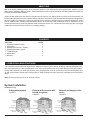
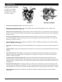
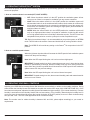
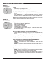
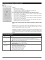
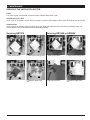
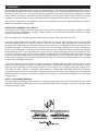
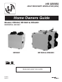
HR SERIES
HEAT RECOVERY VENTILATOR (HRV)
Home Owners Guide
Models HR100V, HR160H & HR220H
RESIDENTIAL USE ONLY
HR100V
HR160H & HR220H
READ AND SAVE THIS GUIDE
PP0924
09/2013
ABOUT S&P
S&P is the world's leading producer of air movement products. S&P manufactures and supplies fans, dampers, louvers
and recovery ventilators (ERVs & HRVs). These products are used in various industries including residential, commercial,
industrial and institutional buildings.
At S&P we take pride in the fact that our customers receive only the very highest levels of customer service and care. Our
internal and external technical and customer service teams are on-hand to provide professional and experienced application
advice to enable our customers to apply our products to their particular ventilation and air movement applications. As the
USA & Canada sales, marketing and distribution division of the Soler & Palau Ventilation Group of companies we are
committed to providing only the very highest levels of customer service. Our commitment in providing only the very highest
standards of customer service is key to our company strategy.
CONTENTS
SECTION
PAGE
1. Operation & Main Function . . . . . . . . . . . . . . 2
2. Description . . . . . . . . . . . . . . . . . . . . . . 3
3. Operating the Duotrol™ System . . . . . . . . . . . 4
4. Operating the Wall Controls . . . . . . . . . . . . . 4
5. Troubleshooting . . . . . . . . . . . . . . . . . . . 6
6. Maintenance . . . . . . . . . . . . . . . . . . . . . 7
7. Warranty . . . . . . . . . . . . . . . . . . . . . . . . 8
1. OPERATION & MAIN FUNCTIONS
Your ventilation system has been engineered & designed to improve your indoor air quality by reducing during the winter
time, excess humidity or other contaminants in your home and replacing this air by fresh filtered air from the outdoors.
During colder seasons, the units heat recovery core (polypropylene core) will reclaim the heat from the outgoing stale
air and use this heat to temper the incoming fresh air, which reduces the cost of effectively ventilating your home during
winter.
Note: Reverse process occurs in the summer months.
System Installation
(example only)
Independent system
FIGURE 1
Exhaust at the source with
forced air system
FIGURE 2
Page 2
Exhaust and supply in the
return
FIGURE 3
Bathroom
Control
Floor
Bathroom
Control
Floor
Bathroom
Control
Floor
Ground floor
Ground floor
Ground floor
Fresh air supply hood
Fresh air supply hood
Exhaust air hood
Basement
Exhaust air hood
Basement
HRV
Fresh air supply hood
HRV
Forced air
system
Exhaust air hood
Basement
HRV
Forced air
system
2. DESCRIPTION
VENTILATION SYSTEM
A. Fresh air from outside
B. Exhaust air to outside
C. Exhaust air from home
D. Fresh air to home
B
A
C
D
C
A
D
B
HR100V
HR160H & HR220H
•
Fresh Air from Outside Port (A): Inlet for fresh outdoor air.
•
Exhaust Air to Outside Port (B): Outlet for exhausting stale, humid & contaminated air to the outdoors after
transferring its heat to the recovery core.
•
Exhaust Air From Home Port (C): Exhausts stale, humid & contaminated air to the outside from multiple location of
the home or from the return air of the forced air system, prior to passing threw the heat recovery core. Ex: Bathroom,
laundry room etc.
•
Fresh Air to Home Port (D): Introduces & distributes clean & fresh air to your home. The homes fresh air ports
are normally installed in the main living areas or in the return/supply duct of the forced air system. Ex: Living room,
bedrooms, recreation rooms etc.
•
DuotrolTM Systems: Selects your ventilation modes (OFF, CONT or INTER), also to adjust your continuous airflow
rates: Increasing (+)/Decreasing (-).
•
Motors(2): Designed with high performance and reliability, they are maintenance free for your comfort and peace of
mind.
•
Synthetic Filters: Capture the largest particle & protects your heat recovery core from potential obstruction by these
particles.
•
Heat Recovery Core: A polypropylene cross-flow type it is designed to transfer the heat between both exhaust &
supply air streams without allowing any contamination or mixing of both air streams to maximize the efficient and
improve your indoor air quality.
•
Condensate Drain Pan & Drainage Hose: Captures the water that accumulates during the heat transfer and
defrosts sequence in the fall, winter & early spring seasons. Drain hose is connected to the drain pan and serves as
drainage for the accumulation of water. It is normal during summer months to find no condensation in drain pan or in
drainage hose.
•
Automatic Defrost Sequence: The defrost sequence is electronically controlled to measure the incoming outdoor
air temperature, the sequence is activated at -5°C (23°F) and colder and the duration is for 5 minutes then returns to
normal operation for 25 minutes. This system eliminates that the heat recovery core doesn’t build with ice or freezes.
•
Defrost sequence: Supply fans shuts down, the exhaust fan speed increases pending the measured outside
temperature.
Page 3
3. OPERATING THE DUOTROLTM SYSTEM
Our DuotrolTM System is state of the art technology simplified for quick and easy operation. The Duotrol™ System
serves two purposes:
1. Acts as a mode selector in run mode (OFF, CONT & INTER)
•
•
•
OFF: When the selector switch is in the OFF position the ventilation system will not
come on even if there’s a request for ventilation from any remote controllers.
CONT: When the selector switch is in the CONT position the ventilation system will
exhaust stale indoor air to the outside and will introduce fresh outdoor air continuously
on low speed except when there is a request for ventilation by one of the remote controllers then the ventilation system will exchange at high speed. (Recommended for
maximum indoor air quality.)
INTER: When the selector switch is in the INTER position the ventilation system will
only run on high speed when there is a request for ventilation. At this time the unit will
run on high speed until the level of humidity is below the set point, The HRT-3 timer has
completed its time period or once the cycles per hour has completed its cycle.
TIP: During hot and humid days, it is recommended that you put the system on INTERM
mode. This will reduce the amount of warm and humid fresh air coming inside the house.
Note: The HRRD-3P will override any setting on the DuotrolTM all except when in the OFF
position.
2. Acts as a variable speed selector
When the (+) button is pushed this will increase the CONT speed of both ventilation system
motors from the previous settings.
Note: When the LED stops blinking the unit is at its maximum high speed.
IMPORTANT: If speed setting is too high, extreme dryness can occur in home during winter
months. If speed setting is too high, extreme humidity levels can occur during hot humid
days. When the (-) button is pushed this will decrease the CONT speed of both ventilation
system motors from the previous settings.
Note: When the LED stops blinking the unit is at its minimum low speed.
IMPORTANT: If speed setting is too low, above normal humidity, stale and contaminated air
levels can occur in home.
4. OPERATING YOUR WALL CONTROLS
Adjusting your HRRD Series Humidity Sensor Dial should be set accordingly or relative to the outside conditions. During
winter season the Humidity Sensor Dial should be set within the comfort zone range (60% COMFORT ZONE 30%). If the
home has excess dryness, adjust the Humidity Sensor Dial towards the higher settings. (Turn counter clockwise). If excess
humidity is encounter turn the Humidity Sensor Dial to a lower setting. (Turn clockwise). Determining the humidity level in
your home (turn the round humidity sensor dial counter clockwise to the OFF position, then turn it back clockwise slowly
until you hear “click”. The click is the approximate level of relative humidity.
Note: The comfort zone for relative humidity is between 60% and 30%; please adjust accordingly to your needs or
requirements.
Page 4
4. OPERATING YOUR WALL CONTROLS (CONT)
HRRD-1
DEHUMIDISTAT
Features
• Dehumidistat to select the humidity level
• Comes complete with Relative Humidity Sensor Dial.
• Compatible with HR100V, HR160H and HR220H
RELATIVE HUMIDITY SENSOR DIAL (OFF/60%/COMFORT ZONE/30%):
• Overrides the ventilation system to high speed once the level of humidity is above the
set point.
• If the ventilation system is in CONT or INTERM mode the ventilation system will
automatically return to its original mode once the level of humidity is below the set point.
HRRD-3P
Note: By turning the relative humidity Sensor Dial to the OFF position does not turn off the
ventilation system. It only deactivates the relative humidity sensor.
DEHUMIDISTAT
Features
• Dehumidistat to select the humidity level
• Speed Control (OFF, NORMAL and REDUCED)
• Mode Control (INTERM and CONT)
• Green LED light on = OVERRIDE
• Orange LED light on = CONT/INTERM
• Comes complete with Relative Humidity Sensor Dial, Speed Control Selector Switch
and Mode Selector Switch.
• Compatible with HR100V, HR160H and HR220H
RELATIVE HUMIDITY SENSOR DIAL (OFF/60%/COMFORT ZONE/30%):
• Overrides the ventilation system to high speed once the level of humidity is above the
set point.
• If the ventilation system is in CONT or INTERM mode the ventilation system will
automatically return to its original mode once the level of humidity is below the set point.
Note: By turning the relative humidity Sensor Dial to the OFF position does not turn off the
ventilation system. It only deactivates the relative humidity sensor.
VENTILATION REDUCTION SELECTOR SWITCH (OFF/NORMAL/REDUCED):
• OFF – Sends command to turn off the ventilation system.
• NORMAL – The ventilation system operates on installers set speeds (CONT and
OVERRIDE)
• REDUCE – The ventilation system operates at 30% reduction in CONT and 15% in
OVERRIDE set speed
Note: Reduce mode will not decrease below the maximum low speed of the ventilation
system.
MODE SELECTOR SWITCH (INTERM/CONT):
• INTERM – Ventilation is halted meaning, automatically stopping and starting at intervals
the ventilation system from a command from a remote wall controls.
• CONT – Provides a continuous ventilation rate. The ventilation system will increase to
high from command of remote wall controls. (Recommended for maximum indoor air
quality.)
Page 5
4. OPERATING YOUR WALL CONTROLS (CONT)
HRT-3
PUSH BUTTON TIMER
Features
• 20/40/60 minutes exchange
• Green LED light on = OVERRIDE
• Comes complete soft touch button and integrated LED indicator light.
• Compatible with HR100V, HR160H and HR220H
HRT-3 PUSH BUTTON TIMER (20/40/60 MINUTES HIGH SPEED EXCHANGE)
• Press the button once the LED comes on then release, this activates the ventilation
system to high speed for 20 minutes.
• Press the button until the LED blinks 2 times then release, this activates the ventilation
system to high speed for 40 minutes.
• Press the button until the LED blinks 3 times then release, this activates the ventilation
system to high speed for 60 minutes.
• To turn off press button once, this will deactivate HRT-3 push button time and your
ventilation system will return to previous settings.
TIPS: The HRT-3 model push button timer allows the homeowner control of the indoor
humidity level in room were excess humidity is produced (Ex: Bathroom, kitchen & laundry
room).
TIPS: Always leave a small gap when closing curtains and blinds in the winter months, this
will allow proper circulation and will reduce or eliminate condensation that occurs when
warm air is trapped between window, curtains & blinds.
CAUTION: IT IS POSSIBLE (AND NORMAL) TO EXPERIENCE CONDENSATION ON YOUR
WINDOWS WHEN DRASTIC CHANGES IN INDOOR OR OUTDOOR TEMPERATURES
OCCUR, WHEN EXCESS HUMIDITY IS CREATED OR UPON CLOSING CURTAINS AND
BLINDS.
5. TROUBLESHOOTING
Problem
Solution
HRV not running
•
•
•
•
Verify breaker in electrical box.
Verify that dehumidistat or switch on HRV are activated to supply power to unit.
Unplug HRV, verify if controller is wired correctly to the connection box on the side of the
unit.
Verify low voltage box (DuotrolTM) on the unit.
Air too dry
•
•
•
Increase humidity level on the dehumidistat.
Switch ventilation mode from CONT to INTERM.
Install a humidifier.
Air too humid
•
•
•
•
Reduce the humidity level on the controller.
Verify if dryer is venting in basement.
Verify if heating wood is stored in basement.
Wait for outside temperature to change.
Ex. Summer can be extremely humid.
Verify balancing of the HRV or ERV.
•
Page 6
6. MAINTENANCE
SERVICING THE VENTILATION SYSTEM
Filters
Four times a year or as needed, vacuum the filters. Replace filters once a year.
Heat Recovery Core Unit
Once a year or as needed, vacuum the four surfaces, let soak in warm water for three hours, then spray rinse and let dry.
Inside the Unit
Once a year or as needed, clean the interior of the unit (walls and drain pan) with a mild and non abrasive soap. It is
recommended to use products that are environmentally-friendly.
Servicing HR100V
Servicing HR160H or HR220H
1. Slide out the filters.
2. Slide out the energy core.
1. Slide out the filters.
2. Slide out the energy core.
3. Vacuum the filters.
4. Wash the walls of the
unit.
3. Vacuum the filters.
4. Wash the walls of the
unit.
Page 7
7. WARRANTY
WARRANTY
S&P warrants the polypropylene heat recovery core against defects in material and workmanship for a lifetime from the
date of original installation; and all other components to be free from defects in material and workmanship for five (5) years.
Any units or parts which prove to be defective and are reported during the warranty period will be replaced at our option
when returned to our factory, transportation prepaid. Deterioration or wear by heat, abrasive action, chemicals, improper
installation or operation or lack of normal maintenance shall not constitute defects, and are not covered by warranty.
S&P will not be responsible for any installation, removal or re-installation costs or any consequential damage resulting in
failure to meet conditions of any warranty.
LIMITATION OF WARRANTY AND LIABILITY
This warranty does not apply to any such S&P product or parts which have failed as a result of faulty installation or abuse,
or incorrect electrical connections or alterations, made by others, or use under abnormal operating conditions or misapplication of the products and parts.
S&P will not approve for payment any repairs made outside the factory without prior written consent.
The foregoing shall constitute our sole and exclusive warranty and our sole and exclusive liability and is in lieu of all other
warranties, whether written, oral, implied or statutory. There are no warranties which extend beyond the description of
the page hereof. Seller does not warrant that said goods and articles are of merchantable quality or that they are fit for
any particular purpose. The liability of seller on any claim of any kind, including negligence, for any loss or damage arising out of or connected with, or resulting from the sale and purchase of the products and parts covered by this proposal,
acknowledgement, order or from the performance or breach of any contract pertaining to such sale or purchase, or from
the design, manufacture, sale, delivery, resale, installation, technical direction of installation, inspection, repair, operation
or use of any products or parts covered by this proposal, acknowledgement, order or furnished by seller shall, in no case
exceed the price allocable to the products or parts thereof which give rise to the claim and shall terminate one (1) year after
the shipment of said products and parts.
In no event, whether as a result of breach of contract, or warranty or alleged negligence, defects, incorrect advice or other
causes, shall seller be liable for special or consequential damages, including, but not limited to, loss of profits or revenue,
loss of use of the equipment or any associated equipment, cost of capital, cost of substitute equipment, facilities or services, down time costs, or claims of customers of the purchaser for such damages. S&P neither assumes nor authorizes
any persons to assume for it any other liability in connection with the sale of its fan products and parts. Some states do not
allow the exclusion or limitation of incidental or consequential damages, so all of the above limitations or exclusions may
not apply to you.
SAFETY ACCESSORIES WARNING:
The responsibility for providing safety accessories for equipment supplied by S&P is that of the installer and user of this
equipment. S&P sells its equipment with and without safety accessories, and accordingly it can supply such safety accessories upon receipt of order.