1
Ice Tube Clock Kit
Created by lady ada
Last updated on 2015-02-28 04:30:07 AM EST
Guide Contents
Guide Contents
Overview
2
4
Ice Tube!
Props!
Before you start...
4
5
5
FAQ
Design
6
8
Overview
5V Power Supply
3V Battery Backup Supply
High Voltage Boost Supply
VFD Tube
VFD Driver
Microcontroller
Make It!
8
8
8
9
13
14
15
17
Before you start!
17
Preparation
18
Prep
Tools
18
18
Parts List
23
Enclosure Parts
27
Board Assembly
29
How to succeed with your clock
Case Assembly
Use It!
70
76
User Manual
76
Daily Use
77
Using the clock on a daily basis
Power Supplies
12hr vs 24hr mode
Displaying the day and date
Turning on/off the alarm
Snoozing
Set Alarm
77
77
77
78
78
79
80
Introduction
© Adafruit Industries
29
80
https://learn.adafruit.com/ice-tube-clock-kit
Page 2 of 107
Setting the region
80
Set Time
82
Introduction
Setting the time - 12 hr mode
Setting the time - 24 hr mode
Set Date
82
82
83
85
Introduction
Setting the date - USA mode
Setting the date - European mode
Set Volume
85
85
86
88
Introduction
Changing the Volume
88
88
Set Brightness
90
Introduction
How to set the brightness
90
90
Set Region
92
Introduction
Setting the region
92
92
Mods
94
Installing Mods
GPS Timekeeping
94
94
Downloads
106
Hardware
Firmware
Datasheets
106
106
106
Support Forums
© Adafruit Industries
107
https://learn.adafruit.com/ice-tube-clock-kit
Page 3 of 107
Overview
Ice Tube!
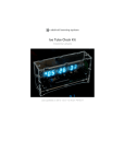
This is our first clock kit design, made with a retro Russian display tube!
Cool glowing blue tube with 8 digits and alarm on/off dot
Adjustable brightness
Alarm with volume adjust
Precision watch crystal keeps time with under 20ppm (0.002%) error (< 2 seconds a day) - its
not an atomic clock but it will wake you up in time each morning
Clear plastic enclosure protects clock from you and you from clock
Battery backup will let the clock keep the time for up to 2 weeks without power
Selectable 12h or 24h display
Displays day and date
10 minute snooze
Integrated boost converter so it can run off of standard DC wall adapters, works in any
country regardless of mains power
Great for desk or night table use, the clock measures 4.9" x 2.9" x 1.3" (12.5cm x 7.4cm x
3.3cm)
© Adafruit Industries
https://learn.adafruit.com/ice-tube-clock-kit
Page 4 of 107
Completely open source hardware and software, ready to be hacked and modded!
There is also a design document describing the hardware (http://adafru.it/clB), which is worth
checking out as there are a few cool hacks involved in this design. One is an onboard open-loop
boost converter that uses a microcontroller PWM pin to generate 60VDC to light the tube. Another is
code for a microcontroller-only low-power RTC that runs at only 50uA without the need of an
external RTC chip.
Props!
Thanks to Riad for his excellent documentation on the inGrid clock (http://adafru.it/c19), and w0z for
designing a beautiful enclosure using only graph paper and a pair of calipers (http://adafru.it/c1a).
Before you start...
This kit generates a high voltage - 40V to 70VDC. Only persons who are competent at electronics
assembly and understand the dangers of high voltages may attempt to assemble this kit! Safe
assembly and operation of this kit is the users responsibility.
This information is provided 'as is'. No responsibility is accepted for any damage, injury or death as
a result of assembling this kit or using the information therein.
The assembled unit must be properly enclosed to prevent contact with high voltages and kept out of
reach of children. Keep this kit away from water and other damp environs.
As with any self-assembled electronics project improper assembly could cause damage to the kit,
overloading of a circuit or an electrical fire:
See A Factsheet on Home Electrical Fire Prevention (http://adafru.it/c1b).
If you don't feel comfortable in assembling the kit or using the clock, please contact us to return it for
a full refund.
© Adafruit Industries
https://learn.adafruit.com/ice-tube-clock-kit
Page 5 of 107
FAQ
My clock is 'spazzing' - resets constantly
Check C10 and the two resistors next to it.
Can I add a 'radio atomic time' module to this clock?
You can try but you will almost certainly not succeed, the multiplexing display and boost
converter generate too much noise. If the module was 10 feet away it may work.
Can I add a GPS module to this clock?
Yes, we have a tutorial with our suggested method and some code (http://adafru.it/clB).
What is the lifetime of the tube?
The life should be 10+ years. Keeping the display dim will likely extend the life. The tube will
slowly get dimmer as the phosphor degrades. The tubes are 'new old stock' from around the mid
90's.
The clock is blinking once a second, is it broken?
You have to set the time, once the time is set the clock will stop blinking.
The clock 'works' but does not display the time, however the menus work.
Your crystal/capacitors are not installed properly.
The clock 'works' for some time but then stops keeping time.
Your crystal/capacitors are not installed properly.
The clock 'works', but it's -really- inconsistant at keeping time.
Your crystal/capacitors are not installed properly
How can I program the chip/firmware?
You will need a programmer such as an AVR-ISP or USBtinyISP (http://adafru.it/cla).
You may also have to remove the tube to program it (we had to with the USBtinyISP). If you're
using a USBtiny, jumper the 1.5k output resistors (check the usbtiny docs for information on how
to do this). We dont guarantee that you can program the clock in-circuit so experimentation is
key!
My tube isn't blue!
Some tubes may appear more cyan than blue. The apparent color of the tube changes with
background, lighting, and brightness.
At low brightness, the seconds are dimmer than hours.
Unfortunately this is an effect of the way we drive the tube. It is not apparent at medium and high
brightness.
© Adafruit Industries
https://learn.adafruit.com/ice-tube-clock-kit
Page 6 of 107
© Adafruit Industries
https://learn.adafruit.com/ice-tube-clock-kit
Page 7 of 107
Design
Overview
This clock took a long time to get right! However, there's enough interesting stuff going on in the
circuitry that its worth explaining how some of the decisions were made and why they work.
This tutorial was written for a slightly older version, there are some minor differences, the
differences do not affect the overall functionality.
5V Power Supply
The first part of the circuit is the 5V power supply. This is a generic 7805 style circuit.
There is a 2.1mm jack J1for center-positive ~9VDC power supplies. D1 is a protection diode, in the
kit this is a schottky to avoid mixups but a 1N4001 is fine too. C1 and C2 provide input noise
filtration. The input voltage is called 9V but it can range from 7V to 16V depending on the wall wart
used.
The regulator is a classic 7805, TO-220 style. On the board layout, we use the ground plane as a
basic heatsink. This part passes about 150mA and it gets a little hot.
D2 is another diode, this one is used to prevent the tiny coin cell from back-powering the 7805
which has huge quiescent current (like 2mA). We use a schottkey so that the voltage drop is about
0.2V. C3 andC4 are output noise filtration caps.
3V Battery Backup Supply
© Adafruit Industries
https://learn.adafruit.com/ice-tube-clock-kit
Page 8 of 107
3V Battery Backup Supply
The battery backup is a 12mm lithium coin cells. These cells provide about 3V which is great for
running a microcontroller (1.5v is too low). 12mm was used because it was small enough to fit on
the PCB but still had enough juice to run the clock (minus display) for a couple of weeks. D4 is used
to prevent the 5V supply from 'charging' the 3V battery, thus destroying it.
High Voltage Boost Supply
Tubes such as VFDs, Nixies, Decatrons, etc require high voltage to light the gas in the tube. For
nixies, this iabout 170VDC. VFDs aren't as bad they only need about 30-50VDC. In order to reduce
cost, we use the microconrtoller to make a boost converter and avoid paying $5 for a seperate chip.
We can do this because we don't need a precision output and the current draw is mostly constant.
The boost regulator is run open-loop there is no feedback resistor divider as it isn't necessary as
long as the input voltage is within a reasonable range.
The boost circuit works by connecting the power inductor L1 to ground that current can flow through
it by turning on Q2. After a little bit of time, we disconnect the from ground (by turning off Q2) this
means that there is no longer a path for the current in L1 to flow to ground. When this happens, the
© Adafruit Industries
https://learn.adafruit.com/ice-tube-clock-kit
Page 9 of 107
voltage across the inductor increases (this is the electric property of inductors) and charges up C6 .
When the voltage increases to the level we want it to be (30V+) we turn on Q2 again which allows
the current in L1 to flow back to ground. If we do this fast enough, and C6 large enough, the voltage
on C6 is smoothed out and we get a nice steady high voltage.
The timing of turning off/on Q2 allows us to modify the output voltage. Normally there is a feedback
resistor to the microcontroller but it is not here because we are running it open-loop. To drive Q2 we
use the PWM output from the microcontroller and adjust the duty cycle to vary brightness.
The voltage in is nominally 9 to 12VDC
The current draw for the IV-18 tubes is about 8mA per digit and 11mA for the grid.
Remember, though, that we only light up one digit at a time! So we need about 20mA total
(we also meaured this in-circuit to verify)
The voltage output is going to be between 30V-50V (its really much too bright after that point)
The PWM output speed of the microcontroller is F_CPU / 256 = 8 MHz / 256 = 31.25KHz
(period of 32 useconds)
With this information we can calculate the inductor size and capacity!
The optimal transfer between Vin and Vout is:
Vo/Vi = 1 / (1-D) where D is the duty cycle.
Solving for D = 1 - (Vi/Vo) and plugging in numbers:
For Vo = 50V and Vi = 9V, D = 82% (maximum)
For Vo = 30V and Vi = 12V D = 60% (minimum)
So the duty range will be between 60% and 82%. That would correspond to between ~150 and 220
out of 256, but note that when the PWM signal is low the switch is on so we need to invert that to a
range of about 36 to 106 (in the code we actually use about 20 to 90).
OK so our PWM range is good, we just want to keep it between around 10% and 90% which we do.
Next, we need to make sure that the inductor continuously dumps current into C6 the entire time Q2
is off (continuous conduction mode). This is dependant on a lot of variables:
D*T*Vin/(2*L) < iout/(1-D)
Note that T is period time and is = 1/frequency. Solving for L, we choose the lowest duty cycle which
will give us the upper bound for the inductor:
D*Vin * (1-D) / (freq * 2 * Iout ) < L
© Adafruit Industries
https://learn.adafruit.com/ice-tube-clock-kit
Page 10 of 107
D = 60% (0.6)
iout = 20mA (0.02 Amp)
Vin = 12V nominal
1/T = freq = 31250 HzL > 0.6 * 12 * (1 - 0.6) / (31250* 2 * 0.02)
L > 2304 uH
This is our upper limit, so lets just say L = 2200uH (a standard value). Note that for 9V->60 we need
L > 918uH which is our lower bound and our average case is a duty cycle of about 70% which is
1500uH.
We also want to make sure that we have a enough current capacity, so lets calculate the maximum
current that builds up in the inductor. We now have to pick this for the -smallest- inductor, in the
case of 9V boosting to 50V, an 82% duty cycle.
Ipk = (Vin * D)/(f * L)
Ipk = (9 * 0.82)/(31250 * .001) = 0.24 Amp
So! We want to make sure our inductor is > 2200 uH and will not saturate below 0.24 A.
The important thing to note here is that, for a given package (size) of inductor, the higher the
inductance the lower the current capability.
Since this is a through-hole kit, we have to stick with a radial/axial inductor.
© Adafruit Industries
https://learn.adafruit.com/ice-tube-clock-kit
Page 11 of 107
Searching Mouser for power inductors, we find the RLB9012 family (datasheet (http://adafru.it/c1d))
which is the same type used in the mintyboost. This is a good inductor family, lets check out the
range.
It looks like we're good to go with this group of inductors as the max current capacity of the 2200uH
is well above our minimum 0.25 Any value higher than that will be OK as the Ipk will fall faster than
the IDCmax
In reality, you don't need such high inductances because our system is not running on a battery and
doesn't require a great power supply with low ripple and good efficiency. Inducances 270uH and
lower worked just fine, the converter is operating in discontinuous mode which is not as efficient. Its
also not as easy to calculate the precise specifications. Luckily this is a very indiscriminate tube and
is cool with ripple and voltage fluctuations.
© Adafruit Industries
https://learn.adafruit.com/ice-tube-clock-kit
Page 12 of 107
The diode is a schottky type, and needs to have a breakdown voltage larger than the maximum
boost voltage (in this case 60V) we're using MBR160 (http://adafru.it/c1e) with 60V breakdown.
One way to improve the design to reduce the size and power requirements of the inductor is to
increase the frequency. Doubling the frequency halves the required inductance and current
requirements of the inductor!
I have a nice little calculator if you want to design your own basic boost
converter (http://adafru.it/clD)
Thanks tons to Riad at jfet.org for the idea and calculations! (http://adafru.it/c19) (He has some
great clock designs, so check them out)
For more information on boost converters see this article on wikipedia. (http://adafru.it/c1g)
VFD Tube
The VFD tube is the display for the clock. It has 9 digits, 8 of which are standard 7 segment plus dot
displays. The leftmost digital has only a * and -. Instead of having 60+ connections for each
segment, the display is gridded out so that you can only turn on one digit at a time (1-9) with the
selected segments (A-H). The microcontroller sweeps through all of the digits in order at >100Hz so
that it appears as if they are all lit up at once.
The segment lines are to be powered with 30-60VDC only. There is also a ground connection and a
VBias pin, which is used for the display filament. In theory the filament should be driven with a 60Hz
AC supply but DC is acceptable in this case.
© Adafruit Industries
https://learn.adafruit.com/ice-tube-clock-kit
Page 13 of 107
For more information on driving VFDs, see Noritake's guide (http://adafru.it/c1h)
VFD Driver
Because the VFD runs at high voltages, a microcontroller cant drive them directly. We could use
high voltage transistors and use those as buffers but that would take a lot of space so instead we
use a VFD controller chip, this one in particular is called the MAX6921 (http://adafru.it/c1i). Its quite
nice in that you can control it with only 3 or 4 lines (SPI protocol). The output pins of the driver go to
the header which is connected to the VFD.
There is also a PNP transistor that we use to turn off both the filament DC bias voltage and the
power to the driver. This saves power when the clock is in sleep mode.
© Adafruit Industries
https://learn.adafruit.com/ice-tube-clock-kit
Page 14 of 107
For more information check out the MAX6921 datasheet (http://adafru.it/c1i)
Microcontroller
Finally we get to the brains of the project, an AVR microcontroller. This one in particular is the
ATmega168V or 168P. The V or P designation means it can run at 1.8V voltages, otherwise the chip
requires 4V or more to run and that is more than the battery backup voltage
ISP is the In-circuit Serial Programming header, it is a standard 6-pin male header in the standard
layout for AVR programmers
Since this project is a clock, it needs to tell time accurately. Q1, C8 and C9 are the 32.768KHz clock
crystal that allows the chip to keep time. The internal oscillator is not nearly precise enough and
external resonators or crystals are better but still not as good. 32.768KHz has a nice property that it
oscillates 2^15 times per second which makes the timer math easy. Q1 should have 12.5 pF load
capacitance. C8/C9 are chosen to match this capacitance and are equal to approximately 2* the
load capacitance. The reason they are 22pF and not 25pF is that there is 3pF capacitance just for
the chip, PCB and socket. With proper matching, the clock should keep time to 0.002 % accuracy or
better - about 2 seconds a day.
There are some interface buttons S1, S2 and S3 these are for setting the clock and displaying the
date. SW1 is a SPDT right-angle slide switch which turns the alarm on and off. There are no
© Adafruit Industries
https://learn.adafruit.com/ice-tube-clock-kit
Page 15 of 107
external pull-ups because we are using the ones internal to the AVR.
There is also a piezo buzzer SPK, used for the alarm function. There are two pins used on either
side. For low volume, one pin is connected to ground and the other pin oscillates to create a 5 Vpp
squarewave. For high volume, the first pin is made to oscillate opposite from the second, this
creates the appearance of a 10 Vpp square wave which is much louder!
R1 and R2 are a resistor divider that allows the microcontroller to be alerted when the DC adapter
loses power. If the power supply is at 4.5V or higher, then the voltage at the input pin is
Vpin = Vsupply * R2 / (R1+R2)
4.5V * 100/(100+270) = 1.22V
Which means that, at worst, the voltage is 1.22V
When the power dies, and goes to battery backup, the voltage is about:
3V * 100/(100+270) = 0.8V
The input pin on the microcontroller is connected to the analog comparator. The other side of the
comparator is connected to the internal band-gap reference, a voltage that is the same no matter
what the power supply is at. According to the datasheet, the bandgap is at 1.1V and at most is 1.2V.
When the input voltage drops below this reference of 1.1V (which corresponds to 4VDC), the
microcontroller receives an interrupt immediately indicating that the power died. Because the
microcontroller is extremely fast, it can go into sleep mode within 100 cycles (12.5 microseconds).
The faster it goes into sleep mode the less power is consumed so this is much faster than checking
an ADC pin every second. C10 is just there to stabilize the divider and prevent power spikes from
turning the clock off.
R4 and the two pads CT1 and CT2 are not used in general and are basically intended for hacks and
mods, adding sensors or using the clock to trigger an output.
© Adafruit Industries
https://learn.adafruit.com/ice-tube-clock-kit
Page 16 of 107
Make It!
Before you start!
This kit generates a high voltage - 40V to 70VDC. Only persons who are competent at electronics
assembly and understand the dangers of high voltages may attempt to assemble this kit! Safe
assembly and operation of this kit is the users responsibility.
This information is provided 'as is'. No responsibility is accepted for any damage, injury or death as
a result of assembling this kit or using the information therein..
The assembled unit must be properly enclosed to prevent contact with high voltages and kept out of
reach of children. Keep this kit away from water and other damp environs.
As with any self-assembled electronics project improper assembly could cause damage to the kit,
overloading of a circuit or an electrical fire. :
See A Factsheet on Home Electrical Fire Prevention (http://adafru.it/c1b).
If you don't feel comfortable in assembling the kit or using the clock, please contact us to return it for
a full refund.
© Adafruit Industries
https://learn.adafruit.com/ice-tube-clock-kit
Page 17 of 107
Preparation
Prep
Learn how to solder with tons of tutorials (http://adafru.it/aTk)!
Don't forget to learn how to use your multimeter too (http://adafru.it/aOy)!
Tools
There are a few tools that are required for assembly. None of these tools are included. If you don't
have them, now would be a good time to borrow or purchase them. They are very very handy
whenever assembling/fixing/modifying electronic devices! I provide links to buy them, but of course,
you should get them where ever is most convenient/inexpensive. Many of these parts are available
in a place like Radio Shack or other (higher quality) DIY electronics stores.
Soldering iron
Any entry level 'all-in-one' soldering iron that you
might find at your local hardware store should
work. As with most things in life, you get what you
pay for.
Upgrading to a higher end soldering iron setup, like
theHakko FX-888 that we stock in our
store (http://adafru.it/180), will make soldering fun
and easy.
Do not use a "ColdHeat" soldering iron! They are
not suitable for delicate electronics work and can
damage the kit (see here (http://adafru.it/aOo)).
Click here to buy our entry level adjustable 30W
110V soldering iron. (http://adafru.it/180)
Click here to upgrade to a Genuine Hakko FX-888
adjustable temperature soldering
iron. (http://adafru.it/303)
© Adafruit Industries
https://learn.adafruit.com/ice-tube-clock-kit
Page 18 of 107
Solder
You will want rosin core, 60/40 solder. Good solder
is a good thing. Bad solder leads to bridging and
cold solder joints which can be tough to find.
Click here to buy a spool of leaded solder
(recommended for beginners). (http://adafru.it/145)
Click here to buy a spool of lead-free
solder. (http://adafru.it/734)
Multimeter
You will need a good quality basic multimeter that
can measure voltage and continuity.
Click here to buy a basic
multimeter. (http://adafru.it/71)
Click here to buy a top of the line
multimeter. (http://adafru.it/308)
Click here to buy a pocket
multimeter. (http://adafru.it/850)
© Adafruit Industries
https://learn.adafruit.com/ice-tube-clock-kit
Page 19 of 107
Flush Diagonal Cutters
© Adafruit Industries
https://learn.adafruit.com/ice-tube-clock-kit
Page 20 of 107
You will need flush diagonal cutters to trim the
wires and leads off of components once you have
soldered them in place.
Click here to buy our favorite
cutters. (http://adafru.it/152)
Solder Sucker
Strangely enough, that's the technical term for this
desoldering vacuum tool. Useful in cleaning up
mistakes, every electrical engineer has one of
these on their desk.
Click here to buy a one. (http://adafru.it/148)
Helping Third Hand With Magnifier
Not absolutely necessary but will make things go
much much faster, and it will make soldering much
easier.
Pick one up here. (http://adafru.it/291)
© Adafruit Industries
https://learn.adafruit.com/ice-tube-clock-kit
Page 21 of 107
© Adafruit Industries
https://learn.adafruit.com/ice-tube-clock-kit
Page 22 of 107
Parts List
Check to make sure your kit comes with the following parts.Sometimes we make mistakes so double
check everything and email [email protected] if you need replacements!
Please note that R4 is not used, and is a 'breakout' for hacking purposes!
Image
Name
Description
IV-18 vacuum fluorescent
display (VFD) tube.
Tube
Part # & Datasheet
Qty
IV-18
It is normal for the tube to
Rare (check ebay and
have a black 'spot' on the
HAM fests!)
back and white 'paint' on
the back of the display.
IC1
Microcontroller
(preprogrammed with
firmware when
purchased in a kit).
IC2
VFD driver in PLCC-28
package.
ATmega168V-10PU
1
1
MAX6921
Maxim
1
5V regulator
IC3
Q1
© Adafruit Industries
7805 TO-220 package
32.768 KHz, 12.5 pF
watch crystal
Generic 7805
1
Generic 32.768KHz
crystal
1
https://learn.adafruit.com/ice-tube-clock-kit
Page 23 of 107
Q2
N-Channel HEXFET
Vishay IRFD110PBF
1
P-channel MOSFET
Q3
-- or --
Q3 has been replaced by
ZVP 3306 (older)
Q4 in newer kits.
These are Static
Sensitive Parts! Handle
with care!
Q4
ZVP2110A (newer)
1
D1, D2,
D3, D4
60V breakdown Schottky
Diode
MBR160
4
D5
60V zener diode
1N5264B
1
F1
200mA fuse
These look a lot like
capacitors but the leg
spacing is 0.2" not 0.1"
RXEF020
1
L1
2200uH power inductor,
>0.2A current capability
RLB9012-2200
1
Generic
1
1/4W 5% 10K resistor
R5
© Adafruit Industries
Brown, Black, Orange,
Gold
https://learn.adafruit.com/ice-tube-clock-kit
Page 24 of 107
1/4W 5% 270K resistor
R1
Generic
1
Generic
1
Generic
1
Generic
2
Generic
3
Generic
These look a lot like the
0.1uF caps but they have
a kink in the leads
1
Red Violet Yellow Gold
1/4W 5% 100K resistor
R2
Brown, Black, Yellow,
Gold
1/4W 5% 22 resistor
R3
Red Red Black Gold
20pF ceramic capacitor
C8, C9
These might also be
blue colored!
C1, C3,
C10
0.1uF ceramic capacitor
(104)
0.1uF ceramic
capacitor 100V
C5
Electrolytic capacitor
© Adafruit Industries
https://learn.adafruit.com/ice-tube-clock-kit
Page 25 of 107
Electrolytic capacitor
C6
22uF / 100V
(or higher)
Generic
1
Generic
2
Electrolytic capacitor
C2, C7
© Adafruit Industries
47uF / 25V
(or higher)
C4
220uF/6.3V capacitor
(or higher)
Generic
1
J1
2.1mm Power Jack
CUI PJ-202AH
1
IC2'
28-PLCC socket
Generic
1
IC1'
28-pin socket
Generic
1
ICSP
6 pin header, 0.1"x0.1"
spacing
Generic
1
SW1
Right angle SPDT switch
C&KOS102011MA1QN1 1
S1, S2,
S3
Right angle tactile switch
EVQ-PF008K
https://learn.adafruit.com/ice-tube-clock-kit
3
Page 26 of 107
JP1
2x10 position 0.1" x 0.1"
female header
Generic
1
JP2
2x10 position 0.1" x 0.1"
right angle header
Generic
1
SPK
Piezo Speaker
PS1240P02AT
1
BATT
12mm 3V lithium coin cell CR1220
1
BATT'
12mm coin cell holder
Keystone 3001
1
PCB
Paired circuit boards
Adafruit Industries
1
Enclosure Parts
© Adafruit Industries
https://learn.adafruit.com/ice-tube-clock-kit
Page 27 of 107
Description
Qty
Acrylic enclosure parts - 6 differently cut parts
6
Nylon 4-40 Hex nut
10
Nylon 4-40 1/2" machine screw
8
© Adafruit Industries
https://learn.adafruit.com/ice-tube-clock-kit
Page 28 of 107
Board Assembly
How to succeed with your clock
Go step by step, following the instructions and performing ALL the tests.
If one of the tests fails, DONT KEEP GOING! Stop, try to get the test working again and post
in the forums if you're stuck. If you keep going it will not magically fix itself and you'll have
much more to try to debug...
Get ready by checking all your parts against the Bill
of Materials (parts list). Once you are sure you
have everything, prepare your workspace by
heating up the soldering iron, wetting the sponge
and arranging your tools and parts so they will be
convenient.
The first part to be placed is the DC jack. This
connector allows you to power the clock using an
external power adapter.
Place the part as shown, it will only be able to fit in
one way.
Now flip the board over. If the DC jack doesn't stay
in place, you can use a piece of tape to hold it
against the PCB, or use a finger if you are
dexterous.
Now using your hot soldering iron, press the long
side of the tip against the one of the pins and pads
for the DC jack. Wait a few seconds until they are
heated up and then press solder into the
connection so that it flows into the entire pad.
Repeat for all three pads. Make sure there is plenty
of solder filling the holes completely, they provide
mechanical strength!
© Adafruit Industries
https://learn.adafruit.com/ice-tube-clock-kit
Page 29 of 107
The second part to go in the fuseF1. The fuse
looks suspiciously similar to a ceramic capacitor.
So before you continue lets identify the fuse.
The fuse, all the way on the left, is yellow and has a
larger 'head'. The leads have a kink in them and
the lead spacing is wider than the capacitors, 0.2"
© Adafruit Industries
https://learn.adafruit.com/ice-tube-clock-kit
Page 30 of 107
(5mm)
Once you have picked on the correct part, place
the fuse next to the jack. Remember it should just
fit, if you have to bend the leads a bunch you may
have picked out a capacitor. Fuses are just 'wires'
so they can go either way and work fine. The fuse
protects the circuit, when the circuit tries to draw
more than 200mA, the fuse heats up and cuts the
power to the circuit. After a whilewhen it cools
down, the fuse resets and passes current to the
clock again.
The fuse will sit 'above' the PCB when placed
correctly. This makes sure there is plenty of air
circulating around the part so dont try and squish it
against the PCB all the way
With the leads bent, the part will stay in place. Flip
the PCB over.
© Adafruit Industries
https://learn.adafruit.com/ice-tube-clock-kit
Page 31 of 107
Now using your soldering iron, heat up both the
pad and pin of the component and apply solder. Do
the same for the other leg.
© Adafruit Industries
https://learn.adafruit.com/ice-tube-clock-kit
Page 32 of 107
Next it is time to clip the extra long leads of the
fuse. Using your diagonal/flush cutters, clip the
wires right above where the solder joint tapers off.
Next is the input protection diodeD1 and D2.
Diodes are a semiconductor component that only
allows current to go one way. By placing a diode
between the power input and the circuitry, it helps
protect against plugging in a negative DC power
© Adafruit Industries
https://learn.adafruit.com/ice-tube-clock-kit
Page 33 of 107
supply (backwards) which would make the kit
release its 'magic smoke'. As you can imagine, its
important to place the component in the right way.
On one end of the diode is a white/silver stripe.
Make sure this stripe matches the stripe in the
silkscreen image. See the image left if you're not
certain.
Bend each diode into a 'staple' shape and once
you've double-checked the polarity, place the
diodes in the D1 and D2 spots. Then bend the
leads out a little so that the diode stays flat against
the PCB.
Now using your soldering iron, heat up both the
pad and pin of the component and apply solder. Do
the same for the other legs.
© Adafruit Industries
https://learn.adafruit.com/ice-tube-clock-kit
Page 34 of 107
Next it is time to clip the extra long leads of the
diode. Using your diagonal/flush cutters, clip the
wires right above where the solder joint tapers off.
© Adafruit Industries
https://learn.adafruit.com/ice-tube-clock-kit
Page 35 of 107
Next is the 7805 5V regulator chip IC3. This
component takes the voltage from the power
adapter, which can be from 7V to 16V, and reduces
(regulates) it dow to a nice smooth 5V. Bend the
legs into a 90deg angle...
And then lay the part down so it matches the
silkscreen. Try to get the hole in the regulator's
metal tab to line up with the hole in the PCB. you
can make this a little easier by taking a 4-40 screw
(such as those in the enclosure kit) and placing it
through both holes to line them up.
Then to keep it in place, solder one pin of the 7805
from the top.
© Adafruit Industries
https://learn.adafruit.com/ice-tube-clock-kit
Page 36 of 107
Once you have the 7805 tacked in place, flip over
the board and solder in the three pins.
And clip them short.
© Adafruit Industries
https://learn.adafruit.com/ice-tube-clock-kit
Page 37 of 107
Next is C2, the 47uF/25V electrolytic capacitor.
This capacitor smooths out any large ripples in
power coming into the kit. Electrolytic capacitors
arepolarized which means they must be placed
correctly or they wont work at all. If you look at the
capacitor you'll notice one leg is longer than the
other, this is the positive (+) lead. Make sure this
lead goes into the pad silkscreened with a +. See
left for how to place the capacitor.
Next is C4, a 220uF/6.3V electrolytic, which is the
capacitor which helps reduce noise on the
regulated 5V supply. It is electrolytic so make sure
its placed correctly.
© Adafruit Industries
https://learn.adafruit.com/ice-tube-clock-kit
Page 38 of 107
Once the electrolytic capacitors are placed
correctly, bend out the leads and solder them in
place.
Use the diagonal cutters to clip the leads short.
© Adafruit Industries
https://learn.adafruit.com/ice-tube-clock-kit
Page 39 of 107
Now place C1 and C3, both 0.1uF ceramic
capacitors. Make sure to use the 'plain' 0.1uF
capacitors. These don't have kinked leads (middle
in the lefthand photo).These capacitors are smaller
and work with C2and C4, smoothing out smaller
high frequency noise. Ceramic capacitors are not
polarized so you can put them in either way!
Bend the leads, solder and clip.
© Adafruit Industries
https://learn.adafruit.com/ice-tube-clock-kit
Page 40 of 107
Now is a good time to take a break and test your
work so far. Place the board down on a clean
surface - make sure there are no stray wires or
solder balls, etc.
Plug in a DC adapter that provides 7VDC-12VDC
and at least 200mA, positive tip. (See this tutorial
on how to verify your adapter (http://adafru.it/aZZ))
© Adafruit Industries
https://learn.adafruit.com/ice-tube-clock-kit
Page 41 of 107
Now find your handy multimeter, and set to
measure DC voltages (and set the range if
necessary).
Place the ground/black probe on the big silver tab
of the 7805 (which is a ground connection). Then
place the tip of the positive/red probe on the first
pin of the 7805 (closest to the 'bottom', as shown in
the image).
You should get a DC voltage between 7V and 13V.
If not, check: is the adapter plugged in? Are the
diodes correct? Is the multimeter hooked up right
and in the right range?
Now check the 5V regulator by probing the third pin
(closest to the 'top' in this image). You should get a
steady voltage between 4.7V and 5.2V DC
If the voltage is not right, check the components
such as the electrolyic capacitors, and IC3 now.
Make sure you have the 5V supply working now,
since it is an essential test!
Unplug the board as soon as you are done, do not
solder while the board is plugged in.
We will now continue and place the 270K resistor
R1, this resistor is part of the 'lost power' detection
circuitry. Resistors are nonpolarized so they can go
in 'either way'. Bend the part into a staple and
place it over the silkscreened R1.
Also place the piezo beeper SPK. This is the alarm
noise-maker! It is non-polarized and can go in
either way.
Solder in both components and clip the leads.
© Adafruit Industries
https://learn.adafruit.com/ice-tube-clock-kit
Page 42 of 107
© Adafruit Industries
https://learn.adafruit.com/ice-tube-clock-kit
Page 43 of 107
Now place the IC socket. The socket protects the
microcontroller chip and allows it to be replaced if
necessary.
The socket has a U-shaped notch in one end.
Make sure that this notch matches the U-shaped
notch in the silkscreen, see the image to the left if
you're not sure. If you end up putting the socket in
backwards, don't fret. Its not essential that it is in
right, but it will help you if you have to replace the
chip.
You can keep the socket in place with tape or if you
have long fingernails, by bending over two of the
little legs to hold it in place. First solder in 2
opposite corners. Then solder the rest of the pins.
They do not need to be clipped as they are already
quite short.
© Adafruit Industries
https://learn.adafruit.com/ice-tube-clock-kit
Page 44 of 107
Now it is time to insert the chip! Carefully remove it
from the packaging. You'll have to bend the pins in
a little to make them fit nicely into the socket. I grab
both ends and rock the pins against a tabletop.
(The image shows a smaller chip, but the idea is
the same). Once the legs are parallel, locate the Ushaped notch in one end. Make sure that this end
goes into the notched-end indicated on the
silkscreen (and, hopefully, the socket as well)
Double check the chip is in right!
Now making sure that all the legs are lined up, and
not bent or twisted, press the chip into the socket. It
should seat itself easily without a lot of force.
© Adafruit Industries
https://learn.adafruit.com/ice-tube-clock-kit
Page 45 of 107
Now we will do another quick test. Clear off the
table and plug in the board. You should hear the
piezo beep. If it does not, check the 5V regulator,
make sure the chip is in right, and that R1 is in the
correct location.
We'll now finish the low voltage power detection
circuit. Solder in the 100kohm resistor R2 (this
forms a resistor divider with R1) and 0.1uF
capacitor C10 which keeps the resistor divider
voltage steady.
Solder and clip the parts.
© Adafruit Industries
https://learn.adafruit.com/ice-tube-clock-kit
Page 46 of 107
Solder in the 10K resistor R5. Photos to come
soon. This resistor is next to R1 and R2 you just
placed. Bend the 10K resistor over, as shown in the
image to the left, and solder in place.
© Adafruit Industries
https://learn.adafruit.com/ice-tube-clock-kit
Page 47 of 107
Now we will place the 32.768 khz clock crystal. This
crystal lets the chip keep time properly. The crystal
Q1 is a silver tube and is symmetric so it can go in
either way. Next to it goes two 20pF capacitors C8
and C9. These caps stabilize the crystal to keep
the timing correct. They are ceramic capacitors but
are in a disc package. They are symmetric and can
go in either way.
Solder and clip the parts.
Please note that a few people have had clock
difficulties because they put the 20pF
capacitors in wrong. They'll fit if rotated 90
degrees so DOUBLE CHECK that the caps are
in right!
The 20pF capacitors might also be blue
colored instead of orange!
Now we will begin to build the boost converter that
generates the 60V for the VFD tube.
Place 47uF/25V capacitor C7Make sure to place it
correctly as it is a polarized capacitor.
© Adafruit Industries
https://learn.adafruit.com/ice-tube-clock-kit
Page 48 of 107
We also need to place the high voltage transistor
that does the switching in the switching regulator.
Its a little confusing how to place it because there is
no notch. However, two of the pins are bridged.
These go on the right as shown.
Place the transistor chip solidly against the PCB.
© Adafruit Industries
https://learn.adafruit.com/ice-tube-clock-kit
Page 49 of 107
Next place another Schottky diode D3 as shown,
make sure the stripe lines up properly.
Also place the large 100V capacitor C6 (its the
large round thing) which smooths the output of the
boost converter. Make sure to place it correctly as
it is a polarized capacitor.
Next is the inductor L1 which stores and releases
power to boost the voltage up. Inductors are just
coils of wire so they are not polarized and can go in
either way.
© Adafruit Industries
https://learn.adafruit.com/ice-tube-clock-kit
Page 50 of 107
Solder in all of the components.
The diode connects directly to the transistor at one
point so it may seem like a short but it is done on
purpose.
Clip all the leads.
© Adafruit Industries
https://learn.adafruit.com/ice-tube-clock-kit
Page 51 of 107
Now place the 60V zener diode D5. The zener
diode, unlike the other diodes, is not black with
white stripe but rather red glass with black stripe.
Make sure the stripe on the glass diode matches
the white stripe on the silkscreen.
Solder and trim the leads
Now it is time to test the boost converter.
Clear off the desk and make sure there are no
stray wires hanging around. Plug in the board and
be careful not to touch the right hand side of the
PCB. If you need to hold the PCB, hold it by the left
hand side near the DC jack. This way you will not
risk touching the boost converter. Use a
nonconducive vise if necessary.
Set up your multimeter to measure around 60VDC.
Touch the black (negative) lead to the ground tab
of the 7805 and the red (positive) lead to the
striped end of the diode. You should measure
around 60VDC. It may be as low as 40V but not
lower. It should not be higher than 70V.
© Adafruit Industries
https://learn.adafruit.com/ice-tube-clock-kit
Page 52 of 107
If the voltage is higher than 75V, check the wallpower supply. You may need to use one that is
lower voltage and/or current rating. Do not continue
if the voltage is higher than 75VDC.
Unplug the DC jack and continue to measure the
voltage on the diode. It will slowly drift down. When
it is around 15VDC you can continue to work on the
kit.
The next step requires placingC5. This capacitor is
100V so make sure to use the the one with kinked
leads!
© Adafruit Industries
https://learn.adafruit.com/ice-tube-clock-kit
Page 53 of 107
Place the last 0.1uF/100V capacitor C5 which
works withC7 to smooth out the boost converter
Next the PLCC socket. Like the microcontroller
socket, this protects and holds a chip. This chip is
for driving the VFD display. Unlike the other socket,
this one must go in the right way.
If you do not put the socket in right, it will be
very difficult to fix so make absolutely sure you
do not get this wrong!
In the bottom left corner you will see there is a
flattened edge in the silkscreen.
When you place the socket, make sure you place it
so that the corner that is flattened goes in the
bottom left.
Check this more than once so that you do not
make a mistake, as we said it is very hard to fix
this if you get it wrong.
© Adafruit Industries
https://learn.adafruit.com/ice-tube-clock-kit
Page 54 of 107
Once you are sure you have done it right, flip the
board over and solder in all the pins of the socket
and the capacitor.
Then you can push the MAX6921 into its socket, it
will only fit one way due to the notch in the chip
Before the next step, check out your ZVP2110A
MOSFET (Older versions of the kit may have a
ZVP3306). There's two possible shapes. One
shape has the text on the flat side of the FET. The
other shape has the text on the round side.
The photo on the left shows it on the curved side.
If you're used to transistors with the text on the flat
© Adafruit Industries
https://learn.adafruit.com/ice-tube-clock-kit
Page 55 of 107
side, this can be a little confusing!
Use care when working with the MOSFET. They are easily damaged by static discharge. Work
with all parts on an anti-static surface and ground yourself to it before handling the device.
Next place 22 ohm resistor R3, this is the bias
resistor for the VFD tube heater. The resistor is
symmetric.
Also place P-channel MOSFET transistor Q4 (Q3
on earlier kits) which allows the microcontroller to
switch off the display when in low power mode.
The transistor must be placed correctly: make sure
the rounded half of the transistor case matches the
rounded silkscreen.
Solder and clip the components.
Next place the 2x10 0.1" spacing female header. it
goes with the socket facing up.
Hold the socket in place, while you solder in two
opposite corners, to tack it place.
Then hold it up and look to make sure that the
socket is sitting flat against the PCB before
continuing.
© Adafruit Industries
https://learn.adafruit.com/ice-tube-clock-kit
Page 56 of 107
Finally solder in the rest of the pins.
A LOT OF PEOPLE DON'T PAY CLOSE
ATTENTION AT THIS STEP. LOOK CLOSELY AT
THE IMAGES TO SEE HOW THE HEADER FITS
IN. IF YOU GET IT WRONG YOUR KIT WILL BE
RUINED AS IT IS IMPOSSIBLE TO FIX!
Now we will solder the headers on the matching
part. Place the smaller PCB in the vise and make
sure the silkscreened part is facing up as shown.
The kit will not work if this part is flipped.
Place the right angle 2x10 male header as shown
Tack the header from the top to keep it in place.
Then do the same test as you did with the female
header and make sure that it is sitting as flat as
possible.
Once you have verified the header is straight,
solder the rest of the pins.
A LOT OF PEOPLE DON'T PAY CLOSE
ATTENTION AT THIS STEP. LOOK CLOSELY AT
© Adafruit Industries
https://learn.adafruit.com/ice-tube-clock-kit
Page 57 of 107
THE IMAGES TO SEE HOW THE HEADER FITS
IN. IF YOU GET IT WRONG YOUR KIT WILL BE
RUINED AS IT IS IMPOSSIBLE TO FIX!
© Adafruit Industries
https://learn.adafruit.com/ice-tube-clock-kit
Page 58 of 107
Clip the pins. Be careful and wear eye protection.
The little pieces can fly off and hit you if you are not
careful!
Now gently unwrap the tube, and clean the wires if
they are covered in wax with warm water and a
paper towel/napkin.
Look at the wires near the front. Right in frontmost
you might see 3 wires that are not connected to
anything. Please click the photos to the left to see
larger detailed images. If you do not see 3
disconnected wires (19 pin tube, not 22, go to the
next step).
Separate these three wires out.
You may have a tube that does not have 3 not© Adafruit Industries
https://learn.adafruit.com/ice-tube-clock-kit
Page 59 of 107
connected wires. in this case, the spacing will be
different in front and you'll see two wires that seem
'farther' than the others. They are right in the front
of the tube and are the two pins in the 'middle' of
the front plate (which has 4 connections). Make
sure you have identified the correct wires, please
click the photos to the left to see larger detailed
images as its much easier to see than explain.
Madworm (http://adafru.it/c1k) suggests cutting the
wires in an angle so as to make it easier to place
them into the PCB, so you may want to try it!
If you have non-connect wires, thread these three
wires as shown so that they pass through the holes
marked "Display NC" (not connected).
Alternately, if your tube does not have non-connect
wires, thread the two front wires so that they
straddle the NC pins but do not use them.
Please click the photos to the left to see larger
detailed images.
A LOT OF PEOPLE DON'T PAY CLOSE
ATTENTION AT THIS STEP. LOOK CLOSELY AT
THE IMAGES TO SEE HOW THE TUBE FITS IN.
© Adafruit Industries
https://learn.adafruit.com/ice-tube-clock-kit
Page 60 of 107
IF YOU GET IT WRONG YOUR KIT WILL BE
RUINED AS IT IS IMPOSSIBLE TO FIX!
Now pass the remaining wires through so they
pass straight through and are not crossed or bent.
All the wires should have a hole that lines up
except the three non-connect wires (if they exist).
© Adafruit Industries
https://learn.adafruit.com/ice-tube-clock-kit
Page 61 of 107
Straighten out the wires with pliers and slide the
tube down. This will take care and patience as the
wires are thin and bend easily. Work slowly and
use pliers to gently pull on any kinked wires.
Make sure you have the tube positioned correctly
since it will be nearly impossible to fix if the tube is
not aligned correctly or soldered wrong.
Push the tube so that it is a few mm away from the
PCB.
Before soldering, do a test by plugging the tube
into the mainboard. Tubes vary a lot and some are
bent a little. Make sure that tube is straight with
respect to the main PCB. You can pull the tube a
little to angle it so that it ends up straight.
If you want a perfect fit, assemble part of the
enclosure now and verify that the tube will fit nicely
in the box with the tip flush with the enclosure side.
© Adafruit Industries
https://learn.adafruit.com/ice-tube-clock-kit
Page 62 of 107
Once you are satisfied, bend the wires out to keep
the tube in place and solder each wire, making
sure to have no shorts.
Clip the wires when done.
© Adafruit Industries
https://learn.adafruit.com/ice-tube-clock-kit
Page 63 of 107
Once you are satisfied, bend the wires out to keep
the tube in place and solder each wire, making
sure to have no shorts.
Clip the wires when done.
Don't forget to install the MAX6921 before
continuing
© Adafruit Industries
https://learn.adafruit.com/ice-tube-clock-kit
Page 64 of 107
Clear off your desk and plug in the DC adapter.
You should hear a beep and the display turn on
and display some numbers (probably 12 00 00) If
you get anything on the display you're doing great
and the tube is working well. Note that it will be
very dim! That is because the display is designed
to be at the lowest brightness (voltage) when first
built. Once its in an enclosure you can make it
brighter! If the tube seems to not be working, turn
off all the lights and look again.
If you're having problems, check that you have the
boost converter working, that you installed all the
parts including the chip and that all pins are
soldered well. With the MAX6921 chip in place, the
boost converter voltage will no longer be outputting
70V but will measure at around 20V, this is OK.
If you need to probe the voltage, remember not to
touch the right hand side of the board. Use a
nonconductive vise to hold the left side near the 5V
regulator only!
Once you're done, unplug the DC jack and wait a
few minutes to let the boost converter drain.
Remove the tube from the mainboard.
We will now assemble the backup coin battery
circuitry.
First, melt a tiny bit of solder onto the center tab of
the battery holder. This will make good contact with
the battery.
© Adafruit Industries
https://learn.adafruit.com/ice-tube-clock-kit
Page 65 of 107
Now place the 12mm coin battery holder.
Solder the two tabs, they dont stick out all the way
past the PCB, so you'll have to hold it in place with
tape or a finger.
© Adafruit Industries
https://learn.adafruit.com/ice-tube-clock-kit
Page 66 of 107
Solder in the final Schottkey diode (D4), this one
keeps the battery disconnected until the main
power dies. Place it so that the stripe is on the left
hand side. Solder and clip the diode.
Now we'll place the buttons and switches. The
alarm on/off switch SW1 goes on the left near the
PLCC socket. The three buttons are identical and
go in locations S1, S2 and S3.
Flip the board over and solder in the switch, you
may need to hold it in place with a finger.
The buttons should snap in place but make sure
they are sitting flat against the PCB before
soldering them in place
© Adafruit Industries
https://learn.adafruit.com/ice-tube-clock-kit
Page 67 of 107
© Adafruit Industries
https://learn.adafruit.com/ice-tube-clock-kit
Page 68 of 107
Finally, if you're planning to ever ugrade the
firmware or hack the clock, solder in the ICSP
header. The longer pins go on top.
You're done! Now its time to make the enclosure.
Do not operate the clock without an enclosure! An
insulating enclosure is essential to protect the user
from accidentally touching the high voltage on the
VFD display.
© Adafruit Industries
https://learn.adafruit.com/ice-tube-clock-kit
Page 69 of 107
Case Assembly
The enclosure is made of laser-cut acrylic. Acrylic is strong, but is brittle. When working with the
enclosure especially when adjusting the screws, do not try to overtighten as acrylic can crack easily!
Use a gentle hand.
First, find all 6 x acrylic plates and 8 x 4-40 machine screws and 10 x 4-40 hexnuts.
Peel off the acrylic backing and pop out any bits left from lasercutting.
Gently insert 2 4-40 screws into the two small holes
on the front plate. The front plate is symmetric. You
may need to use a screwdriver to (again, gently)
feed the screws in.
Then screw the hexnuts on the end so that they
are just below the end of the screw.
Do the same with the back plate. The backplate is
not symmetric so make sure it is done as shown.
© Adafruit Industries
https://learn.adafruit.com/ice-tube-clock-kit
Page 70 of 107
Place two 4-40 screws through the two holes in the
PCB from up top, and fasten them with two hex
nuts securely.
Place the bottom plate (its not symmetric and will
only align well in one way) and use another two hex
nuts to hold the bottom plate in place.
© Adafruit Industries
https://learn.adafruit.com/ice-tube-clock-kit
Page 71 of 107
Place the back onto the kit, aligning the holes and
enclosure guides.
Flip over the two pieces and place the front on top.
Place the side piece with a hole in it on the side
with the end of the tube. the hexnuts should slide
into the T-slots in the plastic.
Gently tighten both screws, not all the way but
enough to keep the side piece in place and not
© Adafruit Industries
https://learn.adafruit.com/ice-tube-clock-kit
Page 72 of 107
sliding out.
Do the same for the other side.
© Adafruit Industries
https://learn.adafruit.com/ice-tube-clock-kit
Page 73 of 107
Stand the clock upright. Insert the last two 4-40
screws and hex nuts into the sides if you havent
yet.
Slide the top piece so that the hex nuts align with
the T-slots and screw it into place.
Now you can go and tighten all of the screws once
more, but do not try to overtighten as acrylic is
brittle and can crack easily! Use a gentle hand.
© Adafruit Industries
https://learn.adafruit.com/ice-tube-clock-kit
Page 74 of 107
Use It!
User Manual
Once you have your clock kit made, you'll want to set it up to display the time, alarm at the right
time, etc.
Here is a manual with instructions on using your clock!
© Adafruit Industries
https://learn.adafruit.com/ice-tube-clock-kit
Page 75 of 107
Daily Use
Using the clock on a daily basis
For the most part, this clock does not require anything other than initial setting. Once the clock is
configured to your liking, you can simply set it down and it will run for many many years without
difficulty.
Power Supplies
The clock needs to be powered properly. Use only DC power adapters, 9VDC regulated is best but
9VDC unregulated work as well. Clock brightness may vary with adapter voltage and model. The
adapter current should be between 150mA and 500mA for unregulated and 150mA + for regulated.
For the time backup battery, use a 3V lithium CR1220 coin cells (any 12mm 3V lithium will work fine
such as 1216 or 1225 but 1220 is most common).
12hr vs 24hr mode
The clock can be set to either 12hr or 24hr mode. The time will display differently depending on
which is set.
If the clock is in 12hr mode, then when it is a PM time, a dot will appear in the top left corner.
When it is an AM time, no dot appears.
In 24hr mode, no dot will appear.
© Adafruit Industries
https://learn.adafruit.com/ice-tube-clock-kit
Page 76 of 107
Displaying the day and date
If you press the SET button while just displaying the time, the clock will briefly display the day and
date.
Turning on/off the alarm
The alarm is turned on and off by the slide switch. If the alarm is set to ON you will see a dash on
the left of the clock display indicating that.
For example, here is the clock display with the alarm on:
And this is the clock display with the alarm off:
© Adafruit Industries
https://learn.adafruit.com/ice-tube-clock-kit
Page 77 of 107
Also, when you switch the alarm on you will see the display tell you the alarm is on and the alarm
time:
When the alarm is ringing, you can turn it off by flipping the switch.
Snoozing
When the alarm is ringing, you can go into 10-minute snooze by pressing any of the three buttons.
The display will show the word Snoozing and then the time will be displayed but the dash will blink.
Every time you press a button, it will reset the snooze to 10 minutes.
When the alarm is ringing, you can turn it off by flipping the switch.
© Adafruit Industries
https://learn.adafruit.com/ice-tube-clock-kit
Page 78 of 107
Set Alarm
Introduction
The clock can be configured for "American" (12 hr) time and date or "European" (24hr) time and
date. This setting is stored permanently in EEPROM.
In 12hr mode, be sure to look for the 'dash' on the left hand side of the display to indicate PM when
setting the time and alarm. Also note that when setting the date, the date will be displayed in MMDD-YY format
In 12hr mode, there will be no 'dash' on the left hand side as time and alarm will be in 24 hr format.
Also note that when setting the date, the date will be displayed in DD-MM-YY format
Setting the region
Press the MENU button until Set regn is displayed.
Now press the SET button to change the region
If the region is USA/12hr you will see the following:
If the region is European/24hr you will see the following:
© Adafruit Industries
https://learn.adafruit.com/ice-tube-clock-kit
Page 79 of 107
To change regions, press the + button. Once you are satisfied, wait 10 seconds or press SET again.
© Adafruit Industries
https://learn.adafruit.com/ice-tube-clock-kit
Page 80 of 107
Set Time
Introduction
To tell time, you'll need to set up the clock first! Be sure to set the region first which will make it
easier for you to set the time properly
Setting the time - 12 hr mode
Press the MENU button until Set time is displayed.
Now press the SET button to change the time.
The current time is shown (5:07:46 am), with dots on the hour.
If you're in 12hr mode, be sure to look for the dot on the left hand corner that will indicate PM for
example, this is 5:07:41 PM.
Press the + button to change the hours. You can hold down + to quickly spin through the numbers.
Then press SET to set the hours and go on to set the minutes. The dots will move to the middle
© Adafruit Industries
https://learn.adafruit.com/ice-tube-clock-kit
Page 81 of 107
numbers:
Press the + button to change the minutes. You can hold down + to quickly spin through the
numbers.
Then press SET to set the hours and go on to set the seconds. The dots will move to the last
numbers:
Press the + button to change the seconds. You can hold down + to quickly spin through the
numbers.
Finally, press SET to finish setting the time
Setting the time - 24 hr mode
Press the MENU button until Set time is displayed.
Now press the SET button to change the time.
The current time is shown (5:07:25 pm), with dots on the hour.
In 24hr mode, the PM dot is not used, instead the time is shown in 0-23hr notation.
© Adafruit Industries
https://learn.adafruit.com/ice-tube-clock-kit
Page 82 of 107
Press the + button to change the hours. You can hold down + to quickly spin through the numbers.
Then press SET to set the hours and go on to set the minutes. The dots will move to the middle
numbers:
Press the + button to change the minutes. You can hold down + to quickly spin through the
numbers.
Then press SET to set the hours and go on to set the seconds. The dots will move to the last
numbers:
Finally, press SET to finish setting the time.
© Adafruit Industries
https://learn.adafruit.com/ice-tube-clock-kit
Page 83 of 107
Set Date
Introduction
You can set the date so that the clock will display the day and date. Be sure to set the region first
which will make it easier for you to set the date properly.
Setting the date - USA mode
Press the MENU button until Set date is displayed.
Now press the SET button to change the date.
The current date is shown (August 25, 2009), with dashes between the month, date and year. The
dots will indicate the month.
Press the + button to change the month. You can hold down + to quickly spin through the numbers.
Then press SET to set the month and go on to set the date. The dots will move to the date:
Press the + button to change the date. You can hold down + to quickly spin through the numbers.
© Adafruit Industries
https://learn.adafruit.com/ice-tube-clock-kit
Page 84 of 107
Then press SET to set the date and go on to set the year. The dots will move to the year:
Press the + button to change the year. You can hold down + to quickly spin through the numbers.
Finally, press SET to finish setting the date.
Setting the date - European mode
Press the MENU button until Set date is displayed.
Now press the SET button to change the date.
The current date is shown (August 23, 2009), with dashes between the date, month, and year. The
dots will indicate the date.
Press the + button to change the date. You can hold down + to quickly spin through the numbers.
Then press SET to set the date and go on to set the month. The dots will move to the month:
© Adafruit Industries
https://learn.adafruit.com/ice-tube-clock-kit
Page 85 of 107
Press the + button to change the month. You can hold down + to quickly spin through the numbers.
Then press SET to set the month and go on to set the year. The dots will move to the year:
Press the + button to change the year. You can hold down + to quickly spin through the numbers.
Finally, press SET to finish setting the date.
© Adafruit Industries
https://learn.adafruit.com/ice-tube-clock-kit
Page 86 of 107
Set Volume
Introduction
The piezo in the kit is what beeps when its time to wake up! We can drive the piezo with one pin or
two. Two pins makes it louder. Depending on your preference you can change the volume. This
setting is stored permanently in EEPROM.
Changing the Volume
Press the MENU button until Set voL is displayed.
Now press the SET button to change the volume.
The current setting is shown.
Press the + button to change the volume.
When you change the volume, it will beep at the new volume.
When you are done setting the volume, wait 10 seconds or press the SET button again.
© Adafruit Industries
https://learn.adafruit.com/ice-tube-clock-kit
Page 87 of 107
© Adafruit Industries
https://learn.adafruit.com/ice-tube-clock-kit
Page 88 of 107
Set Brightness
Introduction
The tube brightness can be changed in software by adjusting how high the boost converter voltage
is set which is changed by adjusting the boost PWM duty cycle. Changing the brightness will keep
the clock readable in different settings. This setting is stored permanently in EEPROM.
Please note: VFD tube life seemt to be related to driving voltage. So we suggest keeping the
brightness lower if you can, as it will keep the tube lasting longer!
How to set the brightness
Press the MENU button until Set brit is displayed.
Now press the SET button to change the brightness.
The current setting is shown.
You can change the brightness by pressing the + button.
© Adafruit Industries
https://learn.adafruit.com/ice-tube-clock-kit
Page 89 of 107
Once you are satisfied with the brightness, wait 10 seconds or press the SET button again.
© Adafruit Industries
https://learn.adafruit.com/ice-tube-clock-kit
Page 90 of 107
Set Region
Introduction
The clock can be configured for "American" (12 hr) time and date or "European" (24hr) time and
date. This setting is stored permanently in EEPROM.
In 12hr mode, be sure to look for the 'dash' on the left hand side of the display to indicate PM when
setting the time and alarm. Also note that when setting the date, the date will be displayed in MMDD-YY format.
In 12hr mode, there will be no 'dash' on the left hand side as time and alarm will be in 24 hr format.
Also note that when setting the date, the date will be displayed in DD-MM-YY format.
Setting the region
Press the MENU button until Set regn is displayed.
Now press the SET button to change the region.
If the region is USA/12hr you will see the following:
If the region is European/24hr you will see the following:
© Adafruit Industries
https://learn.adafruit.com/ice-tube-clock-kit
Page 91 of 107
To change regions, press the + button. Once you are satisfied, wait 10 seconds or press SET again.
© Adafruit Industries
https://learn.adafruit.com/ice-tube-clock-kit
Page 92 of 107
Mods
Installing Mods
Most of the mods you'll find are going to require reprogramming the clock firmware. To do that you
will need an AVR programmer (http://adafru.it/aI4) with a 6pin ISP cable ($20-$50), AVR
software (http://adafru.it/c1l) (free) and a computer.
The generic instructions for reprogramming the clock:
1.
2.
3.
4.
Remove the power
Carefully disassemble the plastic case
Then remove the tube and put it away in a safe place
Connect the 6 pin ISP cable from the programmer so that the red wire lines up with the corner
that has a circle silkscreened on
5. Hint! If you are using a USBtinyISP, remove the power jumper and make sure you have R4
and R7 jumpered as well (not 1.5K resistors)
6. Power up the clock with the plug adapter
7. Use the command avrdude -c usbtiny -p m168 -U flash:w:newfirmware.hex or similar to
update the firmware
8. Remove the programming cable, and reattach the tube. You may want to check that the
firmware did what you wanted
9. Reassemble the case
GPS Timekeeping
Of course, who doesn't want satellite-precise timing? This firmware mod allows you to add any 4800
TTL NMEA GPS module. Check that the module can run from 5V power, and has a wire that
outputs NMEA 4800 baud at TTL levels. Do NOT use any RS-232 level outputs, they can easily
damage your clock!
© Adafruit Industries
https://learn.adafruit.com/ice-tube-clock-kit
Page 93 of 107
These code mods are by Devlin Thyne!
Download the latest firmeware from github (the Ice Tube Clock GPS fork) (http://adafru.it/c1m), here
is a direct link to the iv.hex (http://adafru.it/c1m) you can save as...
First step is to get a GPS module. As we mentioned before (but its worth mentioning again) make
sure it can run from 5V power, and has 4800 baud TTL NMEA output. Nearly all hobby GPS's do.
We'll be using a fairly low cost GPS module from parallax (the PMB-648) (http://adafru.it/dip)The
nice thing about this one is not only does it work great but has long enough wires.
Identify which wires are for ground (usually black), power (usually red) and TTL data out (yellow in
this case). We cut the other wires, you can also just tie them off and make sure they dont short
against anything. Check the GPS module's datasheet of course!
© Adafruit Industries
https://learn.adafruit.com/ice-tube-clock-kit
Page 94 of 107
You can thread the wires through the case so that the GPS is on the outside of the case.
© Adafruit Industries
https://learn.adafruit.com/ice-tube-clock-kit
Page 95 of 107
Solder the power and ground wires directly to the outputs of the 7805 regulator.
© Adafruit Industries
https://learn.adafruit.com/ice-tube-clock-kit
Page 96 of 107
Connect the TX wire of the GPS to the RX pin of the microcontroller (pin 2).
© Adafruit Industries
https://learn.adafruit.com/ice-tube-clock-kit
Page 97 of 107
Reprogram the clock with the new firmware.
© Adafruit Industries
https://learn.adafruit.com/ice-tube-clock-kit
Page 98 of 107
Reassemble the case.
© Adafruit Industries
https://learn.adafruit.com/ice-tube-clock-kit
Page 99 of 107
You can use some glue or strong tape to attach the GPS on. I chose this location but any is fine.
© Adafruit Industries
https://learn.adafruit.com/ice-tube-clock-kit
Page 100 of 107
© Adafruit Industries
https://learn.adafruit.com/ice-tube-clock-kit
Page 101 of 107
OK turn on the clock and you will find the GPS blinking. The time will likely be wrong so stick the
clock near the window until you see that the time minutes are correct (the hour will still be wrong).
© Adafruit Industries
https://learn.adafruit.com/ice-tube-clock-kit
Page 102 of 107
Use the menu button to advance to the new Menu called Set Zone.
You can now change your time zone in hours and minutes. For example, Eastern Daylight Time is 4:00 hours from UTC/GMT. If you're not 100% sure what your timezone is, you can always just keep
adding or substracting until the time is right. Unless you are in a special half timezone you won't
need to change the minutes to anything but 00. If you are in a DST-observing area you will have to
change the zone when DST occurs and ends.
© Adafruit Industries
https://learn.adafruit.com/ice-tube-clock-kit
Page 103 of 107
Thats it! Your clock now has the correct time and date at all times. If you ever see any drift, just stick
it near a window for a bit until it resets itself.
If the clock seems to be resetting randomly, it could be that the GPS is drawing too much power and
resetting the fuse. Replace the fuse with a 300mA version.
© Adafruit Industries
https://learn.adafruit.com/ice-tube-clock-kit
Page 104 of 107
Downloads
Hardware
Schematic v1.1 (http://adafru.it/c1n) and board v1.1 layout (http://adafru.it/c1n) in EagleCAD
format (CC BY-SA, see files) - Click "Download" in the top right to download
Enclosure in SVG format (http://adafru.it/c1n) (CC BY-SA) cut from 3mm acrylic - Click
"Download" in the top right to download
This is the prerelease design, none were sold, use only the files above for reference/manufacture!
Schematic v1.0 (http://adafru.it/cmL) and board v1.0 layout (http://adafru.it/cmM) in EagleCAD
format (CC BY-SA, see files)
Firmware
The latest Firmware (http://adafru.it/c1n)(MIT license, check the files)- Click "Download" in
the top right to download
Datasheets
Dieter (tube-tester.com) (http://adafru.it/c1q) has a fantastic 'mini datasheet' of the IV18 (http://adafru.it/c1r)
© Adafruit Industries
https://learn.adafruit.com/ice-tube-clock-kit
Page 105 of 107
Support Forums
Support Forums (http://adafru.it/forums)
© Adafruit Industries
https://learn.adafruit.com/ice-tube-clock-kit
Page 106 of 107