1
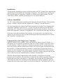
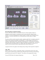
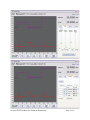
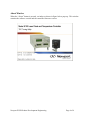
Model 6100
Laser Diode and Temperature Controller
TEC Tuning Utility
Version 1.0.2.0
Revision Date: April 5, 2010
Newport PCSB Product Development Engineering
Page 1 of 6
Introduction
This document is intended to provide a brief description of the TEC Tuning Utility shipped along
with Model 6100 Laser Diode and Temperature Controllers. This software can be used to tune
PID controller gains in Temperature Controller for different Laser Diode Mounts. The PID
control theory and the controller gain tuning process are not described here.
Software Installation
The TEC Tuning Utility may be installed on the following Microsoft Windows 32-bit operating
systems: Windows 2000 SP4 and later, Windows XP, Windows Vista and Windows 7.
The setup program for the software should start automatically when the CD accompanying the
Temperature Controller is placed in a PC. If it does not, then run Setup.exe from the Win32
folder on the CD. Follow the on-screen instructions and instructions provided in “6100 Laser
Diode and Temperature Controller CD Readme.pdf” file to install the software and USB drivers.
Following a successful installation of the software, you will be able to see a shortcut to the
software on your desktop as well as in the StartÆProgramsÆNewportÆNewport Laser Diode
and Temperature Controller menu.
Communication with Temperature Controller
When the software is run, a window a shown in figure below appears on the PC display. It
immediately tries to initialize communication with one or more controllers connected to the PC
via USB interface. If there is only one (1) controller connected to the PC, and the software is
able to successfully initialize communication with it, the software begins communication with
the controller. If it finds more than one controller, a window pops up requesting the user to
connect to a desired controller; the software begins communication with the desired controller
following the user selection. If it does not find any controller, a window pops up requesting the
user to connect at least one controller and to re-initialize communication.
When the software begins communicating with a controller, it first queries the existing
parameters in the controller. The parameters of interest for this software are mode of operation,
setpoint and actual values (Resistance or Temperature), limit settings and PID control gains.
After the present state of the controller has been obtained, the software continues to query the
setpoint and actual values at the sample rate specified on Setup tab. The default value is 0.1 sec.
Newport PCSB Product Development Engineering
Page 2 of 6
Start/Stop Data Acquisition (DAQ)
Press the “Start DAQ” button to command the software to collect setpoint resistance or
temperature, actual resistance or temperature, actual current and actual voltage from the
controller. The desired sampling interval and the number of samples can be changed from the
Setup tab. The software data buffer size is determined based on the number of samples
specified.
The software allows two data acquisition modes: continuous and fixed. In continuous mode, the
software only keeps the latest samples in its data buffer. All older samples are discarded. It
continues to acquire data until the “Stop DAQ” button is pressed. In fixed mode, the software
acquires the desired number of samples and stops the DAQ process automatically. If the number
of samples and/or the sampling interval are changed while data acquisition is underway, the
software will clear all the previously acquired data and restart the DAQ process.
A progress bar below the graph is used to display the percentage of data acquisition completed.
Tune TEC
Press the “Tune TEC” button to command the software to momentarily turn the TEC output
OFF, setup the controller (mode, setpoint, limits, PID gains) based on values specified in Setup
and PID tabs, and to turn the TEC output ON. The software will automatically start data
Newport PCSB Product Development Engineering
Page 3 of 6
acquisition process, if it has been stopped previously. The plots shown on the graph can be
turned ON/OFF by checking/unchecking desired items on Display tab.
TEC Output On/Off
Press the “TEC Output On/Off” button to toggle the TEC output enable state.
Zoom Out
This button becomes visible only when the software has previously collected some data from the
controller. Users can zoom into a portion of the graph by selecting a region around the desired
portion. Press the “Zoom Out” button to show the entire data collected.
Save Graph
This button becomes visible only when the software has previously collected some data from the
controller. Press this button to save the graph as an image file. The saved file (in JPG file
format) contains the limit settings, DAQ settings, PID settings, in addition to the graph.
Print Graph
This button becomes visible only when the software has previously collected some data from the
controller. Press this button to print the graph to your default printer. The printed file (in JPG
file format) contains the limit settings, DAQ settings, PID settings, in addition to the graph.
Save File
This button becomes visible only when the software has previously collected some data from the
controller. Press this button to save the data collected to a text file. The saved file (in JPG file
format) contains the limit settings, DAQ settings, PID settings, in addition to the acquired data.
All information in this file is tab delimited.
Setup Tabs
The software front panel has a tab control with four (4) tabs: Setup, PID, Display and Terminal.
Users can specify their desired mode of operation, setpoint, limits, and data acquisition
parameters on the Setup tab. The PID control loop gains can be changed on the PID tab. This
tab has a “Save Settings to Controller” button. Pressing this button will command the software
to save all settings in the controller’s bin #1. The display tab can be used to select desired plots
on the main graph. The plots can be scaled using the settings available on this tab. The terminal
tab can be used to send all commands supported by the controller. Please refer the controller’s
user’s manual for a complete description of commands supported by it.
Newport PCSB Product Development Engineering
Page 4 of 6
Newport PCSB Product Development Engineering
Page 5 of 6
About Window
When the “About” button is pressed, a window as shown in figure below pops up. This window
contains the software version and the controller firmware version.
Newport PCSB Product Development Engineering
Page 6 of 6