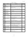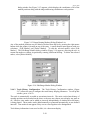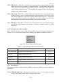
1
SOFTWARE USER’s MANUAL For The Full Utility Navigation Demonstration (FUND) Version 2.5 (Windows NT) Prepared for: National Imagery & Mapping Agency Bethesda, MD Prepared by: SPAWARSYSCEN Norfolk Code 342 2425 Stalwart Rd Building 1558 Annex Naval Amphibious Base Little Creek Norfolk, VA 23521-3325 and June 20, 2000 PRC Inc. 468 Viking Drive Virginia Beach, VA 23452-7308 June 20, 2000 Table of Contents 1 GENERAL INFORMATION ..................................................................................................................... 1-1 1.1 IDENTIFICATION ..........................................................................................................................................1-1 1.2 SYSTEM OVERVIEW ....................................................................................................................................1-1 1.3 DOCUMENT OVERVIEW ...............................................................................................................................1-1 1.4 SYSTEM REQUIREMENTS .............................................................................................................................1-1 1.4.1 PC Hardware Requirements..............................................................................................................1-1 1.4.2 Operating System Requirements.......................................................................................................1-2 1.5 ENHANCEMENTS ...........................................................................................................................................1-2 1.6 REFERENCED DOCUMENTS ............................................................................................................................1-2 2 OPERATION ............................................................................................................................................... 2-1 2.1 FUND GENERAL OVERVIEW ......................................................................................................................2-1 2.1.1 Mouse Operations.............................................................................................................................2-1 2.1.2 Keyboard Operations ........................................................................................................................2-2 2.1.3 Menus ...............................................................................................................................................2-5 2.1.4 Windows...........................................................................................................................................2-7 2.1.5 Functional Window Features............................................................................................................2-8 2.1.6 Manipulative Window Features........................................................................................................2-9 2.1.7 Help Box...........................................................................................................................................2-9 2.1.8 Active and Inactive Windows.........................................................................................................2-10 2.1.9 Advisory Windows .........................................................................................................................2-10 2.2 FUND INTRODUCTION & START-UP ........................................................................................................2-11 2.3 FUND SCREEN .........................................................................................................................................2-12 2.3.1 Permanent Displays ........................................................................................................................2-12 2.3.2 Heads-Up Displays .........................................................................................................................2-13 2.3.3 Scroll Bars ......................................................................................................................................2-14 2.4 FUND MENU BAR ....................................................................................................................................2-15 2.4.1 File ..................................................................................................................................................2-15 2.4.2 View................................................................................................................................................2-19 2.4.3 Interface ..........................................................................................................................................2-19 2.4.4 Navigation ......................................................................................................................................2-22 2.4.5 Chart ...............................................................................................................................................2-29 2.4.6 Ship.................................................................................................................................................2-35 2.4.7 DNC................................................................................................................................................2-36 2.4.8 Help ................................................................................................................................................2-37 2.4.9 Nav Toolbar....................................................................................................................................2-37 2.4.10 General Purpose Shortcut Menu.....................................................................................................2-40 2.4.11 Miscellaneous. ................................................................................................................................2-40 2.5 PRINTING IMAGES .....................................................................................................................................2-42 2.5.1 Print a Screen..................................................................................................................................2-42 2.5.2 Print a Specific Window.................................................................................................................2-43 2.6 TERMINATION ...........................................................................................................................................2-43 3 TROUBLESHOOTING .............................................................................................................................. 3-1 3.1 UNSUCCESSFUL START-UP..........................................................................................................................3-1 3.1.1 Problems Bringing Up A FUND Workstation..................................................................................3-1 3.1.2 Verifying FUND Files ......................................................................................................................3-2 3.1.3 Unable to Load the CD-ROM...........................................................................................................3-2 4 SOFTWARE INSTALLATION ................................................................................................................. 4-1 4.1 INSTALLING FUND .....................................................................................................................................4-1 i June 20, 2000 Table of Contents 5 FREQUENTLY ASKED QUESTIONS..................................................................................................... 5-1 5.1 5.2 5.3 5.4 WHAT IS FUND? ........................................................................................................................................5-1 CAN FUND READ A NIMA DIGITAL NAUTICAL CHART (DNCTM) FROM MY HARD DISK DRIVE? ...............5-1 WILL I STILL BE ABLE TO READ DNCS FROM MY CD-ROM DRIVE? ...........................................................5-1 WHAT HAPPENS IF I TAKE THE DNC CD-ROM OUT OF THE DRIVE WHILE FUND IS STILL READING THE DATABASE? ..........................................................................................................................................................5-2 5.5 HOW DO I INTERPRET THE DNC DATABASE SERVER (DDS) STATUS MESSAGES? ......................................5-2 5.6 WHY DO I SEE A BLANK SCREEN?................................................................................................................5-3 5.6.1 In Route Monitoring Mode...............................................................................................................5-3 5.6.2 Not In Route Monitoring Mode........................................................................................................5-3 5.7 WHY CAN’T I ZOOM IN OR ZOOM OUT?......................................................................................................5-3 5.8 HOW DO I BEGIN ADDING WAYPOINTS FOR ROUTE PLANNING?...................................................................5-3 5.9 HOW DO I CREATE AND LOAD MY OWN DEMO ROUTES? .............................................................................5-3 5.10 WHAT ARE THE FUTURE PLANS FOR FUND SOFTWARE? ........................................................................5-3 5.11 WHO ARE THE FUND SOFTWARE POINTS OF CONTACT? .......................................................................5-4 5.12 WHO DO I CONTACT FOR FUND TECHNICAL SUPPORT? ........................................................................5-4 5.13 WHO DO I CONTACT TO GET ADDITIONAL DIGITAL NAUTICAL CHARTS (DNCS)?..................................5-4 5.14 NOTES ABOUT GPS RECEIVERS: ............................................................................................................5-4 5.14.1 FUND DOES NOT WORK WITH THE AN/WRN-6 OR AN/SRN-25 EQUIPMENT. ................5-4 5.14.2 FUND DOES WORK WITH THE PLGR (AN/PSN-11)!...............................................................5-4 5.14.3 FIVE DIAGNOSTIC QUESTIONS FOR DETERMINING AN/PSN-11 PLGR MODEL: ...........5-5 5.14.4 FUND WORKS WITH MANY COMMERCIAL GPS RECEIVERS. ...........................................5-6 5.14.5 FUND REQUIRES CERTAIN NMEA 0183 DATA SENTENCES FROM A GPS RECEIVER. .5-6 6 ACRONYMS AND ABBREVIATIONS .................................................................................................... 6-1 7 HOT KEYS QUICK REFERENCE........................................................................................................... 7-1 ii June 20, 2000 List of Figures Figure 2-1. Representative Menus .............................................................................................. 2-5 Figure 2-2. Functional and Manipulative Window Features ...................................................... 2-7 Figure 2-3. Warning Window ................................................................................................... 2-10 Figure 2-4. FUND Screen at Startup ........................................................................................ 2-11 Figure 2-5. FUND Menu Bar.................................................................................................... 2-15 Figure 2-6. Demo Control Window .......................................................................................... 2-15 Figure 2-7. Load Demo Route Dialog Window........................................................................ 2-16 Figure 2-8. Library Control Window........................................................................................ 2-18 Figure 2-9. Exit FUND Warning Window ............................................................................... 2-18 Figure 2-10. Dead Reckoning Fix Window............................................................................... 2-20 Figure 2-11. Configure GPS Interface Window ........................................................................ 2-21 Figure 2-12. Navigation Status Window ................................................................................... 2-21 Figure 2-13. Magnetic Variation Window................................................................................. 2-23 Figure 2-14. Create Bearing Range Mark Dialog Window ....................................................... 2-23 Figure 2-15. Range Bearing Markers Dialog Window List....................................................... 2-24 Figure 2-16. Edit Range Marker Dialog Window ..................................................................... 2-24 Figure 2-17. Track History Configuration................................................................................. 2-25 Figure 2-18. Read Primary Route File Dialog Window ............................................................ 2-26 Figure 2-19. View Route Dialog................................................................................................ 2-27 Figure 2-20. Edit Waypoint Dialog ........................................................................................... 2-27 Figure 2-21. Charts In Library Window .................................................................................... 2-29 Figure 2-22. Chart Notes Window............................................................................................. 2-30 Figure 2-23. Chart Quality Window .......................................................................................... 2-30 Figure 2-24. Mariner Toolbar .................................................................................................... 2-31 Figure 2-25. View Mariner List................................................................................................. 2-33 Figure 2-26. Standard Layer Dialog Window ........................................................................... 2-34 Figure 2-27. Range & Bearing Configuration Window ............................................................ 2-35 Figure 2-28. Load DNC Database Window............................................................................... 2-37 Figure 2-29. Nav Toolbar .......................................................................................................... 2-38 Figure 2-30. General Purpose Shortcut Menu ........................................................................... 2-40 Figure 2-31. Spatial Query Window.......................................................................................... 2-41 Figure 2-32. Extended Query Information Window.................................................................. 2-42 Figure 3-1. Representative dir File Listing................................................................................. 3-2 List of Tables Table 2-1. Table 2-2. Table 2-3. Table 2-4. Table 2-5. Table 2-6. Table 5–1. Mouse Manipulation Terms ...................................................................................... 2-2 Hot Keys.................................................................................................................... 2-3 Keyboard Substitutes for Menu Commands.............................................................. 2-5 Mariner Toolbar Buttons ......................................................................................... 2-32 Nav Toolbar Buttons ............................................................................................... 2-38 General Purpose Shortcut Menu Functions............................................................. 2-40 National Stock Numbers and Part Numbers for AN/PSN-11 PLGR........................ 5-6 iii June 20, 2000 1 GENERAL INFORMATION 1.1 Identification This Software User’s Manual (SUM) applies to the Windows NT version of the Full Utility Navigation Demonstration (FUND) software. FUND software was developed for the National Imagery & Mapping Agency (NIMA) by SPAWARSYSCEN Detachment Norfolk, Code 342 and PRC Inc., Virginia Beach, VA. 1.2 System Overview FUND is used to demonstrate the functionality of NIMA's Digital Nautical Chart (DNC) database. Display of DNC on FUND provides the tools and features of an Electronic Chart Display and Information System (ECDIS) and allows the user to exploit the functionality inherent in DNC to meet International Maritime Organization(IMO) and/or International Hydrographic Organization(IHO) standards. FUND utilizes the DNC database directly with no pre-processing or re-formatting and allows sensor inputs for devices such as Global Positioning Systems (GPS). FUND has been developed and will continue to be supported in the Windows NT operating system environment. Future versions of the FUND software will support DNC updating methods and full NIMA GEOSYM 4 symbology implementation. 1.3 Document Overview The purpose of this document is to provide instructions for operating the FUND software, Version 2.5. 1.4 System Requirements Hardware and software requirements required for use of the FUND software. 1.4.1 PC Hardware Requirements • • Bare Minimum Configuration Intel Pentium/Pentium Pro—200MHz 15” diagonal monitor; 1024x768 resolution; 256 colors • • • • • * 96 MB memory 2 GB hard disk drive with: → 550 MB free and * → Recommended /Initial paging file size; The Maximum Size should be at least double the above number. 6X or greater CD-ROM COM port (Serial, ANSI RS-232) Mouse or trackball • • • • • • • Recommended Configuration Intel Celeron/Pentium II/III—300MHz 19” diagonal or larger monitor; 1280x1024 res. and 65536 (16-bit) colors at 75Hz vertical refresh rate 128 MB memory or greater 6 GB hard disk drive with: → 1 GB free space and → 250-300 MB Initial Size paging file 40X CD-ROM COM port (Serial, ANSI RS-232) Mouse or trackball RECOMMENDED PAGING FILE SIZE: Press the right mouse/trackball button with the cursor positioned over the My Computer icon. Select the Properties menu option. Then, select the Performance tab from the System Properties dialog. Under the Virtual Memory 1-1 June 20, 2000 heading, press the Change button. Locate the heading Total Paging File Size for All Drives. You will find the Recommended number of Megabytes calculated by Windows NT. 1.4.2 Operating System Requirements • Microsoft Windows NT 4.0 Workstation with Service Pack 4 applied. • System Properties: The optimal screen resolution is 1280x1024 pixels; if FUND dialog text or the transparent overlay text (in the chart window heads-up/status displays) appear too small to be easily read, try a lower screen resolution. The minimum considered should be 1024x768. Set colors to at least 65,536 (16-bit) if available. For comfortable, and long-term CRT viewing, set the Display Properties monitor vertical refresh rate to at least 75Hz. Set Application Performance Boost to maximum. 1.5 Enhancements FUND version 2.5 has many improvements over version 2.3beta. Major areas of improvement include operating performance, display presentation, GPS receiver support, and memory management. In addition, FUND now remembers the state of the application via Windows registry entries. Such things as GPS settings, toolbar configuration, and operating mode are now saved upon shutdown. 1.6 Referenced Documents International Hydrographic Organization (IHO) S-52 “Specifications for Chart Content and Display Aspects of ECDIS” Appendix 1: Guidance on Updating the Electronic Navigational Chart Appendix 2: Provisional Color and Symbol Specifications for ECDIS Appendix 3: Glossary of ECDIS-related Terms National Imagery and Mapping Agency (NIMA) MIL-STD-2407 Vector Product Format Specification dated 28 June 96 National Imagery and Mapping Agency (NIMA) MIL-PRF-89023 Digital Nautical Chart Specification International Maritime Organization (IMO) Resolution A.817(19): “Performance Standards for Electronic Chart Displays and Information Systems (ECDIS)” dated 23 November 1995. PLGR+96 Operations and Maintenance Manual Precision Lightweight GPS Receiver PLGR+96 Northstar GPS Chart Navigator Operator’s Manual 951X/951XD Software Version 2.06 1-2 June 20, 2000 2 OPERATION This chapter includes procedures for Initialization, User Inputs, System Inputs, Termination, Restart, and Outputs of the FUND Software. 2.1 FUND General Overview This section describes how to begin operating the FUND system by using standard control features including the keyboard and mouse. The system employs the mouse as the primary operator interface, relying on keyboard strokes only to facilitate actual data entry. The main tools for controlling program flow are the toolbars, drop-down menus, pop-up menus and windows, and various mouse clicking operations used to select items from lists of optional activities. Using the FUND involves interaction with a number of on-screen items and displays. This section identifies and discusses the commonly-used interfaces. 2.1.1 Mouse Operations 2.1.1.1 PC. The mouse is connected by a cable to the keyboard or computer (depending upon hardware configuration). Moving the mouse causes the pointer to move correspondingly on the monitor. 2.1.1.2 Laptop. Laptop configurations vary. One of the more common laptop configurations has a built-in mini-joystick with two buttons below the keyboard that correspond to the mouse buttons. 2.1.1.3 General. The mouse pointer has several different display modes. When the mouse pointer is in a menu operation (drop-down menu or pop-up menu), it appears as an arrow. When the pointer is used to select (highlight) an alphanumeric field, a cursor is displayed in that field. When the pointer resembles cross-hairs (+), it is in the map area of the display and is accessible to the user. When the pointer resembles a clock, it indicates that the system is busy. When certain features are active, the cursor takes on special characteristics associated with the selected feature. These are described in the appropriate sections of the manual. The terms in Table 2-1 are used in reference to mouse manipulation: NOTE The left and right mouse buttons are used to perform different functions, but pressing any of them is known as “clicking.” 2-1 June 20, 2000 Table 2-1. Mouse Manipulation Terms TERM DEFINITION Point: To move the pointer via the mouse so that it is over an object or menu item. Click: To press the left or right mouse button once and release. In this manual, “click” alone refers to the left button, which is the most commonly used. Clicking with the right button is referred to as a “right-click”. Doubleclick: To press the mouse button twice in rapid succession without moving the cursor. Drag: To press a mouse button and hold it down while moving the pointer on the screen. The drag operation is completed by releasing the button. Select: To point at and click an item or button within a pop-up menu or pop-up dialog window. When the button is released, the item is selected. In some instances the item will be highlighted or a flashing cursor will appear. Deselect: To point at and click an item or button already selected, i.e., with the indicator “On,” will turn the item “Off”. 2.1.2 Keyboard Operations 2.1.2.1 Key and Keystroke Identification. a. Keyboard keys are identified in instructions or descriptions in this manual by enclosing the letter or description of the key in pointed brackets, e.g., <Tab>. b. Alphabetic keys are identified by the capital letter enclosed in pointed brackets, e.g., <A>. c. If two or more keys are to be pressed in succession, releasing each before pressing the next, they are bracketed separately, e.g. <Tab> <Enter>. d. If one key is to be held down while another is pressed, they are separated by hyphens and bracketed together, e.g., <Alt-F>. 2.1.2.2 Keyboard Applications. The principal use of the keyboard is to enter specific data in edit fields, but there are some keyboard shortcuts that can be substituted for certain mouse operation. a. <Tab> can be used to move between fields in a dialog window. b. The space bar can be used in place of the left mouse button to make selections in dialog windows. c. All menu bar entries can be accessed by holding down <Alt> and pressing the underlined letter of the desired menu item, e.g., to access the File menu, press <Alt-F>. 2-2 June 20, 2000 d. The left, right, up, and down arrow keys can be used to maneuver in drop-down menus. e. <Enter> can be used to select a highlighted menu option. f. The function keys and some of the alphabetic keys have operational assignments. These are called “hot keys.” Table 2-2 is a list of hot keys. Hot keys only work when the chart window is active. If a hot key does not work, click on the chart window. g. In addition to the hot keys, several keyboard entries can be substituted for menu-initiated operations. These substitutes are listed in Table 2-3. Table 2-2. Hot Keys Key Function Explanation Paragraph F1 Help Press to display hot key list 2.4.8.1 F2 Base Display Mode Press to display chart in Base Display Mode. 2.4.5.4.5 a F3 Standard Display Mode Press to display chart in Standard Display Mode. 2.4.5.4.5 b F4 Other Display Mode Press to display chart in Other Display Mode. 2.4.5.4.5 c F5 Toggle Route Monitoring Press to Toggle Route Monitoring On and Off 2.4.5.4.3 F7 Enable all Heads-Up Displays Press to enable all Heads-Up Displays. 2.3.2 F8 Disable all Heads-Up Displays Press to disable all Heads-Up Displays. 2.3.2 + Zoom in Press to double the magnification of the chart display. 2.4.9.1 (Not available in Route Monitoring Mode) - Zoom out Press to halve the magnification of the chart display. 2.4.9.2 (Not available in Route Monitoring Mode) A Add Range/Bearing Marker Press to place a range/bearing marker on the chart. 2.4.4.2.1 B Toggle Fixed Bearing Line Press to toggle a fixed bearing line on or off. 2.4.6.1 C Clear Chart Offset Returns ownship to the center of the screen (Relative Motion Mode only). 2.4.11.3 2-3 June 20, 2000 Table 2-2. Hot Keys Key Function Explanation D Toggle DNC Database Press to toggle the DNC Database Message on or Message off. F Tag Waypoint Place pointer over a waypoint and press to tag the waypoint for deletion. Paragraph 2.3.2.3 2.4.4.4 d (Press <Delete> to delete tagged waypoints) G Toggle Great Circle/Rhumb Line Press to toggle planned route between great circle and rhumb line. 2.4.4.4 e H Toggle Primary/ Secondary Route Press to toggle between primary and secondary routes. 2.4.4.4.5 I Toggle Ownship Information Display Press to toggle Ownship Information windows on or off. 2.3.2.1 M Mark Ownship Position Press to place a time mark on ownship track. 2.4.4.3 (Manual Track Mode only) O Enter Chart Offset Press to enable ownship to be moved from the center of the screen. 2.4.11.3 (Relative Motion Mode only) P Toggle Pointer Position Display Press to toggle the Pointer Position windows on or off. Q Move or Insert Waypoint Position pointer on a waypoint and press to enable it to be dragged, or create a new waypoint by pressing while the cursor is on the line between two existing waypoints. R Toggle Range Ring Press to toggle the range ring on or off. 2.4.6.1 S Toggle Scale Bar Text Label Press to toggle the Scale Bar Text Label on or off. 2.3.1.5 T Toggle CD Text Press to toggle the CD-ROM index text on or off. 2.4.11.1 (Browse Chart Only) 2-4 2.3.2.2 2.4.4.4 b, c June 20, 2000 Table 2-2. Hot Keys Key Function Explanation Paragraph 2.4.4.4 a W Add Waypoint To add a waypoint at the end of the existing Primary route, place pointer at position of desired waypoint and press. X Dead Reckoning Position Fix at Pointer Lat/long Press to place a DR fix at pointer position. 2.4.3.1 Table 2-3. Keyboard Substitutes for Menu Commands Key Function Explanation Paragraph Ctrl-Q Quit Press to quit FUND 2.4.11 Ctrl-L Library Press to enable Library Control function 2.4.1.2 Ctrl-M Update Mouse Coordinates Press to toggle mouse coordinate update on or off Ctrl-R Refresh Press to redraw updated chart. 2.1.3 2.4.5.4.1 2.4.2.4 Menus A menu is a list of user choices (Figure 2-1). Menus used in FUND include top-level menus, drop-down menus, submenus, and shortcut menus. Drop-Down Menu Top-Level Menu Submenu Shortcut Menu Figure 2-1. Representative Menus 2-5 June 20, 2000 2.1.3.1 Top-Level Menus. A top-level menu consists of a menu name and menu items. The menu items identify the category of commands or options in the associated drop-down menus. Clicking a menu item causes a drop-down menu to appear, listing a group of related options. This function can also be performed from the keyboard by holding down the <Alt> key and typing the underlined alphanumeric associated with the desired menu option. After a menu is selected, the user may change to a different menu selection by pressing an underlined alphanumeric, using the mouse, or using the left or right arrow keys on the keyboard. 2.1.3.2 Drop-down Menus. When a drop-down menu is displayed, the user can select one of the options that is available by moving the mouse pointer down the menu. As the user drags the pointer over the options, they are highlighted. To select an option, click it while it is highlighted. Most menus are sticky. For example, drop-down menus can be accessed in such a way that they remain on the screen even though the left mouse button is no longer depressed. To see the sticky menu effect, click to pull down a menu and release the button without making a selection. Clicking again while the pointer is on a menu item selects that option. To unstick or close the menu, simply press <ESC> or click on an area outside the menu. 2.1.3.3 Submenus. A submenu is a menu that is displayed as an option from another menu. When the user moves the pointer to the far right of a highlighted menu option with an arrowhead (8) displayed to the right of the option label, a submenu appears to the right of and below the highlighted option. 2.1.3.4 Shortcut Menus. A shortcut menu appears at the location of the cursor when the right mouse button is clicked. Shortcut menus provide content-sensitive commands and options. 2.1.3.5 Inactive Menu Options. Certain menu options appear in grayed out text when a menu is accessed and do not highlight as the mouse pointer passes over them. These menu options are inactive; they cannot be selected by the user in the current operating state. References to menu selections, including cascading menus, are shown in this manner: MENU BAR ITEM 8 MENU ITEM 8 SUBMENU ITEM or MENU BAR ITEM 8 indicates hierarchical menu selection MENU ITEM 8 starting at the MENU BAR which is on SUBMENU ITEM the top border of the chart window 2-6 June 20, 2000 2.1.4 Windows A window (Figure 2-2) is a screen within the main screen, which is used to hold information that relates to a particular option. A window may have some or all the window features described in the following sections. Dialog Title Drag Box Close Box Subgroup Radio Buttons Edit Field Combo Box Check Boxes Scroll Arrow Scroll Bar Scrolled List Buttons Figure 2-2. Functional and Manipulative Window Features 2.1.4.1 Window Boxes. Related features are often combined in logical subgroups within a window. These groupings of features are usually contained within boxes and are called window boxes or subwindows. Each window has a title describing its contents. 2.1.4.2 Scroll Windows. A scroll window is displayed whenever there is a list of data in the window that requires more space than is available. Scroll windows contain a scroll bar directly to the right of the window and includes two arrows, one pointing up and the other pointing down. Scroll Windows are used when all of the available data cannot fit into one viewing window. To view more data, click on the scroll bar arrows. (Click the down arrow to scroll down the list, the up arrow to scroll up.) Holding the left mouse button on the up or down arrow causes the data to scroll automatically. 2-7 June 20, 2000 The scroll bar also contains a scroll box which indicates the position of the list section currently displayed relative to the entire list. Dragging and releasing the scroll box causes the section of the list related to the new scroll box position to be displayed in the scroll window. Clicking the left mouse button in the scroll box moves the scroll box and its related list section upward. Clicking the right mouse button in the scroll box moves the scroll box and its related list section downward. The scroll bar position can also be adjusted by using the Up and Down arrow keys on the keyboard; however, the Scroll Window must be selected. 2.1.4.3 Dialog windows. Dialog windows are any windows that request user input. The user may comply and acknowledge the interaction or abort by clicking the Cancel or Done buttons. 2.1.5 Functional Window Features There are certain features found in many windows that are used for setting parameters, entering data, and accepting or rejecting user entries. These features include buttons, check boxes, combo boxes, radio buttons, edit fields, and window pop-up menus. Collectively, they are called functional window features. 2.1.5.1 Buttons. Buttons are rectangular raised symbols. Each button contains a label indicating the function which it serves. Point to a button and click to perform the action on the button’s label. The button will appear pressed. Onscreen buttons are identified in this manual by enclosing their label in square brackets, e.g., [OK]. The following buttons are among those most commonly used in the system: [OK] Causes a window to disappear, but saves any changes that have been made. [APPLY] Saves any changes that have been made, but does not cause the window to disappear. [DONE] Causes the window to disappear. [CANCEL] Causes a window to disappear from the screen without saving any changes that have been made. 2.1.5.2 Radio Buttons. Radio buttons are used to select one choice from a group of features. Radio buttons appear as small spheres on the screen. To choose a feature associated with an individual radio button, point at the button, or onto the line containing the button, and click. A black dot appears within the sphere of the radio button to show that the button is selected. The black dot in any previously selected button simultaneously disappears so that only one button is selected. 2.1.5.3 Check Boxes. Check boxes are similar to radio buttons, but they allow the simultaneous selection of many features. Check boxes appear as small squares on the screen. To choose a feature associated with the checkbox, point at the checkbox, or onto the line containing the checkbox, and click. The checkbox displays a check mark to show that the checkbox is selected. To deselect a checkbox, click it again. The user may select any combination of check boxes. 2-8 June 20, 2000 2.1.5.4 Edit Fields. An edit field is a box in a window in which the user may enter keyboard data. To enter data into an edit field, point at the edit field and click to highlight the field. When an edit field is highlighted, a cursor appears below one of the characters in the field. As keyboard text is entered in the highlighted field, it appears at the point of the cursor. The user may use the Up/Down and Left/Right arrow keys to change character position of the cursor before entering keyboard text. If there are several edit fields in a sequence, the user may press the TAB key to move the highlight to the next edit field in the sequence. When all editing is complete, click the appropriate button (e.g., [OK], [APPLY]) to apply the newly entered data. 2.1.5.5 Combo Boxes. A combo box is an edit field with a list of selectable entries. The list of entries can be viewed by clicking the 6 button on the combo box and pulling the cursor up and down the list. An item in the list can be selected by clicking the pointer on the desired item. 2.1.6 Manipulative Window Features Manipulative window features include drag bars, minimize boxes, upsize/downsize boxes, and close boxes. 2.1.6.1 Drag Bar. A drag bar is a colored bar at the top of a window. A window can be moved around the screen with the drag bar. To move a window, point to the drag bar and hold down the left mouse button. Drag the window to the desired area of the screen and release the button. 2.1.6.2 Minimize Box. The FUND main screen has a minimize box. An minimize box is a small box near the upper right corner of the window containing an underline. Clicking on this box causes the selected window to disappear and be replaced by an icon. 2.1.6.3 Upsize/Downsize Box. The FUND main screen has an upsize/downsize boxes in upper right corner. When the window is not filling the entire available screen space, it contains a single square; clicking on it expands the window to fill the entire available screen space. When the window is filling the entire available space, it contains two overlapping rectangles with thick upper borders; clicking on it shrinks the window either to a previously selected size or a size small enough to allow for manual sizing. 2.1.6.4 Close Box. A close box is a small box in the upper right corner of a window containing an X. Clicking this box closes the window. Not all windows have close boxes. 2.1.7 Help Box Some windows have a help box. A help box is a small box near the upper right corner of a window containing a question mark. Clicking this box adds a question mark to the cursor; when the cursor is clicked on a part of window, a note explaining its use or function appears. 2-9 June 20, 2000 2.1.8 Active and Inactive Windows While several windows can be open on the screen at once, only one window can be active. The active window is the window currently being worked on and can be identified by the drag bar which is a different color (blue) from the drag bars of the other windows on the screen (gray). All other windows on the screen are inactive. An inactive window may be partially or fully obscured by other windows. To activate an existing window, point at any visible part of the window and click on it. This causes the drag bar of the activated window to change color and the window to “move in front of” any windows that overlap it. 2.1.9 Advisory Windows Advisory windows appear to call the user’s attention to certain situations and make it less likely to make a wrong choice accidentally. A confirmation window appears when the user selects an option such as Exit, which is not routinely used. A WARNING window appears when some operation which is harmful to previously entered data is about to occur. WARNING windows (Figure 2-3) inform the user that data will be altered, and give the user a chance to continue or abort the operation. The user must acknowledge the WARNING window before he can interact with any other portion of the FUND. Figure 2-3. Warning Window Occasionally, when invalid data is entered or an operation cannot be performed, a WARNING window is displayed to inform the user that the requested action cannot take place. When a WARNING window appears, the user must click the appropriate button in the WARNING window to continue with the current operation. 2-10 June 20, 2000 2.2 FUND Introduction & Start-Up To start FUND, click the Windows NT Start button and select “FUND” or select FUND from a shortcut Icon on the desktop. FUND can also be started by selecting “fundDib.exe” from Windows NT Explorer under the c:\fund25\bin directory. After a brief interval, the FUND Screen (Figure 2-4) appears. Figure 2-4. FUND Screen at Startup If a DNC volume is in the CD-ROM at start-up, then FUND will begin to initialize the DNC volume from the CD-ROM automatically. If the CD-ROM drive is empty, the operator must manually load a DNC volume from the DNC menu. The DNC volume can be on any drive visible to the system (see section 2.4.7.1). Once FUND has started, the operator can choose the desired position source (DEMO, Dead Reckoning, GPS). Demo is the default position source and is best for new users to experience the capabilities of the FUND Software. Select a demo route and hit play to begin simulating ownship’s motion (see section 2.4.1.1). 2-11 June 20, 2000 The following elements appear at startup, referenced to the section of this manual in which they are discussed in detail. FUND Screen 2.3 FUND Menu Bar 2.4 FUND Tool Bar 2.4.2.1 FUND Status Bar 2.3.1.6 Scroll Bars 2.3.3 FUND Mariner Tool 2.4.2.2 The default mode of operation for FUND Software is with Route Monitoring enabled and with Non-Relative Motion selected (see sections 2.4.5.4.3 and 2.4.5.4.7). In this mode of operation charts will be automatically re-drawn by FUND when ownship moves outside of an adjustable bounding rectangle; preventing ownship from sailing off the screen. When Relative Motion is selected with Route Monitoring enabled, ownship will remain at a fixed location on the screen and the chart will automatically scroll underneath the ship at a 1Hz rate. To browse individual Digital Nautical Charts (DNCs), Route Monitoring mode must be disabled. Once Route Monitoring has been disabled, selecting Library Control (see section 2.4.1.2) will allow the user to choose individual charts from the currently loaded CD (see section 2.4.7.1). Depending on the size of the chart, loading a library for the first time may take anywhere from 510 seconds up to 10 minutes or more. Once a library has been selected and begins loading choosing the Fit Library to Screen operation (see section 2.4.5.2) will fit the Library to the viewing area. Chart Zooming may be accomplished by either using the [+] and [-] keys or by using the mouse and toolbar buttons (see sections 2.4.9.1 and 2.4.9.2). When Relative Motion is selected with Route Monitoring Disable the scroll bars can be used to pan the chart (see 2.3.3). The arrow keys can also be used to pan the chart when Non-Relative Motion is selected and Route Monitoring is Disabled. NOTE Manually panning and zooming in and on the chart can only be accomplished when Route Monitoring is DISABLED. 2.3 FUND Screen The FUND Screen (Figure 2-4) displays a world map with ownship at 0° Latitude, 0° Longitude. The following features appear on the screen. 2.3.1 Permanent Displays The following displays always appear on the FUND screen. 2.3.1.1 Ownship Symbol. Ownship in represented on the screen by two concentric circles. 2.3.1.2 Velocity Vector. The Velocity Vector is a line that extends from the ownship symbol provides a visual indication of ownship heading and speed and shows where ownship 2-12 June 20, 2000 position will be in from one to six minutes if the current course and speed are maintained. If ownship speed is zero, the velocity vector does not appear. 2.3.1.3 DNC Data Display. This display in the upper left corner of the screen provides the following basic information: Scale (S): The scale at which the DNC is drawn on the screen. The default scale for the Browse chart is 1:31,000,000. If “U” appears after the scale readout, the chart is “under scale,” which means that the video presentation cannot show all available details. If “O” appears after the scale readout, the chart is “over scale,” which means that the video presentation is too large to be accurate. Range (R): The unit of measure in which distance is displayed. The default is nautical miles (NM). Depth (D): The unit of measure in which depth is displayed. The default is meters. Height (H): The unit of measure in which height above the surface is displayed. The default is meters. Mode The mode of the chart display: Base, Standard, or Other. See Section 2.4.5.4.5 for explanation of display modes. 2.3.1.4 North Arrow. The North Arrow appears in the upper right corner of the screen to serve as a reminder that north is always up. 2.3.1.5 Scale Bar. The permanent scale bar appears on the left side of the screen near the center. The text identifying the scale can be toggled on and off by pressing <S>. 2.3.1.6 Status Bar. The Status Bar at the bottom of the screen displays the following information: Ship Library: Identifies the library in which the ownship symbol is located. If AUTO library is active this is also indicated followed by the best selected library for ownship’s position. Mouse library: Identifies the library in which the cursor is located. If a screen display straddles two charts, these two could very well be different. GPS: 2.3.2 If no GPS is connected or if a connected GPS is not functioning, this box reads GPS OFFLINE. If a GPS is connected and functioning, this box reads GPS ONLINE. Heads-Up Displays The following heads-up displays appear by default on the FUND screen. They can be toggled on and off. To enable all heads-up displays, press <F7>. To disable all heads-up displays, press <F8>. Individual displays can be toggled separately as described. 2.3.2.1 Ownship Information Display. Ownship information appears in three windows at the top center of the screen. To toggle these windows on or off, press <I>. 2-13 June 20, 2000 2.3.2.1.1 Position Window. The first window displays ownship latitude in degrees, minutes, and hundredths of a minute (i.e., dd mm.mm) north or south (N or S); and longitude in degrees, minutes, and hundredths of a minute (i.e., dd mm.mm) east or west (E or W). This position is normally determined automatically by the Selected Position Source. 2.3.2.1.2 Speed/Heading Window. The second window displays ownship heading as COG (Course Over Ground) in degrees and hundredths of a degree, and SOG (Speed Over Ground) in knots and tenths of a knot. Whenever the SOG is less than 0.5 knots, the COG indicator reads N/A. 2.3.2.1.3 Time, Date, and Scale Window. Although not actual ownship information, this window toggles on and off with the previous two. Time is GMT (UTC) displayed in 24-hour format. Date is shown in military format (day month year). Scale is shown as a ratio. If “U” appears after the scale readout, the chart is “under scale,” which means that the video presentation cannot show all available details. If “O” appears after the scale readout, the chart is “over scale,” which means that the video presentation is too large to be accurate. This information can be used to infer the accuracy of the displayed chart data. 2.3.2.2 Pointer Position Display. Pointer position information appears in two windows at the lower left corner of the screen. To toggle these windows on or off, press <P>. 2.3.2.2.1 Position Window. The first window displays pointer latitude and longitude in degrees, minutes, and hundredths of a minute. 2.3.2.2.2 Range/Bearing Window. The second window displays the pointer position relative to ownship. Range (RNG) is displayed in nautical miles and bearing (BRG) in degrees and tenths of a degree. When the distance tool (see para. 2.4.9.4) is used, an additional window is displayed to the right of the range and bearing window to display the range and bearing between two chosen points. 2.3.2.3 DNC Database Message Window. The most recent CD-ROM activities are displayed in the lower right corner of the screen. To toggle this window on or off, press <D>. 2.3.3 Scroll Bars The FUND screen has part-time scroll bars on the right side and the bottom. They are only active when the system is operating with Route Monitoring mode disabled with relative motion enabled (2.4.5.4.7). The scroll bars have arrows at the end indicating the scrolling direction. To view other chart areas, click on the scroll bar arrows. Holding the button on an arrow causes the screen to scroll continuously. The scroll bars also contain scroll boxes which indicates the position of the chart section currently displayed. Dragging and releasing the scroll box causes the section of the list related to the new scroll box position to be displayed in the scroll window. 2-14 June 20, 2000 2.4 FUND Menu Bar The FUND Menu Bar is located at the top of the FUND display (Figure 2-5). The menu bar contains the following entries: File, View, Interface, Navigation, Chart, Ship, DNC, and Help. Each entry has an associated drop-down menu. Figure 2-5. FUND Menu Bar 2.4.1 File The options on the File drop-down menu are Demo, Library and Exit. 2.4.1.1 Demo. Selecting Demo displays the Demo Control window (Figure 2-6). The window contains a menu bar, four status lines, and three buttons. Figure 2-6. Demo Control Window The user can create many different routes with the planned route utility and save them to disk. The demo follows from start to end and either stops or returns from end to start. To load the current Primary Route the user must first save the route under the Navigation 8 Planned Route 8 Save Route 2-15 June 20, 2000 2.4.1.1.1 Menu Bar. The menu bar contains the following entries: File, Edit, and Options. Each entry has an associated drop-down menu. a. Selecting the File menu displays one option: Load. When Load is selected, the Load Demo Route dialog window (Figure 2-7) appears. This window displays all the current route files. Figure 2-7. Load Demo Route Dialog Window There are two ways to select a route: (a) Double click on a filename in the upper portion of the dialog window. (b) Type the route file name in the ‘Selection’ portion of the dialog window. b. Selecting the Edit menu displays two options: (1) ARPA: When ARPA (Automatic Radar Plotting Aid) is selected, the DEMO CONTROL - ARPA Contacts window appears. This feature is not currently implemented, so no actions can be taken with this screen. (2) Route. When Route is selected, c. Selecting the Options menu displays a single option: Looping. If the looping option is selected, the current route reverses course when the end of the route is reached. If it is not selected, the demo stops when it reaches the end of the route. 2-16 June 20, 2000 2.4.1.1.2 Status Lines. The window contains MODE, ROUTE, LEGS, and PLAYTIME status lines. a. The MODE line displays the mode of the currently loaded demo route. If no route is loaded, the entry reads “STOPPED.” (1) PLAYING: The currently loaded route is running. (2) STOPPED: The currently loaded route is stopped. b. The ROUTE line displays the filename of the demo route that is currently loaded. If no route is loaded, the entry reads “EMPTY.” c. The LEGS line displays the number of legs in the selected demo route. If no route is loaded, the entry reads “0.” d. The PLAYTIME line displays the total time required to run a demo route in hours, minutes, and seconds, i.e., hh:mm:ss. If no route is loaded, the entry reads “00:00:00.” 2.4.1.1.3 Buttons. The window contains [Play], [Stop], and [Close] buttons. a. [Play] Click to play the selected route and close the DEMO CONTROL window. b. [Stop] Click to stop the route. c. [Close] Click to close the DEMO CONTROL window. 2.4.1.2 Library. Normally, the FUND software automatically uses the library with the best scale data at the current location of ownship. The user can manually override this automatic library selection using the Library Control function of the File menu. When the Library Control function is selected, the Library Control window (Figure 2-8) appears on the screen. This function can also be enabled by pressing <Ctrl-L>. The upper part of the Library Control window shows all the libraries currently available to the user. The currently selected library is indicated by a black indented radio button. The lower part of the Library Control window shows the name, projection type, extent, and scale for the library currently selected in the upper part of the window. To change to a new library, click on the line containing the desired library, and then click [OK] or [APPLY]. The chart screen will be refreshed with information from the specified library. To dismiss the Library Control window without affecting the current chart display, click [CANCEL]. 2-17 June 20, 2000 Figure 2-8. Library Control Window NOTE If the current extent of the chart screen does not intersect the extent of the specified library, no data will be displayed. If this occurs, the user should either select a more appropriate library, or change the extent of the screen by scrolling, zooming, or selecting the Fit Library To Screen function in the Chart Tools menu. 2.4.1.2.1 Exit. The EXIT command is used to stop or secure the FUND MMI operation. When the user selects this option, the system responds with a WARNING window (Figure 2-9). If the user clicks [YES], the FUND MMI exits. Clicking [NO] negates the initial EXIT command and closes the WARNING window, permitting the MMI to continue to operate. This function can also be performed by pressing <Ctrl-Q>. Figure 2-9. Exit FUND Warning Window 2-18 June 20, 2000 2.4.2 View The options on the View drop-down menu are Nav Toolbar, Mariner Toolbar, Monitor Size, and Refresh. 2.4.2.1 Nav Toolbar. Selecting this option toggles the Nav toolbar, which normally appears immediately below the menu bar, off or on. The Nav toolbar is explained in detail in section 2.4.10. 2.4.2.2 Mariner Toolbar. Selecting this option toggles the Mariner toolbar on or off. The Mariner toolbar is explained in detail in paragraph 2.4.5.3. 2.4.2.3 Monitor Size. Selecting this option enables the operator to select the monitor size of the computer being used, from 14” to 32”. At smaller sizes there will be some overlap in elements on the screen. 2.4.2.4 Refresh. Selecting this option redraws the display. In Route Monitoring Mode, the display is redrawn with ownship at center. This function can also be performed by pressing <Ctrl-R> 2.4.3 Interface The options on the Interface drop-down menu are Dead Reckoning, GPS, and Position Source. 2.4.3.1 Dead Reckoning. When the Dead Reckoning Input option is selected from the Navigation drop-down menu, the Dead Reckoning Fix window (Figure 2-10) appears. This window permits the user to enter a position fix that will update the FUND DEAD RECKONING position estimate. This option may be used when a valid external fix is obtained from radar, celestial, or other means and it is desired to update the current FUND DR position. By moving the pointer arrow to the first line of the position field the user wishes to edit (i.e., Latitude), the field is highlighted and the user can enter the new latitude obtained from external fix by typing the correct value. Similarly, moving the pointer to the Longitude field, utilizing the Tab key, highlights that field and the user can change the longitude value as required. The fix UTC is entered in the same way. NOTE Pressing <Return> in any of the edit fields has the same effect as clicking [OK]. <Tab> or the mouse pointer should be used to move to the next edit field. Clicking [CANCEL] in the DEAD RECKONING window at any time will cause all edit changes to be ignored, the DEAD RECKONING function to be terminated, and the window to close. Otherwise, when the user has entered all the necessary input data in the proper fields, click [OK] to accept the new values. When [OK] is clicked, the system may respond by displaying a WARNING window as shown in Figure 2-3. This window shows the distance of the manually entered fix from the current ownship position. The user must verify the manually entered fix by clicking [ACCEPT] or cancel the fix by clicking [CANCEL] 2-19 June 20, 2000 Figure 2-10. Dead Reckoning Fix Window . When [ACCEPT] is clicked, the system responds by resetting the FUND DR position to the new value entered. The FUND system automatically determines the format of the entered latitude and longitude. Decimal degrees, degrees and decimal minutes, and degrees, minutes, seconds are all acceptable as input data formats. To place a position from the chart into the DR Fix Dialog, place the pointer on the desired point and press <X> or use the DR Pos Fix tool on the NAV Toolbar. 2.4.3.2 GPS. The GPS menu selection has three options: Serial Port Config, Connect GPS, and Status. 2.4.3.2.1 Serial Port Config. Selecting Serial Port Config enables the Configure GPS Interface window (Figure 2-11). 2-20 June 20, 2000 Figure 2-11. Configure GPS Interface Window 2.4.3.2.2 Connect GPS. FUND can receive GPS data from any GPS receiver that outputs data in NMEA 0183 format and is configured to transmit the following NMEA messages: GLL, GGA, GSA, RMB, and VTG. To receive GPS data, connect the receiver to your computer’s serial input port and use the GPS Communication Settings window to make the proper settings as required by your computer and the GPS receiver. Refer to the instruction manuals for your computer and the GPS receiver to determine the necessary settings. 2.4.3.2.3 Status. When the Status option is selected from the GPS drop-down menu, the Navigation Status - GPS window (Figure 2-12) appears. If no GPS is connected, the GPS line reads ERROR. If the GPS receiver is offline, a Warning window that reads: GPS interface status: OFFLINE appears. Figure 2-12. Navigation Status Window 2-21 June 20, 2000 NOTE To function properly with FUND, the GPS must be configured to transmit the following NMEA messages: GGA, VTG, RMB, XTE, and GSA (See section 5.14.5 for more details). The NAVIGATION STATUS - GPS window contains five information blocks: The Quality block displays Solution and HDOP information. The Solution readout displays OFFLINE, ERROR 1, ERROR 2 (See notes below for discussion of offline and error messages), WAITING, or an alphanumeric expression of the GPS solution elements as follows: The first element is either R, indicating a raw (uncorrected) solution, i.e. one derived from less than three satellites; or D, indicating a differential (corrected) solution, i.e. one derived from three or more, or from a GPS ground station. The second element is either 2x, indicating a solution giving only latitude and longitude; or 3x, indicating a solution giving latitude, longitude, and height. The third element is a number in parentheses, indicating the number of satellites from which the solution is derived. If the GPS solution changes from D to R, a GPS POSITION DEGRADED warning window appears. The HDOP (Horizontal Dilution Of Position) readout is a figure of merit for the current position. The lower the number, the more accurate the fix. A reading of less than 1 is ideal. Readings up to 3 are acceptable, but a reading greater than 2 will cause a GPS POSITION DEGRADED warning window to appear. 2.4.3.2.4 Position Source. Position Source controls the source of the POS/NAV data being transmitted to the FUND display, and Ownship track. To select the Position Source, select Interface 8 Position Source. The list of position sources appears. The current source is indicated with a bullet. Continue to hold down the mouse button while moving the pointer onto the desired position source. When the desired entry is highlighted, select it by releasing the mouse button. To cancel the operation, release the mouse button while no entry is highlighted. The user may choose from the following sources: Demo, GPS, or Dead Reckoning. 2.4.4 Navigation The options on the Navigation drop-down menu are Magnetic Variation, Range and Bearing Markers, Track History, and Planned Route. 2.4.4.1 Magnetic Variation. When Magnetic Variation is selected, the MAGNETIC VARIATION window (Figure 2-13) appears. The first block displays the current UTC (GMT) time and date. The second block displays the current ownship latitude and longitude. The first entry in the third block (VARIATION) is the variation between true and magnetic north at the latitude and longitude shown. 2-22 June 20, 2000 The second entry (ANNUAL CHANGE) identifies the change in variation over a oneyear period. Figure 2-13. Magnetic Variation Window 2.4.4.2 Range/Bearing Markers. A range and bearing marker provides a continuous readout of the range and bearing from ownship to a selected point. 2.4.4.2.1 Create a Range/Bearing Marker. To place a range and bearing marker on the chart, position the mouse pointer over the selected point and press <A>. The Create Bearing Range Mark dialog window (Figure 2-14) appears, allowing the user to adjust the selected position manually and to select the activation range for the marker. Activation ranges may be selected as OFF, 1/2NM, 1NM, 2NM, 5NM 10NM, 20 NM, 50NM, 100NM, 250NM, or ON. The range and bearing to the selected position will be continuously updated and displayed on the chart. When the range to the selected position is less than the activated range, a dashed line will be drawn from ownship to the selected position. If ON is selected, the line is always present. If OFF is selected, no line appears, though the information will appear in the dialog window list (Figure 2-15) with the range showing as 0.0. Figure 2-14. Create Bearing Range Mark Dialog Window 2.4.4.2.2 Display and Edit Range/Bearing Markers. To display all range and bearing markers, select Range and Bearing Markers from the Navigation menu. A scrolled 2-23 June 20, 2000 dialog window list (Figure 2-15) appears, which displays the coordinates of all of the marked positions along with the range and bearing calculation to each position. Figure 2-15. Range Bearing Markers Dialog Window List Any of the marked positions may be edited or deleted from the list by pressing the right mouse button while the pointer is located on top of the entry. A small shortcut menu appears with two selections: [Edit Marker] and [Delete Marker]. To edit the selected marker, select [Edit Marker]. The Edit Range Marker dialog window (Figure 2-16) appears, allowing the user to rename the marker or change its position by entering a different lat/long. To delete the selected maker, select [Delete Marker]. Figure 2-16. Edit Range Marker Dialog Window 2.4.4.3 Track History Configuration. The Track History Configuration window (Figure 2-17) allows the user to configure the track history display parameters. To call up this window, press <Ctrl-T>. The track is automatically recorded at one-minute intervals. The entire twelve-hour history of ownship position can be marked on the chart, or the user may choose not to display any track at all. Likewise, time marks can be added or removed, independently of whether the track history is being plotted. These marks can be added manually or generated automatically at user-defined intervals. Time marks do not appear if they are too close together to be distinguished. Track history information is not saved to disk; it is a short-term display. 2-24 June 20, 2000 Figure 2-17. Track History Configuration 2.4.4.4 Planned Route. Routes may be created, edited, and displayed by using the following route planning tools. Route files created by these route planning tools can also be read, edited and followed by the FUND Demo Controls. a. Add Waypoint: To add a waypoint to the end of the current route, press <W> while the pointer is over the desired position on the chart. b. Move Waypoint: To move a waypoint to a different location on the chart, move the pointer onto the desired waypoint and press <Q>. The waypoint turns red to indicate that it has been selected. To move the waypoint to a new location, move the pointer to the desired location on the chart and press <Q> again. c. Insert Waypoint: To insert a waypoint into a route, i.e., between two existing waypoints, move the pointer onto the line between two existing waypoints and press <Q>. A new waypoint appears, colored red to indicate that it is selected. Move the pointer to the desired location on the chart and press <Q> again. 2-25 June 20, 2000 d. Delete Waypoint(s): To delete a waypoint or waypoints from a route, move the pointer onto each undesired waypoint on the chart and press <F>. The waypoint turns red to indicate that it has been tagged. Once all undesired waypoints are tagged, press <Delete> to delete all the tagged waypoints from the route. An entire route may be deleted quickly by reading an empty route file. e. Track Mode (Great Circle, Rhumb Line): Each waypoint leg is set to ‘Rhumb Line’ by default. To change the waypoint leg, press <G> on the starting waypoint of the desired leg. This toggles the mode between ‘Rhumb Line’ and ‘Great Circle’. 2.4.4.4.1 Read Route. When ‘Read Primary’ or ‘Read Secondary’ is selected, a file dialog window similar to Figure 2-18 appears to load or merge the contents of a route file. Figure 2-18. Read Primary Route File Dialog Window 2.4.4.4.2 View Route. When ‘View Primary’ or ‘View Secondary’ is selected, the user may view the contents of the Primary or Secondary route files (Figure 2-19). 2-26 June 20, 2000 Figure 2-19. View Route Dialog a. Edit Waypoint Waypoints can be edited by selecting an entry in the View Route Dialog (Figure 2-19) and the hitting the right mouse button, a pop-up will appear, selecting the Edit Waypoint Entry a waypoint dialog (Figure 2-20). Make changes to any of the fields in the dialog (see Section 2.1.5.4) and press [OK] to apply the changes to the waypoint. Figure 2-20. Edit Waypoint Dialog 2.4.4.4.3 Save Route. When the user selects [Save Primary] or [Save Secondary], a file dialog window appears to save the contents of the route file. 2.4.4.4.4 Reverse Route. Reverses the waypoint order of either Primary or Secondary route file. 2.4.4.4.5 Switch Routes. Switches the contents of the Primary and Secondary route files. This function can also be performed by pressing <H>. 2-27 June 20, 2000 2.4.4.5 Example of Creating a New Demo Route. To create a new route, proceed as follows: a. For this example, ensure that DNC CD 17 is installed and loaded. b. Ensure that Route Monitoring is disabled. c. Manually select the H1708230 library under the menu control [File 8 Library]. d. Select [Chart 8 Fit Library to Screen]. e. You should now see the Norfolk area on your screen. Disable the high detail on the chart display by going to the ECDIS BASE DISPLAY mode, press <F2>. Zoom in on the pier area. f. To see an existing route on the screen, load a planned primary route. Use menu control [Navigation 8 Planned Route 8 Read Route 8 Read Primary]. Open file dnc17_norfolk. You should see some numbered waypoints on the chart display. g. To see individual waypoint attributes for the current route select [Navigation 8 Planned Route 8 View Route 8 View Primary]. You can manually edit individual waypoints by clicking on the waypoint number with the left mouse button. To make changes permanent you must use the Save Route menu selection and then save back out your primary route. To start from scratch, read in the “empty” route file. h. To generate a new route file, read in the “empty” route file. New waypoints are added by pressing <w> at the mouse cursor location. Move the mouse to where you want to start your route and begin by pressing <w> at that location. Continue to enter in three or four waypoints for practice by moving the cursor and pressing <w>. Use the hot keys to adjust individual waypoints such as moving or deleting a waypoint. When you are done with the graphic portion use the view route option to change the speed between waypoints. i. To save your new route associate its name with something you will remember it by. An easy way to keep track of route scenarios is to associate a DNC volume number and then a specific area. Save your route now as “dnc17_practice”, use menu control [Navigation 8 Planned Route 8 Save Route 8 Save Primary]. j. The FUND menu controls under Navigation 8 Planned Route are used to manipulate route scenarios. In order to have FUND do something when there is no “real” motion you must tell it to use a planned route under its demo controls. Before loading a route for playback make sure you are in demo mode, select Interface->Position Source. The “Demo” listing should have a bullet next to it (default at start-up), if not, left mouse click on demo. To have FUND automatically update the screen you must turn on route monitoring by pressing <F5>or using the Route Monitor button on the NAV toolbar. You must also tell FUND to select automatically the best scale data, select [Chart 8 Configuration 8 Library]. In the Library Control Dialog scroll down and select the AUTO library. Click [OK]. You are now ready to let FUND navigate in DEMO mode, following your new route file. k. To load a route file for playback select File->Demo. In the Demo Control dialog again, select [File 8 Load]. Open the dnc17_practice file you generated. Press the Play button and ownship should start to move. 2-28 June 20, 2000 Demo navigation is functionally separate from route planning. The demo playback mode only provides a simulated position input, which is derived from the route file waypoints, as if an externally connected GPS were providing constant geographic coordinates. So, there is no requirement to have a demonstration running in order to perform any of the route planning functions. As a result, it is possible to plan/edit one route while FUND runs a demonstration loaded from a completely different route file or to have no demo running at all. 2.4.5 Chart The options on the Chart menu are Notes/Quality, Fit Library to Screen, User Overlays, and Configuration; which pertain primarily to the electronic navigation chart displayed. 2.4.5.1 Notes/Quality. The Charts In Library Menu (Figure 2-21) provides the user with Charts Notes and Chart Quality information pertaining to the charts in the current library. Note and quality information is not available for the Browse Library. Figure 2-21. Charts In Library Window 2.4.5.1.1 Notes. To request a note, highlight the desired chart and click on [REQUEST NOTE]. When this option is selected, the Chart Notes scroll window (Figure 2-22) appears providing amplifying information about the chart, navigational and geographical features of the area, and other information that may be useful to mariners in the area. This information is extracted from the DNC database, and does not exist for every chart. The Chart Notes window takes some time to appear. Repeatedly clicking the button does not speed the process. 2.4.5.1.2 Quality. To request a quality reading, highlight the desired chart and click on [REQUEST QUALITY]. When this option is selected, the Chart Quality window (Figure 2-23) appears providing a description of the quality of the chart. This information is extracted from the DNC database, and does not exist for every chart. The Chart Quality window takes some time to appear. Repeatedly clicking the button does not speed the process. 2-29 June 20, 2000 Figure 2-22. Chart Notes Window Figure 2-23. Chart Quality Window 2-30 June 20, 2000 2.4.5.2 Fit Library To Screen. This function causes the screen to be re-drawn at a scale such that the extent of the current library covers the entire screen either horizontally or vertically. NOTE This function is not valid when the Route Monitoring function is active. 2.4.5.3 Mariner Drawn Features. The MARINER toolbar (Figure 2-24) allows the user to draw shapes and text as an overlay onto the Chart. First, switch the chart display to “OTHER” by pressing <F4>. Press the display toggle button on the Mariner dialog window to activate the drawing capabilities. The toolbar appears on the right side of the FUND screen. It can be “grabbed” and moved to other areas for convenience. Click on one of the drawing activities (Line, Polyline, Rectangle, Polygon, Circle, Ellipse, Info, Caution, Strike, Text) to begin drawing. Click on a location on the chart to begin drawing the object. For drawing Polyline and Polygon operations, continue to draw points by clicking until completed, then double-click to complete the drawing. After the object is drawn, a Note dialog window appears to allow text to be entered. When completed with the text entry dialog window, click [OK] to close the dialog window and submit the text information. To view a list of these descriptions, click the View button. Table 2-4 contains explanations of the functions of the Mariner Toolbar buttons. Figure 2-24. Mariner Toolbar 2-31 June 20, 2000 To delete a Mariner-drawn feature, a. call up the View Mariner List (Figure 2-25). b. Highlight the feature or features to be deleted. (1) Individual features can be highlighted by clicking on the feature entry. (2) Adjacent features can be highlighted by clicking the Highlight button and using the up or down arrow key to highlight the desired features. c. Click Delete. Table 2-4. Mariner Toolbar Buttons Symbol Name Function Line Click at start point, then at end point to draw a single line. Polyline Click at start point, drag and click to identify intermediate points, and double-click at end point to draw a polyline figure, i.e. one consisting of several connected lines that is not a closed figure. Rectangle Click where rectangle is to be centered, drag to desired size, and click again to complete the figure. Polygon Click at start point, drag and click to identify intermediate points, and double-click at end point to connect start point to end point and draw a polygon, i.e. a closed figure consisting of several connected lines. Circle Click where circle is to be centered, drag to desired size, and click again to complete the figure. Ellipse Click where ellipse is to be centered, drag to desired size, and click again to complete the figure. Info Click at location where “i” symbol is to appear. Caution Click at location where “!” symbol is to appear. Strike Click at location where “/” symbol is to appear. Text Click at location where start of text is to appear. View Click to display the Mariner List (Figure 2-25). Mariner drawn features are deleted by highlighting the selected feature and clicking Delete. On/Off Click to toggle the Mariner overlays and toolbar on or off. 2-32 June 20, 2000 Figure 2-25. View Mariner List 2.4.5.3.1 User Overlays. User Overlays allows DNC overlays to be displayed on top of the Digital Nautical Chart. 2.4.5.3.2 DNC. This feature allows the user to create and display additional DNC overlays which can be displayed when the display mode is selected to “OTHER”. 2.4.5.4 Configuration. This function allows the user to specify how the chart will look and how it should be drawn. When this menu entry is selected, the Chart Configuration menu appears. The available options are described in the following paragraphs. 2.4.5.4.1 Update Mouse Coordinates. This function enables and disables MMI updates to the Pointer Position Display window. When this function is active, a small black check mark is present next to the drop-down menu entry and the Pointer Position Display window will be continuously updated with the current location of the mouse. When this function is inactive, the check mark is not present and the Pointer Position Display window will show the location of the pointer at the time this function was disabled. <Ctrl-M> locks/unlocks the lat/long display to the pointer position. 2.4.5.4.2 Show Refresh Progress. The “Show Refresh Progress” status bar indicates the percentage completion for chart drawing operations. The status bar can be enabled or disabled by clicking [Show Refresh Progress]. When this function is active, a check mark is present to the left of the entry. When enabled, the status bar is displayed at right edge of the chart each time the chart is redrawn to the screen. The FUND screen appears more quickly with this feature disabled. 2.4.5.4.3 Route Monitoring. In Route Monitoring mode FUND automatically tracks ownship and updates the chart display intelligently according to the best scale data. This function causes the screen to be automatically re-drawn such that the ownship will remain on the screen. The chart will be automatically drawn to the scale of the current chart. When this function is active, a check mark is present to the left of the entry. Route monitoring can be toggled on and off by pressing <F5>. When Route 2-33 June 20, 2000 Monitoring is enabled it is recommended that “AUTO” remain selected in the Library Control (AUTO Library is selected by default). 2.4.5.4.4 Scale Boundaries. Different areas in a library have different default scales. Enabling this feature displays the boundaries between these different areas as dashed black lines. 2.4.5.4.5 Display Mode. The following display modes may be selected: Base, Standard, and Other. a. Base Layer is the minimal layer for safe navigation as defined in the ECDIS Performance Standard. The Base Display can be selected by pressing <F2>. b. Standard is the Base Layer plus a number of frequently used feature classes that appear automatically at startup. The Standard Display can be selected by pressing <F3>. c. Other includes soundings and user-defined features described in Chapter 4. The Other Display can be selected by pressing <F4>. 2.4.5.4.6 Visible Layers. This function allows the user to indicate that specific chart features should or should not be displayed on the standard layers, user layers, and mariner information layer. User Layers and Mariner Information Layers are displayed only when the display mode is set to “Other”. Standard Layers are displayed when the display mode is set to “Standard” or “Other”. The grounding avoidance routines look at all features regardless of whether the feature is active or inactive. The spatial query routines only look at active features. a. Standard Layers. Features listed in the standard layer dialog window (Figure 2-26) can be enabled and disabled by clicking on the corresponding toggle buttons. Figure 2-26. Standard Layer Dialog Window b. User Layers. Features listed in the user layer dialog window can be enabled and disabled by clicking on the corresponding toggle buttons. c. Mariner Information. The Mariner Information can be enabled and disabled by clicking on the corresponding toggle button. 2-34 June 20, 2000 2.4.5.4.7 Motion. The available combinations of Route Monitoring and Relative or NonRelative Motion produce the following effects on the chart display: d. With Route Monitoring enabled and Relative motion selected, ownship remains stationary on the screen and the chart moves underneath it. e. With Route Monitoring enabled and non-relative motion selected, ownship moves inside the Route Monitoring box and the chart is redrawn when ownship reaches one of the borders. f. With Route Monitoring disabled and Relative Motion selected, the scroll bars are enabled. g. With Route Monitoring disabled and Non-Relative Motion (the default setting) selected, the scroll bars are disabled. 2.4.5.4.8 Colors. The color menu allows for the selection of colors used for display: Bright Sun, Day, Day-Black Background, Dusk, Night - With Filter, Night - No Filter. 2.4.6 Ship The options on the Ship menu are Range Ring/Bearing Line, Safety Depth, Lib Switch, Look Ahead, and Grounding Avoidance. 2.4.6.1 Range Ring/Bearing Line. When selected, this item enables the Range & Bearing Configuration window (Figure 2-27). A range ring and bearing line may be displayed from ownship by selecting the configuration entry from the menus. Clicking [Display Range Ring] displays a range ring. The distance of the range ring may be adjusted by selecting a range from the list. Available ranges are 1/4, 1/2, 1, 2, 5, 10, and 20 nautical miles. Clicking [Display Bearing Line] displays a Bearing Line. The angle at which the bearing line is displayed may be changed by selecting an angle from the Bearing Line list. After changing any Range and Bearing items be sure to click [OK] to record the changes. The Range Ring and Bearing Line can also be toggled on and off by pressing <R> and <B> respectively. Figure 2-27. Range & Bearing Configuration Window 2-35 June 20, 2000 2.4.6.2 Safety Depth. Ownship safety depth can be configured to value between 0 and 100 Meters inclusive. 2.4.6.3 Library Switch. This feature allows the user to control how FUND automatically switches libraries. The time selected determines how close to the edge of a library ownship is allowed to approach before FUND switches to the adjacent library 2.4.6.4 Look Ahead. Selecting Look Ahead brings up a list of look-ahead times which enable the user to select how far ahead the Grounding Avoidance algorithm will detect potential hazards. Slower computers may have difficulty with higher look ahead times. 2.4.6.5 Grounding Avoidance. The Grounding Avoidance routine can be activated or disabled by toggling on the Grounding Avoidance toggle button. When enabled, the Grounding Avoidance routine will highlight all features which possibly will ground ownship in the near future. Slower computers may not be able to handle the “Hazards Only” or “Full” selections. 2.4.7 DNC The options on the DNC menu are Load DNC and Update. 2.4.7.1 Load DNC. A folder selection dialog window appears (Figure 2-28). The default starting location is always the C: drive. The user must select the location of the DNC database. Any drive visible to the computer system may contain DNC databases (hard disk or CD-ROM). In this example, the location is a directory called [VPFDatabases] located on the D: drive (the user has previously copied many DNC volumes to this hard disk folder location). For example, left clicking on Dnc15 will display in the Folder name: [D:\VPFDatabases\Dnc15]. Once a database is selected, it will take a few minutes for FUND to initialize the new database. (a) Use the Look in: pull-down to select the drive and directory location of the DNC database on your system. (b) Left mouse click on the DNC database to load. Directory name will highlight. (c) When the correct database is highlighted, press the [Select] button. 2-36 June 20, 2000 Figure 2-28. Load DNC Database Window 2.4.7.2 Update. This item contains a submenu with two selections: File Replacement, and View Update. 2.4.7.2.1 File Replacement. This item will be available in future FUND releases. It will allow the mariner to regularly update the DNC using the File Replacement Method. Similar to how paper charts are updated with Notice to Mariner. 2.4.7.2.2 View Update. This item will be available in future FUND releases. It will allow the mariner to view which updates have been applied to the DNC. 2.4.8 Help The Help menu contains two options: [Hotkeys] and [About FUND]. 2.4.8.1 Hotkeys. Provides a listing of hot keys used by FUND (Table 2-2). The hot key list can also be selected by pressing <F1>. For the hot keys to work correctly, the chart window must be active. Click in the chart window to make it active. 2.4.8.1.1 About FUND. Displays a window containing the FUND logo and the current software version. 2.4.9 Nav Toolbar The Nav toolbar (Figure 2-29) appears directly below the menu bar on the FUND screen. It contains 19 buttons which provide shortcuts to the more commonly used FUND functions. 2-37 June 20, 2000 Figure 2-29. Nav Toolbar Each button is marked with an identifying symbol. To learn what any toolbar button is for, position the cursor on the button for a few seconds to display the button name. Table 2-5 identifies the buttons and their functions. Further explanation is provided in the referenced paragraphs. Table 2-5. Nav Toolbar Buttons Symbol Name Function Paragraph Load Library Enables Load Library window 2.4.1.2 Route Monitoring Toggles Route Monitoring on or off Zoom In Enables user to zoom in on view 2.4.9.1 Zoom Out Enables user to zoom out on view 2.4.9.2 Fit To Screen Fits the selected library to the screen 2.4.5.2 Demo Mode Sets Position Source to Demo. To activate a route; refer to paragraph. 2.4.1.1. 2.4.3.2.4 DR Mode Sets Position Source to DR. 2.4.3.2.4 GPS Mode Sets Position Source to GPS. 2.4.3.2.4 2.4.5.4.3 Toggle Connection Toggles connection to GPS 2.4.3.2.2 Load Demo Activates Load Demo Route window 2.4.1.1.1 Pause Demo Pauses the demo route 2.4.1.1 Run Demo Starts or resumes the demo route 2.4.1.1 Spatial Query Enables Spatial Query Tool 2.4.9.3 Distance Tool Activates the distance tool. 2.4.9.4 Mariner Tools Activates the Mariner toolbar 2.4.5.3 DR Pos Fix Enables user to place ownship in a selected DR location 2.4.3.1 DR Course Enables user to set DR course 2.4.3.1 DR Decrease Increases DR speed by 1 knot 2.4.3.1 DR Increase Decreases DR speed by 1 knot 2.4.3.1 2-38 June 20, 2000 2.4.9.1 Zoom In. Pressing this button enables repeated zoom-ins. When the button is clicked, the cursor takes on the appearance of a magnifier containing a + sign. Position the cursor near the area you wish to zoom into and click the left mouse button on the chart screen. The system responds by displaying a rectangular outline which represents the area of the chart which will be displayed after the zoom operation is completed. The zoom in can be canceled by clicking the zoom-in button again or pressing <Esc>. By default, the system zooms in such that the zoomed chart will be displayed at twice the current chart scale. By clicking the right mouse button, the user can make the zoom rectangle smaller by factors of 2 (i.e., initial zoom=2X, first right button click=4X, second right button click=8X, etc.). When the zoom rectangle is the desired size, move the mouse so that the rectangle covers the desired chart area and click the left mouse button to complete the zoom operation. Clicking the toolbar button again or pressing <Esc> toggles the zoom-in feature off. Pressing <+> produces a single zoom-in on the center of the existing display. 2.4.9.2 Zoom Out. Pressing this button enables repeated zoom-outs. When the button is clicked, the cursor takes on the appearance of a magnifier containing a - sign. Clicking anywhere on the screen zooms straight out such that the zoomed chart will be displayed at one-half the current chart scale. The user can continue to zoom out in this manner until the desired scale is reached. Clicking the toolbar button again or pressing <Esc> toggles the zoom-out feature off. Pressing <-> produces a single zoom-out. NOTE Zoom in and zoom out are available only when Route Monitoring is disabled. 2.4.9.3 Spatial Query. Pressing this button enables repeated spatial queries. When the button is pressed, the cursor takes on the appearance of the button symbol. Click on a location to bring up the Spatial Query window. Proceed as in paragraph 2.4.11.2 for extended queries etc. This feature is sticky. The user may conduct as many spatial queries as desired. Clicking the toolbar button again or pressing <Esc> toggles the spatial query feature off. 2.4.9.4 Distance Tool. Pressing this button enables repeated measurements with the distance tool. When the button is pressed, the cursor takes on the appearance of an arrow with the button symbol next to it. To determine the range and bearing between any two points on the chart: a. Place the cursor over one point and left-click. A white dot appears at the point. b. Move the pointer to the second point and press left-click again. A white dot appears at the point; the two dots are joined by a black line, and a secondary range/bearing window (para. 2.3.2.2.2) displays the range and bearing from the first point to the second. c. To draw another line, repeat the above steps. The previous line disappears when a new one is begun. d. Clicking the button again or pressing <Esc> toggles the distance tool feature off. 2-39 June 20, 2000 2.4.9.5 DR Pos Fix. When DR is selected as the current position source pressing this button enables the user to place ownship at a selected location. When the button is pressed, the cursor takes on the appearance of the button symbol. Position the cursor where you want ownship to appear and click. The ownship symbol appears at the selected location and the cursor returns to normal. 2.4.9.6 DR Course. When DR is selected as the current position source, pressing this button enables the user to “steer” ownship in DR mode. When the button is pressed, the cursor takes on the appearance of an arrow with the button symbol next to it. Position the cursor in the direction relative to ownship that you want ownship to go and click. Ownship turns in the chosen direction and the cursor returns to normal. 2.4.9.7 DR Speed. When DR is selected as the current position source, pressing the increase and decrease speed buttons will increase or decrease ownship’s speed in 1 Knot increments. 2.4.10 General Purpose Shortcut Menu When no special feature is active, right-clicking enables the general purpose shortcut menu (Figure 2-30). It provides quick access to the commonly used features described in Table 2-6. Figure 2-30. General Purpose Shortcut Menu Table 2-6. General Purpose Shortcut Menu Functions Name Function Paragraph Route Monitoring Toggles Route Monitoring on or off Zoom In Toggles Zoom In on or off 2.4.9.1 Zoom Out Toggles Zoom Out on or off 2.4.9.2 Distance Tool Toggles Distance Tool on or off 2.4.9.4 Spatial Query Enables Spatial Query window 2.4.11.2, 2.4.9.3 2.4.5.4.3 2.4.11 Miscellaneous. This section describes various functions available to the user which do not have drop-down menu entries. 2.4.11.1 CD-ROM Index Text. When the browse library is active, <T> will toggle the display of the CD-ROM index text for DNC coverage of the world. 2-40 June 20, 2000 2.4.11.2 Spatial Query. The user can perform a spatial query by selecting the Spatial Query tool from the Nav toolbar (2.4.9.3) and clicking on the feature about which he desires information or by using the Spatial Query selection on the popup menu (2.4.10). The system will respond by displaying the Spatial Query window (Figure 2-31). This window identifies all of the chart features which were near the pointer when the spatial query was performed. The chart screen will display a black square to show the user the location and extent of his query while the Spatial Query window is active. Figure 2-31. Spatial Query Window The left character in each line of the Spatial Query window identifies the type of feature represented by the description on that line. Possible characters are: P (Point), L (Line), A (Area). To the right of the feature type character is the text describing the feature. The user can dismiss the Spatial Query window at any time by clicking [DONE]. Performing a new spatial query without clicking [DONE] causes the existing Spatial Query window to be updated with the results of the new query. The user can get additional information about any of the features displayed in the Spatial Query window by utilizing the EXTENDED QUERY function. First click on the line in the Spatial Query window containing the text for the feature about which you would like additional information. The text should highlight. Then click [EXTENDED QUERY] in the Spatial Query window. The system responds by displaying the Extended Query Information window (Figure 2-32). This window displays information from the DNC database pertinent to the feature. Some of the information which may be displayed in this window includes buoy colors and light periods. To close the Extended Query Information Window, click [DONE] in either the Extended Information window or in the Spatial Query window. NOTE Only features which are marked active in the VISIBLE LAYERS window can be queried. Invisible features are not queried. 2-41 June 20, 2000 Figure 2-32. Extended Query Information Window 2.4.11.3 Chart Offset. When Relative Motion is selected with Route Monitoring enabled, the chart screen is updated while ownship is held stationary; when not selected, ownship moves across the chart. <C> can be used to provide an ownship chart offset at the pointer position. Put the pointer where you want ownship to be and press <C>. If the selected offset position is too close to the edge of the screen, the position will be adjusted towards the center of the screen. To return ownship to the center of the screen, press <O>. If Relative Motion is selected with Route Monitoring disabled, scroll bars will become active so the user can use them to scroll the current chart screen Up/Down/Right/Left. 2.4.11.4 FUND Status Bar. The FUND Status Bar at the bottom of the FUND Screen contains three items: Ship, Mouse, and GPS Online/Offline. 2.4.11.4.1 Ship. This item identifies the chart on which the ownship symbol appears. 2.4.11.4.2 Mouse. This item identifies the chart on which the cursor appears. If this entry and the Ship entry are different, it indicates that the display straddles two or more charts. 2.4.11.4.3 GPS Online/Offline. When FUND is connected to a GPS that is sending properly formatted signals to FUND, this item reads GPS ONLINE. When FUND is not connected to a GPS, or if the GPS to which it is connected is not transmitting, this item reads GPS OFFLINE 2.5 Printing Images For instructional purposes, an operator may wish to save images from FUND. FUND cannot print images directly, but images can be captured and printed in the following way. 2.5.1 Print a Screen. a. Ensure that the screen is as you want it to appear in the printout. b. Press <Print Screen> (May be abbreviated, e.g. PrtSc or PrntScr) c. Start Microsoft Paint (usually in Start->Programs->Accessories->Paint) 2-42 June 20, 2000 2.5.2 d. In Paint, select Edit->Paste. The screen will appear in the Paint window. e. Select File->Print. f. To save the image as a Bitmap file, select File->Save and enter a title in the Save window. Print a Specific Window. a. Open the window you want to print. Ensure that the window is as you want it to appear in the printout. b. Press <Alt - Print Screen> (May be abbreviated, e.g. PrtSc or PrntScr) c. Start Microsoft Paint (usually in Start->Programs->Accessories->Paint) d. In Paint, select Edit->Paste. The selected window will appear in the Paint window. e. Select File->Print. f. To save the image as a Bitmap file, select File->Save and enter a title in the Save window. 2.6 Termination Prior to shutting down the system, close any open display windows. To terminate the FUND, Select EXIT from the File drop-down menu or press <Ctrl-Q>. When the WARNING window is displayed, click [YES] to quit the FUND. 2-43 June 20, 2000 3 TROUBLESHOOTING 3.1 Unsuccessful Start-Up Problems which may prevent successful power-on and loading of the FUND software include, but are not limited to the following: 3.1.1 Problems Bringing Up A FUND Workstation A FUND workstation requires a minimum of 96MB of RAM. Below this threshold, results cannot be guaranteed. The most common symptoms of insufficient RAM is poor performance and random application crashes. The following methods can be used to alleviate problems. Even a system with 128MB can have poor speed. Insufficient virtual memory is the most common problem. Running out of virtual memory can lead to a system crash. Another common problem is a path setting problem—the default paths for the FUND data and cache files are c:\fund25\data and c:\fund25\cache. The default path locations can be modified by editing the registry. The following are examples of registry keys. Use extreme care in editing these codes. "Look Ahead"="5" "Grounding Avoidance"="3" "bShowDrawProgress"="1" "bDisplayScaleBoundries"="1" "nDisplayMode"="2" "bShowMarinerToolBar"="0" "bShowNavToolBar"="1" "bShowMarinerOverlays"="0" "bRangeRing"="1" "bBearingLine"="1" "dRangeRingRadius"="50.000000" "iBearingLineBearing"="0" "LibSwitchTime"="5" "bRangeRingRadius"="1.000000" [HKEY_CLASSES_ROOT\FUND] "Port Device"="1" "Port Baud"="1" "Port Parity"="0" "Port Data Bits"="1" "Port Stop Bits"="0" "NMEA Checksum"="1" "Nav Source"="3" "Cache Drive"="d:" "Cache Directory"="\\tmp\\fund25\\CACHE\\" "Data Directory"="d:\\tmp\\fund25\\DATA\\" "Safety Depth"="0" Problems sometimes arise when Windows system resources are low. Try shutting down all other active window applications (i.e. Netscape. Explorer, Etc.) If the system does not operate after performing all of the above, email [email protected] for technical support. 3-1 June 20, 2000 3.1.2 Verifying FUND Files Verify that the installation program has done its job by examining the contents of the c:\fund25\bin. A listing should look similar to Figure 3-1. Directory of C:\Fund25\bin 10/28/99 10/28/99 10/26/99 10/28/99 10/28/99 10/22/99 10:46a <DIR> . 10:46a <DIR> .. 03:15p 534,016 ddsdll.dll 01:08p 665,600 fundDIB.exe 01:08p 383,488 Navcontrol.dll 02:15p 16,896 smdll.dll 6 File(s) 1,600,000 bytes 1,763,700,736 bytes free C:\Fund25\bin> Figure 3-1. Representative dir File Listing 3.1.3 Unable to Load the CD-ROM a. Is VPF DNC media in the drive? b. Verify the FUND files. c. Also, you may have to select the “Load DNC” option from the “DNC” menu bar several times before the CD-ROM is loaded. Wait 5 seconds and try again. Refer to section 2.4.7. d. Try removing ALL fund cache files located in c:\fund25\cache as a last resort measure. 3-2 June 20, 2000 4 SOFTWARE INSTALLATION The following section details the installation of the FUND software 4.1 Installing FUND It is recommended that any previous versions of FUND be deleted from the system before beginning the installation. Any old Cache or Data files from previous FUND versions should also be deleted.. a. Close down all system applications b. Insert FUND installation CD-ROM and then execute the fund25.exe program to begin the installation of FUND. c. Read the FUND Information Dialog d. Select the FUND Software destination. The default location is c:\FUND25 e. Select the FUND Program Folder f. Read the Software README File for updated software documentation 4-1 June 20, 2000 5 FREQUENTLY ASKED QUESTIONS 5.1 What is FUND? FUND is a software package designed to demonstrate the use of the Digital Nautical Chart (DNCTM) database from NIMA in an ECDIS environment. FUND provides most of the tools and features required by the ECDIS standards. FUND exploits the SENC potential inherent in DNCTM to meet the IMO/IHO performance standards. FUND utilizes the DNCTM database directly with no pre-processing required. DNC is a relational database that is based upon the Vector Product Format (VPF TM) data structure and is considered a “paper chart” equivalent. FUND is capable of displaying all chart information necessary for safe and efficient navigation. The software allows for a GPS/DGPS input compliant with NMEA-0183. Extensive simulation capability is provided. 5.2 Can FUND read a NIMA Digital Nautical Chart (DNCTM) from my hard disk drive? Yes. FUND will now operate from data resident on a hard disk drive. To operate in this mode from the very first, make sure there is no DNC CD in the CD-ROM drive upon program startup, provided that: first, you copy the entire DNC volume directory/folder tree to a folder on the target hard disk drive (i.e., “C:\dnc17” or “D:\FUND25\data\dnc15”). It is not necessary to copy the DNC “\Docs” folder/tree and other included files. Then, after FUND starts, simply Load the database of choice via the DNC menubar option; choose the apropos DNC database folder using the Load file dialog. One thing to remember, FUND does not automatically search the hard disk drives for DNC database folders so the Load step must be performed each time the program is restarted, or the database is switched manually or automatically. This is also true of DNC databases read over a network-mounted disk drive. If FUND was started with a DNC in the CD-ROM drive but you wish to switch to a database located on the hard disk drive or a network drive, simply wait for FUND to finish initializing the CD-ROM database (see the messages in the DDS status window located on the lower right corner of the chart screen). Immediately afterwards switch to the alternate media using the Load function. 5.3 Will I still be able to read DNCs from my CD-ROM drive? Of course, FUND may be operated by directly reading the DNC database from the NIMA official issue CD-ROM media. This mode of operation is the default and FUND will auto-detect a DNC volume in the CD-ROM drive upon start-up. Subsequent DNC volume changes require the operator to manually Load a new DNC volume. 5-1 June 20, 2000 5.4 What happens if I take the DNC CD-ROM out of the drive while FUND is still reading the database? CAUTION! Removing a CD from the drive during operation (lights are flashing on the drive) can cause FUND to crash. When utilizing the CD-ROM DNC media, removing the CD from the drive during operation can have adverse effects on the program. In other words, DO NOT REMOVE THE DNC CD-ROM DISK when the drive status light(s) are flashing on the drive, which indicates that the CD-ROM drive is reading CD-ROM disk; wait for the read operation to finish--THEN, you can safely replace the CD-ROM DNC disk with a different one. Note the DNC Database Server (DDS) status window in the lower right-hand corner of the FUND chart display. This display should be enabled (which is the default; hot key is “D”) for the database processing statuses to print to the screen; it will show you what current DNC chart library is being read/loaded, and whether the operation is completed or is in progress. 5.5 How do I interpret the DNC Database Server (DDS) status messages? Messages displayed in the DDS status window in the lower right-hand corner of the FUND chart display are listed in reverse chronological order. That is, the most recent event will be visible at the top of the list. All times are derived from the computer system clock, and then converted to Universal Time (ie., Greenwich Mean Time [GMT]). Here is an example of an event message indicating that DDS has successfully accomplished database initialization: JAN 09 16:20 DDS:database info complete A pair of messages like the next two signals that FUND DDS began, then, completed processing an entire chart library—every Retrieving library event message should have a matching Got library message to indicate that the library processing cycle for the named library has finished: MAY 31 16:02 Got library “H2617730” MAY 31 16:00 Retrieving library “H2617730” If the last message posted about a selected (or Auto-selected) DNC library is Retrieving …, then the retrieval operation is still in progress and incomplete. On rare occasions, and if many minutes have passed since the Retrieving library status was printed to the window, it may indicate that the DDS has crashed. Now, the FUND Man-Machine Interface (MMI) manages cached data from previous chart library processing sessions. When a data cache exists for a particular library, the MMI will report in this status window that it has found the previously cached library and is reading the cache from the hard disk drive. When the operation is complete, the MMI, likewise, reports the completion: JUL 03 18:40 MMI done reading A2617730 5-2 June 20, 2000 JUL 03 18:40 MMI reading A2617730 library for CD 26 5.6 Why do I see a blank screen? 5.6.1 5.6.2 5.7 In Route Monitoring Mode a. No library coverage for the current location. b. Library is currently being read from the CD-ROM c. DNC currently not inserted in the CD-ROM d. Extents of the current library does not cover your viewing port area (choose AUTO Library) Not In Route Monitoring Mode a. The library is currently being read from the CD-ROM b. Current viewing area is out of range of the current library (select Fit Library to screen) Why can’t I Zoom In or Zoom Out? Route Monitoring Mode is probably currently selected (In route monitoring mode the view area is automatically controlled to prevent ownship from leaving the viewing area.) Disabling Route Monitoring will allow the user the ability to zoom in and out. 5.8 How do I begin adding waypoints for Route Planning? NEW! There are now two ways to enter waypoints in FUND. First, by positioning the cursor on the chart and then pressing the “W” hot key (see Table 2-2). Second, using the revamped Navigation>Planned Route> View/Edit Primary (or Secondary) dialog and typing into the waypoint Add box; moreover, that same expanded dialog may now be invoked directly from the Nav toolbar using the buttons labeled Main Route and 2nd Route 5.9 How do I create and load my own Demo Routes? a. Use the Route Planning Tools to create a route. b. Save the Route c. Load the route in the Demo Controls and hit Play. 5.10 What are the future plans for FUND software? Future plans for the software include adding the following support: • Enhanced IHO GEOSYM Compliant Symbology for area patterns and complex line styles • • • DNC Update Capabilities TOD (Tactical Ocean Data) LWD (Littoral Warfare Data) 5-3 June 20, 2000 5.11 Who are the FUND software Points Of Contact? FUND Program Manager/ Sponsor (for information on DNCTM or FUND) NIMA COTN (Navy Customer Support Team) CDR Mike O’Loughlin (703) 264-3002 [email protected] FUND Software Developer (for information on FUND) SPAWARSYSCEN Norfolk (Code 342) Mikan Stamenkovich, (757) 462-7750 Ext 203 [email protected] 5.12 Who do I contact for FUND Technical Support? Send Email to [email protected] 5.13 Who do I contact to get additional Digital Nautical Charts (DNCs)? NIMA, National Imagery and Mapping Agency Navy Customer Support Team ATTN: Walt Kozak [email protected] (703) 264-3002 5.14 Notes about GPS Receivers: 5.14.1 FUND DOES NOT WORK WITH THE AN/WRN-6 OR AN/SRN-25 EQUIPMENT. 5.14.2 FUND DOES WORK WITH THE PLGR (AN/PSN-11)! • • • Use an EPLGR/PLGR+96 PPS model, which are usually green in color. SEE THE “DIAGNOSTIC QUESTIONS” BELOW FOR IDENTIFICATION INFORMATION. Attach the Rockwell PLGR serial cable between the computer COM (serial) port and the PLGR J2 port. the DB9 connector-end of the PLGR serial cable goes to the computer COM port the proprietary connector snaps into the PLGR "Serial Data" interface, connector J2 Configure the PLGR. These functions are accessible through the PLGR “SETUP” menu. To begin, press the PLGR “MENU” button on the keypad. The left/right arrow keys move the highlight (i.e., the selected field or function). Use the keypad up/down arrows to select the highlighted function or change the value of the highlighted field. Also, use up/down keys to traverse to the previous/next “page” (i.e., PLGR LCD screen) whenever the vP symbol is visible in the lower right-hand corner. Find the "SETUP I/O" function and set its field value to "Custom". Go to the next page and set serial output to “NMEA” 5-4 June 20, 2000 • Go to the next page (“SETUP NMEA”) to enter the “SENTENCE SET” (see below [section 5.14.5] for help on NMEA data sentences). Configure FUND using the functions accessible via the Interface item in the main menubar: Select the GPS menu item, then Serial Port Config in the subsequent pull-down menus; in the pop-up Configure GPS Interface dialog, change the COM port setting to match the port in use; the other FUND default settings should match the PLGR I/O settings. Again, select the GPS menu item, and then the Connect GPS item. This step must be performed to establish the serial interface, and start the flow of GPS data to FUND. Alternatively, depressing the Nav toolbar Toggle Connection button performs this step. 5.14.3 FIVE DIAGNOSTIC QUESTIONS FOR DETERMINING AN/PSN-11 PLGR MODEL: Note: Q1 does not provide a definite “diagnosis” of PLGR model type, but does provide a general rule of thumb. Go to Q2 or Q5 for the best methods. Q1) What color is it? GREEN: . . . . . . . . . . . . . . . . Very Good chance it has NMEA 0183 YELLOW/TAN/BEIGE: . . . Slim chance it has NMEA 0183 Q2) What is the software version number displayed on the PLGR LCD display on power-up? NMEA 0183 CAPABLE 10-DIGIT NUMBER WITH FORMAT: XXX-XXXX-XXX Where X is {0-9} DOES NOT HAVE NMEA 0183 5-ALPHANUMERIC CHARACTERS WITH FORMAT: A0XY.Z Where A is {G,I,P,U,V} Where X is {0,4} Where Y is {1,2,3,4,a,b,c,d} Where Z is {1,2,3} Q3) Does it have an "E" or "96" in the Rockwell/Collins software version name? For example: NMEA 0183 CAPABLE MODELS PLGR+96 PLGR'95E Original PLGR'95E EPLGR Original EPLGR Q4) What year was it originally manufactured? AFTER 1995: HAS NMEA 0183 DURING 1995: MAY HAVE NMEA 0183 BEFORE 1995: DOES NOT HAVE NMEA 0183 5-5 June 20, 2000 NOTE: the Original PLGR'95E was introduced in late 1995 and it has NMEA 0183. PLGR, PLGR+, PLGR'95 (1995 and before) DO NOT HAVE NMEA 0183 Q5) What is the NSN, or the manufacturer’s part number of the unit? Table 5–1. National Stock Numbers and Part Numbers for AN/PSN-11 PLGR National Stock No. Rockwell/ Intro. Date Unofficial Collins Part No. (Julian) Nomenclature* ± 5825-01-395-3513 822-0077-103 95299 EPLGR, PLGR+96 PPS 5825-01-374-6643 822-0077-002 93201 PLGR, PLGR+, PLGR’95 ∗ The official Item Name for both listed PLGR models is NAVIGATION SET, SATELLITE SIGNALS. ± NMEA 0183 YES NO NSN 5825-01-395-3513 is frequently referred to as EPLGR when it is ordered through the stock system. The same unit is identified as PLGR+96 PPS when directly purchased from Rockwell Collins Aviation Division. PPS means Precise Positioning Service (i.e., P(Y) code capable). 5.14.4 FUND WORKS WITH MANY COMMERCIAL GPS RECEIVERS. • • • • • The commercial receiver must have a NMEA 0183 output port, which can be attached to the COM (serial) port of the computer running the FUND software (via a serial/RS-232 cable with DB-9 or DB-25 connectors). FUND specifically supports version 2 of the NMEA 0183 standard; nearly all commercial GPS receivers manufactured within the past few years that support NMEA 0183 data input/output reference NMEA 0183 version 2.x. The GPS receiver and FUND must be set to the same serial communication parameters (See FUND Interface pulldown menu, and your manufacturer's receiver documentation). For manufacturer’s receivers that do not strictly adhere to the NMEA 0183 message format: a “Use Checksum” checkbox option is available on the “Configure GPS Interface” dialog so that NMEA checksums may be disabled. If all other options have been exhausted to establish a connection, try “un-checking” this option. Note: For most makes of receivers, NMEA checksums should be enabled to prevent corrupt data from being represented as good. FUND has been tested with the following commercial (DGPS capable) receivers: * Starlink DNAV-212 * NorthStar 951X * Garmin GPS 48 * Raytheon NAV 398 * Micrologic ML 250 * Furuno (some models) 5.14.5 FUND REQUIRES CERTAIN NMEA 0183 DATA SENTENCES FROM A GPS RECEIVER. Configure your GPS receiver to transmit the appropriate set of messages (data sentences). See your receiver documentation for details. FUND can interpret different combinations, and orderings of data sentences transmitted by the receiver, but there are imperatives: FUND requires, at a minimum, position, course, and speed messages. 5-6 June 20, 2000 FUND expects that each of these messages be transmitted at least once every one or two seconds (the message transmit rate may differ by manufacturer, but most support 1 or ½Hertz). The ideal NMEA 0183 message set is as follows: GGA, VTG, RMB, XTE, GSA. Otherwise, see the following for a breakout of essential data sentences. At a minimum, one message from each of the next two groupings must be enabled at the GPS Receiver: 1. Position options listed least to best (1 required): GLL - Geographic Position, Latitude/Longitude GGA - Global Positioning System Fix Data RMC – Recommended Minimum Specific GPS data 2. Course and speed options listed least to best (1 required): VTG - Track Made Good and Ground Speed RMC – Recommended Minimum Specific GPS data Yes, one instance of the RMC message satisfies both (group #1 and group #2) above. Optional NMEA 0183 messages are listed below: Waypoint tracking options: BWC – Bearing and Distance to Waypoint RMB - Recommended Minimum Navigation Information XTE - Cross Track Error Fix information options: GSA - GPS DOP and Active Satellites GGA - Global Positioning System Fix Data The optional groupings are not critical to plotting ownship position, speed and course over ground, but do allow FUND to display additional information provided by the GPS receiver. 5-7 June 20, 2000 6 ACRONYMS AND ABBREVIATIONS Acronym/ Abbreviation ARPA BRG CD-ROM Definition Automatic Radar Plotting Aids Bearing Compact Disk Read-Only Memory COG Course Over Ground DGPS Differential Global Positioning System DNC Digital Nautical Chart DoD Department of Defense DR Dead Reckoning ECDIS Electronic Chart Display and Information System FUND Full Utility Navigation Demonstration GMT Greenwich Mean Time GB Gigabyte GPS Global Positioning System HDOP Horizontal Dilution Of Position IHO International Hydrographic Organization [Monaco] IMO International Maritime Organization [London, UK] LAT Latitude LONG Longitude MB Megabyte MMI Man Machine Interface NIMA National Imagery and Mapping Agency NM Nautical Mile NMEA National Marine Electronics Association PLGR Precision Lightweight GPS Receiver RAM Random Access Memory RNG Range SOG Speed Over Ground 6-1 June 20, 2000 Acronym/ Abbreviation SPD SPAWAR Definition Speed Space and Naval Warfare Center SUM Software User’s Manual TMG Track Made Good UTC Universal Time Coordinated XTE Cross Track Error VPF Vector Product Format 6-2 June 20, 2000 7 HOT KEYS QUICK REFERENCE Function Hotkeys: F1: Help F2: Base Display Mode F3: Standard Display Mode F4: Other Display Mode F5: Route Monitoring Toggle F7: Enable All Heads Up Displays +: Zoom In -: Zoom Out a: Add Range Bearing Marker x: Dead Reckoning Position Fix F8: Disable All Heads Up Displays Misc Hotkeys: Route Monitoring with Relative Motion Mode Only: o: Enter Ownship Offset position c: Center Ownship on Chart d: DNC Database Message Toggle p: Pointer Position Display Toggle b: Bearing Line (Fixed) Toggle r: Range Ring Toggle s: Scale Bar Text Label Toggle t: CD Text Toggle w: Add Waypoint q: Mark and Move Waypoint; Insert New WP f: Tag Waypoint g: Great Circle/Rhumb Line Toggle h: Primary/Secondary Route Toggle [Delete]:Delete Tagged Waypoints Chart Overlay Display Toggle Hotkeys: i: Ownship Info Display Toggle Waypoint Hotkeys: Combination Keystroke Hotkeys: Ctrl-Q: Quit Ctrl-R: Refresh the chart display Ctrl-L: Library Control Ctrl-M: Toggle (Un)lock cursor position readout 7-1