1
I/ON
TM
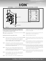
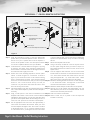
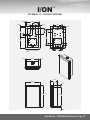
USER MANUAL • 5 • IN-WALL MOUNTING INSTRUCTIONS USING RAILS
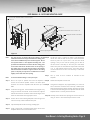
Mounting Rail
Level to this line
12.000
11.000
Drill 250" hole or use drywall anchor
Drill .250" hole or use drywall anchor
Hole for screw to hold mounting rails
.250" diameter
Not required for mounting with drywall anchors
3.250
Hole for screw to hold mounting rails
.250" diameter
Not required for mounting with drywall anchors
8.250
9.750
5.000
Drill .250" hole or use drywall anchor
Drill .250" hole or use drywall anchor
17.500
15.250
CUTOUT INSIDE THESE LINES
Hole for screw to hold mounting rails
.250" diameter
Not required for mounting with drywall anchors
1/4" Hole
Hole for screw to hold mounting rails
.250" diameter
Not required for mounting with drywall anchors
5.000
8.250
Cutout inside these lines
3.250
Drill .250" hole or use drywall anchor
Drill .250" hole or use drywall anchor
Figure 5-a
Figure 5-b
I/ON inwall mounting template 4/27/07
#10-32 -1-3/4" Flat Head Phillips Machine Screw
ION template for mounting
inwall 4/18/07
#10-32 x 2" Pan Head Phillips Machine Screw
Figure 5
I/ON can be mounted in drywall using either the supplied wooden Step 6 Using a drywall saw, cut out the drywall on the inside of the
rails or the supplied drywall anchors (mounting instructions for
template marked “Cut out inside these lines”.
when using drywall anchors is located on page 7). The rails are more
appropriate when the drywall is warped.
Step 7 Remove the template from the wall
Note: I/ON can only be mounted in a wall where there are no electrical
wires, pipes, or bracing in the wall.
Step 8 Slide the mounting rails in the drywall and secure it to the
wall using the four flat head #10 Phillips head machine
Mounting I/On in wall using supplied rails:
screws. Screw these in the wall so the head is below the
Step 1 Using the information on page 5, select the approximate
surface.
position where you want the speakers located. You will also
have to run a pair of speaker wires from the amplifier or Step 9 Locate the speaker wire in the wall. To prevent the wire from
receiver to speaker location. The metal push terminals on
falling into the wall cavity, you may want to attach the wire to
I/ON are compatible with the wires up to #8 AWG.
the studs using a plastic wire clamp (not supplied).
Step 2
Step 3
Locate the studs. The best method for doing this is by using Step 10 Using the wire strippers, strip approximately 1/2 inch from
an electronic stud finder. Follow instructions supplied with
each of the wires. Insert the wires in the top or bottom push
the stud finder to locate the center and the edges of the stud
terminals observing the proper polarity, where the wire going
and mark them with a light pencil mark.
to the red terminal I/ON goes to the positive terminal on the
amplifier which is normally the red terminal.
Position the in-wall mounting template between the studs
so drywall cutout area clears the studs on both sides. If the Step 11 Carefully slide the I/ON into the opening and secure to
cutout interferes with the stud locations you will have to shift
the rails using 6- #10-32 X 2” pan head Phillips machine
the location of the speaker to clear the studs.
screws.
Step 4 Once the template is clear of the studs; tape it to the wall
using masking tape. Using a level, confirm that template is
plumb and level. Readjust if necessary.
Step 5
Drill ¼” holes in the 10 locations as indicated on the
template.
Page 6 • User Manual • In-Wall Mounting Instructions Using Rails