1
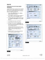
Fault Code Check
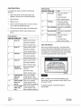
Blink Code Chart
Use constant power activation to perform the following fault
Blink Code Problem Area
Action
14
Verify correct electrical
code check.
1.
Power Supply
Apply constant power to the ECU /dual modulator valve
installation.
assembly for more than one, but less than five seconds.
Check power supply.
2.
Remove the power.
3.
Reapply the power.
4,
Check the trailer ABS indicator lamp on the side of the trailer.
Perform necessary repairs.
15
ECU Failure
If code
16
Find the fault on the chart and perform the necessary repairs.
6.
After performing the necessary repairs, repeat the end of
continues, contact
Meritor WABCO for assistance.
The fault code will be displayed three times.
5.
Verify correct installation.
SAE
J1708 Failure
Internal failure, contact Meritor
WABCO.
17
SAE
J2497 Failure
line test.
Internal failure, contact Meritor
WABCO.
18
Generic I/O Failure
Blink Code Chart
Verify correct electrical
installation.
Blink Code
Problem Area
Action
3
Sensor BU1
Determine sensor location.
Check power supply.
Perform necessary repairs.
Check sensor installation.
4
Sensor YE1
Perform necessary repairs.
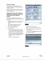
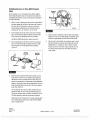
Trailer Identification
Determine sensor location.
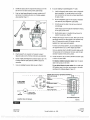
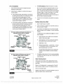
After ensuring the Enhanced Easy- StopTM trailer ABS has been
Check sensor installation.
correctly installed, attach the ABS indicator label included with the
ECU
Perform necessary repairs.
5
Sensor BU2
/single modulator valve assembly to the trailer. Generally, this
will be applied near the ABS trailer indicator lamp. Figure 28. Refer
Determine sensor location.
to the vehicle specification sheet for the correct location.
Check sensor installation.
Perform necessary repairs.
6
Sensor YE2
NOTICE:
Determine sensor location.
If the ABS indicator lamp
comes on and stays on when you
apply the brakes to a moving vehicle,
the trailer ABS is not working properly.
The ABS must be serviced as soon as
possible upon completion of your trip to
ensure full anti -lock braking capability.
Check sensor installation.
Perform necessary repairs.
7
External ABS
Verify correct electrical
modulator valve
installation.
Check power supply.
7'P -95172
Perform necessary repairs.
9
10
11
Rev. 4/98
4005501a
Internal modulator
Verify correct installation.
failure, inlet
If
valve #2
Meritor WABCO for assistance.
NOTE:
Internal modulator
Verify correct installation.
supervisor know. Labels are available from Meritor WABCO. Ask for
failure, inlet
If
valve #1
Meritor WABCO for assistance.
Internal modulator
Verify correct installation.
failure, outlet
If code
valve
Meritor WABCO for assistance.
Figure 28
code continues, contact
If
this label is not included with the assembly, let your
part number TP- 95172.
code continues, contact
For additional assistance, contact Meritor WABCO at
800 -535 -5560.
continues, contact
TP -20214
Revised 10 -05
Page 20
(16579/22882)
Copyright ArvinMeritor, Inc., 2005
Printed in USA
PDF compression, OCR, web optimization using a watermarked evaluation copy of CVISION PDFCompressor