1
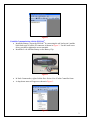
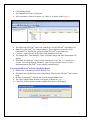
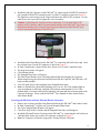
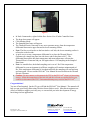
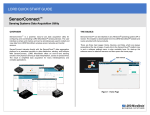
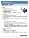
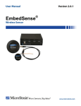
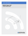
Quick Start Guide
EH-Link™ Energy Harvesting Wireless Sensor Node
Version
• EH-Link™ firmware 1.07
• USB Base Station firmware 2.09
• Node Commander® software 2.3.0
Starter Kit
The EH-Link™ starter kit contains:
• EH-Link™ Energy Harvesting Wireless Sensor Node
• USB Base Station with Antenna
• Thermal Electric Generator (TEG)
• Solar Demo Board
• Node Commander® Software and Manuals CD (Windows® XP, Vista, 7)
• 9 volt Alkaline Battery
• Battery Clip
• EH-Link™ 1000 ohm Tester Board
• 1000 uF Capacitor
• Small Screw Driver (for green terminal blocks)
Software Installation
• Insert the Node Commander® software CD into your CD-ROM drive and follow the onscreen instructions to install the software.
• Launch Node Commander® software.
• The Node Commander® Main screen will appear as shown in Figure 1.
Base Station Installation
• Install the antenna on the USB Base Station.
• Plug the USB Base Station into any USB port on your PC.
• The blue LED on the Base Station will illuminate continuously.
• After a moment Node Commander® will recognize the Base Station and display it as Base
Station Com X in the Controller frame as shown in Figure 1.
• Note: The X, as shown in the figure, indicates the communication port number to which
the Base Station has been assigned. In our example we see communication port 16.
1
Figure 1
Establish Communication with the EH-Link™
• Install the Battery Clip on the EH-Link™ by connecting the red lead to pin 9 and the
black lead to pin 10 on the P2 connector as shown in Figure 2. Use the small screw
driver provided to tighten the screw terminals.
• Install the 9 volt Alkaline Battery on the Battery Clip.
Figure 2
•
•
In Node Commander®, right-click the Base Station Com X in the Controller frame.
A drop-down menu will appear as shown in Figure 3.
Figure 3
2
•
•
•
Click Monitor Mode.
The Sampled Data frame will appear.
After a moment, a Node will appear, e.g. Node 10, as shown in the Figure 4.
Figure 4
•
•
•
•
•
The Node is the EH-Link™ and in our example we see an EH-Link™ with address 10.
Note: Every EH-Link™ has a unique address. These addresses are used by Node
Commander® to identify and operate multiple EH-Link™ at the same time.
Click the + sign to the left of the Node in the Sampled Data frame.
The Sample Rate, Total Samples, Timer Tick (time stamp) and other information will
appear.
By default, the EH-Link™ comes with its sample rate set at 1 Hz, i.e. 1 sample per
second. You will see that the Channel 1 value is being refreshed every 1 second,
indicating that the EH-Link™ is successfully communicating.
Powering the EH-Link™ with the Solar Demo Board
• Remove the 9 volt battery from the Battery Clip.
• Disconnect the red and black leads of the Battery Clip from the EH-Link™ and set these
aside.
• In Node Commander®, click the red X on the Sampled Data frame.
• The Close Sampled Data Window will appear as shown in Figure 5.
• Click Exit, Nodes Continue and the Sampled Data frame will disappear.
Figure 5
3
•
•
Install the 1000 uF Capacitor on the EH-Link™ by connecting the POSITIVE terminal to
pin 9 and the NEGATIVE terminal to pin 10 on the P2 connector as shown in Figure 6.
The light blue vertical stripe on the Capacitor denotes the NEGATIVE terminal. Use the
small screw driver provided to tighten the screw terminals.
Caution: 1) Discharge the Capacitor before connecting. 2) You must observe the
polarity of the Capacitor; otherwise unwarranted damage to the EH-Link™ may result. 3)
Inadvertent shorting of the charged Capacitor when connected to the EH-Link™ may
result in unwarranted damage to the EH-Link™.
Figure 6
•
•
•
•
•
•
•
•
Install the Solar Demo Board on the EH-Link™ by connecting the black lead to pin 1 and
the red lead to pin 2 on the P2 connector as shown in Figure 6.
In Node Commander®, right-click the Base Station Com X in the Controller frame.
The drop-down menu will appear.
Click Monitor Mode.
The Sampled Data frame will appear.
The Solar Demo Board is now collecting ambient light and charging the Capacitor.
When enough energy has been harvested and stored in the Capacitor, the EH-Link™ will
begin sending samples.
You will again observe this sampling in the Sampled Data frame.
Note: As stated before, the default sampling rate is set at 1 Hz. If the ambient light in
your environment is sufficient, sampling will continue uninterrupted at 1 Hz. If the
ambient light is less than sufficient, the sampling will start and stop and start again as the
Capacitor recharges. Please read the EH-Link™ User Manual for more details on the
Solar Demo Board.
Powering the EH-Link™ with the Thermal Electric Generator
• Remove the Capacitor and the Solar Demo Board from the EH-Link™ and set these aside.
• In Node Commander®, click the red X on the Sampled Data frame.
• The Close Sampled Data Window will appear.
• Click Exit, Stop Nodes Continue and the Sampled Data frame will disappear.
• Install the Thermal Electric Generator on the EH-Link™ by connecting the red lead to pin
3 and the black lead to pin 4 on the P2 connector as shown in Figure 7.
• Note: No Capacitor is needed to support the Thermal Electric Generator.
4
Figure 7
•
•
•
•
•
•
•
•
•
In Node Commander®, right-click the Base Station Com X in the Controller frame.
The drop-down menu will appear.
Click Monitor Mode.
The Sampled Data frame will appear.
The Thermal Electric Generator is now set to generate energy from the temperature
differential between its upper fins and its lower mounting surface.
Note: The fins are referred to as the heat sink or cold side; the lower mounting surface is
referred to as the hot side.
A quick way to create a temperature differential is to place the Thermal Electric
Generator on a simple hot plate, hot side down, and set the plate to 40°C. The
differential between the hot plate temperature and room temperature will start the
Thermal Electric Generator and you will again observe 1 Hz sampling in the Sampled
Data frame.
Note: As stated before, the default sampling rate is set at 1 Hz. If the temperature
differential in your environment is sufficient, sampling will continue uninterrupted at 1
Hz. If the temperature differential is less than sufficient, the sampling will start and stop
and start again. Please read the EH-Link™ User Manual for more details on the Thermal
Electric Generator.
Caution: Do not connect (or disconnect) the TEG to the EH-Link™ when it is harvesting
energy. Allow the temperature of the hot side and the cold side to equalize before you
connect (or disconnect) the TEG. Unwarranted damage may result to the EH-Link™.
Congratulations!
You are off and running! On the CD you will find the EH-Link™ User Manual. The manual will
help you put your Energy Harvesting Wireless Sensor Node to work. MicroStrain engineers are
always available to support you in any way we can and aid you in the development of energy
harvesting wireless applications.
8501-0012 rev. 003
Copyright © 2011 MicroStrain, Inc.
MicroStrain, Inc.
459 Hurricane Lane, Unit 102
Williston, VT 05495 USA
www.microstrain.com
ph: 800-449-3878
fax: 802-863-4093
[email protected]
5