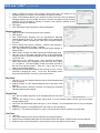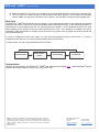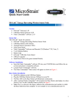
1
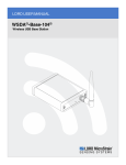
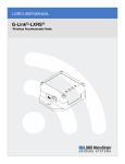
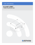
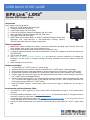
LORD QUICK START GUIDE IEPE-Link™-LXRS® Wireless IEPE Sensor Node Components Here’s what you need to get started: ™ ® 1. IEPE-Link -LXRS Module (PN: 6316-0010) 2. 2.4 GHz Antenna (PN: 9010-0133) 3. 9 VDC Power Supply (PN: 9011-0009) 4. 4 Piece Universal Power Supply Plug Adapters (PN: 9011-0022) ® 5. Node Commander Windows Software CD (PN: 8200-0013) 6. Quick Start Guide (PN: 8501-0053) ® ® 7. WSDA -Base-102/104 Base Station or WSDA -1000/RGD Wireless Sensor Data Aggregator (PN: 6307-1021/1041 or 6314-0050/1050) including antenna, communication cable and power supply, as applicable. Figure 1: IEPE-Link™-LXRS® Module Software Installation 1. IMPORTANT: Before installing this software, insure that the Windows Operating System Service Pack is the latest available; older versions may cause installation errors. ® 2. Insert the Node Commander software CD into the host computer’s drive. 3. An AutoPlay window will appear; click Run AUTORUN.EXE. If it does not, navigate to the drive and double-click AUTORUN.EXE. 4. The CD menu will appear. 5. Click Install the Node Commander Software Suite and follow the on-screen instructions to complete the installation. You will receive a message indicating successful installation and may be asked to restart the computer. 6. When completed, remove the CD. Hardware Installation 1. 2. 3. 4. 5. ™ ® Turn the IEPE-Link -LXRS module OFF (switch down). ™ ® Install the antenna on the antenna connector of the IEPE-Link -LXRS module. Tighten hand tight. Select appropriate power supply plug adapter for local electrical service and install on 9 VDC power supply. ™ ® Plug the barrel connector of the IEPE-Link -LXRS power supply into the power receptacle on the module. Plug the other end of the power supply into the appropriate electrical outlet to activate charging of the IEPE™ ® Link -LXRS internal rechargeable battery. 6. Observe that the Charging LED is red, indicating that the battery is charging. When the Charging LED turns ™ ® green, the IEPE-Link -LXRS module is fully charged and ready for use. When charged, disconnect the ™ ® power supply from the IEPE-Link -LXRS module. ® 7. Install the WSDA antenna, communication cable and/or power supply as appropriate, and connect to computer. Accelerometer and Accelerometer Cable 1 ™ ® The IEPE-Link -LXRS supports all single channel IEPE accelerometers through a 10-32 coaxial female connector. An example IEPE accelerometer is the Dytran Model 3256A2. Its measurement range is +/-50g with reference sensitivity of 100mV/g, and it has a 10-32 female connector. An example IEPE accelerometer cable is the Dytran Instruments Model 6013A03. It is a 36 inch (91 cm) mini coaxial cable with 10-32 male connectors on both ends. ™ ® Connect the IEPE accelerometer to the cable and connect the cable to the IEPE-Link -LXRS . Tighten hand tight. IEPE-Link™-LXRS® Quick Start Guide Establish Communication ® 1. Launch Node Commander software and the Main window will appear. ® 2. The WSDA will appear as Base Station Com X in the Controller frame; in our Figure 2 example, we see Base Station Com 44; this indicates that ® communication is established with the WSDA . 3. Right-click Base Station Com 44 and a drop-down menu appears. 4. Click Add Nodes. 5. Click Node Discovery and the Node Discovery window appears (Figure 3). ™ ® 6. Turn the IEPE-Link -LXRS module ON (switch up) and Node X will appear in the tree under Base Station Com 44; in our Figure 4 example we see Node 75; this ™ ® indicates that communication is established with the IEPE-Link -LXRS . 7. Click Stop and the Node Discovery window disappears. 8. Click the + sign to the left of Node 75 and the Model, Options, Serial Number, Firmware Version, Memory Full (amount of datalogging storage consumed), and Num Triggers (number of stored datalogging sessions) will be displayed (Figure 5). Configure Node 1. 2. 3. 4. 5. 6. 7. 8. 9. 10. 11. 12. 13. 14. 15. 16. 17. Figure 2: Base Station Comm 44 Figure 3: Node Discovery window Figure 4: Node 75 Right-click Node 75 and a drop-down menu appears. Click Configure. Click Configure Node and the Node Configuration window appears (Figure 6). Click the Channels tab. Click the Channel Enabled checkbox for Channel 1 to enable it; the IEPE accelerometer is on this channel. Click the … (ellipsis) button in the Configure column for Channel 1 and the Channel Configuration window appears (Figure 7). Figure 5: Info Tree Select Acceleration in the Class drop-down. Select G in the Units drop-down. Click the Edit Presets button and the Edit Presets window appears (Figure 8). Enter a title, e.g., our accelerometer has a serial number of 8088. We enter 8088. Enter the mV/G Sensitivity value that is provided on the calibration sheet of your particular IEPE accelerometer. For our example we are using a +/-50g Dytran Model 33256A2, referred to above. We are given a Sensitivity value of 97.7 mV/G. Enter 97.7 in the mV/G textbox. Click the Add Preset button and the preset is saved. Note: These Figure 6: Node Configuration window Presets now become selectable for future configurations. Click Close button and the Edit Presets window disappears. Select 8088 in the mV/G drop-down. Select a Low Pass Filter Cutoff setting in the drop-down. As a rule of thumb, select a Low Pass Filter Cutoff setting that is no more than ½ of your sample rate. In our example, we are expecting to measure vibration up to 5000 Hz. We will be setting our sampling rate at 10000 Hz; therefore select a Low Pass Filter Cutoff setting of 5000 Hz. Click OK and the Channel Configuration window disappears. Click Apply and the calibration coefficient is written to the module’s non-volatile memory (EEPROM). Configure Sampling 1. Click the Synchronized Sampling tab (Figure 9). 2. Click the Burst Sampling checkbox to enable it. 3. Select a sample rate in the Sample Rate drop-down. In our example, we are expecting to measure vibration up to 5000 Hz; therefore select a sample rate of 10000 Hz. Figure 7: Channel Configuration window 2 IEPE-Link™-LXRS® Quick Start Guide 4. Select a Duration Per Burst in the up/down number scroll; this is the duration of the sampling session in seconds; for our example, we select 5 seconds. 5. Select a Time Between Bursts in the up/down number scroll; this is the time between sampling sessions; for our example, we select 2 minutes; the system requires a certain minimum time for the data to transmit; 2 minutes is the minimum available for this particular sampling configuration. 6. Click Apply. 7. Click OK and the Node Configuration window disappears. Figure 8: Edit Presets window Sampling Session 1. Right-click Node 75 and a drop-down menu appears. 2. Click Sample. 3. Click Synchronized Sampling and the Synchronized Sampling window appears (Figure 10). Our example Node 75 is reported with an In Network status, indicating the node and its sampling settings are found. 4. Use the default fault options: Lossless = enabled, High Capacity = disabled, Enable Beacon on Start = enabled. 5. Click Apply Network Configuration and the node status changes to Ready to Start. 6. When ready to sample, click Start Sampling and sampling will begin. 7. Click the red X in the upper right hand corner of the Synchronized Sampling window, the window disappears, and the Sample Data tab comes into view. 8. Depending on the sampling setup, many seconds will transpire before data arrives and is displayed in the Data Grid View (Figure 11). Be patient. The initial display of data will indicate success of the first burst sampling session. Click the + sign to the left of the Node to get sampling statistics. 9. Subsequent burst sampling sessions will continue to occur until you intervene by stopping the node. To be clear: No sampling occurs during data transmission; see Burst Cycle section below. Figure 9: Synchronized Sampling tab Figure 10: Synchronized Sampling window Stop Node 1. Click the red X of the Sampled Data tab and the Close Sampled Data window appears. 2. Right-click Node 75 in the Sampled Data tab and a drop-down menu appears. 3. Click Stop All Nodes, and after a moment, a message box will appear indicating sampling has stopped. Display Data 1. Click the View Mode drop-down in the Sampled Data tab and select Figure 11: Data Grid View Graph. 2. The view will change to an XY graph; select Node 75 in the Available Nodes column and the previously sampled data will plot. 3. Click the X-Axis Width drop-down and select 1, as an example. This will spread the plot out for more detailed analysis. 4. Right-click anywhere in the graphing area and a pop-up menu will appear. 5. Select Pan. The pointer will change to a ‘hand’. Click and hold at an area of interest to pan the data. View Data 6. 7. 8. 9. 3 Click File. Click Explore Data Directory and the Data Directory window appears. Double-click the Sampled Data folder and all Session folders will appear. Session folders are time stamped. Select the most recent time stamp to view the latest session and double-click the folder. IEPE-Link™-LXRS® Quick Start Guide 10. Select the data file for your node; in our example we are selecting Node75.CSV; double-click to open the CSV. 11. The Time and Tick columns should be used to identify each burst sample in your multiple burst sampling session. Note: You may have to format the Time column to “h:mm:ss.000” to observe human-readable time. Burst Cycle ™ ® The IEPE-Link -LXRS operates as shown in the diagram. Once configured and launched, the node waits in low power mode while the real time clock (RTC) counts the seconds until the first scheduled burst. In the default configuration, 15 seconds prior to the scheduled burst time, the accelerometers are charged. At the scheduled burst time, the node starts sampling for the duration of the burst period selected by the user. Once sampling is completed, the data is transmitted. When transmission is complete, the node returns to low power mode, and again counts the seconds until its next scheduled burst. If a node is configured to burst every minute, the node will start sampling at the top of the minute. If a node is configured to burst every hour, the node will start sampling at the top of the hour. To stop the node, the user must send the Stop Node command. Low Power Mode Accelerometers Turn On Burst Sampling Transmit Data Congratulations You are up and running! The IEPE-Link™-LXRS® user manual can be found here. LORD MicroStrain® support engineers are always available to support you in any way we can. 4 Copyright © 2014 LORD Corporation 3DM-GX4-45™, IEPE-Link™, 3DM-RQ1™, Strain Wizard®, DEMOD-DC®, DVRT®, DVRT-Link™, WSDA®, HS-Link®, TC-Link®, G-Link®, V-Link®, SG-Link®, ENV-Link™, Watt-Link™, Shock-Link™, LXRS®, Node Commander®, SensorCloud™, Live Connect™, MathEngine®, EH-Link®, 3DM®, FAS-A®, 3DM-GX3®, 3DM-DH®, 3DM-DH3™, MicroStrain®, and Little Sensors, Big Ideas® are trademarks of LORD Corporation. 8501-0053 rev 002 LORD Corporation MicroStrain® Sensing Systems 459 Hurricane Lane, Suite 102 Williston, VT 05495 USA www.microstrain.com ph: 800-449-3878 fax: 802-863-4093 [email protected] [email protected]