1
TIP-VBY1HS-DS
5.2. Receiver Core
The Receiver core has a symmetrical function with the Transmitter core.
Each Main Links receives the data from the transmitter side through the High-speed serial
transceiver and regenerates the allocated data with decoding, de-scrambling, packet data
un-mapping, and de-framing. In the end, these framing data from the Main Links combined to
regenerate the original stream of video data and control signals.
The Receiver core also has a training function for the link start up with the transmitter side while
generating the Hot plug and CDR Lock status signal.
In order to check the quality of the high-speed serial data lines, the Receiver core has an operation
mode in which they act as the bit error tester (BET) called “Field BET mode”.
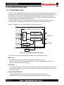
Figure 5.2 shows the function block diagram of the Receiver core.
Figure 5.2 Receiver Core Block Diagram
The Receiver core can be classified into the main function blocks as follows.
Main Link
The Main Link is a main function block provided as the netlist file (.ngc) .
Main Link consists of unpacker, de-scrambler, decoder, de-serializer, and receiver link monitor.
Each data lane has own Main Link block.
De-formatter
De-formatter matches the skew of the packet data from the Main Links and regenerates the
user-driven stream of video data and control signals from the allocated data in the Main Links.
Clock / Reset Generator
This block makes all clocks and reset signals required in the Receiver core from the recovery
clock from the transceiver in Main block.
Appropriate frequency clocks adjust the rate difference between the function blocks and
regenerate the pixel clock of the Transmitter side.
Rev1.00
8