1
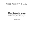
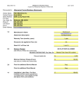
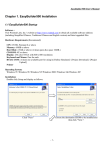
D. A. I. S.
Digital Audio Interconnection System
User Manual
Audio-Service Ulrich Schierbecker GmbH
Schnackenburgallee 173
22525 Hamburg
Tel.:049 40 / 851770-0
Fax.:049 40 / 8512764
e-mail: [email protected]
internet: http://www.audio-service.com
V 2.10
Contents
3
Introduction
4
Safety Information
5
Installation of Hardware
6
Front and Rear Panel Layout
7
Installation of Software and Operating Instructions
8
D.A.I.S. Set Up
9
View of the Function Bar
10
Basic Functions
11
Patchbay Structure
12
The Status Bar
13
Synchronisation
14
Schematic Example
15
Specification
16
Declaration of conformity
Introduction
Congratulations on the purchase your D.A.I.S. !!!
The D.A.I.S. is in principle a patchbay,the patching however is achieved electronicly and dispenses
with the need for patchcords.The setting of cross-over points is comfortably enabled through an x/y
matrix using a Windows 95/98/NT or Mac (Soft PC) platform.
Further main features of the D.A.I.S. are signal distribution,and the format conversion of digital input
signals.
The system operates using the already widespread Yamaha CD8 series interface cards (02R and
03D).Supported formats are AES/EBU, ADAT, TDIF (Tascam) and Y2 Yamaha (Optional AD/DA
converter)
The D.A.I.S. router is controlled by a routing matrix software via RS422,RS232 interfaces (Com
Port) or via midi connection.
Copyright c 2000
Audio Service Ulrich Schierbecker GmbH
Schnackenburgallee 173
22525 Hamburg
Germany
The duplication of this manual requires the previous written appproval of the publisher
3
Safety information
Please carefully read the following safety information before commencing installation of the
D.A.I.S..
Failure to follow the listed safety information may lead to severe or even fatal injury
Attention! This appliance must be earthed.The power supply must always be disconnected at
the mains before any installation work is carried out.
Please follow these precautions, to avoid accidents or injury, or any damage to this appliance or other
appliances or property.
!
!
!
!
!
!
!
Take care to avoid contact with any sharp metal edges or protrusions.
The D.A.I.S. is sensitive to static charge.Before installation work commences
you are advised to discharge any static electricity from your body by first
touching the metal casing of the D.I.A.S.
The equipment contains no user servicable components,do not at any time
attempt to open the casing.
Maintenance or repair should only be carried out by suitably qualified persons.
Ensure that the equipment receives adequate ventilation from above and below.
Should the D.I.A.S. be mounted into a rack containing heat emmiting devices
such as amplifiers,power supplies etc,we strongly recommend that the rack is
fitted with cooler fans,in order to reduce the amount of residual heat within the
rack.
By rack mounting be sure to use the delivered front and rear mounting brackets.
Do not expose the D.I.A.S. to moisture or operation in humid conditions,this
may lead to a malfunction,or indeed severly damage the equipment.
Audio-Service GmbH cannot be held responsable for loss of data, damage to property
or any injuries, which may occur through improper operation or handling
Upon delivery please inform your dealer or Audio-Service GmbH, Hamburg,
immediately over any transportation damage, shortfalls,or any apparent
malfunction of the equipment.
4
Installation of Hardware
Unpacking
Please check the D.A.I.S. for any transportation damage and for shortages in the items of
hardware or software.Register any damage or shortfalls immediately with your supplier.
It is advisable to retain the original packaging, it is the best possible way to protect the
equipment during future transportation.The delivery should consist of the following items,
! D.A.I.S. Rack & Mounting Hardware
! System Software ( 1 x 3,5" Disc )
! P C Connecting Cable LS 232 ( 5 Meter )
! Owners Manual & Installation information
Rack Mounting
Should you propose to install the D.A.I.S. into a rack, it is of the upmost importance that
the supplied front and rear mounting brackets be used.
Please note that the ambient temprature should not rise to over 35°C.This limit will be
exceeded in a non ventilated rack, especially when the rack contains other heat emmiting
devices (Amplifiers, etc)
Installation Precautions
! Before beginning the installation,switch off all power to the main unit and connected
peripherals,disconnect all units from the main power supply.
! Remove all interconnecting cables between the main device and the peripherals (leaving
power cables attatched while working on the units will lead to the risk of elecktrocution
and
interconnection cables may interfere with the installation work)
! Module components can be damaged by electrostatic discharges,be sure to drain off any
such charges from both body and clothes before starting the installation
! Do not touch module components,board curcuitry,and metallic leads during installation.
! Take care to avoid dropping screws or other foreign matter into the equipment during the
installation work.Should such items fall into the unit during installation be sure to remove
such
items before reassembly and power up.Starting the unit with such items inside could
lead to the risk of malfunction during operation,or even unrepairable damage.
Installation
! Using the supplied cabel (LS232) connect your computer with the D.I.A.S.( Normally
over the Com 2 port as Com 1 is normally reserved as the mouse port).
! Connect the the Interface Cards (CD 8) to the corresponding periphery as required.
! Power up the computer and the D.A.I.S.
5
D.A.I.S. Frontpanel
COM Led
Lock Led
Ready Led
Fuse
Power Led
Powerswitch
D.A.I.S. Rearpanel
6
Installation of Software and
Operating Instructions
The D.A.I.S. system software is included in the delivery package and consists of one 3,5" floppy
disc.In order to operate the D.A.I.S. under a Windows platform you will require the following
hardware and software.
! A Pentium processor
! 32 megabytes (MB) of RAM.
! Windows 95/98 or NT system software.
! 3,5" floppy disc drive
! Mouse
Software Installation
Insert the 3,5" floppy disc into your disc drive and start the set up program (A:\setup)The D.A.I.S.
installation guide will be displayed on your monitor screen ,and will guide you through the installation
proccedure.
(NB towards the end of the installation proceedure you will be asked wether or not to the
update %%comct32dll$$
%%
$$ should be installed,this data is only required by users working under a
Windows NT platform,users working under Windows 95/98 should answer this question with
a %% No$$
$$).Once the installation proceedure is completed the D.A.I.S. program may be accessed in
the Windows start menu.
7
D.A.I.S. Set Up
Before commencing work with the the unit must first be configured.The main PC and Card
configurations are carried out in the Hardware window.
The hardware window contains information on,and allows access to the following settings.
! The field Port enables selection of the desired PC input port (usually Com 2)
! The field Device indicates the number of the device to be configured.
! The field Master Sync indicates the master syncronisation source and is coupled to two
display fields,the first indicating the current status Locked or Unlocked,the second field
displays the Sample Rate.
! The Reset Behaviour feature in the Set Hardware field is acktivated by clicking in the
display box.In the default mode (crossed is on) the D.A.I.S. will accept information from
the PC once the Go Online button is activated, and will configure itself accordingly,in the
off
position the proceedure is reversed and the PC will "read " information from the
D.A.I.S.
! The button Auto Set enables the automatic recognition of up to14 interface cards.(NB cards
17 - 20 must be set up manually)
! The button Set is used when confirming manual configurations.
! The D.A.I.S. seriel number and the hardware version number are displayed in the top right
hand corner of the hardware window.
Initial Set Up
The first step following the manual assembly works (control card installation etc) is to allow the
D.A.I.S. to recognise the installed control cards,to accomplish this proceed as follows,
! Enter the Hardware window and in the Reset Behaviour field set the Set Hardware
feature to default (on).
! Click on the Auto Set button,and the system will recognise and allocate a "slot" to each
of up to 14 Interface cards.Any unoccupied slots will be shown in the display as None
(please
remember cards 17 - 20 are
optional and must
be set up manually).
8
View of the Function Bar
9
Basic Functions
A total of fourteen Yamaha CD8 interface cards may be loaded into the D.A.I.S. Each card controls
eight inputs and eight outputs.A patchbay size of fifty six by fifty six stereo channels is obtainable when
the D.A.I.S. is fully loaded.
The Basic Matrix display will appear on start up of the software.The Windows Toolbar is situated in
the uppermost display.Immediately below this the D.A.I.S. Basic Functions Toolbar is displayed,the
functions are accessed through a mouse click on the
a
ppropriate symbol (e.g. Open,save,undo,redo,zoom
in
,zoom out etc).
The D.A.I.S. File Path is situated on the left hand side of the screen (the file path can be blended in
or blended out using the toogle tree bar control) displayed here are the various patchbays,and
configurations available to the operator.After "naming" and storing a new or ammended patchbay
configuration,it will be displayed here under its "name"
Next to the Audio Service logo are the displays for Master Sync and the Sample Rate.
The Matrix or Patchbay is situated on the center to right hand side of the screen.All Matrix Inputs
are displayed in the vertical axis (to the left of the Matrix), all Matrix Outputs are displayed in the
horizontal axis (above the Matrix).The inputs and outputs can be "named "by
clicking in the these fields.
A Crosspoint is set by a "double click" on the appropriate matrix square,the matrix square will turn
"yellow" in colour.It is also possible to set several crosspoints by "dragging" the horizontal or diagonal
matrix squares, during this operation the matrix squares will turn"green" until the revised set up is
confirmed using the "switch all presets" button at this stage the relevant matrix squares will turn
"yellow".Crosspoints may be deleted using the "switch all off" button,in this case an appropriate
"safety screen" will appear requesting confirmation of this acktion.
The Matrix Status is permanently displayed
Matrix Display and indicates the number of,
! Off connections
! Pre off connections
! On connections
! Pre on connections
in the top left hand corner of the
10
Should the monitor screen be unable to accomodate the entire D.A.I.S. display,the respective position
in the patchbay is shown parallel to the mouse cursor (Tooltip).This Tooltip will be displayed with
contrasting background colours,a white background indicates that the cross point is free and has not
been allocated or set,a yellow background indicates that the crosspoint has been already allocated
in a syncronised patchbay.
The Matrix to screen ratio may also be adjusted using the Zoom in or Zoom out feature.
Data flow to the host computer is enabled by the Go Online
possible to set or delete online crosspoints at any time.
button.Naturally it is
Patchbay Structure
As mentioned previously the basic matrix is visable upon system start up.Up to twelve basic
configuration may be stored using the the Preset Memories (Shift plus F1 - F12).e.g,the settings for
the hardware controller,the sync card,the output settings etc.
A restricted matrix (View) display (eg to set up a control room matrix) is established as follows,
!
!
!
Select the first crosspoint with the right hand mouse key (define view start) the crosspoint
will be highlighted in blue.
Using the same procedure establish the second (end) crosspoint from the opposing matrix
axis (define view end).
When both points are defined, a menue will open in which a view "name" may be assigned.
A view may be further sub-divided into lots of sub-sections ( SETS) ,in which different
specified crosspoints are stored into the matrix.These sections can be reactivated from within
the file path through a double click on the respective set "name".
11
New matrix settings are enabled in the Status Bar menu Matrix,by selecting New Set in the drop
down menu.Once the new matrix set up is defined it should be named and stored by clicking on "OK"
The new set up will then appear in the tree bar field on the left-hand side of the monitor screen.All set
ups and views may be deleted from within the Matrix menu using the selections Delete View or
Delete Set. The Overwrite Set option enables the editing of existing matrix set ups.
General View of the Status Bar
As described above the D.A.I.S. status bar enables access to the special functions.Divers
commands are to be found under the menu File,for example Save,Open and Close.Under the
menu Edit the Undo and Redo functions are to be found.Under the View menu the three main
function fields Toolbar, Status Bar and Treebar can activated or de-activated as required, whilst
in the menu Matrix the Go Online, All Off, All Off,View and Set functions may be selected.
An important feature is to be found in the menu Options,under the option Settings in the drop
down menu the number of Undo Buffers can be adjusted in the General sub menu.The function
"Not losing the last set" is also to be found in this sub menu,activating this feature ensures that
actual settings will not be lost in the event of a system failure.
12
Synchronisation
The D.A.I.S. can function as either a Master or a Slave unit within a digital audio installation.In the
Master mode it is possible to switch between the internal Sample Fenquenzes of 44,1 Khz and 48
Khz.
When the D.A.I.S. is integrated as a Slave unit, one, of sixteen Syncronisation sources may be
selected by the user, either,
!
!
!
Word Clock Input.
AES Ref Input.
3 - 16, Channels 1 and 2 from each of the 14 Yamaha YGDAI interface cards.
The D.A.I.S. is in principle syncronised with the Yamaha YGDAI interface cards (CD8 series).That
is to say that all audio signals should be syncronised to each other,failure to observe this rule may lead
to audible clicks or distortion.
Format conversion and signal conditioning is only possible with these or the following interface cards,
!
!
Audio Service unsyncronised AES interface card (allows the connection of equipment with
different sample rates in a syncronised patch bay.(syncronised and unsyncronised Patchbay
in a D.A.I.S. system).
Amptec AES/EBU interface cards with an integrated sample rate converter.
Optical Warnings
The D.A.I.S. main screen also integrates a visual control of Interface card and Syncronisation status.
Should the set up of an Interface card change during operation,the relevant channel in the Matrix
display will be displayed with a Red background.
Should the Master Sync Mode go out of the Lock mode the Audio Service Logo will turn Red and
begin to blink.A mouse click on the logo will restore the display to its original status.
13
The following schematic represents a D.A.I.S. working as Slave to a Master DA-88 Recorder.
Technical Specification
Frame:
19" Standard Rack Mounting
4 HE
Sockets for 14 Single slot Cards or 4 Double slot Cards
Router:
72 x 72 Stereo Crosspoint Matrix
Total of 144 Channels
56 Inputs / Outputs (Yamaha YGDAI Interfaces)
16 Inputs / Outputs - Passive AES / EBU
Compatible YGDAI Cards:
Yamaha CD8-AES AES/EBU
25 Pin Sub-D 1H
Yamaha CD8-AT
ADAT Optisch
Toslink x 2 1H
Audio-Service CD8MYAT 24Bit ADAT Interface
1H
Yamaha CD8-TD II T-Dif II
25 Pin Sub-D 1H
Yamaha CD8-Y2
Yamaha Y2
25 Pin Sub-D 1H
Yamaha CD8-AE
AES/EBU
4x XLRm,4xXLRf 3H
Audio-Service CD8SDIF-2 Interface
2 x Sub-D 25 1H
Yamaha CD8-ADS AD Karte
8 x Klinke6,3 1H
Yamaha CD8-AD
A/D-D/A Karte
16 xKlinke6,3 3H
*(only in conjunction with an additional Power Supply)
AMPTEC CD8SRC AES/EBU mit SRC’s 25 Pin Sub-D 1H
Passive AES/EBU Cards:
Audio-Service AS-8P 4 x AES/EBU In / out 25pin Sub-D
Audio-Service AS-9P 4 x AES/EBU In / out 25pin Sub-D
for Slots 17-20
Sync:
Internal 44,1 Khz and 48 Khz
External Wordclock
BNC In / BNC Out
AES / EBU Reference
Sub D
Control:
Software Requirements:
Power Requirements:
Dimensions:
Weight:
RS 232, RS422, Midi.
Windows 95 / 98 / NT or MAC ( Soft PC )
95 - 240 Volts AC
19" x 4 HE x 50 cm
ca. 10 Kilogramm
1H
Teac,Tascam and TDIF are registered Trademarks of the Teac Corporation.
Alesis and ADAT are registered Trademarks of the Alesis Corporation.
Yamaha,02R,03D,CD8 and YGDAI are registered Trademarks of the Yamaha Corporation.
Windows 95,98 and NT are registered Trademarks of the Microsoft Corporation.
Audio Service Ulrich Schierbecker GmbH retains the right to change or alter any technical specification without prior notice.
Declaration of Conformity
Audio Service Ulrich Schierbecker GmbH
Stresemannstrasse 268
22769 Hamburg
Germany
declares under their sole responsibility that the product
D.A.I.S.
(Digital Audio Interconnection System)
to which this declaration relates, is in conformity with the following
standard(s) or other notmative document(s)
EN 55013/90 EN 55020/94 EN 6100-3-2/95
following the provision of the EMC directive.
89/336/EEC
Issued in Hamburg, the
Ulrich Schierbecker
General Manager