1
Operation Data Managing Software
PCWAY
User’s Manual
ARCT1F392E-7
2013.7
panasonic.net/id/pidsx/global
Safety Precautions
Read and understand this specifications, instruction manual, installation manual and catalog
to make proper use of the product.
WARNING
If critical situations that could lead to user’s death or serious injury is assumed by
mishandling of the product:
- Do not play the accompanying disk on an audio CD player or speakers of a personal
computer.
It could lead to the injury of your ears or the damage to the speakers due to mega volume.
Copyright / Trademarks
- You may use this software in accordance with the “Licensing terms for the software”.
- This manual and its contents are copyrighted.
- You may not copy this manual, in whole or part, without written consent of Panasonic
Industrial Devices SUNX Co., Ltd.
-Windows, Windows NT and Excel are registered trademarks of Microsoft Corporation in the
United States and other countries.
- Ethernet is a registered trademark of Fuji Xerox Co., Ltd. and Xerox Corp.
- All other company names and product names are trademarks or registered trademarks of
their respective owners.
PCWAY
PREFACE
We appreciate your purchase of our software product.
This “User's Manual” is published to tell beginners about setup
and operating outline of the product.
Please understand a content of this booklet very well to use
the product correctly.
In addition, see the online help of the product for details of the
way of use.
Would you please…
Tell us if you find something dubious or of errors in this manual
despite our heed to publication of the booklet as possible.
i
Table of Contents
1. Installation of PCWAY ............................................................. 1-1
1.1
System Configuration ................................................................................ 1-2
1.2
Version Up from Ver1.** or Ver2.** ............................................................ 1-4
1.3
Installing .................................................................................................... 1-5
1.4
Verify the Installing .................................................................................... 1-6
2. Overview - PCWAY .................................................................. 2-1
2.1
PCWAY Memory Area ................................................................................ 2-2
2.1.1 Explanation on the Relay ..................................................................... 2-2
2.1.2 Explanation on the Register ................................................................. 2-4
2.1.3 Explanation on the Event ..................................................................... 2-5
2.1.4 Explanation on the Trigger and the "informing" ..................................... 2-6
2.2
Basic operations of PCWAY ....................................................................... 2-9
2.3
Basic Specifications ................................................................................. 2-12
2.4
Module .................................................................................................... 2-13
2.5
Precautions ............................................................................................. 2-14
2.5.1 Operation Preferences ....................................................................... 2-14
2.5.2 Operations of PCWAY ........................................................................ 2-15
2.5.3 Trigger ............................................................................................... 2-16
2.5.4 Clipboard ........................................................................................... 2-17
2.5.5 Macro name ....................................................................................... 2-17
2.5.6 Special data register .......................................................................... 2-17
2.5.7 About the file name of Microsoft® Excel ............................................. 2-17
2.5.8 Application Startup ............................................................................ 2-18
2.5.9 Export function of Each Registering Module ....................................... 2-18
2.5.10 When you make the macro of the Microsoft® Excel ............................ 2-18
2.5.11 Others ................................................................................................ 2-18
ii
3. Overview - HARDWARE ........................................................... 3-1
3.1
Overview on Hardware ............................................................................... 3-2
3.2
When Connected by MEWNET-H ............................................................... 3-3
3.3
C-NET(RS232C) Connection ..................................................................... 3-5
3.4
Modem (Up To 64 Remote Regions) .......................................................... 3-8
3.5
Modem (Over 65 Remote Regions) .......................................................... 3-15
3.6
Not Connect ............................................................................................. 3-16
3.7
Error Reception ....................................................................................... 3-17
3.8
Ethernet(Local/Remote) Connection ........................................................ 3-21
3.8.1 Ethernet (Local) ................................................................................. 3-22
3.8.2 Ethernet (Remote) .............................................................................. 3-24
3.9
USB (GT32/GT05) Connection ................................................................. 3-25
4. Basic Operations of PCWAY ................................................... 4-1
4.1
Displaying and Operating PLC Data Information with Microsoft® Excel ...... 4-2
4.1.1 Outline of the Basic Procedures ........................................................... 4-2
4.1.2 Setting the cell information ................................................................... 4-5
4.1.3 Copying and pasting the cell information ............................................. 4-11
4.1.4 How to operate during the running of the monitoring ........................... 4-12
4.2
Saving PLC Information into the File ........................................................ 4-16
4.2.1 The file ............................................................................................... 4-16
4.2.2 Create a file and execute the processing ............................................ 4-19
4.2.3 Displaying the file data onto the Microsoft® Excel sheet ..................... 4-22
4.3
Booting Microsoft® Excel Macros Automatically ....................................... 4-25
4.3.1 What is a macro? ............................................................................... 4-25
4.3.2 Creating the Macro ............................................................................. 4-25
4.3.3 Register the macro which will start automatically ................................ 4-33
4.4
Turn on the Relay/Event at a Specified Time or at a Certain Interval ........ 4-34
4.4.1 Turn the Relay and Event to On at the Specified Time of the Specified
Day of the Week ................................................................................. 4-34
4.4.2 Turn the Relay and Event to On at a Certain Interval .......................... 4-35
4.5
Playing the Sound .................................................................................... 4-36
4.5.1 Procedures of the sound playing ......................................................... 4-36
iii
4.5.2 Create the WAV file ............................................................................ 4-36
4.5.3 Register at Sound Startup .................................................................. 4-36
4.6
Turn On the Event by the Changing of the Relay Information of the PLC .. 4-37
4.6.1 Watch the changing of the relay ......................................................... 4-37
4.6.2 Have PCWAY recognize the relay which will be watched as the link
relay .................................................................................................. 4-37
4.6.3 Perform the event startup ................................................................... 4-38
4.7
Managing the File .................................................................................... 4-39
4.7.1 Manage the file with the generation of the accumulating file ............... 4-39
4.7.2 Controlling Files Using the Microsoft® Excel Book Log ....................... 4-40
4.7.3 Saving Microsoft® Excel books as HTML ............................................ 4-41
4.8
Using the Public Phone Line .................................................................... 4-42
4.8.1 The Difference between Less than 65 and 65 or More Remote
Locations ........................................................................................... 4-42
4.8.2 When Thereare Less Than 65 Remote Regions .................................. 4-57
4.8.3 When There are More than 65 Remote Regions ................................. 4-71
4.9
Using the E-mail Function ........................................................................ 4-84
4.9.1 Overview ............................................................................................ 4-84
4.9.2 Sending the Error Status Information to the PC and the Cellular
Phone via E-mail ................................................................................ 4-85
4.9.3 Sending Equipment Status Information Periodically to the PC and the
Cellular Phone via E-mail ................................................................... 4-86
4.9.4 Inquiry on the Equipment Status from the PC and the Cellular Phone
.......................................................................................................... 4-87
5. Operations From the PCWAY Menubar .................................. 5-1
5.1
Cell Settings .............................................................................................. 5-2
5.1.1 Setting method ..................................................................................... 5-3
iv
5.2
Delete Cell Settings ................................................................................. 5-11
5.3
Copy Cell Settings ................................................................................... 5-12
5.4
Paste Cell Settings .................................................................................. 5-13
5.5
Set Cell Order .......................................................................................... 5-15
5.6
Run PCWAY ............................................................................................ 5-16
5.7
Exit PCWAY ............................................................................................ 5-17
5.8
Read PCWAY Settings Again ................................................................... 5-18
5.9
Start Monitor ............................................................................................ 5-19
5.10 Stop Monitor ............................................................................................ 5-20
5.11 Download Data ........................................................................................ 5-21
5.12 Update All Sheet Data ............................................................................. 5-22
5.13 Update Active Sheet Data ........................................................................ 5-23
5.14 Save Excel file ......................................................................................... 5-24
5.15 Save HTML File ....................................................................................... 5-25
5.16 Compile ................................................................................................... 5-26
5.17 Protecting the Sheet ................................................................................ 5-27
6. Registering - Module ............................................................... 6-1
6.1
Setting Operation Preferences ................................................................... 6-2
6.2
Character Change .................................................................................... 6-25
6.3
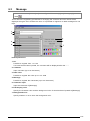
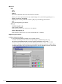
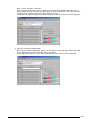
Message .................................................................................................. 6-31
6.4
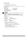
Operation Formula ................................................................................... 6-38
6.5
File Master ............................................................................................... 6-44
6.6
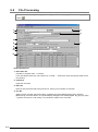
File Processing ........................................................................................ 6-50
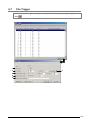
6.7
File Trigger .............................................................................................. 6-57
6.8
Event Startup ........................................................................................... 6-62
6.9
Weekly Timer ........................................................................................... 6-67
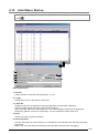
6.10 Interval Timer .......................................................................................... 6-71
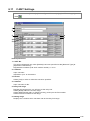
6.11 C-NET Settings ........................................................................................ 6-75
6.12 Auto Macro Startup .................................................................................. 6-79
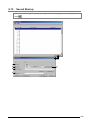
6.13 Sound Startup .......................................................................................... 6-83
6.14 Modem Support ....................................................................................... 6-88
6.15 Application Startup ................................................................................... 6-97
6.16 Connection No. ...................................................................................... 6-101
6.17 Ethernet Remote .................................................................................... 6-104
6.18 E-mail Setting ........................................................................................ 6-111
v
7. Overview List for Reference .................................................... 7-1
7.1
Notation method of the Memory area in PCWAY ........................................ 7-2
7.2
Use file name list ....................................................................................... 7-3
7.3
Incorporation macro name list .................................................................... 7-4
7.4
API Function for Event(V) Access .............................................................. 7-9
7.4.1 Obtaining the Status of the Specified Event Number (VC Function) ....... 7-9
7.4.2 Obtaining the Status of the Specified Event Number (VB Function) ..... 7-10
7.4.3 Changing the Status of the Specified Event Number (VC Function) ...... 7-11
7.4.4 Changing the Status of the Specified Event Number (VB Function) ..... 7-12
7.4.5 Obtaining the Status of All Events (VC Function) ................................ 7-13
7.5
Functions Upgraded in PCWAY Ver. 2.5 .................................................. 7-14
7.5.1 PCWAY macro auto record ................................................................. 7-14
7.5.2 Available for WR, WX, WY and WL devices ........................................ 7-14
7.5.3 Available for [Decimal point] ([Real number]) data .............................. 7-15
7.5.4 High-speed data communication ......................................................... 7-15
7.5.5 AND and OR with calculation functions ............................................... 7-16
7.5.6 Saving Microsoft® Excel books as HTML ............................................ 7-17
7.5.7 Enable/Disable selection for the connecting station No. during
PCWAY monitoring ............................................................................. 7-18
7.6
Upgrade items of Ver2.74 ........................................................................ 7-19
7.7
Upgrade items of Ver2.76 ........................................................................ 7-20
7.8
Upgraded items of Ver2.80 ...................................................................... 7-21
7.9
Upgraded items of Ver2.82 ...................................................................... 7-22
8. Appendix .................................................................................. 8-1
vi
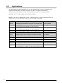
8.1
Applications ............................................................................................... 8-2
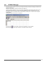
8.2
PCWAY Manager ....................................................................................... 8-3
8.3
PCWAY Utility ............................................................................................ 8-4
8.4
Concerning the copying of the system created with PCWAY ...................... 8-6
8.5
Back-up Utility ........................................................................................... 8-7
8.6
PCWAY Logger ......................................................................................... 8-9
8.7
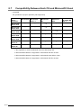
Compatibility Between Each OS and Microsoft® Excel ............................. 8-18
8.8
Compatibility Between PCWAY and Each OS .......................................... 8-19
8.9
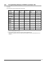
Correspondence Table between PCWAY and Microsoft® Excel ............... 8-20
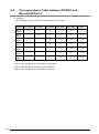
8.10 Correspondence Table between PCWAY and Programmable Controllers . 8-21
vii
viii
Chapter 1
Installation of PCWAY
1.1
System Configuration
The matters which are listed here, are what you have to prepare for besides of what is available
with the PCWAY package.
Before doing the installing, please be aware of what hardware and software you are using.
[Hardware]
• Personal computer
Windows® 98/ Windows® Me or Windows NT® Ver4.0/ Windows® 2000/ Windows® XP/
Windows® Vista/ Windows® 7.
(MEWNET-H, only Windows® 98 can use.)
• Display
Use what is suitable for Windows® 98/ Windows® Me or Windows NT® Ver4.0/ Windows®
2000/ Windows® XP/ Windows® Vista/ Windows® 7.
• Memory
A personal computer over 64MB is necessary. (It depends on OS.)
• Hard disk
It is necessary to have free space of 120MB(MIN.)
It is necessary that you have enough free space left in accordance to the contents of what has
been registered.
• Floppy disk drive
This is necessary when installing PCWAY.
• Mouse
You must prepare a mouse suitable for Windows® 98/ Windows® Me or Windows NT®
Ver4.0/ Windows® 2000/ Windows® XP/ Windows® Vista/ Windows® 7.
• Printer
You must prepare a printer suitable for Windows® 98/ Windows® Me or Windows NT® (over
Ver4.0)/ Windows® 2000/ Windows® XP/ Windows® Vista/ Windows® 7.
• Key unit
This is already included in the PCWAY package. Please attach this to either the printer port,
the USB port, or the printer cable.
(the printer cable is indispensable according to the key unit type.)
• PLC
The programmable controller of our (FP series) make must be used.
(FP series selling in October 2009)
• Others
The MEWNET-H board or modem is necessary according to the network type which will
connect with the PLC.
1-2
[Software]
• Basic software
Windows® 98/ Windows® Me or Windows NT® Ver4.0/ Windows® 2000/ Windows® XP/
Windows® Vista/ Windows® 7
• Microsoft® Excel
PCWAY is an add-in software.
Therefore, it is necessary to have Microsoft® Excel 97(Ver8.0), Microsoft® Excel 2000,
Microsoft® Excel Ver 2002, Microsoft® Excel Ver 2003, Microsoft® Excel Ver 2007,
Microsoft® Excel 2010 installed.
• Others
The MEWNET-H link software or the MEWNET-H setting software is necessary according to
the network type which will connect with the PLC.
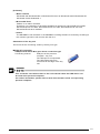
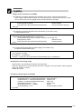
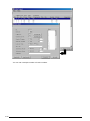
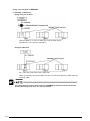
Attachment of the key unit
The format of the connecting varies by the key unit type.
IBM PC/AT compatible
USB(Universal Serial Bus) port direct connection type
Connecting method
: USB port of the personal
computer - key unit
The USB port is monopolized.
The USB cable cannot be
connected to the edge of the key
unit.
This cannot be used unless there is the environment where the USB device can
be used at the personal computer.
For further information, please refer to each of the manuals of the corresponding
personal computer.
1-3
1.2
Version Up from Ver1.** or Ver2.**
Usually, when you installed PCWAY, PCWAY automatically converts to new files from the old files
of PCWAY.
But, executes below when the work folder of PCWAY is 2 or more.
1. There is "W_TCcvt.exe" in the new PCWAY install folder.
Copy "W_TCcvt.exe" to the work folders of the old version.
2. Execute "W_TCcvt.exe" in the work folders of the old version.
1-4
1.3
Installing
1. Verify whether Windows® and Microsoft® Excel has been installed, or not.
If Windows® and Microsoft® Excel has not been installed, please make sure that those are
installed, before you install PCWAY.
2. Start Windows® operating system.
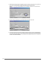
3. Set the PCWAY floppy disk no.1 in to the disk drive, and execute setup.exe.
4. When the program for the installing has started, follow the instructions which has been
displayed on to the screen.
Please make sure that you have filled-out the form which we have included in the
package. This will be the user’s card.
Please send this back to our company after you have filled this out.
1-5
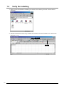
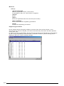
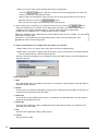
1.4
Verify the Installing
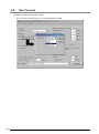
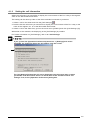
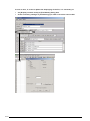
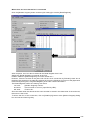
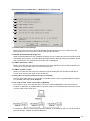
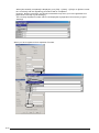
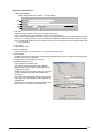
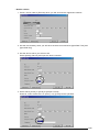
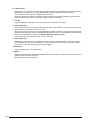
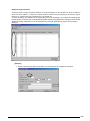
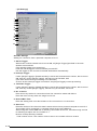
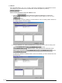
1. When you have finished the installing procedures, the following “Groove” window will be
displayed.
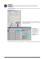
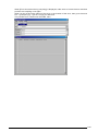
2. Start Microsoft® Excel and verify whether the PCWAY menu and PCWAY icons have been
displayed, or not.
Menu
Icon
1-6
Chapter 2
Overview - PCWAY
2.1
PCWAY Memory Area
Here, we explain about the relay and the register of the PLC.
Also, we explain about the PCWAY event, and the trigger and the “informing” which takes place
with the internal processing.
2.1.1
Explanation on the Relay
With PCWAY, the relay of the PLC is expressed as the "relay".
The acceptance of the usage of the relay and the possible range for the relay numbers for usage,
varies by the PLC type which is adopted for use.
1. X: External Input
X of PLC: External input
Only possible to READ.
2. Y: External Output
Y of PLC: External output
Possible to READ and WRITE.
3. R: Internal Relay
R of PLC: Internal relay and also the special internal relay concerning the internal relay, READ
and Write is possible.
With the special internal relay, it is possible to only READ.
4. T: Timer
T of PLC: Timer Relay
Only possible to READ. (Cannot WRITE)
5. C: Counter
C of PLC: Counter Relay
Only possible to READ. (Cannot WRITE)
6. L: Link Relay
L of PLC: Link relay
Possible to Read and WRITE.
2-2
7. M: Relay Link Area
This is the most important area used for the “trigger”(-introduced later on, in this manual).
Only possible to READ.
• When using the MEWNET-H link board.
When the relay link range has been set with the MEWNET-H Setting Software (independently
sold), the recognition starting from MO will be possible.
• When using the C-NET (RS232C) network type
As the same as the MEWNET-H, with PCWAY it is possible to set the relay link area
simultaneously, by doing the registering at C-NET Settings.
When the network type is MEWNET-H, the registered contents at "C-NET
Settings" will no longer be valid.
• When using the modem network type
As the same as the upper C-NET (RS-232C), when using C-NET Settings to set a similar
relay link area, it is necessary to use the C-NET No. adapted to each of the Modem Support
registering.
8. Other relays
It is not possible to use the P (Pulse Relay) or the E(Error Informing Relay) with PCWAY.
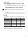
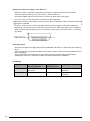
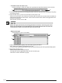
[Summary]
Relay
READ
WRITE
Use as Trigger
X: External Input relay
A
N/A
N/A
Y: External output relay
A
A
N/A
R: Internal relay
A
A
N/A
R: Special internal relay
A
N/A
N/A
T: Timer
*A
N/A
N/A
C: Counter
*A
N/A
N/A
L: link relay
A
A
N/A
M: Relay link area
A
N/A
A
P: Pulse relay
N/A
N/A
N/A
E: Error informing relay
N/A
N/A
N/A
A: Available
N/A: Not available
*If the network type is MEWNET-H, the timer and counter are not able to do “READ”.
2-3
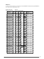
2.1.2
Explanation on the Register
With PCWAY, the memory area of below is expressed as the "Register".
It is possible to change the contents of what will be displayed on to the Microsoft® Excel cell, by
the value and the character code which has been stored inside the register.
Whether it is possible to use a certain memory area and the memory area range which can be
used, varies by the PLC type.
1. DT: Data register
Possible to Read and WRITE.
2. LD: Link register
Possible to Read and WRITE.
3. FL: File register
Possible to Read and WRITE.
4. SV: Setting value of the timer / counter
Possible to Read and WRITE.
5. EV: Elapsed value of the timer / counter
Possible to Read and WRITE.
6. dt: Special data register
Only possible to READ.
7. m :Data link area
This is the memory area which is valid only when the network type is MEWNET-H.
Only possible to READ.
• When using the MEWNET-H link board.
Recognizes starting from m0 according to the range of the data link area which has been set
with the [MEWNET-H Setting Software](independently sold).
• When using the C-NET (RS-232C) network type
This is not possible to use.
• When using the modem network type
This is not possible to use.
8. WR: Internal Relay
Possible to Read and WRITE.
9. WX: External Input
Only possible to READ.
2-4
10.WY: External Output
Possible to Read and WRITE.
11.WL: Link Relay
Possible to Read and WRITE.
12.Other memory areas
The index registers are not possible to use with PCWAY.
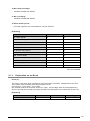
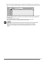
[Summary]
Relay
READ
WRITE
DT: Data register
A
A
LD: Link data register
A
A
FL: File register
A
A
SV: Setting value of timer and counter
A
A
EV: Elapsed value of timer and counter
A
A
dt: Special data register
A
A
m: Data link area
A
N/A
WR: Internal Relay
A
A
WX: External Input
A
N/A
WY: External Output
A
A
WL: Link Relay
A
A
Index register
N/A
N/A
A: Available
N/A: Not available
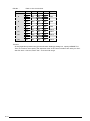
2.1.3
Explanation on the Event
Event (V)
The event is the relay which operates in the internal part of PCWAY, independent to the PLC.
The notation method which exists with PCWAY is from:
Concerning V, V0 to V99F. In all, 1600.
(the notation method is the same as the PLC relay : the first digit under is the hexadecimal.)
This is used with the internal processing and does not take place at the same time as the PLC.
[Summary]
Relay
READ
WRITE
Use as Trigger
V: Event
A
A
A
A: Available
2-5
2.1.4
Explanation on the Trigger and the "informing"
Definition of the Trigger
With PCWAY, it is possible to display the PLC data on to the Microsoft® Excel sheet.
Such visual performances are possible.
Also, it is possible to perform internal matters, such as accumulating data into the file, or the
playing of the sound.
The relay and the event which is used to start such internal tasks are called the "trigger".
Only the relay (relay link area-(M)) and the event (V) can be registered as the "trigger".
When this relay link area (M) or the event (V) has changed from OFF -> ON, each of the
internal processing will be started.
•
The event (V) can be used as the trigger independent to the network type.
•
The Relay link area (M) used as the trigger, varies by the network type.
• When using the MEWNET-H Link board
It is necessary to adapt to the relay link area which has been set using the [MEWNET-H
Setting Software]. (Independently sold)
• When using C-NET (RS-232C) network type
You must make sure to have the area which will be used as the relay link registered at C-NET
Settings.
The relay which can be specified as the link relay is either the R: internal relay or the L: link
relay.
• When using the Modem network type
It is necessary to have the area which will be used as the relay link, registered based on the
networks connected to each of the PLCs.
It is crucial to register this at C-NET Settings.
The relay which can be specified as the link relay is the R: internal relay or the L: link relay.
• When using no network
The relay link area cannot be used as the trigger.
• When using Ethernet network type
You must make sure to have the area which will be used as the relay link registered at [C-NET
Settings].
The relay which can be specified as the relay link is either the R: internal relay or L: Link
relay.
Definition of Informing
The word "informing" has been adopted for use to describe that each of the internal processing
which have started due to the trigger, have completed.
Use this trigger to perform handshakes with the PLC or start each of the internal processing
consecutively.
2-6
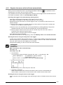
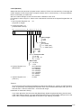
Example of Handshaking Performances with the PLC by the Trigger and the Informing
Relay
(When the trigger is the relay link area: M)
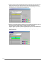
Here, we explain about this, using the network type of C-NET(RS-232C) as an example.
1. Select [Various Types of Records (O)]->[C-NET Settings (N)] and set R0 to RF as the relay link
M0 to MF.
By doing so, with the turning ON of the R0 of the PLC, it is possible to have PCWAY recognize
M0 turning to ON.
It is not possible to have R0 recognized as the trigger at this point.
When connected with C-NET(RS-232C), it is necessary to registering at [C-NET Settings].
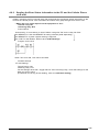
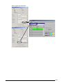
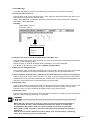
2. If you would like to have the trigger turn to on when the input X0 has turned on, it is necessary
to have a program at the PLC as of the figure below:
The trigger here is R0.
(With PCWAY, by the prior 1procedures, it is possible to have this recognized as M0)
After X0 has turned ON and having R0 turn ON, this will be put to self-hold.
PCWAY will receive that R0 has turned to ON(M0 turning ON) and will start the internal
treatment(file processing ; etc.).
By registering the R100 as the informing relay at each of the registering menus of the various
types of internal treatment, the following will happen:
After the internal treatment has finished, and PCWAY has turned R100 to ON, after a certain
pulse width, (initial value: 500msec) PCWAY will confirm that R0 has turned OFF and then
PCWAY will next turn OFF R100.
When trigger R0 does not turn OFF although the informing relay R100 has turned to ON, due to
a problem of the program at the PLC side, R100 will not turn to OFF.
As described above for the PLC side, it is necessary to have a program which will self-hold
itself adapted to the operations of the informing and the trigger of PCWAY.
When the relay link area: M has been set as the trigger, it is necessary to set the
informing relay.
2-7
Operations when the Trigger is the Event: V
When the event: V has been specified as the trigger, PCWAY will perform the internal
treatment (file processing; etc.) when event: V has turned to on.
And then PCWAY will turn off the event: V which has been set as the trigger.
In such a case, it is not necessary to specify the informing relay.
Specify this when it is necessary for you to inform the PLC that the PCWAY internal treatments
has been completed.
However, for the event: V which has been specified as the trigger at the [Sound Startup]
registering, PCWAY will not turn OFF this event even when the sound playing has completed,.
After you have confirmed the sound, it is necessary for the user to turn OFF event: V, manually.
(by hand)
Informing Event
Apart from the upper informing relay which handshakes with the PLC, there exists the informing
event.
The informing event promotes PCWAY to turn ON the event: V after the internal treatment has
been completed.
This is used when you would like to have other internal treatment started sequentially
independent to the PLC after the PCWAY internal treatment has completed.
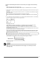
[Summary]
2-8
Trigger
Action after the
internal treatment
Registration of
informing relay
informing event
Relay link (M)
Informing relay turns on
with pulse
Indispensable
Turns on after the internal
treatment
Event (V)
Event (V) turns off
Not indispensable
Turns on after the internal
treatment
2.2
Basic operations of PCWAY
Here we will introduce general performances which are possible with PCWAY.
Also, the range of the possible performances expands when you use the macro of Microsoft®
Excel, or by using each of the small programs together (the initial registering of each program is
required first).
What is possible:
1. Real time display of the PLC memory area at the Microsoft® Excel cell
2. Changing the PLC memory area directly from the Microsoft® Excel cell
3. Saving the PLC data into the file and displaying the data which has been saved into the file.
4. Other useful functions
1. Real time display of the PLC memory area at the Microsoft® Excel cell
With PCWAY, only the currently displayed (active) sheet information can be changed.
The sheet information which has not been displayed will not be updated.
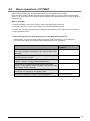
Contents
Function/registration that
is related
The Character and the color which will be displayed on to
the cell is changed by the status of the relay and the event.
(ON/OFF)
Character Change
The register value is computed and is displayed on to the
cell with decimal numbers.
Operation Formula
Displays the register value by binary, hexadecimal, MEW
notation (only the 1st digit under-hexadecimal).
Recognizes the contents which has been continuously
stored in to the register as the character code (ASCII code)
and displays as the character.
Changes the character and color which will be displayed at
the cell (at 101 stages) by the register value.
Message
The current situation of the PLC relay is displayed.
Character Change
2-9
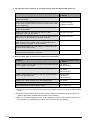
2. The memory area of the PLC is changed directly from the Microsoft® Excel cell
Contents
Function/registration that
is related
By double-clicking the cell, the relay of the PLC is reversed.
(Level Operation)
Character Change
After you double-clicked the cell turning the relay of the PLC
to ON, after a certain period of time, the relay turns to OFF.
(Pulse Operation)
Character Change
Double-click the cell, and turn ON the PLC relay, regardless
of the current status.
Character Change
Double-click the cell, and turn OFF the PLC relay,
regardless of the current status.
Character Change
After you have finished inputting, perform an operation and
then store in to the register by decimal numbers.
Operation Formula
Operation Formula
Store the binary numbers, hexadecimal numbers and the
MEW notation (the 1st digit under is the hexadecimal) of
which you have inputted, in to the register.
The character which you have inputted, is stored in to the
register as the ASCII code.
Downloads all at once, the contents of the cells of which the
range has been specified, to the PLC.
Download Data
3. Save the PLC data in to the file or display the saved data
Contents
Function/registration that
is related
PCWAY saves the PLC data in to the file at optional timings
by the trigger from the PLC.
File Master
File Processing
PCWAY saves the PLC data in to the file at regular intervals.
Interval Timer
File Master
File Processing
PCWAY saves the PLC data in to the file, at the specified
time of the specified date.
Weekly Timer
File Master
File Processing
Displays the saved file data on to Microsoft® Excel.
File Master
Saves as the Microsoft® Excel book.
Save Excel File
Saving Microsoft® Excel books as HTML
Save HTML File
• The saving of the PLC data in to the file performs independent to the running of Microsoft®
Excel.
• The data which has been saved is CSV format. Therefore the displaying of the data at a
different application besides Microsoft® Excel is possible.
• There are 2 optional selections in all, at the displaying of the formerly saved file data on to
Microsoft® Excel. [Update file contents each time] and [Do not update].
2-10
4. Others
Contents
Function/registration that
is related
Turn ON the PLC relay and the event at a certain interval.
Interval Timer
Turn ON the PLC relay and the event at a specified time at a
specified date.
Weekly Timer
Starts automatically the macro which the user has prepared.
Auto Macro Startup
The WAV file is generated at a specified time.
Sound Startup
The event is turned ON by the changing of the PLC relay
(relay link area) .
Event Startup
Connects with distant PLC's through the modem.
Modem Support
Updates all sheet information inside the book.
Update All Sheet Data
Updates all sheet information of a currently active sheet.
Update Active Sheet Data
PCWAY is connected to one PLC through RS-232C (or
Ethernet) and communicates with other PLCs through the
PLC link unit.
Operation Preferences
(Option)
(Use Link unit No.)
By performing the compiling, PCWAY acts with high-speed
performance.
Operation Preferences
(Option)
(Sheet data no-refresh mode)
Transfers the execution environment, such as data
registered for the PCWAY, to another personal computer
Backup Utility
2-11
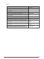
2.3
Basic Specifications
Item
Specification
The number of cells which can set to the PLC relay,
register and the event on to one sheet.
8191 cells
The number of files which can be displayed on to one
sheet.
100 files
Maximum number of cells which can be downloaded
to the PLC at once.
8191 cells
[Character Change] by ON and OFF of the relay and
the event.
100 types
[Operation Formula] for the register
100 types
The registered message which changes by the
register value.
100 types
(4097 stages/types)
[File Master]
600 types
Maximum record number
Maximum field number
Generation
30000 records
256 field/records
3 generations/files
File Processing (File Trigger)
2000 types
Event Startup
1000 types
Weekly Timer
100 types
Interval Timer
100 types
Auto Macro Startup
1000 types
Sound Startup
1000 types
Modem Support
64 types (64 areas)
Modem Connection
4096 regions
Application Startup
100 types
Ethernet Remote
254 types
E-mail Setting
100 types
Maximum number of PLC to connect
254 units
(However, this relies on the maximum
number which can be connected for the
network type)
Layer number of the MEWNET link
Only one layer (After the 2nd
layer-invalid)
For the differences in modem response registration and modem connections,
please refer to section, "Modem (Up To 64 Remote Regions)" and section,
"Modem (Over 65 Remote Regions)".
2-12
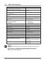
2.4
Module
PCWAY is made up of 3 modules, in all.
Add In Software :
Displays the PLC relay and register values on to the Microsoft® Excel cell, or downloads data
which has been entered in to the cell, to the PLC.
This covers the visual performances, such as the displaying of the data.
It is necessary to have PCWAY.EXE (of below) running, in order to have the PLC relay or the
register value displayed on to the Microsoft® Excel cell.
Module for register :
With PCWAY we have prepared various modules in order to make your usage of PCWAY,
program less as possible.
For further information on this area, please refer to: Module
PCWAY.EXE :
This covers the part which is not visible to the user, such as the processing areas (file
processing; timer processing, for example) or the communication with the PLC.
This part of the package becomes the core of the program.
PCWAY.EXE must always be running.
Even if you do not have Microsoft® Excel running, as long as this module is being runned, the
logging of the data is possible.
2-13
2.5
2.5.1
Precautions
Operation Preferences
• It is not possible to use the MEWNET-H network when you have installed PCWAY with
Windows NT®.
Other network types can use it.
• When using node number 0, it is not possible to use the MEWNET-H, Ethernet(Remote)
network.
Also, when the network type is C-NET or the modem, it is not possible to use node number
0 when you are using the C-NET adapter for the system.
And, if you use ET-LAN unit in Ethernet (local), Pay attention because Unit No.0 can't use.
When using C-NET or the modem, there will not be an error displayed, and PCWAY will
operate irregularly, or an end the program.
• When there is not much memory area of the personal computer, PCWAY might not operate
correctly.
Therefore we recommend the use of the memory area over 32MB.
• PCWAY might not operate correctly when there are a several other programs added-in to
Microsoft® Excel.
Please make sure to remove the Add-In programs.
• Booting Microsoft® Excel more than once and beginning monitoring on two or more
Microsoft® Excel programs is not permitted.
• Please attach the key unit which is included inside the package.
Without this being attached, PCWAY will not operate.
2-14
2.5.2
Operations of PCWAY
• Only the data of a currently active sheet can be updated, for instance the PLC information
which has been set on to the Microsoft® Excel cell, or the file data.
Concerning the sheet which is not currently active, the displaying will not be updated.
When you would like to save the contents of a current book, it is necessary to update all of
the sheets.
For further information, refer to 5.12 Update All Sheet Data.
• When you happen to delete or insert an Microsoft® Excel row, column or a cell, during the
running of the monitor, it is possible that the PLC data and the relay display position might
shift a little.
It is necessary to stop the monitor first, and then perform the deleting or the inserting.
• When each of the registered contents or the matters which have been set before have been
changed, unless you select the Click [Read PCWAY Settings Again]
to operate the changed contents.
, it is not possible
• For the settings below, it is necessary to re-start PCWAY after you have finished this, or else
the changed contents will not be possible to operate.
- Operation Preferences
- Connection No. (for the node numbers)
- File Master
- File Processing
- File Trigger
- Event Startup
- Weekly Timer
- Interval Timer
- C-NET Settings
- Auto Macro Startup
- Sound Startup
- Modem Support
- Application Startup
- Ethernet Remote
- E-mail Setting
2-15
2.5.3
Trigger
With the PCWAY, various types of processing are registered so that they are initiated when a
corresponding trigger goes on.
When working with triggers, the following items should be confirmed.
1. File Processing
When the same trigger has been set for the different [No.]s of [File Processing], the file
processing corresponding to each of the registered number at [No.], will be executed, in turn.
2. Auto Macro Startup
When the same trigger has been set for the different [No.]s of [Auto Macro Startup], the macros
corresponding to each of the registered numbers will be executed, in turn.
3. Sound Startup
When the same trigger has been set for the different [No.]s of [Sound Startup], each of the
sounds corresponding to the registered number will be played in turn. –This will be repeated
over and over.
4. Event Startup
When the same trigger has been set for the different [No.]s at [Event Startup], the registered
event corresponding to each of the registered numbers, will be turned to ON, in turn.
5. Application Startup
When the same trigger has been set at [No.] s of different Application Startup windows®,
applications associated to [No.] is started in turn, starting from the smaller number which is
registered.
6. Ethernet Remote
When the same trigger has been set for the different [No.]s of [Ethernet Remote], the file
processing corresponding to each of the registered number at [No.], will be executed, in turn.
7. E-mail Settings
When the same trigger has been set for the different [No.]s of [E-mail Settings], the file
processing corresponding to each of the registered number at [No.], will be executed, in turn.
2-16
2.5.4
•
Same Trigger Setting
When the same trigger has been set for each of the registering topics, you
must note that in such a case, only one item for processing which has been
registered will be performed.
(for instance, when the same trigger has been set for "File Processing" and
"Auto Macro Startup" registering).
Concerning on which registered item for processing will be valid, this
varies each time.
Please avoid setting the same trigger.
•
Concerning the numbers (at [No.]) which you register.
The registered item will be executed in the number order where the item
associated with the smaller number is executed first.
Clipboard
With PCWAY, it is possible to use the clipboard when displaying the file data on to the Microsoft®
Excel sheet.
Note that when this clipboard is used at a different application during the running of the monitor,
then the displaying performances for the file data could be affected.
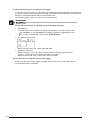
2.5.5
Macro name
The macro name: PCWAY--- is used at the system of PCWAY.
Please avoid using the macro name which starts with: PCWAY--- and including the special
characters when creating the macro program.
You don't add "()" after your Microsoft® Excel Macro Name, when you input your Microsoft® Excel
Macro in Auto Macro Startup.
(Macro Name) Sub TEST() ---> TEST
2.5.6
Special data register
The special data register starts from either the 9000th PLC set or the 90000th set, according to
the PLC type.
Therefore, it is necessary with PCWAY to specify at the "offset" of each of the starting numbers.
PLC type
Special data register
Reserved in PCWAY
FP-e, FP0, FP1, FP-M, FP3, FP-C,
FP5, FP10, FP10, FP10S
DT9000 ~ DT9255
dt0 ~ dt255
FPΣ, FP2, FP2SH, FP10SH
DT90000 ~ DT90255
dt0 ~ dt255
2.5.7
About the file name of Microsoft® Excel
Do not use the special characters for the file name.
PCWAY will not operate correctly, if these are used.
2-17
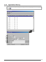
2.5.8
Application Startup
1. Applications cannot be booted by specifying a data file related to an application in the column
for the name of the application to be executed.
For example, "Notepad" cannot be booted by specifying TEST.TXT (a text file) in the
application name column.
To run an application as described above, specify the application name as "Notepad", and then
set TEST.TXT as the argument.
2. Microsoft® Excel should not be booted multiple times to monitor PLC data.
If Microsoft® Excel is booted by booting an external application while monitoring is already
beginning, an error will occur if an attempt is made to begin monitoring again. Monitoring
should only be begun by running one Microsoft® Excel program.
2.5.9
Export function of Each Registering Module
This function added for printing the registering file.
If you edit the exported text file, it can't reflect to the registering file.
Please print the registering file by software that edits the text file.
The software is Microsoft® NotePad and Microsoft® WordPad, Microsoft® WORD, Microsoft®
Excel etc.
The text file is CSV mode.
2.5.10 When you make the macro of the Microsoft® Excel
Verify the performance of your macro on your responsibility before starting up the system.
Matsushita Electric Works, Ltd. will not take responsibility for any abnormal operation due to a
failure in your created macro linked with PCWAY.
Precautions for the users using Microsoft® Excel 97 or later; without fail, describe Macro in the
standard module
• when to call up PCWAY macro function in the macro you created.
• when to register the created macro in the automatic macro start up.
In addition, do not use the macro, SetTimer function of Windows® which is for Windows® directly
to execute. This may cause an abnormal performance in Microsoft® Excel.
2.5.11 Others
1. Limitation item of PLC
FP10S PLC can't use "all nodes" in Cell Settings.
2. PCWAY can't communicate at the same time with other software using the same COM port.
But about Our FPWIN GR of Ver1.1 or more, they can communicate at the same time.
3. You can't together use LINE and TEL in using MODEM.
4. [All nodes] of Node No. in Cell Settings.
It can't use PLC Type.
FP5
FP10
FP3 Less than Ver4.5
FP10S Less than Ver1.5
5. When managing the chart-sheet
When changing the work sheet to the chart-sheet, the monitor of PCWAY will stop.
All PCWAY macros will stop followed by the stopping of the monitor of PCWAY.
Interval Timer, Weekly Timer, and File Processing will not be stopped.
2-18
Chapter 3
Overview - HARDWARE
3.1
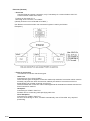
Overview on Hardware
■ PCWAY can be used with all network environments listed below:
-MEWNET-H
-C-NET (RS232C)
-Modem
-Not Connect
-Ethernet (Local)
-Ethernet (Remote)
-USB
It is not possible to use the networks listed above, together.
■ Concerning the PLC(s) which is connected with the computer through RS232C (or the PLC(s)
which are connected to the computer through a modem), it is possible to communicate as node
"0".
■ When the MEWNET-H/ P/ W link unit is attached to the PLC(s) (which is connected by RS232C
as above), then it is possible to access other PLCs situated at the same level, by the following:
Go to [Settings] pull-down menu at [Operation Preferences], and select [Option].
Place a check mark at [Use Link unit No. when connection by RS232C].
•
When PCWAY is connecting to the CPU port of PLC, PCWAY can connect
only Unit No.0
•
When using FP10S, only the tool port can be adopted for use.
■ Concerning the function which enables the informing of PCWAY errors using the modem
([Error Reception] function), it is possible to use these networks (introduced above), together.
However, when PCWAY is connected to the PLC(s) through C-NET (RS232C), you must set
the communication port to another port.
For further details, refer to 3.7 Error Reception.
3-2
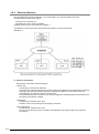
3.2
When Connected by MEWNET-H
■ It is necessary to attach MEWNET-H link board (independently sold) to the computer.
Including the computer which has MEWNET-H Link Board attached to it, the overall number of
connectable nodes are: 64 nodes.
(with 2 computers, the number of the PLC is: up to 62 sets)
However, only PLCs at the same level as the computer only, will be perceived.
In other words, PLCs positioned at different levels will not be perceived.
(In such cases, the MEWNET-H Link Software independently sold will become necessary for
use.)
■ When you would like to start the internal processing of PCWAY, when the PLC turns on the
connections (such as the file processing or the auto macro startup, and the sound playing), it is
necessary to set the relaylink (M) using the MEWNET-H setting software.
For the PLC relay, the internal relay (R) and the relay link (L) can be registered as the "relay
link area".
It is not possible to write into the PLC relay link area from the link board which is attached
to the computer.
For detailed information, refer to the "MEWNET-H Link Unit" manual and other documents.
If using only the functions that display PLC information in Microsoft® Excel cells, or
download Microsoft® Excel cell values to the PLC, it is not necessary to specify a relay
link area (M) in the MEWNET-H settings software.
3-3
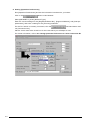
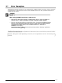
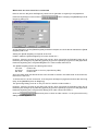
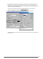
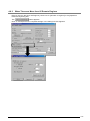
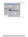
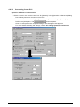
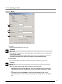
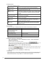
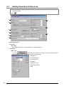
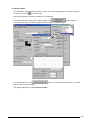
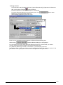
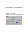
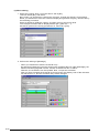
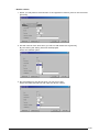
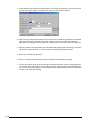
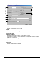
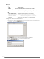
■ Setting [Operation Preferences]
Run [Operation Preferences] and set the information introduced to you below:
Click on the
button under Network.
Select [MEWNET-H] under [Network Type].
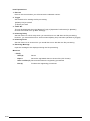
Enter the correct settings for the [Registered Board No.], [Segment Address], and [Interrupt
parameters], and enter a setting for the [Timeout] parameter.
For the PLC which is currently connected, click the
command button and
run [Connection No.].
Place a check mark at the check box for the node which you will adopt for use.
For further information, refer to 6.1 Setting Operation Preferences and 6.16 Connection No.
3-4
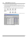
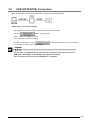
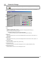
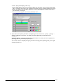
3.3
C-NET(RS232C) Connection
■ The number of the PLC nodes which can be connected to the computer during the C-NET
connection is: Max. 99 nodes (It depends on hardware.)
■ To set up the system so that the internal processing of the PCWAY (functions such as File
Processing, Auto Macro Startup, and Sound Startup) is booted when the PLC turns on the
relay, the [C-NET Settings] of the PCWAY must be used to recognize the various PLC relays
as the relay link area(M).
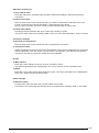
■ By setting [C-NET Settings], the PLC internal relay(R) will be set as the relay link area.
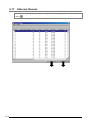
When the PLC type is: FP3, FP-C, FP1OSH, it is possible to set the link area(L), also.
When connected as the figure above, set at [C-NET Settings], as the example introduced to
you below:
For further details, refer to 6.11 C-NET Settings.
3-5
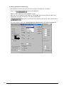
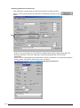
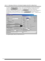
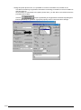
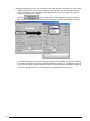
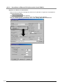
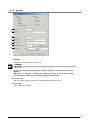
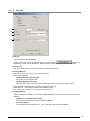
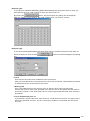
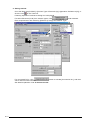
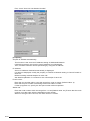
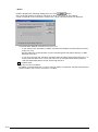
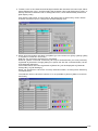
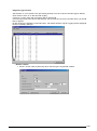
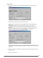
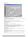
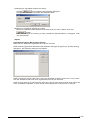
■ Setting [Operation Preferences]
Run [Operation Preferences] and set the information introduced to you below.
Click on the
button under Network.
Select [C-NET (RS232C)] under [Network Type].
Enter the correct settings for the COM Port, Baud Rate, Data Length, Stop Bit, and Parity
parameters, and enter a setting for the Timeout parameter.
and place a check mark at the check boxes for the node numbers which
you will use.
For further details, refer to 6.1 Setting Operation Preferences and 6.16 Connection No..
3-6
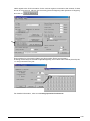
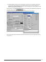
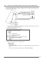
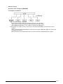
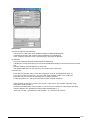
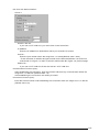
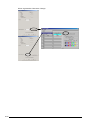
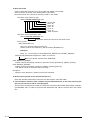
■ When you would like to connect the CPU of the PLC with RS232C and then access to other
PLCs positioned at the same level, set as the following:
At a network such as the one above, when wishing to access PLC No.1~3 (of the figure above),
run [Operation Preferences] and open the [Operation Preferences] dialog box by selecting
[Option] at the [Settings] (of menu bar) pull-down menu.
Place a check mark at [Use Link unit No. when connected by RS232C].
After these settings have been entered, all subsequent access to the PLC is handled via link
code numbers, rather than CPU code numbers.
•
If you did not place a check mark before at the prior dialog box, the No.2
PLC(of the figure above) will be perceived as node number 1.
•
By placing a check mark, only No.2 of above (which is connected directly
with the computer) will be perceived as node number 0 (self node)
regardless of the node number of the link unit.
•
If you attempt accessing to the PLC after placing a check mark, this mode
will not be canceled until the PLC is switched to OFF.
(This can be canceled-however the CPU of the PLC will memorize this.)
In order to cancel this, it is necessary to turn off the switch of the No.2 PLC.
•
When using FP10S, only the tool port can be adopted for your use.
3-7
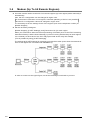
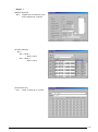
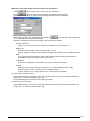
3.4
Modem (Up To 64 Remote Regions)
■ A modem cam be used to monitor PLCs in remote regions (up to 64 regions) either manually or
automatically.
Also, the PLC configuration can be changed in region units.
If connections include 65 or more regions, automatic patrolling of PLCs is not possible,
and the PLC configuration cannot be changed in region units.
It is necessary to set the settings for all of the regions (such as the telephone number) at
[Modem Support].
■ Set the necessary settings at:
[Modem Support], [C-NET Settings], and [Connection No.] for each region.
When you would like to start the internal processing of PCWAY (such as the File Processing,
Auto Macro Startup, and the Sound Startup), by the PLC turning ON the relays of each regions,
it is necessary to have each of the PLC relays perceived as the relay link area(M).
(This is possible by using [C-NET Settings]).
The settings at [C-NET Settings] is necessary only with the modem (even when the networks of
each of the regions are connected with MEWNET-H).
In order to connect as the upper figure, set as the followings introduced to you next.
3-8
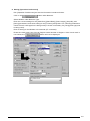
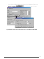
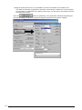
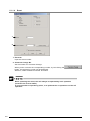
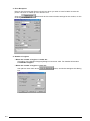
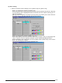
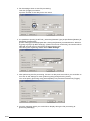
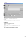
■ Setting [Operation Preferences]
Run [Operation Preferences] and set the information introduced below.
Click on the
button under Network.
Select Modem under Network Type.
Enter the correct settings for the [COM Port], [Baud Rate], [Data Length], [Stop Bit], and
[Parity] parameters, and enter setting for the [Timeout] and [Public Line Timeout] parameters.
Check Pulse if a dial-type line is being used (no check is necessary if a [Tone](push-type) line
is being used).
Enter a setting for the Modem Init command (AT command).
Erase the check mark from Over 65 Regions under Number of Regions. If this check mark is
not erased, the
button will not be displayed.
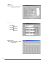
3-9
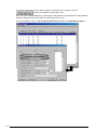
To set the parameters for the various regions connected to the network, click on
, and boot the [Modem Support] function.
Go to the other settings dialog box, entering from the [Details] command button at the [Modem
Support] dialog box and set [C-NET No.] and [Connection No.].
For further details, refer to: 4.8 Using the Public Phone Line and 6.14 Modem Support.
3-10
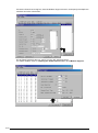
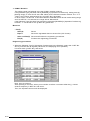
• Region 1
[Modem Support]
No.1:
register the informations such
as the telephone numbers.
[C-NET Settings]
No.1:
No.1 Node 1
WR0-1 word
No.2 Node 2
WR0-1 word
[Connection No.]
No.1:
Place a check at no.1 and 2
3-11
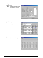
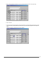
• Region 2
[Modem Support]
No.2:
register the informations such
as the telephone numbers.
[C-NET Settings]
No.2:
No.1 Node 1
WR0-1 word
No.2 Node 2
WR0-1 word
No.3 Node3
WR0-1 word
[Connection No.]
No.2:
3-12
Place a check at No.1, 2 and
3 (at check box)
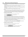
• Region 3
[Modem Support]
No.3:
register the informations such
as the telephone numbers.
[C-NET Settings]
No.3:
No.1 Node 1
WR0-2 word
[Connection No.]
No.3:
Place a check at No.1 (at
check box)
3-13
■ Settings for reception from the PLC
Boot [Operation Preferences], and specify the following information.
Place a check mark by Receive under Network.
Then click on the
button and enter the reception settings.
For detailed information, refer to 6.1 Setting Operation Preferences.
■ When wishing to display the relay link area information onto the Microsoft® Excel cell, specify
[C-NET No.] (the same No. as the Modem Support No.) to that node number.
Within the relay link area, information for different regions can be specified on the same sheet.
When displaying R0 of the PLC node number of region no.3, set 20 from the relay
link area (M) of C-NET No.2.
■ Concerning other PLC information besides of the relay link area, specify the PLC node number
(only for that region).
When displaying Data register (D) 0 of PLC node number 3 of region no.2 (of the
prior figure), set 0 of Data Register (D) of Node 3.
Concerning PLC information besides the relay link area, when you have set
information of different regions onto the same sheet, this will be perceived as
the information of the currently connected region.
It is not possible to set PLC information onto the same sheet besides the Relay
link area.
It is important to make active, the sheet which will display the information of the
connected area, when connecting the lines.
3-14
3.5
Modem (Over 65 Remote Regions)
■ Using a modem, PLCs in remote areas (up to 4,096 regions) can be monitored manually or
automatically.
However, when there are 65 or more regional connections, automatic patrolling of PLCs is not
possible and you cannot change the PLC configurations for each region.
Settings for the various regions (telephone numbers, etc.) must be registered under [Modem
Connection].
For information on using [Modem Connection], please refer to the corresponding Help function.
When [Modem Connection] is booted, a Help item appears on the menu.
■ Specify the [Connection No.] and [C-NET Settings] parameters shared by all of the remote
areas.
To set up the system so that the internal processing of the PCWAY (functions such as file
processing, auto macro startup, and sound startup) is booted when the PLCs in the various
remote regions connected to the network turn on the relays, the [C-NET Settings] of the
PCWAY must be used to recognize the various PLC relays as the relay link area (M).
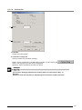
■ Operating environment settings
Boot [Operation Preferences], and specify the following information.
Click on the
button under [Network].
Select [MODEM] under [Network Type].
Enter the correct settings for the [COM Port], [Baud Rate], [Data Length], [Stop Bit], and
[Parity] parameters, and enter setting for the [Timeout] and [Public Line Timeout] parameters.
Check [Pulse] if a dial-type line is being used (no check is necessary if a [Tone] (push-type)
line is being used), and enter a setting for the [Modem Init command (AT command)].
Place a check mark by [Over 65 Regions] under [Number of Regions]. If this check mark is not
entered, the [Over 65 Regions] button will not be displayed.
To set conditions for connections, click on the [Over 65 Regions] button.
For information on the contents of settings, refer to 6.1 Setting Operation Preferences.
Enter settings for the [Over 65 Regions] and [Connection No.] settings.
■ Settings for reception from the PLC
Boot [Operation Preferences], and specify the following information.
Place a check mark by [Receive] under [Network].
Then click on the
button and enter the reception settings.
For detailed information, refer to 6.1 Setting Operation Preferences.
3-15
3.6
Not Connect
■ Select [not Connect] at [Net Type].
This can only handle Event (V), and the gathered file data.
3-16
3.7
Error Reception
Besides the function operation of the modem which enables PCWAY to call up PLCs in remotely
located regions, there exists a function which enables the PLC to call up PCWAY and inform
PCWAY of any errors.
When calling PCWAY from the PLC, make sure to:
•
Set the PLC which will call up as node1 when there is only one PLC in a
remote area, or when connected to C-NET using the C-NET adapter.
•
Place a check mark at [Use Link unit No. when connection by RS232C] when
the PLC of a remote area wants to access to other PLCs of other stations
situated at the same layer (in the condition when it is attached to
MEWNET-H link Unit).
Go to this from the [Operation Preferences] menubar "Setting" pull-down
menu and select [Option].
The [Error Reception] function at [Operation Preferences] can be used with any network PCWAY
is based on, at that moment.
However, during the C-NET (RS232C) connection, it is not possible to use the same serial port
number.
3-17
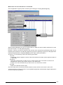
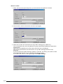
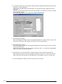
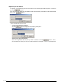
■ Setting [Operation Preferences]
•Run [Operation Preferences] and set the information introduced below.
Place a check mark by [Receive] under [Error Reception], and click on the
button.
- Enter the correct settings for the [COM Port], [Baud Rate], [Data Length], [Stop Bit], and
[Parity] parameters, and enter setting for the [Timeout] and [Public Line Timeout]
parameters.
Check Pulse if a dial-type line is being used (no check is necessary if a Tone (push-type) line
is being used), and enter a setting for the AT command.
For detailed information, refer to 6.1 Setting Operation Preferences.
3-18
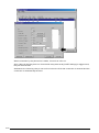
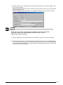
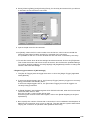
•With regard to the PLC information for the various regions connected to the network, if there
are 65 or more regions, place a check mark by [Over 65 Regions] under [Number of Regions],
and click on
.
Enter settings for [Information Relay] and [Information Event] as necessary.
A setting must always be entered for [Read Register], and a check mark must be placed by No.
1 in the [Connection No.] list.
For detailed information, refer to 6.1 Setting Operation Preferences.
3-19
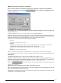
If there are fewer than 65 regions, boot the Modem Support function, and specify the telephone
numbers and other information.
Set at [Read Register] edit box, going from the [All Settings] button.
For further details, refer to 4.8 Using the Public Phone Line or 6.14 Modem Support.
3-20
3.8
Ethernet(Local/Remote) Connection
•
Understand registration of IP address for a personal computer very well, the ET-LAN unit
and Ethernet to use the Ethernet communication.
Prior to using an ET-LAN unit, especially, match a configuration of a personal computer to
configurations of PLCs after understanding descriptions in "ET-LAN instruction manual"
very well.
(PLCs are sure to require a program for specifying IP address.)
•
The number of PLCs connecting with a personal computer via Ethernet counts up to 64.
In use of an ET-LAN unit, however, a personal computer occupying one connection number
decreases the number of PLCs able to connect to maximum 63.
• To start internal procedure of PCWAY (such as the File Processing, the Auto Macro Startup,
and the Sound Startup) by PLCs turning on the relay, each relay of PLCs must be
perceived as the relay link area(M) with [C-NET Settings] of PCWAY.
(The equipment is connected physically via Ethernet, but register with [C-NET Settings])
The Ethernet connection has two types.
3-21
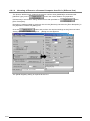
3.8.1
Ethernet (Local)
On Ethernet(Local), PCWAY connects the PC and PLC as soon as executing.
Use the Ethernet local connection ordinarily for full-time communication.
The connection has two types.
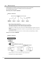
■Not using each link path of MEWNET
• Example of Hardware
*
Max. 64 PLCs can be connected.
Even if using one ET-AN unit, maximum 63 PLCs can connect.
That means a personal computer itself must have a node number.
(See detailed explanation in "ET-LAN Unit Introduction Manual.)
*
Connect PLC to HUB via our ET-LAN unit or the Ethernet/RS232C converter unit on the
market.
When connecting Ethernet/RS232C converter unit, plug the RS232C cable into TOOL port
or COM port of PLCs.
But connection to FP3 require the Ver.4.4 later converter (corresponding to C-NET)
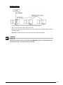
■Using each link path of MEWNET
• Example of Hardware
Using Tool port of CPU
* Check number 0, 2, and 3 to enter the node number above.
* Connect No.1 PLC with the node No.0.
3-22
Using ET-LAN Unit
* Check number1, 2, and 3 to enter the node number above.
* No.1 Link Unit must set the CPU right side.
* When you directly connect PCWAY and our ET-LAN Unit, Ethernet cable uses the
crossing cable.
* MEWNET-H/W/P Link Unit uses nearest at the CPU place please.
Only top hierarchy level in each link unit of MEWNET can be connected while the
second hierarchy level later cannot connected.
3-23
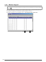
3.8.2
Ethernet (Remote)
Use the Ethernet remote connection, only if necessary for communication with PLC.
Communication starts when either
-Turning on the event(V) or
-Informing error from PLC to PCWAY.
(Usually PLCs are not connected to PCWAY.)
Use Remote connection when user structured system is mainly as follows:
Example 1)
■ Form of connection
The Remote connection has three types.
• Send Line
Connecting to PLCs from PCWAY.
There are two types of Regular Connection method (a method of connection which must be
manually cut) and One Scan Connection method (a method of connection which be
automatically cut off after scanning over PLCs).
The automatically link connection can be also applied to all destinations entered with the
One Scan Connection method.
• Reception
Connecting to PCWAY from PLC.
PCWAY can be connecting until specifying wait time.
• Error Reception
Connecting to PCWAY from PLC.
As soon as receiving an error, PCWAY automatically cuts off line after only required
processing.
3-24
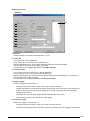
3.9
USB (GT32/GT05) Connection
■One GT32/GT05 unit can be connected to a computer with a USB cable.
■Operating environment settings
Start [Operation Preferences] to specify the following information.
Click the
button of [Net Type].
Select “USB” in the Network Type.
Also, specify the Time-out setting.
For the connected PLC, click
to start [Connection No.], and check the
unit number of the PLC to be connected.
If more than one GT32/GT05 are connected to a computer using devices such as
USB hubs, the PCWAY or GT32/GT05 may operate unusually.
Do not connect more than one GT32/GT05 to a computer.
3-25
3-26
Chapter 4
Basic Operations of PCWAY
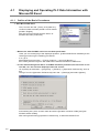
4.1
Displaying and Operating PLC Data Information with
Microsoft® Excel
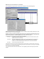
4.1.1
Outline of the Basic Procedures
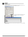
1. Start Microsoft® Excel
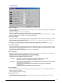
-
First, from the tool bar [Tools], click [Add-ins..].
-
Confirm if there has been placed a check mark at
[PCWAY English]
(the check mark indicates that the add-in of
PCWAY has been performed.)
• What to do when PCWAY add-in has not been performed:
Have you not chosen [No] to the displayed question, [Is Microsoft® Excel installed?] at the
starting point during the installing procedure?
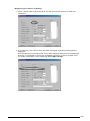
-
If so, go to:
Microsoft® Excel menu bar -> [Tools]->[Add-ins...] and click [Browse...].
then select [PCWAY.xla] from the folder where PCWAY has been installed into.
• In case when although the add-in of PCWAY has been performed, the menu bar or the
tool bar, etc. has not been displayed onto the screen:
-
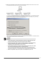
Go to [Start] at windows® -> [Programs] -> [PCWAY] -> [Operation Preferences], and run
this.
Then go from the [Operation Preferences] menu bar -> [Settings] and select [Option].
At this dialog box, place a check mark at both the [PCWAY menubar visible] and [Use
PCWAY toolbar visible].
After saving and finishing [Operation Preferences], re-start Microsoft® Excel.
4-2
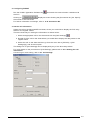
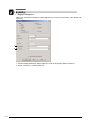
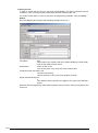
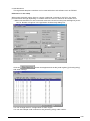
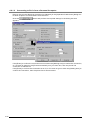
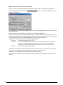
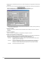
2. Configuring PCWAY
Run the PCWAY [Operation Preferences]
the PLC.
Clicking on
the number to be connected.
and match the communication conditions with
displays a screen showing the [Connection No.] list. Specify
For further information on settings, refer to: 6.16 Connection No.
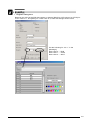
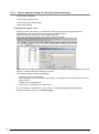
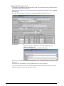
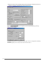
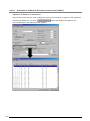
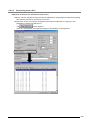
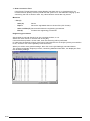
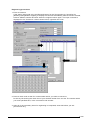
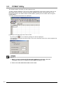
3. Set the cell information
Select the cell on the Microsoft® Excel sheet, where you would like to display the PLC relay
status or the register values.
There are three ways in setting the information as shown below:
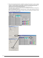
1. Select an appropriate cell on the sheet and click the [Cell Settings]
.
2. Double click the cell on the sheet where you would like to display the relay status or the
register value.
3. Select the cell on the sheet and then go from the menu bar to [PCWAY] ->[Cell
Settings(S)], and click this option.
The dialog box for [Cell Settings] can be displayed by any of the three ways above.
For more details on the procedures of [Cell Settings], please refer to 4.1.2 Setting the cell
information.
Concerning on more setting, refer to 5.1 Cell Settings.
4-3
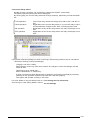
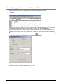
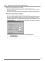
4. Run PCWAY
When the necessary settings for the cell information has been completed, left-click the [Run
PCWAY]
.
•
When
has not appeared onto the task bar under the screen, this
means that PCWAY has not been executed.
Furthermore, if PCWAY has not been executed, the communication with the
PLC will not be possible, later on.
•
If there appears an error sign during the running of PCWAY, left-click the
[Exit PCWAY]
and end the PCWAY program.
and execute the settings,
Next, left-click the [Operation Preferences]
reconfirm the communication conditions with the PLC, and re-do the
settings.
After this, left-click the [Run PCWAY]
once again.
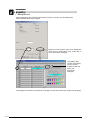
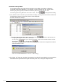
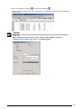
5. Start the monitoring
. The values of the PLC will be displayed on to the cell where
Left-click the [Start monitor]
the information settings have been set.
6. Do the necessary operations below while the monitor is in operation
(These operations can only be done during the running of the monitor.)
Operate the:
-
Changing of the relay status
-
Changing of the register value
-
Operation of the continuous change mode of the register value
-
Data downloading
of the registered cell.
For further information on operation, refer to 4.1.4 How to operate during the running of the
monitoring.
7. Stop the monitor
Click the [Stop Monitor]
.
When you would like to change an operation of the cell settings such as when wishing to correct
something at the information setting, execute the [Stop Monitor]
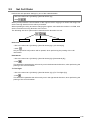
.
Concerning the information settings, this can be set during the starting of the monitor. However,
it is necessary to change this part temporarily to another sheet, so that the displayed settings
can be seen.
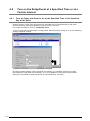
4-4
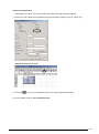
4.1.2
Setting the cell information
Select the cell where you would like to display the current status of the PLC relay or the register
value on the Microsoft® Excel sheet.
The setting can be done by either of the three methods introduced to you below:
1. Select a cell on the sheet and click the [Cell Settings]
.
2. Double click the cell where you would like to display the current status of the PLC relay or the
value of the register, etc. on to the Microsoft® Excel sheet.
3. Select a cell on the sheet first, go from the menu bar to [PCWAY] and click [Cell Settings (S)].
With either of the methods, the displaying of the [Cell Settings] is possible.
For further information on [Cell Settings], refer to 5.1 Cell Settings.
If you go from the [Operation Preferences] menu bar -> [Settings] and select
[OPTION], the following dialog box will appear onto the screen.
The [Cell Settings] dialog box will not be displayed onto the screen later on when
you double click this unless there is a check mark at the "Double-click for cell
settings" first, at the [Operation Preferences] dialog box.
4-5
•
Relay setting
When wishing to display and operate the R0 status of the internal relay, do the same settings
as the figure below.
Specify the text and the color to be displayed when
R0 is on, and when it is off, under "No. 1" in the list
in [Character Change].
This Select No. is
changeable by
clicking the buttons of
the numbers under
“No.”, which is
located on the very
left side of the
Character Change
dialog box.
The registered contents at [Character Change] can also be used at the other [Cell Settings].
4-6
•
Register setting No.1
The value of the DT0 data register is shown divided by 10. To multiply the value by 10 for
operation and write it to the PLC, enter the settings shown below.
Specify X/10 in the Read column and X*10 in the
Write column under No.1 of the Operation
Formula.
To place upper and lower limits on the value used for the operation, enter values in the [MIN]
and [MAX] columns.
4-7
•
Register Setting No. 2
When you would like to display the data register DT0 to DT5 as a Character code, please set
as below.
1
2
1. Set the Display Method to CHR:Character Code at the Display Method edit box.
2. Set to 6 at the No. of Words edit box.
4-8
•
Register setting No.3
Based on the value of the DT0 data register, to display [RUN] for a DT0 value of 0, [STOP] for
a DT0 value of 1, and [WAIT] for a DT0 value of 2, enter the settings shown below.
Set the following for “No. 1” in the
[Message]:
Data value 0 --- RUN
Data value 1 --- STOP
Data value 2 --- WAIT
4-9
•
Setting of Event
When displaying and operating the status of event V0 status, do the settings as
demonstrated below by the figure.
Specify the text and the color to be displayed
when V0 is on, and when it is off, under "No. 1"
in the [Character Change].
The [Select No.]
can be changed by
clicking on the
number at the left
end in the
[Character
Change].
The registered contents at [Character Change] can also be used at the other [Cell Settings].
4-10
4.1.3
Copying and pasting the cell information
1. Select a cell which you would like to copy.
Click [Copy Cell Settings]
.
2. Click the cell range where you would like to paste the copied contents.
When you have selected the cell or cells which you would like to paste, click the [Paste Cell
Settings]
.
At this point, the device number and event number of the pasted cells will increment, one by
one.
R0
R1
R2
R3
R4
R5
R6
Before performing the pasting, by clicking [Set Cell Order]
desired pasting direction will be fixed.
For further details, please refer to 5.5 Set Cell Order.
, the setting of the
4-11
4.1.4
How to operate during the running of the monitoring
• Changing the Register
• Changing the Relay status
• The Continuous-Change-Mode
• Data downloading
Changing the register value
Double click the cell where you would like to change the previously registered value.
The [Register Contents Correction] dialog box will be displayed.
With this, input the value at the “New Value” edit box.
When you click OK, the value of the register will be changed.
There can be a number of reasons why the [Register Contents Correction] dialogbox does not
emerge. Please consult the following to fix this.
• Erroneous settings under [Cell Settings]
-
[Target] is not set to [Register].
Select Register, and if any other items need to be changed, correct the Settings of those
items as well.
-
Attribute is set to Read Only
Select either “Read/Write” or “Write Only”.
For more details on setting new values, refer to: 4.1.2 Setting the cell information.
Concerning Setting, refer to: 5.1 Cell Settings.
4-12
Convert the Relay status
Double click the cell where you would like to change the ON/OFF of the Relay.
The [Relay Operation] dialog box will be displayed.
By clicking [OK], the current relay status will change variously, depending on what has been
set.
Level operation
:
Pulse Operation
:
ON operation
:
OFF operation
:
The current relay status will change from ON to OFF, and OFF to
ON.
Regardless of the current relay status, if you turn the relay to ON, it
will automatically change to OFF after a certain period of time.
Regardless of the current relay status, the relay will always turn to
ON.
Regardless of the current relay status, the relay will always turn to
OFF.
If the [Relay Operation] dialog box does not emerge, the following reasons can be considered:
• Erroneous settings under [Cell Settings]
-
[Target] is not set to “Relay”.
Select [Relay], and if any other items need to be changed, correct the settings of those
items as well.
-
[Attribute] is set to “Read Only”.
Select “Read/Write” or “Write Only”.
-
A check mark has not been placed next to [ON/OFF confirmation message] by selecting
[Settings on the operation Preferences] menu bar, and then [Option].
The system will operate correctly in this case.
For more details on the procedures refer to: 4.1.2 Setting the cell information.
Concerning on more setting details, refer to: 5.1 Cell Settings.
4-13
Continuous Change Mode
If the register value is lined up next to each other in the Row and Column of direction
(horizontal and vertical direction), it is possible to make changes with the register value
without going through the procedures of selecting only up to one cell at a time.
Concerning the moving direction of the cell or cells, set the
at the [Set Cell Order].
1. First, double click the cell which you would like to change, starting from the one that comes first.
The [Register Contents Correction] screen will be displayed.
Choose “Continuous Change”.
position, the [Continuous
• If the movement mode of the cell is in the “No Action”
Change] message window will be displayed.
At this point, it is important not to ignore the setting of the cell movement mode to either
, or “To the right”
.
“Downward”
Click “OK”, set the movement mode of the cell, and then execute once again the matters
instructed above at No.1.
Refer to: 5.5 Set Cell Order on how to do the setting.
2. By clicking “OK” after the changing of the register, the cells will automatically move towards the
selected direction specified at the [Set Cell Order]. With this, change the register value.
4-14
How to download data
Download to the PLC, the values where the range has been specified already.
1. Specify the cell range where [Attribute] of the information setting is set as “Write only”.
Specified range of the cells.
2. Click the
or go from the [PCWAY] in the menu bar to [Download Data].
For more details, refer to 5.11 Download Data.
4-15
4.2
Saving PLC Information into the File
4.2.1
The file
With PCWAY, it is possible to save PLC information into the hard disk.
The gathered data which has been saved into the hard disk, is called a file.
The file we are referring to now is not the Microsoft® Excel book file one.
A file is made up of 2 types of information sources-field and record.
[The constitution of the file]
field No.1
Example
Date
field No.2
field No.3
field No.4
Time
Production No.
Defect No.
Record1
Record2
Record3
Field
A field indicates a data item.
Items such as the date, time, and number of production are called fields.
Settings can be entered for up to 256 fields (items).
There are 5 field types which can be set with PCWAY: Date, Time, Integer, Real Num., and
Char.
Select the type which matches best with the item.
Date
: month / day / year (4digits) (MM/DD/YYYY)
Time
: hour / minute / second (HH:MM:SS)
Integer
: LONG (-2147483648-2147483647 range)
Real Num.
: DOUBLE (1.7E-308-1.7E+308 RANGE)
Char.
: storable up to 32 characters (this is not UNICODE).
Record
A group (one horizontal row in the previous page) of the fields (data items) discussed in the
previous page is called a record.
Data can be saved in units of one record (one horizontal row in the previous page) at a time,
and numerous records can be compiled to form a file.
Up to 30,000 records (cases) can be saved.
File
The accumulation of data made up of fields and records, will make up a file.
File name: it is always necessary to give your file a name.
With PCWAY, it is possible to register 600 types of these files.
Since the file is saved in the text format (CSV format), it is possible to open the file at a
different application, besides Microsoft® Excel.
4-16
File Generation
With PCWAY, it is possible to use 3 generation files (of different extensions) for one file.
For instance, when you have registered a file named "TEST", it is possible to use 3 generation
files with PCWAY, such as:
" TEST.1 ", " TEST.2 ", and " TEST.3 ".
TEST.1: named Generation 1
TEST.2: named Generation 2
TEST.3: named Generation 3
Only the Generation 1 (TEST.1) file is capable of constantly saving the PLC information.
The Generation 2 (TEST.2) and Generation 3 (TEST.3) file are used to backup the Generation
1 (TEST.1) file.
File Processing
The processing for the file is called: file processing
File processing is the processing for the file, such as writing-in of the PLC information, or the
copying of the generation 1 file to the generation 2 file (in order to do the backup).
It is necessary to set the PLC register with every field (item) of the file, when saving PLC
information into the file.
For instance, it is necessary to set DT0 of node number 1 for the number of production field,
and for the defect field, then DT1 of node number 1 should be set.
For such a situation, such a program of the PLC which would store the number of production
into DT0, and number of defects into DT1 becomes necessary.
The field for data and time will be written-in automatically by the clock of the computer
when the file processing has started.
Usually, it is possible to register a number of file processings for one file type. For instance,
usually you would write in PLC information into Generation 1 file.
However, when this becomes full, it is possible to copy the Generation 1 file to the Generation
2 file.
Throughout the entire PCWAY program, the number of file processings which you can register
in all is: 2000 entries.
(It is not possible to download the data which has been saved into the file before, to the PLC.)
Communicating with the [File Processing] trigger.
When the trigger turns to ON, the file processing will be executed.
The trigger of above is the trigger for the Relay (Relay link area: M) or the event (V).
By deciding the exact timing when to turn ON this trigger, it is possible to perform the file
processing, at various timings.
For instance,
• By turning the event to on at a certain interval ( [Interval Timer] ), the file processing will also
be performed at a certain interval.
• By turning the event to on at a specified time and date ([Weekly Timer]), the file processing
will also be performed at a specified time and date.
• When [Number in Production] has reached its goal number, turn the relay link to on with the
PLC.
Create the program and perform the file processing using the relay link as the trigger.
Such performances are possible.
For further information on each of the registering, refer to 6.9 Weekly Timer and 6.10 Interval
Timer.
4-17
File processing using the link relay as the trigger
In order to turn the link relay to on at the PLC, it is necessary to do the programming at the PLC
so that the relay link (which becomes the trigger) will self-hold itself. With this, it is possible for
PCWAY to recognize that the relay link has turned to on.
The informing relay is there for you to cancel the self-hold.
For the file processings of linkrelay: L0 and informing relay: R0
•
Preconditions
It is necessary to have PCWAY recognize the link relay: L0 as the relay link: M0.
For MEWNET-H: use the MEWNET-H setting software (independently sold)
For C-NET or the Modem: refer to 6.11 C-NET Settings.
•
The program for the PLC
With the turning ON of X0, L0 will self-hold itself.
•
Operation of PCWAY
With the turning on of L0, the file processing will be executed. The R0 will be
turned to on after the file processing has been completed.
When L0 has turned to off, confirm this, and turn off R0.
The file processing using the event as the trigger.
When using the event as the trigger, PCWAY will turn this event to OFF after the file
processing has been completed.
4-18
4.2.2
Create a file and execute the processing
Here, we will give an example of processing.
•
Settings of the file
Store the processes of the number of production, number of defects, and defect rate, into the
file, at every 1 hour interval.
At every 1 hour, the number in production and number of defects will be re-sated at 0.
Up to 100 of the most updated files (of 100 hrs.) will be saved.
What to prepare with the PLC.
1. Data that needs to be saved must be stored in a PLC register. A program is necessary,
such as storing the number of production in DT0 of the station no. 1 PLC and the number
of defects in DT1 of station no. 1.
To find out the defects rate, a function is used which allows operations to be carried out
on values of registers using the PCWAY, and the results to be stored in a file.
2. A program must be set up so that the time that the equipment has been operating is
added up with the PLC, and when the one-hour point is reached, a relay (here, L0 is
used) goes on that triggers the PCWAY, so that data is held autonomously.
The relay that discontinues this self-hold of the data is called an information relay (here,
it is R0) with the PCWAY.
When L0 goes on, the PCWAY stores the number of production and other information in
a file, and then the PCWAY turns on R0.
A program is required so that this R0 discontinues the self-hold circuit, and resets the
number of production and number of defects to 0.
After confirming that L0 has gone off, the PCWAY turns R0 off.
Preparations for PCWAY
When connected by C-NET(RS232C), in order to use L0 as trigger M0, the settings at
[C-NET Settings] is necessary.
For further information on the setting procedures, refer to 6.11 C-NET Settings.
4-19
Creating the file
In order to create the file, first you must set at [File Master], the saving numbers (record
numbers), each of the field types (data items) and the writing mode, etc.
For further information on each of the items and registering methods, refer to:6.5 File
Master.
Run [File Master] and register the following settings as file no.1.
File Name
:
test
When planning to create a file at the folder besides the work folder,
input at the folder and file name.
Write Mode
:
Insert at end of file
The record at the very most end is the newest data.
Treatment when file data is full :
Continue processing
Always saves the 100 of the most updated records.
Digits after decimal point :
2
(The defects rate is saved to two digits to the right of the decimal
point.)
After the finishing registering, select [Save] option at the pull-down menu list of [File] of the
menu bar.
4-20
Registering the file processing
The target to be read from the data stored in a file, the processing timing, and other items
are stored using [File Processing].
For further information on each of the items and the registering methods, refer to: 6.6 File
Processing
Run [File Processing] and register the following settings as [Execution No.] 1.
Formula No.
:
1
Register at [No.]1 in [Operation Formula] dialog box as the
following figure below.
The X is equivalent to DT1 (number of defects)
When all of the registering has been completed, go to and select [Save] from [File] in the
menu bar.
You have now completed all of the registerings for the file processing.
If you have PCWAY running, the file processing will be executed at the same timing as
when the program of PLC has turned L0 to ON.
4-21
4.2.3
Displaying the file data onto the Microsoft® Excel sheet
Display the file data which you have created, onto the Microsoft® Excel sheet.
1. Select the corner of the cell where you would like to display the file data which you have
created.
All of the file data will be displayed at the selected cell as the first field of the first record.
If there are 100 record files in 3 fields, a range of cells is displayed starting with the selected
cell and extending three cells to the right and 100 cells in the downward direction.
Even if only one record of data has been stored, all 100 cells in the downward direction are
displayed (99 of those cells will be empty). As long as any data at all exists within that range,
the rest of the range will be displayed, with the cells empty.
.
Set the file data displaying at the [Cell Settings] icon
For further information on the settings, refer to: 5.1 Cell Settings
2. When the settings has been completed, click “OK”.
4-22
3. After running [Run PCWAY]
, run the [Start Monitor]
.
When the file processing has been completed, the data will be displayed as the following
shown below:
When updating the file takes too long, select "Do Not Update" instead of
"Updating File Contents Each Time" in "Update Method".
4-23
In such a case, in order to update the displaying of the file, it is necessary to
4-24
•
set [Display renewal event] at [File Master] dialog box.
•
do the necessary settings at [Cell Settings] in order to turn this event to ON.
4.3
4.3.1
Booting Microsoft® Excel Macros Automatically
What is a macro?
The function which allows Microsoft® Excel to run automatically, is called a macro.
By combining the macro with PCWAY, it is possible to automatically generate reports or to change
the colors of the charts by the PLC information.
However, you must have to know a lot about the Microsoft® Excel macro in order to use this
function.
Please use while referring to the precautions introduced to you later on, only after you have
understood the basics of the macro system.
4.3.2
4.3.2.1
Creating the Macro
Procedures on the making of the macro
1. When something has gone wrong when using the macro which you have made, the PCWAY
Add-In program might not operate properly.
Therefore, it is necessary to remove the PCWAY Add-In program from Microsoft® Excel first,
and then do the testing with the macro, alone.
2. Concerning on how to remove the PCWAY Add-In program...
With Microsoft® Excel 97, go to the main menu bar of Microsoft® Excel-> [Tools]-> [Add-Ins...].
Remove the check mark at PCWAY English at the check box lists of the [Add-In] dialog box.
Run PCWAY
Exit PCWAY
Start Monitor
Stop Monitor
Download Data
Update All Sheet Data
Update Active Sheet Data
Save Excel File
Save HTML File
Ctrl
Ctrl
Ctrl
Ctrl
Ctrl
Ctrl
Ctrl
Ctrl
Ctrl
+
+
+
+
+
+
+
+
+
Shift
Shift
Shift
Shift
Shift
Shift
Shift
E
M
+
+
+
+
+
+
+
B
C
D
E
G
H
I
When [Ctrl + Shift + B], [Ctrl + Shift + D], and [Ctrl + E] are pressed in recording
new macros, the following macros are automatically recorded in "Module",
respectively.
Application.Run "PCWAYsubShellPcwayStart"
Application.Run "PCWAYsubRunStart"
Application.Run "PCWAYsubFileSave"
4-25
3. Execute the macro which you have created, going from Microsoft® Excel [Tools]-> [Macro].
Make sure that you have not made any errors.
When an error has emerged when you have started the macro which was created
in the state of PCWAY add-in being registered, then it is necessary to re-start
Microsoft® Excel.
4.3.2.2
Built -In functions
PCWAY is ready with the following built-in functions.
Use when necessary.
Method for inputting
1. When Sub Procedure:
Call Application.Run("Function name", Argument 1,...)
Example) Download Data
Call Application.Run("PCWAYsubDownLoad")
2. When Function Procedure:
Return value = Application.Run("Function name", Argument 1,...)
Example) Specified saving process of Microsoft® Excel file name(File name : TEST)
Dim Filename as String
Filename = Application.Run("PCWAYfncFileSaveNameType","TEST")
4-26
Menubar Toolbar registration function
• Cell Settings
Sub PCWAYsubSetCell
• Delete Cell Settings
Sub PCWAYsubCellDel
• Copy Cell Settings
Sub PCWAYsubCellCopy
• Paste Cell Settings
Sub PCWAYsubCellPaste
• Set Cell Order: No Action
Sub PCWAYsubCellMoveNo
• Set Cell Order: Down word
Sub PCWAYsubCellMoveDown
• Set Cell Order: To the Right
Sub PCWAYsubCellMoveRight
• Start PCWAY
Sub PCWAYsubShellPcwayStart
• Exit PCWAY
Sub PCWAYsubExecuteStop
• Read PCWAY Settings Again
Sub PCWAYsubExecuteRestart
• Start Monitor
Sub PCWAYsubRunStart
• Stop Monitor
Sub PCWAYsubRunStop
• Download Data
Sub PCWAYsubDownLoad
• Update All Sheet Data(with message) Sub PCWAYsubRefresh
• Update All Sheet Data(without message)
Sub PCWAYsubRefreshNoMessage
• Update Active Sheet Data(with message) Sub PCWAYsubSheetRefresh
• Update Sheet Data(without message)
Sub PCWAYsubSheetRefreshNoMessage(Argument 1 as String)
Argument1: Sheet name that renews information
In the case that argument 1 was omitted or in the case that "" was specified,
the active sheet is renewed.
Example) Renews the information of Sheet no.2.
Call Application.Run("PCWAYsubSheetRefreshNoMessage", "Sheet2")
• Save Microsoft® Excel File (fixed File name : Present file name+YYMMDDHHMMSS)
Sub PCWAYsubFileSave
• Save Microsoft® Excel File (possible to specify file name)
Function PCWAYfncFileSaveNameType_
(Argument 1 as String, Argument 2 as Integer) As String
Argument1: Specified file name (File expansion (xls) is not included)
When you registered only the file name, the HTML file is saved to the same
folder as the Microsoft® Excel book file.
Argument2: 0:Saves the original book.
1:Original book is not saved.
(It is 0 in the case of omission.)
Return value: File name which was saved (Folder name accompaniment)
Example) The name called TEST is attached when saving the present book.
The original book is not saved.
Dim strFilename as String
strFilename=Application.Run("PCWAYfncFileSaveNameType", "TEST" ,1)
4-27
• Save HTML File (fixed File name : Present file name)
Sub PCWAYsubHTMLFileSave
• Save HTML File (possible to specify file name)
Function PCWAYfncHTMLFileSaveNameType_
(Argument 1: As String, Argument 2: As Integer) As String
Argument1: Specified file name (File expansion (htm) is not included)
When you registered only the file name, the HTML file is saved to the same
folder as the Microsoft® Excel book file.
Argument2: 0:Saves the original book.
1:Original book is not saved.
(It is 0 in the case of omission.)
Return value: File name which was saved (Folder name accompaniment)
4-28
• Operation Preferences
Sub PCWAYsubShellEnvironUpdate
• Character Change
Sub PCWAYsubShellDisplayChange
• Message
Sub PCWAYsubShellMessage
• Operation Formula
Sub PCWAYsubShellCalc
• File Master
Sub PCWAYsubShellFileMaster
• File Processing
Sub PCWAYsubShellFileLog
• File Trigger
Sub PCWAYsubShellFileTrigger
• Event Startup
Sub PCWAYsubShellEventTrigger
• Weekly Timer
Sub PCWAYsubShellWeeklyTimer
• Interval Timer
Sub PCWAYsubShellIntervalTimer
• C-NET Settings
Sub PCWAYsubShellCNetEntry
• Auto Macro Startup
Sub PCWAYsubShellEventMacro
• Sound Startup
Sub PCWAYsubShellSound
• Application Startup
Sub PCWAYsubShellRunExec
• Modem Support
Sub PCWAYsubShellModem
• Application Startup
Sub PCWAYsubShellRunExec
• Ethernet Remote
Sub PCWAYsubShellEthernet
• E-mail Setting
Sub PCWAYsubShellEMail
• Help display
Sub PCWAYsubHelpDisp
• Compile
Sub PCWAYsubCompile
Internal treatment function
• Confirm the currently connected node number
Sub PCWAYsubMyAppSetUnitState
• Function for obtaining PCWAY execution folder
Function PCWAYfncExecDirectory as String
Return value:
Execution folder
Example)
Dim strFolder as String
strFolder= Application.Run("PCWAYfncExecDirectory")
• Function for obtaining PCWAY work folder
Function PCWAYfncWorkDirectory as String
Return value:
Work folder
Example)
Dim strFolder as String
strFolder= Application.Run("PCWAYfncWorkDirectory")
• Obtains sheet protection password
Function PCWAYfncGetProtect as String
Return value: Password
Example)
Dim strPassword as String
strPassword= Application.Run("PCWAYfncGetProtect")
Supplement example)
This is the example of the removing of the sheet protection of the sheet (for example
Sheet1).
After the above function is inputted, the following function is inputted.
Worksheets("Sheet1").UnProtect StrPassword
The next is the example of the protecting of the sheet, once again.
After the above function is inputted the following function is inputted.
Worksheets("Sheet1").Protect StrPassword
• Changing the interval timer settings temporally
Function PCWAYfncSetIntervalChange(Argument 1 as Integer, Argument 2 as Integer,
Argument 3 as Integer) as Integer
Argument1:
Interval Timer No.(1 to 100)
Argument2:
Execution flag 0: End
1: Execute
Argument3:
Interval time(every seconds)
Return value:
0 :Normal
-1:Interval timer no. and specified error of folder to be executed
-2:Specified error of execution flag
-3:Specified error of interval time
Example)
Execute the interval timer processing of No. 1 at every 3 second interval.
Dim intRet as Integer
intRet= Application.Run("PCWAYfncSetIntervalChange" ,1,0,3)
4-29
• Processing for obtaining the event number status
Function PCWAYfncEventRead(ByVal Argument 1 as String) As Integer
Argument 1:
Event no.
Example) For V21, the argument is "21".
Return value:
0: OFF
1: ON
Example)
To obtain the status of event V21
Dim intRet as Integer
intRet = Application.Run("PCWAYfncEventRead","21")
'If intRet is 1, the event is on, and if 0, the event is off.
• Processing for setting the event number status
Function PCWAYfncEventWrite(ByVal Argument 1 as String, ByVal Argument 2 as Integer) As
Integer
Argument 1:
Event no.
Example) For V21, the argument is "21".
Argument 2:
1: ON
0: OFF
Return value:
0: Normal
Any other value:
Error
Example)
To turn V21 on
Dim intRet as Integer
intRet = Application.Run("PCWAYfncEventWrite","21",1)
4-30
Usages of the functions for PCWAY
• The following example describes the changing of the sheet, using the press button.
When using: PCWAYsubAutoSheet for the changing of the sheet with the macro, make
sure to inform the Add-in program that the sheet has been changed.
Sub Command 1_Click()
Sheets("Sheet1").Select
Call Application.Run("PCWAYsubAutoSheet")
End Sub
'Sheet Change
'inform the Sheet changing
• The following example describes the downloading of the data, using:
PCWAYsubDownLoad
Execute during the running of the monitor.
If Application.DisplayNoteIndicator = False Then
'Download the data which has been entered in to the B15 cell.
Range("B15").Select
'Select the cell
Call Application.Run("PCWAYsubDownLoad")
'Download Data
End If
• The next example describes the back-upping of the data using:
PCWAYfncFileSaveNameType
Dim strFileName As String
Dim strBuffer As String
strFileName= "TestBackup"
strBuffer = Application.Run("PCWAYfncFileSaveNameType",strFileName)
Precautions concerning usage
With PCWAY, the following procedures are registered.
When the properties of the procedures below are changed, then the PCWAY Add-In program
might not operate correctly.
Please be careful.
Procedure various types of settings
With Application
.OnSheetActivate = "PCWAYsubAutoSheet"
.OnDoubleClick = "PCWAYsubDoubleClick"
.OnData = "PCWAYsubDDEAddinEvents"
.DisplayNoteIndicator = True
.ActiveCell.NoteText = "=MEW("
.ScreenUpdating = True
End With
'Sheet activate
'Double click
'DDE Link
'Memo mark
'Memo
'Screen display renewal
4-31
Event procedure relation function
• Sheet data notice processing
Sub PCWAYsubAutoSheet
• Double click processing
Sub PCWAYsubDoubleClick
• Cell input processing
Sub PCWAYsubCellEntry
• DDE Event arrival of the post processing
Sub PCWAYsubDDEAddinEvents
Attention when you use "PCWAYsubDoubleClick" of Event procedure relation
function into Microsoft® Excel Macro.
Use "PCWAYsubDoubleClickEntry", when you want to use
"PCWAYsubDoubleClick".
Ex.)
4-32
Operating ON/OFF the relay of Microsoft® Excel Cell "B2".
Range("B2").Select
Call Application.Run("PCWAYsubDoubleClickEntry");
4.3.3
Register the macro which will start automatically
When you have created the macro, by setting [Auto Macro Startup]
, it is possible to start
automatically, the macro which you have created.
It is possible to set the relay link area(M) and the event(V) as the trigger which will start the macro.
For further information, refer to: 6.12 Auto Macro Startup
Informing the trigger of the automatically starting macro
[Auto Macro Startup] will be started by the trigger turning to ON.
This trigger is equivalent to the relay (relay link: M), or the event(V).
By determining the time when to turn the trigger to ON, it is possible to start the macro at
various timings.
• Start the macro starting at a certain interval by setting [Interval Timer] which enables the
event to turn to ON at a certain interval.
• Start the macro at a specified time of the specified date by setting [Weekly Timer] which
enables the event to turn to ON at a specified time of the specified date.
• Create a program with the PLC which will turn ON the relay link when the number of
production has reached it's goal number.
Start the macro using this relay link as the trigger.
Such performances are possible.
For further information on the registering, refer to 6.9 Weekly Timer and 6.10 Interval Timer.
Starting the macro using the relay link as the trigger.
In order to turn ON the relay link with the PLC, in order to have PCWAY recognize the turning
ON of the relay link, it is necessary to create a program at the PLC side, which will have this
relay link (which becomes the trigger) put to self-hold.
Use [Informing Relay] in order to cancel the self-hold state.
When starting the macro automatically...
link relay: L0
informing relay : R0
•
Preconditions
It is necessary to have PCWAY recognize link relay : L0 as relay link : M0.
When MEWNET-H:
Use MEWNET-H setting software
(independently sold)
When C-NET, or the Modem, refer to 6.11 C-NET Settings
•
Program at the PLC side
By X0 turning to ON, L0 will be put to self-hold.
•
Operation of PCWAY
When L0 has turned to ON, PCWAY will start the macro and turn ON R0 after this.
After PCWAY confirms that L0 has turned to OFF, PCWAY will turn R0 to OFF.
Starting the macro using the event as the trigger
When using the event as the trigger, after executing the macro, PCWAY will turn this event to
OFF.
4-33
4.4
Turn on the Relay/Event at a Specified Time or at a
Certain Interval
4.4.1
Turn the Relay and Event to On at the Specified Time of the Specified
Day of the Week
PCWAY will turn on the relay and event at a specified time of a specified day of the week.
Set the necessary settings at [Weekly Timer] in order to use this.
For further information, refer to: 6.9 Weekly Timer
To turn on relay R0 of node number 1 using pulses, Monday through Friday at 17:30, the following
settings would be entered.
By using together [Weekly Timer] and [File Processing], it is possible to perform the [File
Processing] at a specified time everyday, or by using [Weekly Timer] with the [Auto Macro
Startup], it is possible to generate reports at a specified time, everyday.
4-34
4.4.2
Turn the Relay and Event to On at a Certain Interval
PCWAY will turn the relay/event to on at a certain interval.
In order to make use of this function, set the necessary settings at [Interval Timer].
For further information, refer to 6.10 Interval Timer
When you would like to turn event V0 to ON at a 1 min. interval, set as the figures shown below:
By using together [Interval Timer] and the [File Processing], it is possible to perform the file
processing at a certain interval.
By using together [Interval Timer] with the [Auto Macro startup], it is possible to start the macro at
a certain interval.
Starting time of a certain interval is 0:00 a.m..
For example, If it's "1min" of up settings,
V0 is ON at 0:00, 0:01, 0:02, 0:03........23:59.
For example, If up settings is "1Hour",
V0 is ON at 0:00, 1:00, 2:00, 3:00........23:00.
4-35
4.5
4.5.1
Playing the Sound
Procedures of the sound playing
The playing of the sound file will be started by the trigger turning to ON.
This trigger is equivalent to the relay (link relay :M) or the event(V).
By determining the timing of when to turn ON the trigger, it is possible to perform the sound
playing at various timings.
For example:
• Perform the sound playing at a certain interval by setting [Interval Timer] which enables the
turning ON of the event at a certain interval.
• Perform the sound playing at the specified time of the specified day of the week by setting
[Weekly Timer] which enables the turning on of the event at a specified time of a specified
day of the week.
• Create a program which will turn on the relay link with the PLC when the production number
has reached it's target number and will perform the sound playing using the link relay as the
trigger.
By doing so, it is possible to perform the sound playing using this link relay as the trigger.
For further information on the registering, refer to 6.9 Weekly Timer and 6.10 Interval Timer.
The sound will be played over and over while this trigger is still ON.
Apart from other internal processings, it is not possible with PCWAY, to turn off the event or to turn
on the informing relay with PCWAY.
Please turn off the trigger manually, after confirming the sound.
Playing the sound using the link relay as the trigger
Using the PLC, create a program that enables self-holding of the link relay that will serve as
the trigger.
The playing of the sound can be stopped by assigning a cell in the Microsoft® Excel sheet that
handles pulsed operation of the relay that cuts off the self-holding of the trigger.
Playing the sound using the event as the trigger
When using the event as the trigger, by assigning the cell which will operate this event at the
Microsoft® Excel sheet, it is possible to stop the playing of the sound.
4.5.2
Create the WAV file
PCWAY does not have the WAV file attached to it.
Create the WAV file, etc. in order to play the sound. Use windows® [Sound Recorder]; etc..
4.5.3
Register at Sound Startup
Start [Sound Startup]
possible.
and register the trigger, etc. in order to make the sound playing
For further information, refer to: 6.13 Sound Startup
4-36
4.6
4.6.1
Turn On the Event by the Changing of the Relay
Information of the PLC
Watch the changing of the relay
With PCWAY, it is possible to change the character and the color which you will display later on to
the Microsoft® Excel cell by the PLC relay turning to ON /OFF.
However the use of this is limited to the displaying only.
When you would like to use together the changing of the relay (ON/OFF) with other processing, it
is necessary to follow the matters below.
1. You will need a macro for watching the contents of the currently displayed cell.
2. In order to start this macro with a certain interval, you must register at [Interval Timer] so that
the event will turn ON at a certain interval.
3. The registering for [Auto Macro Startup] which uses this event is necessary.
Since there are many registering required and various types of processing used together after the
registering, the processes on the whole, will be rather slow.
In order to make the usage must easier, follow the next procedures.
Turn the event to ON after watching the changing of the relay to on -> off or off -> on.
Use [Event Startup] which enables to use this event to have other processing used together.
Monitoring is carried out an on ongoing basis no matter which spreadsheet is active, such as the
relay being changes from on to off, or from off to on, and various events can be turned on
individually.
It is also possible to turn the event ON only with one certain sheet that is active.
4.6.2
Have PCWAY recognize the relay which will be watched as the link relay
In order to have the relay constantly watched, it is necessary to have PCWAY recognize this relay
as the link relay area.
The method for this varies by the network type.
When MEWNET-H
It is possible to have the internal relay(R) or the link relay(L) recognized as the relay link
area(M), using the MEWNET-H setting software(independently sold)
For further information, refer to the “MEWNET-H link unit” manual.
When C-NET (RS-232C)
By setting PCWAY [C-NET Settings], it is possible to have the internal relay(R) or the link
relay(L) recognized as the relay link area(M) at every PLC node number.
For further information, refer to: 6.11 C-NET Settings
When using [Modem]
By setting PCWAY [C-NET Settings], it is possible to have the internal relay(R) or the link
relay(L) as the relay link area(M) at every PLC node number.
For further information, refer to: 4.8 Using the Public Phone Line and 6.11 C-NET Settings
4-37
4.6.3
Perform the event startup
It is possible to watch the OFF->ON or ON->OFF changing of the link relay area, and turn ON
each of the different events.
For further information, refer to: 6.8 Event Startup
When you would like to watch the OFF->ON changing of link relay M0 and turn event V0 to ON, set
as the following figures:
By using [Event Startup] with [Auto Macro Startup], it is possible to change the chart color, etc.
4-38
4.7
4.7.1
Managing the File
Manage the file with the generation of the accumulating file
It is possible to save the PLC information into the file whenever the trigger turns to ON, using [File
Processing] of PCWAY.
It is also possible to back-up the accumulated file of the PLC information.
For further information, refer to: 4.2 Saving PLC Information into the File
• As quoted before, PCWAY will handle up to 3 generation files for one file.
Only the generation 1 file (extension .1) can be accumulated in to the file of the PLC
information. It is possible to either copy or transfer this file to the generation 2 file
(extension .2) or the generation 3 file (extension .3), as well.
In order to make this possible, set the necessary settings at [File Processing].
For further information, refer to: 6.6 File Processing
By accumulating every day, data in to the generation 1 file for a month, and then
transferring generation 1 file to the generation 2 file at the end of the month, by doing so,
generation 1 file will be initialized, and generation 2 file will be usable as the prior month's
data file.
Therefore, it would be possible to store the current month's data in to generation1 file, and
the prior month's data in to generation 2 file.
For the generation, only up to the 3rd generation can be used.
When you are in need of a file revision other than this, (file revision besides the
1st, 2nd, and 3rd generation) refer to: 4.7.2 Controlling Files Using the
Microsoft® Excel Book Log.
4-39
4.7.2
Controlling Files Using the Microsoft® Excel Book Log
The inconveniences when saving the Microsoft® Excel book by: "File" -> "Save".
Although it is possible to save the Microsoft® Excel book from the “File” menu, potentially,
there will arise problems with this, such as described below:
1. PCWAY will only update the displaying of the sheet information of a currently active sheet.
Therefore, if a sheet is not active right before it's saving, the data will not be updated from
what has been last displayed (unless you have used only one sheet during the process).
2. When you re-open a formerly saved book and then start the monitor, the data which has
been saved before will be updated, due to the current PLC information and etc.
This is because the PLC information and the cell are held still linked by the [Cell Settings].
What to be careful of when saving the Microsoft® Excel book
As a solution for the prior matters, it is necessary to follow the procedures introduced to you
below, before you save a particular book.
1. When there happens to exist a several number of sheets in a book, it is necessary to do
the settings at [Update All Sheet Data] before saving the book.
of [Update All Sheet Data] or go to the menu bar -> [PCWAY] ->
Either click the
[Update All Sheet Data]
2. Before saving the book, when you would like to erase all of the settings (formerly set) at
[Cell Settings] and save only the data, use [Save Excel File].
Either click the
of [Save Excel File] or go to the menu bar -> PCWAY -> [Save Excel
File].
With PCWAY, the file name which has been saved using [Save Excel File] will be:
the file name before being saved+YYYYMMDDHHMMSS (year, month, day, hour, minute,
second)
By using [Update All Sheet Data] and [Save Excel File] together with the macro, it is
possible to save the file automatically.
4-40
4.7.3
Saving Microsoft® Excel books as HTML
• Active books can be saved as HTML by selecting one from the following three options:
1) [HTML File Save] icon on the PCWAY tool bar
2) PCWAY menu
3) Shortcut key “Ctrl + M”
Microsoft® Excel books can also be saved as HTML by calling from the user-created macro in
[Auto Macro Startup].
Built-in macros:
File name automatically saving process: Sub PCWAYsubHTMLFileSave
File name designation saving process: Function PCWAYfncHTMLFileSaveNameType_
(Argument 1: As String, Argument 2: As Integer) As String
Argument 1:
File name to be saved (An extension is not included.)
Argument 2:
0: Original book is saved.
1: Original book is not saved.
(When “Argument 1” is set but “Argument 2” is not set,
the case “0” above is applied.)
Return value: Saved HTML file name (with full path)
What to be careful of when saving the HTML format
1. When there happens to exist a several number of sheets in a book, it is necessary to do the
settings at [Update All Sheet Data] before saving the book.
Either click the
Sheet Data]
of [Update All Sheet Data] or go to the menu bar -> [PCWAY] -> [Update All
2. For a file name saved in “File name automatically saving process” above, the extension “.htm”
is added to the target book name, and the file is created in the same folder as the target file. At
this time, the target book is also overwritten.
To specify file names and folders, use “File name designation saving process” above.
When files and folders have already been saved as HTML automatically, they are overwritten
to save.
When a book is newly created, “.xls” and “.htm” files are saved in PCWAY work folder.
4-41
4.8
Using the Public Phone Line
4.8.1
The Difference between Less than 65 and 65 or More Remote Locations
Public telephone lines can be used to monitor information at remote PLCs (in up to 4,096 regions),
and to display and operate data, and save data to files.
Once a remote PLC is connected to the public phone lines, you are able to use all the functions
provided with PCWAY.
The functions that can be executed may differ depending on how many PLCs are connected.
When there are less than 64 remote regions
1. Even if the network configuration for the remote PLCs is different for different regions, you are
still able to observe all PLCs.
2. When connecting from PCWAY to the remote PLC:
There are two types of connections: ongoing connection (where connection is maintained until
it is severed) and single connection (where connection is automatically severed after all the
remote PLCs are scanned once). Also, you can have the single connection performed all
registered remote regions in rotation.
3. When connecting from the remote PLC to PCWAY:
There are two types of connections as below.
-
Normal reception
Using the same COM port used for 2 above, you can receive data from the PLC.
Once received, you can also have connection maintained until specified.
-
Error reception
Using the same COM port used in 2 above or another COM port, you can receive data from
the PLC.
Once received, the required processed are performed and the connection is automatically
severed.
4. Display functions
Data from the remote region can be displayed on sheets using the Microsoft® Excel
application.
5. Miscellaneous
The registered telephone numbers cannot be used with other tool software such as FPWIN.
If there are remote locations in more than 65 but fewer than 4,096 regions
1. For the network configuration for the remote PLCs, a PLC with a node number of 1 is required.
(The informing relay used to inform the PLC of the connection with PCWAY is limited to node
number 1 and is turned on.)
2. When connecting from PCWAY to the remote PLC:
Only manual connection is possible. You cannot have the single connection performed for all
registered remote regions in rotation as you can with less than 64 remote regions.
3. When connecting from the remote PLC to PCWAY:
There are two types of connections as below.
-
Normal reception
Using the same COM port used for 2 above, you can receive data from the PLC.
Once received, you can also have connection maintained until specified.
-
Error reception
Using the same COM port used in 2 above or another COM port, you can receive data from
the PLC.
Once received, the required processed are performed and the connection is automatically
severed.
4. Display functions
Data from the remote region cannot be displayed on sheets using the Microsoft® Excel
application.
4-42
5. Miscellaneous
The registered telephone numbers can be used with other tool software such as FPWIN.
Differences in the setup
When using the public phone lines to connect a personal computer to the PLCs, the setup
procedures will change depending on whether there are more or less than 65 remote PLCs.
• When less than 65 PLCs are connected, remove the check from the [Over 65 Regions] check
box for Number of regions in the [Operation Preference]s dialog box.
Click the
and other settings.
button that appears and set the [read register], [informing relay],
You can change the PLC configuration for each region.
You can set multiple node numbers for the [informing relay] node number.
4-43
• When 65 or more PLCs are connected, place a check in the [Over 65 Regions] check box for
[Number of regions] in the [Operation Preferences] dialog box.
Click the
Relay], and other settings.
button that appears and set the [Read Register], [Informing
You cannot change the PLC configuration for each region. The PLC configuration is shared by
all regions.
The Informing Relay is on for only the PLC with the node number 1.
4-44
4.8.1.1
Connecting to PLCs from a Personal Computer
When there are less than 65 PLCs connected
The PLC configuration can be set for each region using [Modem Support].
When the events set in [Modem Support] turn on, ongoing connection, rotating connection,
and the like are possible.
You can also set the informing relay for informing the PLCs when connections are made.
More than one node number can be set. It is also possible for informing to the informing event.
When there are 65 or more PLCs connected
The PLC configuration is shared by all regions.
To connect, start up [Modem Connection] and connect manually.
For more information regarding settings, refer to the Help supplied with [Modem Connection].
The Help is viewed by starting up [Modem Connection] and choosing Help from the menu.
To perform the setup for 65 or more connections, place a check in the [Over 65 Regions] check
box for Number of regions in the [Operation Preferences] dialog box and click the
button. Then perform the required settings in the dialog box that appears.
Set the [Informing Relay] for informing the PLCs when connections are made.
The [Informing Relay] is set to on only for the PLC with the node number 1.
button and place a check at node number 1 in the dialog box that
Click the
appears.
It is also possible for informing to the informing event.
4-45
4.8.1.2
Connecting to PLCs from a Personal Computer
Place a check in the [Receive] check box for [Network] in the [Operation Preferences] dialog box
to allow reception of transmissions from the PLCs.
Click the
button and perform the required settings in the dialog box that
appears.
If the [Event] to confirm the connection turns on within the [Waiting time] to confirm the connection,
or if a check is placed in the [Event automatically turn] on check box, then the phone line
connection is maintained.
If the [Event] to confirm the connection turns off, or if it does not go on within the [Waiting time] to
confirm the connection, then the phone line is disconnected.
4-46
When there are less than 65 PLCs connected
Click the [Modem Support] button and then [All Settings] to set the [Read Register].
After reception, the PLC data is read with the Read Register that is set.
Setting the [Read Register] is required at the PLC.
PCWAY reads the [Read Register] PLC node number as 1.
However, if there is a check in the [Use Link unit No. when connection by RS232C] check box in
the dialog box brought up by selecting [Option (O)] from the [Settings (C)] menu of the [Operation
Preferences] dialog box, the [Read Register] PLC node number becomes 0.
The Read Register stores the values given below.
1st word:
2nd word:
3rd word:
[Modem Support] number.
Event number to turn on (specified by HEX).
Fixed to K1.
Since the data value that becomes the event number is stored in the data value of the 2nd word,
that event is set to ON.
To inform the PLC of the connection, click on [Details (D)] button at the [Modem Support] dialog
box and set the informing relay.
4-47
You can set a multiple number of node numbers.
4-48
When there are 65 or more PLCs connected
Place a check in the [Over 65 Regions] check box for [Number of regions] in the [Operation
Preferences] dialog box and click the
button to display the [MODEM (Over 65
Regions)] dialog box.
At this dialog box, set the [Read Register] and after reception, the PLC data is read with the [Read
Register] that is set.
Setting the [Read Register] is required at the PLC.
PCWAY reads the [Read Register] PLC node number as 1.
However, if there is a check in the [Use Link unit No. when connection by RS232C] check box in
the dialog box brought up by selecting [Option (O)] from the [Settings (C)] menu of the [Operation
Preferences] dialog box, the [Read Register PLC node number becomes 0.
The [Read Register] stores the values given below.
1st word:
2nd word:
3rd word:
Fixed to K1.
Event number to turn on (specified by HEX).
Fixed to K1.
Since the data value that becomes the event number is stored in the data value of the 2nd word,
that event is set to on.
To inform the PLC of the connection, click the [Over 65 Regions (O)] button and set the informing
relay at the [MODEM (Over 65 Regions)].
The [Informing Relay] is set to on only for the PLC with the node number 1.
However, if there is a check in the [Use Link unit No. when connection by RS232C] check box in
the dialog box brought up by selecting [Option (O)] from the [Settings (C)] menu of the [Operation
Preferences] dialog box, the [Informing Relay] PLC node number becomes 0.
Click the
button and place a check at node number 1 in the [Connection No.]
dialog box that appears.
4-49
4.8.1.3
Informing of Errors to a Personal Computer from PLCs (Same Port)
The phrase "same port" refers to the port number when [MODEM] is selected under [Network
Type] on the
menu item under Network for [Operation Preferences] in the
under [Error Reception].
PCWAY being the same as that specified for
Reception is made possible by placing a check in the [Receive] check box for [Error Reception] in
the [Operation Preferences] dialog box. Click the
button and perform the
required settings at the [Communication Setting-Operation Preferences [Error... ] dialog box that
appears.
The [Read Register] setting is required at the PLC.
4-50
When there are less than 65 PLCs connected.
Click the [Modem Support] button and then [All Settings] to set the [Read Register].
With this [Read Register], the first 3 words of the PLC data are read. PCWAY reads the PLC with
the node number 1 for the [Read Register].
However, if there is a check in the [Use Link unit No. when connection by RS232C] check box in
the dialog box brought up by selecting [Option (O)] from the [Settings (C)] menu of the [Operation
Preferences] dialog box, the [Read Register] PLC node number becomes 0.
At the PLC, it is necessary to store the values given below.
1st word:
The Modem Support register number is stored as a decimal number (if the register number is
5, store K5).
2nd word:
The event number that you want to turn on during phone line connection is stored as a
hexadecimal number (if the event number is 2F, store H2F)
If there is no event number that you want to turn on, then store H FFFF.
3rd word:
Fixed to the decimal value 0 (K0).
Since the data value of the 2nd word becomes the event number, that event is set to ON.
To inform the PLC of the connection, click on [Details (D)] button at the Modem Support dialog box
and set the [Informing Relay].
4-51
When connection by the phone line is made, it turns from off to on.
Also, if there is link relay that is on from the link relay area set at [C-NET Settings] or trigger event,
they will be executed.
Afterwards, the informing relay is set to off to inform the PLC that connection is severed and the
connection is automatically severed.
4-52
When there are 65 or more PLCs connected
Place a check in the [Over 65 Regions] check box for [Number of regions] in the [Operation
Preferences] dialog box and click the
button to display the [MODEM (Over 65
Regions)] dialog box.
At this dialog box, set the [Read Register], and with this [Read Register], the first 3 words of the
PLC data are read.
PCWAY reads the PLC with the node number 1 for the [Read Register].
However, if there is a check in the [Use Link unit No. when connection by RS232C] check box in
the dialog box brought up by selecting [Option (O)] from the [Settings (C)] menu of the [Operation
Preferences] dialog box, the [Read Register] PLC node number becomes 0.
At the PLC, it is necessary to store the values given below.
1st word:
Fixed to the decimal value 1 (K1).
2nd word:
The event number that you want to turn on during phone line connection is stored as a
hexadecimal number (if the event number is 2F, store H2F)
If there is no event number that you want to turn on, then store H FFFF.
3rd word:
Fixed to the decimal value 0 (K0).
Since the data value of the 2nd word becomes the event number, that event is set to ON.
If it is necessary to inform the PLC of the connection, set the informing relay at the [MODEM (Over
65 Regions)].
The [Informing Relay] turns on for the PLC with the node number 1 only.
However, if there is a check in the [Use Link unit No. when connection by RS232C] check box in
the dialog box brought up by selecting [Option (O)] from the [Settings (C)] menu of the [Operation
Preferences] dialog box, the [Informing Relay] PLC node number becomes 0.
Click the
button and place a check at node number 1 in the [Connection No.]
dialog box that appears.
When connection by the phone line is made, it turns from off to on.
Also, if there are relay links that are turned on and set as trigger events from the relay link area set
at [C-NET Settings], they will be executed.
Afterwards, the informing relay is set to off to inform the PLC that connection is severed and the
connection is automatically severed.
4-53
4.8.1.4
Informing of Errors to a Personal Computer from PLCs (Different Port)
The phrase "different port" means that the port number when [MODEM] is selected under
[Network Type] on the
menu item under Network for [Operation
Preferences] in the PCWAY being different from that specified for
under
[Error Reception].
Reception is made possible by placing a check in the [Receive] check box for [Error Reception] in
the [Operation Preferences] dialog box.
Click the
button and perform the required settings at the [Communication
Setting-Operation Preferences [Error... ] dialog box that appears.
The [Read Register] setting is required at the PLC.
4-54
When there are less than 65 PLCs connected.
Click the [Modem Support] button and then [All Settings] to set the [Read Register].
With this [Read Register], the first 3 words of the PLC data are read. PCWAY reads the PLC with
the node number 1 for the Read Register.
However, if there is a check in the [Use Link unit No. when connection by RS232C] check box in
the dialog box brought up by selecting [Option (O)] from the [Settings (C)] menu of the [Operation
Preferences] dialog box, the [Read Register] PLC node number becomes 0.
At the PLC, it is necessary to store the values given below.
1st word:
The [Modem Support] register number is stored as a decimal number (if the
register number is 5, store K5).
2nd word:
The event number that you want to turn on during phone line connection is
stored as a hexadecimal number (if the event number is 2F, store H2F)
If there is no event number that you want to turn on, then store H FFFF.
3rd word:
Fixed to the decimal value 0 (K0).
The data value stored in the 2nd word becomes the event number, and that event is set to ON.
Furthermore, only the files that are triggered by that event are executed. Once they are completed,
the connection is severed immediately.
You cannot inform the PLC of the connection. The registering of the informing relay becomes
invalid.
4-55
When there are 65 or more PLCs connected
Place a check in the [Over 65 Regions] check box for [Number of regions] in the [Operation
Preferences] dialog box and click the
button to display the MODEM (Over 65
Regions) dialog box.
At this dialog box, set the [Read Register], and with this [Read Register], the first 3 words of the
PLC data are read.
PCWAY reads the PLC with the node number 1 for the [Read Register].
However, if there is a check in the [Use Link unit No. when connection by RS232C] check box in
the dialog box brought up by selecting [Option (O)] from the [Settings (C)] menu of the [Operation
Preferences] dialog box, the [Read Register] PLC node number becomes 0.
At the PLC, it is necessary to store the values given below.
1st word:
Fixed to the decimal value 1 (K1).
2nd word:
The event number that you want to turn on during phone line connection is
stored as a hexadecimal number (if the event number is 2F, store H2F)
If there is no event number that you want to turn on, then store H FFFF.
3rd word:
Fixed to the decimal value 0 (K0).
The data value stored in the 2nd word becomes the event number, and that event is set to ON.
Furthermore, only the files that are triggered by that event are executed.
Once they are completed, the connection is severed immediately.
You cannot inform the PLC of the connection. The registering of the informing relay becomes
invalid.
4-56
4.8.2
When Thereare Less Than 65 Remote Regions
Remove the check in the [Over 65 Regions] check box for [Number of regions] in the Operation
Preferences dialog box. The
button appears. Click on it and perform the
required settings in the dialog box that appears.
4-57
• Using the public phone lines, you can keep track of the data from remote PLCs (max. 64
regions), display the data, perform operations with the data, and save the data as files.
Once a remote PLC is connected to the public phone lines, you are able to use all the
functions provided with PCWAY.
4-58
-
Click the
button for [Network] in the [Operation Preferences] dialog
box.
Choose [MODEM] for [Network Type] and properly set the communication settings.
-
There are two types of connections: ongoing connection (where connection is maintained
until it is severed off) and single connection (where connection is automatically severed
after all the remote PLCs are scanned once).
Also, you can have the single connection performed all registered remote regions in
rotation.
-
Connection at the phone line is initiated when the specified event(V) turns ON.
• It is also possible to report errors to PCWAY from remote PLCs using public phone lines.
This function can be used even if the PCWAY network type is not set to MODEM (i.e.,
MEWNET-H, or C-NET (RS232C). However, if the network type is C-NET (RS232C), then
two or more COM ports are required.
-
Place a check in the [Receive] check box for [Error Reception] in the [Operation
button.
Preferences] dialog box and click the
Perform the required communication settings at the dialog box that appears.
-
The node number for the remote PLC that will inform PCWAY of the error (dial the phone)
is restricted to 1.
4-59
• Using the public phone lines, it is possible to connect to PCWAY from remote PLCs.
This basic functioning is opposite to that when connecting to remote PLCs from PCWAY as
described above.
Once PCWAY is connected to the public phone lines, you are able to use all the functions
provided with PCWAY.
-
4-60
Click the
button for [Network] in the [Operation Preferences] dialog box.
Choose [MODEM] for [Network Type] and properly set the communication settings.
-
Place a check in the [Receive] check box for [Network] in the [Operation Preferences]
dialog box and click the
settings at the dialog box that appears.
button. Perform the required reception
For more details regarding the reception settings, refer to the module list in 6.1 Setting
Operation Preferences.
4-61
4.8.2.1
Surveillance of Remote PLCs(Connection from PCWAY)
Operation of Phone Line Connection
Remove the check from the Over 65 Regions check box for Number of regions in the Operation
Preferences dialog box. Click the
required settings in the dialog box that appears.
4-62
button that appears and perform the
The processes for phone line connection are to be performed in the order given below.
1. Start
Phone line connection processing starts when the specified event(V) turns on. Connection is
maintained while the specified event(V) remains on. Connection is severed when the specified
event(V) turns off.
Set the use for the RS232C port on the PLC side to "Perform the computer link".
2. Calls up
PCWAY dials the specified phone number and waits for a response. If a normal response is
given, phone line connection is made. If an error response is given, or if a response is not given
after a certain period of time, connection is not made.
button for [Network] in
The set period time for waiting is set by clicking the
the [Operation Preferences] dialog box and specifying the desired wait time at [Public Line
Timeout].
3. Read the PLC status
After connection is established, PCWAY will read the statuses of the PLC node numbers set at
Connection No. (P) in order.
If there is a PLC whose status cannot be read, a retry will be attempted at least once.
Regarding the amount of retries:
If there is a PLC whose status cannot be read, retries will be attempted until the
time set for [Public Line Timeout] elapses. If the status cannot be read by then,
that PLC will be considered to be disconnected.
If the status of none of the set PLC nodes can be read, connection is severed.
4. Inform PLC of phone line connection
In order to alert the user that the PLC judged to be connected is connected to the line, the
setting for [Relay] specified for the node number registered for Node, which is displayed by
pressing [Details (D)] under [Modem Support] is turned off and then goes on.
This relay going on means that the line connection on the PLC side has been confirmed.
Since it is possible that an error could have occurred at the PLC leaving the informing relay on
from the last phone line connection, it is first turned off and then on again.
The duration the informing relay is turned off can be set at [Relay ON Time] for [Pulse Width
Settings] in the [Operation Preferences] dialog box.
5. Turn on the informing event
If an [Informing Event] is set at the [Modem Support] dialog box, the [Informing Event] turns on
after the [Informing Relay] turns on.
It is also possible to have internal PCWAY processes (File Processing, etc.) work together with
this event.
6. PLC surveillance
First the relay link area set with [C-NET Settings] is checked.
If a relay link area that is on is set as a trigger, the corresponding internal processing ([File
Processing], etc.) will be carried out.
Then the currently active Microsoft® Excel sheet is updated.
4-63
Operation of Phone Line Disconnection
The processes for phone line disconnection are to be performed in the order given below.
1. Start of phone line disconnection
Severing of the phone line connection for ongoing connection starts when the specified event
(V) turns off.
For single connection, severing of the phone line connection starts when the displayed sheet
data during connection is completely updated.
If information is being communicated back and forth between the trigger device for the internal
processing (file processing, etc.) and the information relay between two or more PLCs,
however, the cutoff processing does not begin until the communication processing has been
completed.
For example if the informing relay turned on because the internal PCWAY processing
completed, but the trigger device at the PLC did not turn off. Also, when the PLC data in the
currently active Microsoft® Excel sheet is not all updated, disconnection starts after all the data
is updated.
2. Inform PLC of phone line disconnection
For the node numbers specified at [Node] in the dialog box displayed by clicking the [Details
(D)] button at the [Modem Support] dialog box, the informing relay is turned off.
3. Phone line disconnection
Form of Phone Line Connection
• Single Trigger and Ongoing Trigger
There are two methods for phone line connections: single trigger and ongoing trigger.
4-64
-
Single trigger:
After phone line connection, each PLC is scanned. Then, after the internal processing (file
processing, etc.) is performed by relay link areas that are on at the time of the scan, the
data in the active Microsoft® Excel sheet is updated.
Then the phone line connection is automatically severed.
The events to start this process is set at the Sin. Trig. column of the [Modem Support] dialog
box.
After disconnection, these events are automatically turned off.
-
Ongoing trigger:
Connection is maintained until it is severed.
Set the events to start this process at the Ong. Trig. column of the [Modem Support] dialog
box.
Connection is maintained until these events go off.
You can also set the [Limited Time (min)] for the connection.
When this [limited time] elapses, the connection is severed and the event set as Ong. Trig.
are set to off.
• Rotating connection
If you wish to automatically rotate among the specified regions and make connections,
then click the Modem Support button, All Settings button, and set [Set All Trigger] in the
dialog box that appears.
When the event set at Set All Trigger turns on, the Sin. Trig. set for each region are all
turned on. (The Ong. Trig. are not turned on.)
Then, a single connection is performed rotating through each region.
The connection interval for each region is set by clicking the [All Settings] button and
setting [Next Connection Time] in the dialog box that appears.
After the rotation is completed, the event set at [Set All Trigger] automatically turns off.
-
Interrupting the connection:
To interrupt (pause) the rotating connection, click on the [All Settings (A)] button in the
[Modem Support] dialog box and set the [Interrupt Trigger]. When the event set by the
[Interrupt Trigger] turns on, all the Sin. Trig. not yet processed go into the standby state.
This will not affect PLC that are connected.
When the event set by the [Interrupt Trigger] turns off, rotating connection resumes.
-
Forced termination:
To forced the termination of the rotating connection, click on the [All Settings (A)] button in
the [Modem Support] dialog box and set the [Terminate Trigger].
When the event set by the [Terminate Trigger] turns on, all the Sin. Trig. not yet processed
turn off.
Then the event set by the [Terminate Trigger] automatically turns off.
Handling of Connection Errors
1. If the condition of the phone line becomes faulty during connection and the connection is
severed or all the connected PLC node numbers become disconnected, PCWAY considers it a
connection error and severs the connection.
If this occurs, the informing relay at the PLC side remains on.
2. By resuming phone line connection processes afterward, the informing relay at the PLC side
turns off and then on again.
4.8.2.2
Reporting of Errors from the PLC(Connection from PLCs)
Operation of Error Reception
The PLC for informing of errors must adhere to the conditions given below.
• If there is only one remote PLC and it is C-NET connection with a C-NET adapter, then the
PLC that dials the phone number must be set to node number 1.
• If the [COM Port] selected for [Communication Settings (S)] for Network is the same as the
[COM Port] selected for [Communication Settings (A)] for [Error Reception].
If the remote PLC is equipped with a MEWNET-H link unit and you also want to access a
PLC of the same level with a different node number, place a check in the [Use Link unit No.
when connection by RS232C] check box in the dialog box brought up by selecting [Option
(O)] from the [Settings (C)] menu of the [Operation Preferences] dialog box.
This allows access to other PLC node numbers.
• If the [COM Port] selected for [Communication Settings (S)] for [Network] is different from the
[COM Port] selected for [Communication Settings (A)] for [Error Reception].
Basically, only the PLC with the node number 1 can be accessed.
However, by placing a check in the [Use Link unit No. when connection by RS232C] check
box in the dialog box brought up by selecting [Option (O)] from the [Settings (C)] menu of
the [Operation Preferences] dialog box, the PLC node number that is accessible can be
changed to 0.
Removing the check makes the PLC with the node number 1 accessible.
4-65
1. Place a check in the [Receive] check box for [Error Reception] in the [Operation Preferences]
dialog box.
2. Remove the check in the [Over 65 Regions] check box for [Number of regions] in the [Operation
button appears.
Preferences] dialog box. The
Click on it and perform the required settings in the dialog box that appears.
• When the PLC dials the phone number and informs of the error, PCWAY reacts by performing
the processes given below.
1. Recognizes RING
When the PLC calls up, PCWAY receives the RING. After the RING is received, it waits for
CONNECT.
2. Receives CONNECT
With the reception of CONNECT, it recognizes the reception of an error.
3. Reads the read register of node number 1
Reads three words of the PLC data at the [Read Register] set at the dialog box displayed by
clicking the [All Settings (A)] button at the [Modem Support] dialog box.
At the PLC, the [Read Register] is necessary to store the values given below.
1st word:
The [Modem Support] register number is stored as a decimal number (if the
register number is 5, store K5).
4-66
2nd word:
The event number that you want to turn on during phone line connection is
stored as a hexadecimal number (if the event number is 2F, store H2F)
If there is no event number that you want to turn on, then store "H FFFF".
3rd word:
Fixed to the decimal value 0 (K0).
The processes afterward differ depending on the "Operation Preferences" dialog
box settings.
If the modem port is different from the serial port number where the error reception occurred,
the [Read Resister] described above is read, and then the event specified for the second word
of the [Read Resister] is turned on, and only the file processing specified for the trigger device
of that event number is carried out.
Following that, the line of the serial port on the error reception side is cut off.
Please be aware, however, that if any other internal processing has been specified for the
trigger informing event for which file processing is being carried out, the line will have already
been cut off before that processing is carried out.
Also, be aware that processing other than the file processing which is specified using the event
number of the second word for the [Read Resister] will be executed after the line has been cut
off.
Additions
1. The contents of the 1st word for [Read Register] are ignored.
2. This process is only recognized if an error is received.
If you want to check the contents of the error, it will be necessary to link the event set by
the 2nd word of the [Read Register] with the single trigger or ongoing trigger at the
[Modem Support] dialog box and resume connection.
Below is the explanation when the same serial port is set for the modem and error reception.
4. The event stored in the 2nd word of the [Read Register] is turned on
If "H FFFF" is stored in the 2nd word of the read register, then it will not be processed.
5. Read the PLC status
From here, operation is based on the contents of numbers registered at [Modem Support] and
stored in the 1st word of the [Read Register].
After connection is established, PCWAY will read the statuses of the PLC node numbers set at
[Connection No. (P)] in order.
If there is a PLC whose status cannot be read, a retry will be attempted at least once.
Regarding the amount of retries:
If there is a PLC whose status cannot be read, retries will be attempted until the
time set for "Public Line Timeout" elapses. If the status cannot be read by then,
that PLC will be considered to be disconnected.
If the status of none of the set PLC nodes can be read, connection is severed.
6. Inform PLC of phone line connection
To inform the connected status to the PLCs that are considered to be connected, for the node
numbers specified at [Node] in the dialog box displayed by clicking the [Details (D)] button at
the [Modem Support] dialog box, the [Informing Relay] is turned off and then on.
By this relay turning on, the PLC can verify the status of the phone line connection.
Since it is possible that an error could have occurred at the PLC leaving the informing relay on
from the last phone line connection, it is first turned off and then on again.
The duration the informing relay is turned off can be set at [Relay ON Time] for [Pulse Width
Settings] in the [Operation Preferences] dialog box.
7. PLC surveillance
First the relay link area set with [C-NET Settings] is checked. If a relay link area that is on is set
as a trigger, the corresponding internal processing (file processing, etc.) will be carried out.
Then the content of currently active Microsoft® Excel sheet is updated.
4-67
8. Inform PLC of phone line disconnection
For the node numbers specified at [Node] in the dialog box displayed by clicking the [Details
(D)] button at the [Modem Support] dialog box, the relay specified at [Informing Relay] is turned
off.
9. Phone line disconnection
Concerning the Error Informing PLC
It is important to be aware of the information given below regarding the error informing PLC.
• Before calling, it is necessary to have the RS232C port usage set to [Use Serial Data
Communication] (multi-purpose port).
Setting method:
Set using one of the following methods
- Programming tool software
- FP programmer
- Program inside PLC (F144)
• After calling, make sure to immediately change RS232C port usage to the [Computer link]
setting after receiving CONNECT.
Setting method:
Set using one of the following methods
- Programming tool software
- FP programmer
- Program inside PLC (F144)
• Set the timeout time until receiving CONNECT to that of the PCWAY [Resend Wait Time] set
at the dialog box displayed by clicking [All Settings (A)] at the [Modem Support] dialog box.
When calling up each other or when making retry attempts, make sure that the retries are not
made at the same timing.
4-68
4.8.2.3
Connecting from a PLC
Operation of Phone Line Connection from a PLC
• Place a check in the [Receive] check box for [Network] in the [Operation Preferences] dialog
box to allow phone line connection from PLCs.
• Remove the check in the [Over 65 Regions] check box for [Number of regions] in the
[Operation Preferences] dialog box.
button appears.
The
Click on it and perform the required settings in the dialog box that appears.
4-69
When the PLC makes a phone line connection, PCWAY reacts by performing the processes given
below.
1. Receive phone call
When the phone call is received from the PLC, if the [Event] to confirm the connection turns on
within the [Waiting time] to confirm the connection, connection is made.
If it does not turn on, connection is not made. Also, if a check is placed in the [Event
automatically turn on] check box, connection is made.
2. Reads the read register
Reads three words of the PLC data at the read register set at the dialog box displayed by
clicking the [All Settings (A)] button at the [Modem Support] dialog box. At the PLC, it is
necessary to store the values given below.
1st word:
The [Modem Support] register number is stored as a decimal number.
2nd word:
The event number that you want to turn on (specified in HEX).
3rd word:
Fixed to K1.
Since the data value that becomes the event number is stored in the data value of the 2nd word,
that event is set to on.
3. Inform PLC of phone line connection
To inform the connected status to the PLCs that are considered to be connected, you must set
the informing relay.
This is done at the dialog box displayed by clicking the [Details (D)] button at the [Modem
Support] dialog box.
You can specify more than one node number.
By this relay turning on, the PLC can verify the status of the phone line connection.
4. Phone line disconnection
When the [Event] to confirm the connection turns off, the phone line is disconnected.
Or, if the [Event] has not been turned on, the line is automatically cut off if the setting of the
[Waiting Time] parameter is exceeded.
Concerning the Phone Line Connecting PLC
It is important to be aware of the information given below regarding the phone line connecting
PLC.
• Before calling, it is necessary to have the RS232C port usage set to [Use Serial Data
Communication] (general-purpose port).
Setting method:
Set using one of the following methods
- Programming tool software
- FP programmer
- Program inside PLC (F144)
• After calling, make sure to immediately change RS232C port usage to the [Perform computer
link] setting after receiving CONNECT.
Setting method:
Set using one of the following methods
- Programming tool software
- FP programmer
- Program inside PLC (F144)
4-70
4.8.3
When There are More than 65 Remote Regions
Place a check in the [Over 65 Regions] check box for [Number of regions] in the [Operation
Preferences] dialog box.
The
button appears.
Click on it and perform the required settings in the dialog box that appears.
4-71
• Using the public phone lines, you can keep track of the data from remote PLCs (max. 4096
regions), display the data, perform operations with the data, and save the data as files.
Once a remote PLC is connected to the public phone lines, you are able to use all the
functions provided with PCWAY.
4-72
-
Click the
button for [Network] in the [Operation Preferences] dialog
box. Choose [MODEM] for [Network Type] and properly set the communication settings.
-
It is assumed that phone line connection will be performed manually with [Modem Support]
by storing the various remote region settings (telephone number, etc.) at [Modem Support].
For more information regarding settings, refer to the Help supplied with [Modem Support].
-
Connection at the phone line is initiated when the specified event(V) turns on.
• It is also possible to inform errors to PCWAY from remote PLCs using public phone lines.
This function can be used even if the PCWAY network type is not set to modem (i.e.,
MEWNET-H, or C-NET (RS232C). However, if the network type is C-NET (RS232C), then
two or more COM ports are required.
Place a check in the [Receive] check box for [Error Reception] in the [Operation Preferences]
button.
dialog box and click the
Perform the required communication settings in the dialog box that appears.
The node number for the remote PLC that will inform PCWAY of the error (dial the phone) is
restricted to 1.
4-73
• Using the public phone lines, it is possible to connect to PCWAY from remote PLCs.
This basic functioning is opposite to that when connecting to remote PLCs from PCWAY.
Once PCWAY is connected to the public phone lines, you are able to use all the functions
provided with PCWAY.
button for [Network] in the [Operation Preferences] dialog box.
Click the
Choose [MODEM] for [Network Type] and properly set the communication settings.
4-74
Place a check in the [Receive] check box for [Network] in the [Operation Preferences] dialog
box and click the button. Perform the required reception settings in the dialog box that appears.
For more details regarding the reception settings, refer to 6.1 Setting Operation Preferences.
4-75
4.8.3.1
Surveillance of Remote PLCs(Connection from PCWAY)
Operation of Phone Line Connection
Place a check in the [Over 65 Regions] check box for [Number of regions] in the [Operation
Preferences] dialog box.
button appears.
The
Click on it and perform the required settings in the dialog box that appears.
For more details regarding the settings, refer to 6.1 Setting Operation Preferences
4-76
Line connection is carried out in the sequence described below.
1. Start
Phone line connection is performed manually with [Modem Support] by storing the various
remote region settings (telephone number, etc.) at [Modem Support].
For more information regarding settings, refer to the Help supplied with [Modem Support].
Set the use for the RS232C port on the PLC side to "perform the computer link".
2. Calls up
PCWAY dials the specified phone number and waits for a response. If a normal response is
given, phone line connection is made. If an error response is given, or if a response is not given
after a certain period of time, connection is not made.
(The waiting time is set at [Modem Support].)
3. Read the PLC status
After connection is established, PCWAY will read the statuses of the PLC node numbers set at
[Connection No. (P)] in order.
If there is a PLC whose status cannot be read, a retry will be attempted at least once.
Regarding the amount of retries:
If there is a PLC whose status cannot be read, retries will be attempted until the
time set for "Public Line Timeout" elapses. If the status cannot be read by then,
that PLC will be considered to be disconnected.
4. Inform PLC of phone line connection
To inform the connected status to the PLCs that are considered to be connected, the informing
relay specified for node number 1 is turned off first and then turned on again.
When this relay turns on, the PLC can verify the condition of the phone line connection.
This [Informing Relay] is set at the dialog box displayed by clicking the [Over 65 Regions (O)]
button in the [Operation Preferences] dialog box.
button and set the PLC connection node number by placing
Then click the
a check at node number 1 in the dialog box that appears. (Be sure to set the connection node
number to 1.)
If an error occurs on the PLC side, it is assumed that the information relay may still be on from
the previous connection, so the relay is turned off first and then turned on again.
The period of time for which the relay is off can be specified using the [Relay ON Time] setting
for [Pulse Width Settings] under [Operation Preferences].
5. Turn on the informing event
If an [Informing Event] is set at the dialog box displaying by clicking the [Over 65 Regions]
button, the informing event turns on after the informing relay turns on.
It is also possible to have other internal PCWAY processes (file processing, etc.) work together
with this event.
6. PLC surveillance
First the link relay area set with [C-NET Settings] is checked.
If a relay link area that is on is set as a trigger, the corresponding internal processing (file
processing, etc.) will be carried out.
Then the currently active Microsoft® Excel sheet is updated.
4-77
Operation of Phone Line Disconnection
The processes for phone line disconnection are to be performed in the order given below.
1. Phone line disconnection
Cutting of the phone line connection is performed manually using [Modem Support].
However, if interaction between the trigger device informing relay for internal processing (file
processing, etc.) is between PLCs and incomplete, disconnection will not start until that
processing is finished.
For example if the informing relay turned on because the internal PCWAY processing
completed, but the trigger device at the PLC did not turn off. Also, when the PLC data in the
currently active Microsoft® Excel sheet is not all updated, disconnection starts after all the data
is updated.
2. Inform PLC of phone line disconnection
The informing relay specified for node number 1 turns off.
3. Phone line disconnection
Form of Phone Line Connection
• Modem Support
Phone line connection is performed manually using [Modem Support].
Connection is made with the contents entered at this screen.
After connection, the processing for the informing relay (for node number 1) and informing
event set in the dialog box displayed by clicking the [Over 65 Regions] button for [Number
of regions] in the [Operation Preferences] dialog box is performed.
For disconnection, use [Modem Support] and perform the disconnection manually using
the same procedures used to for connection.
For more information regarding [Modem Support], refer to the Help supplied with [Modem
Support].
Handling of Connection Errors
1. If the condition of the phone line becomes faulty during connection and the connection is
severed or all the connected PLC node numbers become disconnected, PCWAY considers
connection has not been made and enters the connection standby state.
2. Perform the disconnection processes with [Modem Support] and then make the connection
again with [Modem Support] to turn off the informing relay at the PLC and then turn it on again.
4-78
4.8.3.2
Informing of Errors from the PLC(Connection from PLCs)
Operation If an Error is received
The PLC for informing of errors must adhere to the conditions given below.
• If there is only one remote PLC and it is C-NET connection with a C-NET adapter, then the
PLC that dials the phone number must be set to node number 1.
• If the [COM Port] selected for [Communication Settings (S)] for [Network] is the same as the
[COM Port] selected for [Communication Settings (A)] for [Error Reception].
If the remote PLC is equipped with a MEWNET-H link unit and you also want to access a
PLC of the same level with a different node number, place a check in the [Use Link unit No.
when connection by RS232C] check box in the dialog box brought up by selecting [Option
(O)] from the [Settings (C)] menu of the [Operation Preferences] dialog box.
This allows access to other PLC node numbers.
• If the [COM Port] selected for [Communication Settings (S)] for [Network] is different from the
[COM Port] selected for [Communication Settings (A)] for [Error Reception].
Basically, only the PLC with the node number 1 can be accessed.
However, by placing a check in the [Use Link unit No. when connection by RS232C] check
box in the dialog box brought up by selecting [Option (O)] from the [Settings (C)] menu of
the [Operation Preferences] dialog box, the PLC node number that is accessible can be
changed to 0.
Removing the check makes the PLC with the node number 1 accessible.
1. Place a check in the [Receive] check box for [Error Reception] in the [Operation Preferences]
dialog box.
2. Place a check in the [Over 65 Regions] check box for [Number of regions] in the [Operation
button appears.
Preferences] dialog box. The
Click on it and perform the required settings in the dialog box that appears.
For more details regarding the settings, refer to 6.1 Setting Operation Preferences
4-79
When the PLC dials the phone number and informs of the error, PCWAY reacts by performing the
processes given below.
1. Recognizes RING
When the PLC calls up, PCWAY receives the RING.
After the RING is received, it waits for CONNECT.
2. Receives CONNECT
With the reception of CONNECT, it recognizes the reception of an error.
3. Reads the read register of node number 1
Reads three words of the PLC data at the read register set at the dialog box displayed by
clicking the [Over 65 Regions (O)] button at the [Operation Preferences] dialog box.
At the PLC, it is necessary to store the values given below.
1st word:
Stores the decimal value 1 (K1).
2nd word:
The event number that you want to turn on during phone line connection is
stored as a hexadecimal number (if the event number is 2F, store H2F)
If there is no event number that you want to turn on, then store H FFFF.
3rd word:
Fixed to the decimal value 0 (K0).
The processes afterward differ depending on the "Operation Preferences" dialog
box settings.
If the serial ports for the modem and error reception differ, after the above read register is read,
the event set in the 2nd word of the read register is turned on, the processing for the file set to
be triggered by that event number is executed, and the connection is severed at the serial port
on the error reception side.
Please be aware, however, that if any other internal processing has been specified for the
trigger device event for which file processing is being carried out, the line will have already
been cut off before that processing is carried out.
Furthermore, if the event number of the 2nd word of the read register is used for purposes
other that file processing, they will be executed after the connection is severed.
Addition
1.
The contents of the 1st word for read register are ignored.
2.
This process is only recognized if an error is received. If you want to check the contents
of the error, it will be necessary to execute the file processing with the event set by the
2nd word of the read register and gather the data at the PLC.
Followings are the explanation when the same serial port is set for the modem and error
reception.
4. The event stored in the 2nd word of the read register is turned on
If "H FFFF" is stored in the 2nd word of the read register, then it will not be processed.
5. Read the PLC status
After connection is established, PCWAY will read the statuses of the PLC node numbers set at
[Connection No. (P)] in order. If there is a PLC whose status cannot be read, a retry will be
attempted at least once.
4-80
Regarding the amount of retries:
If there is a PLC whose status cannot be read, retries will be attempted until the
time set for "Public Line Timeout" elapses. If the status cannot be read by then,
that PLC will be considered to be disconnected.
6. Inform PLC of phone line connection
To inform the connected status to the PLC at node number 1, the informing relay for the PLC at
node number 1 is turned off and then on.
By this relay turning on, the PLC can verify the status of the phone line connection.
The informing relay is set at the dialog box displayed by clicking the [Over 65 Regions (O)]
button for [Number of regions] in the [Operations Preferences] dialog box.
However, if there is a check in the [Use Link unit No. when connection by RS232C] check box
in the dialog box brought up by selecting [Option (O)] from the [Settings (C)] menu of the
[Operation Preferences] dialog box, the [Informing Relay] PLC node number becomes 0.
You can also set the informing relay by clicking the [Connection No. (P)] button at the dialog
box and then placing a check at node number 1.
Since it is possible that an error could have occurred at the PLC leaving the informing relay on
from the last phone line connection, it is first turned off and then on again. The duration the
informing relay is turned off can be set at [Relay ON Time] for [Pulse Width Settings] in the
[Operation Preferences] dialog box.
7. PLC surveillance
First the relay link area set with [C-NET Settings] is checked. If a relay link area that is on is set
as a trigger, the corresponding internal processing (file processing, etc.) will be carried out.
Then the currently active Microsoft® Excel sheet is updated.
8. Inform PLC of phone line disconnection
The informing relay set for the PLC at node number 1 is turned off. However, if there is a check
in the [Use Link unit No. when connection by RS232C] check box in the dialog box brought up
by selecting [Option (O)] from the [Settings (C)] menu of the [Operation Preferences] dialog box,
the [Informing Relay] PLC node number becomes 0.
9. Phone line disconnection
Concerning the error informing PLC
It is important to be aware of the information given below regarding the error informing PLC.
1. Before calling, it is necessary to have the RS232C port usage set to Use Serial Data
Communication (general-purpose port).
Setting method:
Set using one of the following methods
-Programming tool software
-FP programmer
-Program inside PLC (F144)
2. After calling, make sure to immediately change RS232C port usage to the Perform computer
link setting after receiving CONNECT.
Setting method:
Set using one of the following methods
-Programming tool software
-FP programmer
-Program inside PLC (F144)
4-81
4.8.3.3
Connecting from a PLC
Operation of Phone Line Connection
• Place a check in the Receive check box for [Network] in the [Operation Preferences] dialog
box to allow phone line connection from PLCs.
• Place a check in the [Over 65 Regions] check box for [Number of regions] in the [Operation
button appears.
Preferences] dialog box. The
Click on it and perform the required settings in the dialog box that appears.
For more details regarding the settings, refer to 6.1 Setting Operation Preferences
4-82
When the PLC makes a phone line connection, PCWAY reacts by performing the processes given
below.
1. Receive phone call
When the phone call is received from the PLC, if the [Event] turns on within the [Waiting time],
connection is maintained.
If it does not turn on, connection is severed.
Also, if a check is placed in the [Event automatically turn on] check box, connection is made.
2. Reads the read register
At the PLC, it is necessary to store the values given below.
1st word:
Fixed to K1.
2nd word:
The event number that you want to turn on (specified in HEX).
3rd word:
Fixed to K1.
Reads three words of the PLC data at the read register set at the dialog box displayed by
clicking the [Over 65 Regions (O)] button at the [Operation Preferences] dialog box.
Since the data value that becomes the event number is stored in the data value of the 2nd word,
that event is set to on.
3. Inform PLC of phone line connection
To inform of the connected status to the PLCs that are considered to be connected, it is
necessary to register the informing relay. The [Informing Relay] is set at the dialog box
displayed by clicking the [Over 65 Regions (O)] button for [Number of regions] in the
[Operations Preferences] dialog box.
Since the informing relay only turns on for the PLC at node number 1, click the [Over 65
Regions (O)] button in the [Operation Preferences] dialog box, click the
button, and then place a check at node number 1 in the dialog box that appears.
However, if there is a check in the [Use Link unit No. when connection by RS232C] check box
in the dialog box brought up by selecting [Option (O)] from the [Settings (C)] menu of the
[Operation Preferences] dialog box, the [Informing Relay] PLC node number becomes 0.
When this relay turns on, the PLC can verify the condition of the phone line connection.
4. Phone line disconnection
When the [Event] turns off, the phone line is disconnected.
Also, if the [Waiting time] elapses before the [Event] turns on, the phone line is automatically
disconnected.
Concerning the phone line connecting PLC
It is important to be aware of the information given below regarding the error informing PLC.
1. Before calling, it is necessary to have the RS232C port usage set to Use Serial Data
Communication (general-purpose port).
Setting method:
Set using one of the following methods
-Programming tool software
-FP programmer
-Program inside PLC (F144)
2. After calling, make sure to immediately change RS232C port usage to the Perform computer
link setting after receiving CONNECT.
Setting method:
Set using one of the following methods
-Programming tool software
-FP programmer
-Program inside PLC (F144)
4-83
4.9
Using the E-mail Function
The status information of the equipment monitored by the PLC can be sent from/to the specified
PC and cellular phone's e-mail address using the e-mail function.
4.9.1
Overview
(1) E-mail function environment available for PCWAY
-
Local area network (LAN) connection
-
Dial-up connection (Dial-up connection setting using the PC is required.
For details, refer to the operation manual for the PC you use.)
(2) Specifying the recipient address
Use the e-mail address or character string.
When the character string is specified, PCWAY receives the e-mail if the received e-mail
includes the specified character string.
(3) Messages that can be sent from PCWAY
-
Up to 256 characters (in one-byte characters). One message per e-mail can be sent.
-
Microsoft® Excel Sheet data (One specified Microsoft® Excel Sheet range per e-mail.
Example: (A1: C3))
(4) Files can be attached to an e-mail using PCWAY
-
All files (Book in use with PCWAY can be sent after all Sheets are updated optionally.)
-
Compressed files (LZH format self-extracting file) can be sent optionally.
For details concerning the settings above, refer to 6.18 E-mail Setting.
4-84
4.9.2
Sending the Error Status Information to the PC and the Cellular Phone
via E-mail
PCWAY monitors the PLC internal relay (R0) and sends the equipment status information to the
PC and the cellular phone via e-mail when the internal relay (R0) changes from OFF to ON.
• When the error signal input from the equipment is "X0":
Internal relay: R0
Informing relay: R10
-
Preconditions
Internal relay: It is necessary to have PCWAY recognize "R0" as the relay link "M0".
For MEWNET-H: Use the MEWNET-H setting software (Sold separately)
For MEWNET-P: System register setting is required.
For C-NET or the Modem: Refer to 6.11 C-NET Settings.
-
Program for the PLC
When "X0" turns ON, "R0" will be self-held.
-
PCWAY settings
<E-mail Setting>
Trigger Device: M0
Informing relay: R10
For the settings other than “Trigger Device” and "Informing relay," enter the settings for the
data you wish to send.
(For details concerning E-mail Setting, refer to 6.18 E-mail Setting.)
4-85
4.9.3
Sending Equipment Status Information Periodically to the PC and the
Cellular Phone via E-mail
Equipment status information can be sent to the PC and the cellular phone via e-mail at the
specified day and time or at specified intervals.
• Specifying the day and time
E-mails are sent to the PC and the cellular phone at 18:00 on Fridays
-
PCWAY settings
<Weekly Timer>
Specified Time: 18:00
Specified Day:
Friday
Device: V100
(For details concerning Weekly Timer, refer to 6.9 Weekly Timer.)
<E-mail Setting>
Trigger Device: V100
For the settings other than "Trigger Device," enter the settings for the data you wish to send.
(For details concerning E-mail Setting, refer to 6.18 E-mail Setting.)
• Specifying the intervals
E-mails are sent to the PC and the cellular phone at intervals of 2 hours.
(0:00, 2:00, 4:00, 6:00, 8:00.............22:00)
-
PCWAY settings
<Interval Timer>
Interval: 2 hours
Device: V100
<E-mail Setting>
Trigger Device: V100
For the settings other than "Trigger Device," enter the settings for the data you wish to send.
(For details concerning E-mail Setting, refer to 6.18 E-mail Setting.)
4-86
4.9.4
Inquiry on the Equipment Status from the PC and the Cellular Phone
The e-mail including the command that "V" (Event) of PCWAY should be turned ON is sent from
the PC and the cellular phone to PCWAY. According to the "V" (Event), PCWAY responds the
necessary information to them.
• E-mail is sent from the PC and the cellular phone to PCWAY, and the return mail is sent to
them by turning the V100 (Event) ON.
1. Sending the V100 to PCWAY.
The following characters are sent to PCWAY.
-Operating some Events
Example: Turning the V10 OFF, the V21 ON, and V30 ON
2. Sending e-mail by entering V100 in Trigger Device
-
PCWAY settings
<E-mail Setting>
Trigger Device: V100
For the settings other than "Trigger Device," enter the settings for the data you wish to
send.
(For details concerning E-mail Setting, refer to 6.18 E-mail Setting.)
4-87
4-88
Chapter 5
Operations From the PCWAY Menubar
5.1
Cell Settings
• Go to the menu bar->[PCWAY]->[Cell Settings(S)]
• Click
Perform the settings for [Cell Settings]
Target:
Select from the items listed below.
Concerning each of the settings, refer to 5.1.1 Setting method.
(1)Relay
Displays at real time, the ON/OFF information of the PLC relay.
(2)Register
Displays at real time, based on the PLC register value.
(3)File Data
Displays the file data.
(4)Event
This is the internal relay area of the computer.
(5)Connection
Displays the connection condition of the PLC.
(6)Connection Settings
Does to Disable or Enable the Connection No. settings.
Attribute:
Read Only
Select this when you will have the PLC relay or the register value displayed only. (at the
Microsoft® Excel cell)
It is not possible to change the PLC register value or to operate the ON/OFF of the relay from
the Microsoft® Excel cell.
Read/Write
Select this when you wish to display the PLC relay or the register value on to the Microsoft®
Excel cell, or when you would like to operate the PLC relay or the register value directly from
the cell.
Write Only
Make sure to select this attribute when you would like to specify the area of the data which is
displayed on the Microsoft® Excel cell, and then have this downloaded all at once, to the PLC.
(Only [Read Only] can be selected for the file data.)
5-2
5.1.1
Setting method
5.1.1.1
Relay
1
2
3
4
5
1. Node No.
Select the node number from: 0 to 254
When [Write Only] has been specified before as the attribute, then it is possible
to select [All nodes].
This enables the changing of the status all at once, in accordance to all of the
currently connected PLC's during the operating and the downloading.
2. Device code
Left-click within [Device Code] and select the device code which you will use.
When you have selected "M: Relay link area" at Device Code:
•
If MODEM is selected under Network Type for the Network menu item under
Operation Preferences, a C-NET No. (1 to 64) should be specified for 1 Node
No.
•
If anything other than MODEM is selected under Network Type for the
Network menu item under Operation Preferences, always set "1" for 1 Node
No.
5-3
3. Device No.
Input the device number.
When you have selected Read/Write or Write Only at the Attribute
4. Operation method
Select from: Level Operation, Pulse Operation, ON Operation, and OFF Operation.
Level Operation: It is possible to reverse the current status of the specified relay ON will
change to OFF; OFF will change to ON
Pulse Operation: This supplies a positive logic pulse to the specified relay. After the relay goes
on, it goes off for a specified period of time (the default value is 500 ms).
The time period that the relay goes from on to off can be set using Operation
Preferences.
ON operation:
This will turn to ON, regardless of the current status of the specified relay.
OFF operation: This will turn to OFF, regardless of the current status of the specified relay.
5. Character Change No.
Set the number of the [Character Change No.].
If you cannot recall the number, by left-clicking the
window will be displayed.
Select the desired number and finish.
5-4
button, the registering
5.1.1.2
Register
1
2
3
4
5
6
7
1. Node No.
Select the node number from: 0 to 254
If you have specified this attribute as [Write Only], it is possible to select [All
Nodes].
With this, it is possible to change the values all at once for all of the currently
connected PLC's during the operating and the downloading.
2. Device Code
Left-click within [Device Code] and select the desired device code.
3. Device No.
Input the device number.
5-5
4. Display method
Select the data displaying method.
NUM :
Numerical Value
Performs the operation based on the value which has been
stored in to the register and then performs Read/Write.
CHR :
Character Code
Performs Read/Write with the value which has been stored in to
the register as the character code.
MSG :
Message Display
Changes the message or the display color and displays based
on the value 0 to 4096 which has been stored in to the register.
This can be selected only if [Attribute: Read Only] has been
selected.
HEX :
Hexadecimal Display
Performs Read/Write by hexadecimal, with the value which has
been stored in to the register.
BIN :
Binary Display
Performs Read/Write by binary, with the value which has been
stored in to the register.
MEW :
MEW Notation
This is the same specification as the PLC relay number.
The 1st digit is described in hexadecimal and the digits after the
2nd digit, is described in decimal.
RAL :
Real number
Reads or Writes the Real number of 2 word of PLC register.
Real number is IEEE (Institute of Electrical and Electronics
Engineers) format.
5. No. of words
Left-click within [No. of Words] and select the number of words which you will use.
Display method
Word numbers
NUM: Numerical value
HEX: Hexadecimal Display
BIN: Binary Display
MEW: MEW Notation
1 word or 2 words
CHR: Character Code
1 word~16 words
MSG: Message Display
1 word
RAL: Real number
2 words
6. Operation Formula No. or Message No.
-
When "Display Method" is set to "NUM: Numerical Value", "RAL: Real Number"
[Operation Formula No.]
Set the number for the operation formula.
button, the
When you are not sure of the number, by left-clicking the
registering window will be displayed. With this, select the desired number and finish.
-
When "Display Method" is set to "MSG: Message Display"
[Message No.]
Set the varying numbers for the message. When you are not sure of the number to set, by
button, the registering window will be displayed. With
left-clicking the
this, select the desired number and finish.
-
When "Attribute" is set to "Read/Write" or "Write Only"
7. Input Range
When you would like to check the Min. and Max. range for the value which you will change, then
it is necessary for you to set the minimum value and the maximum value at MIN and MAX.
When you have done this, only the MIN =<X =< MAX value is imputable.
5-6
5.1.1.3
File data
1
2
3
4
1. File No.
Set the number for [File Master].
button, the
When you are sure of the number to choose, by left-clicking
registering screen will be displayed. Select the file number which you will use and finish.
2. Generation
Left-click within [Generation] and select the desired generation.
3. Display Method
Specify the method on account of reading the file.
If you have selected:
-
[Display All Records At Once]
All of the records will be read.
-
[Display Specified Record]
Specifies from which record to start reading and also, how many records to read.
When [Display Method] is set to [Display Specified Record]
Start Record: Input which record to start reading from.
No. of Records: Input how many records to read, in all.
4. Update Method
Select whether to redisplay the currently displayed data contents when the file data has been
updated.
-
[Update File Contents Each Time]
Performs the redisplaying if the file data is updated.
-
[Do Not Update]
The displaying will remain as it is, even if the file data has been updated.
5-7
5.1.1.4
Event
1
2
1. Event No.
Input the event number.
2. Character Change No.
Set the number for Character Change.
When you do not know the corresponding number, by left-clicking the
button, the registering screen will be displayed.
With this, select the desired number and finish.
When operating the event, this will always be operated by level operation
(reverses the current status).
It is not possible to operate by pulse, or to perform the on operation and the off
operation.
5-8
5.1.1.5
Connection
1
2
1. Node No.
Select the node number
2. Character Change No.
Set the number for Character Change.
When you do not know the corresponding number, by left-clicking the
button, the registering screen will be displayed.
With this, select the desired number and finish.
[Connection Settings] operates the setting status of [Connection No.], or
displays.
It doesn't have the function for displaying the connection status with PLC.
5-9
5.1.1.6
Connection Settings
1
2
1. Node No.
Select the node number from: 0 to 254
2. Character Change No.
Set the number for Character Change.
When you do not know the corresponding number, by left-clicking the
button, the registering dialog box for this will be displayed. Select the number which you will
use and finish.
5-10
5.2
Delete Cell Settings
It is possible to delete the cell information with one of the methods below:.
• Go to the menu bar ->[PCWAY]->[Delete Cell Settings (X)]
• Click
Delete the cell information of the specified area.
If the data is that of what has been just deleted, the contents of one cell in all, will be memorized.
, it is possible to move to the specified cursor position.
By selecting [Paste Cell Settings]
5-11
5.3
Copy Cell Settings
It is possible to copy the cell information by one of the methods below:
• Go to the menu bar->[PCWAY]->[Copy Cell Settings(C)]
• Click
Write the specified cell on to the clipboard.
, this will be copied to the specified position, and the
Then by selecting the [Paste Cell Settings]
device number and the event number will be incremented one by one.
However, it is not possible to copy a several number of cells of which the cell range has been
specified, or to perform the copying when the [Target] at [Cell Settings] dialog box is specified as
[File Data] or [Connection].
5-12
5.4
Paste Cell Settings
It is possible to paste the cell by one of the methods introduced to you below:
• Go to the menu bar->[PCWAY]->[Paste Cell Settings(V)]
• Click
Paste the cell deletion or the copied cell information to the specified cell.
Specify the pasting direction by:
go to the menu bar->[PCWAY]->[Set Cell Order(A)]
• When performing the pasting of the cell one by one, prioritizing the downwards
direction:
Select one cell as the original for the copying.
Go to [PCWAY]->[Copy Cell Settings(C)]
.
It is possible to select a several number of cells which the cell will be copied to.
Go to [PCWAY]->[Set Cell Order (A)]->[Downwards (D)]
.
.
Specify the cell or cells which you will copy to and go to [PCWAY]->[Paste Cell Settings (V)]
With this, the copying will be performed one by one, prioritizing the downwards direction.
(When the pasting has reached the very bottom, then the pasting will proceed by going to the
very top of the next-right-column.)
5-13
• If you prioritize pasting in the rightwards direction:
Choose a primary cell, selected as the original for copying.
Go to [PCWAY] -> [Copy Cell Settings(C)]
.
It is possible to select more than one cell for copying.
Go to [PCWAY]->[Set Cell Order(A)]->[To the Right (R)]
.
Specify the cell range where you will perform the copying to, and go to [PCWAY]->[Paste Cell
.
Settings (V)]
With this, the copying will be performed in the rightwards direction.
(when the pasting in the rightwards direction has reached the very end, then the pasting will
next proceed to the cell on the very left side of the following row.)
If the copy source cell is contained within the same cell range as the copy
destination cell, the device number is not incremented by 1 the first time that
copying is carried out, but is incremented by 1 each time that copying is carried
out after that.
If the copy source cell is not contained within the same cell range as the copy
destination cell, the device number is incremented by 1 starting from the first
time that copying is carried out.
5-14
5.5
Set Cell Order
Perform the cell operation settings by one of the methods below:
• Go to the menu bar->[PCWAY]->[Set Cell Order (A)]
• Click
When you will paste the cell information of the original cell for copying to a certain cell range, first
set the moving direction which will be prioritized.
When operating the relay and when changing the register value while the monitor is in RUN, then
set the continuous moving direction of the cursor.
The following are the 3 options which determines the direction to move.
No Action(N)
Downwards(D)
To The Right(R)
No Action
• Go to the menu bar->[PCWAY]->[Set Cell Order(A)]-> [No Action(N)]
• Click
Only the specified cell position will be pasted, when performing the pasting of the cell
information.
Downwards
• Go to the menu bar->[PCWAY]->[Set Cell Order(A)]->[Downwards (D)]
• Click
The data will be pasted at the cells one by one in the downwards direction, when performing the
pasting of the cell information.
To The Right
• Go to the menu bar->[PCWAY]->[Set Cell Order (A)]->[To The Right (R)]
• Click
The data will be pasted at the cells one by one in the right wards direction, when performing the
pasting of the cell information.
5-15
5.6
Run PCWAY
• Go to the menu bar->[PCWAY]->[Run PCWAY (D)]
• Click
• Shortcut key: Ctrl + Shift + B
Start the communication with the PLC.
When
is displayed at the Windows® Task bar, then PCWAY can be executed and the
monitor is ready for use.
5-16
5.7
Exit PCWAY
• Go to the menu bar->[PCWAY]->[Exit PCWAY(F)]
• Click
• Shortcut key: Ctrl + Shift + C
Finish the communication with the PLC.
The operating of the monitor is no longer possible.
5-17
5.8
Read PCWAY Settings Again
• Go to the menu bar->[PCWAY]->[Read PCWAY Settings Again(G)]
• Click
The registered data will be re-read if you have changed the contents (such as Cell Settings or
.
Character Change) during the running of the monitor
However, if you change the registered contents at [Operation Preferences] or [Connection No.],
this will not be reflected.
Please re-start PCWAY.
5-18
5.9
Start Monitor
• Go to the menu bar->[PCWAY]->[Start Monitor (R)]
• Click
• Shortcut key: Ctrl + Shift + D
Start the monitor for the cell after the information setting has been done with it.
The contents of what has been displayed onto the cell will change depending on what is changed
with the relay or register value of the PLC.
When you have made changes with each registered data, perform [Read PCWAY Settings Again]
before the starting of the monitor.
However, it is necessary to re-start PCWAY when you have made any changes to [Operation
Preferences] or to the [Connection No.].
5-19
5.10
Stop Monitor
• Go to the menu bar->[PCWAY]->[Stop Monitor (S)]
• Click
• Shortcut key: Ctrl + Shift + E
Stop the running of the monitor.
The contents of what will be displayed onto the cell will not change even when the relay or the
register value of the PLC is changed.
5-20
5.11
Download Data
It is possible to download the cell data with one of the methods below:
• Go to the menu bar [PCWAY]->[Download Data (E)]
• Click
• Shortcut key: Ctrl + Shift + G
For the cells of which the [Attribute] has been specified as [Write Only] in [Cell Settings], it is
possible to specify the cell area and download the contents of the cell to the PLC.
When the [Target] at [Cell Settings] is [Relay]
Input 1 into the cell when wanting to put to on
Input 0 into the cell when wanting to put to off
• In the case when you have chosen "Level Operation" with the operation method of "Cell
Settings":
-
By inputting 1 into the cell, the corresponding relay will turn to on, after the
downloading.
-
By inputting 0 into the cell, the corresponding relay will turn to off, after the
downloading.
• In the case when you have chosen "Pulse Operation" with the operation method of "Cell
Settings":
-
By inputting 1 into the cell, after the corresponding relay turns to on after the
downloading, the relay will turn to off, after a certain period of time. (default:
500ms).
-
By inputting 0 into the cell, there will be no operating taking place.
• In the case when you have chosen "ON Operation" with the operation method of "Cell
Settings":
-
Not relating by the value of the cell, the corresponding relay turns to ON after the
downloading.
• In the case when you have chosen "OFF Operation" with the operation method of "Cell
Settings":
-
Not relating by the value of the cell, the corresponding relay turns to OFF after the
downloading.
5-21
5.12
Update All Sheet Data
With PCWAY, only the currently active sheet can update continuously, the displaying of the PLC
information and the file data which has been entered in to the Microsoft® Excel cell.
There will be no changes with information if the sheet is currently not active.
Therefore, when wishing to save the contents of a current book for instance, it will be necessary
to update all sheet information (including that of sheets which are not active).
It is possible to update all of the sheet information by one of the methods below:
• Go to the menu bar->[PCWAY]->[Update All Sheet Data (W)]
• Click
• Shortcut key: Ctrl + Shift + H
5-22
•
[Update All Sheet Data] is unselectable unless PCWAY has been already
started.
•
With "Update All Sheet Data", the displaying of the PLC relay and register
information or the event information, the file data and the communication
conditions etc. will be updated.
Tasks such as changing the color of the chart which is displayed on to the
Microsoft® Excel sheet using the macro, is not possible to perform here.
5.13
Update Active Sheet Data
Use [Update Active Sheet Data] when you would like to update only the sheet information of a
currently active sheet for: 5.12 Update All Sheet Data.
• Go to the menu bar->[PCWAY]->[Update Active Sheet Data (U)]
• Click
• Shortcut key: Ctrl + Shift + I
•
Without PCWAY being started, it is not possible to use "Update Active
Sheet Data".
•
With "Update Active Sheet Data", the displaying of the PLC relay and the
register information, event information, file data and the connection
conditions will be updated.
Tasks such as changing the color of the chart of which has been displayed
on to the Microsoft® Excel sheet by the macro, will not be performed here.
5-23
5.14
Save Excel file
By using [Save Excel File], the settings of [Cell Settings] at the corresponding book will be erased,
and the following will be added to the file name and will be saved:
File name before the saving and YYYYMMDDHHMMSS (year, month, day, hour, minute,
second)
The file name will be saved in the folder of which the corresponding book has been opened.
When the corresponding book is that of what has been just newly created, this will be saved in to
the PCWAY work folder.
After the book has been saved into the PCWAY work folder, the performances will be done
automatically, until the former book is redisplayed.
It is possible to start the Microsoft® Excel file saving by one of the methods below:
• Go to the menu bar->[PCWAY]->[Save Excel File (Q)]
• Click
• Shortcut key: Ctrl + E
5-24
5.15
Save HTML File
By using "Save HTML File", the settings of "Cell Settings" at the corresponding book will be
erased. And, it is preserved with the HTML form.
The file name will be saved in the folder of which the corresponding book has been opened.
When the corresponding book is that of what has been just newly created, this will be saved in to
the PCWAY work folder.
After the book has been saved into the PCWAY work folder, the performances will be done
automatically, until the former book is redisplayed.
It is possible to start the HTML file saving by one of the method below:
• Go to the menu bar ->[PCWAY]->[Save HTML File (L)]
• Click
• Shortcut key: Ctrl + M
When files and folders have already been saved as HTML, they are overwritten to
save.
This function works on "Microsoft® Excel 2000" or higher.
5-25
5.16
Compile
Start the compiling by the following:
• Go to the menu bar->[PCWAY]->[Compile (M)]
Before beginning to explain about Compile, we would like to first give some explanations of
PCWAY.
With PCWAY, if you update an active sheet during the running of the monitor, PCWAY will perform
the followings:
1. Writes the cell information of an active sheet into the work file.
2. Communicates with the PLC, based on the contents of the work file.
When you have set many cell information at the sheet, the upper no.1 performance will be rather
slow.
(This depends of course, on the personal computer type which is in use. Note that with 8000 cells,
it will take 40seconds)
When you would like to perform the procedures in high-speed performance omitting the upper
no.1 performance, then it is necessary to open the [Operation Preferences] dialog box and go to
the [operation Preferences] menu bar->[Settings (C)]->[Option (O)].
At this dialog box, place a check mark at the [Sheet information not updated mode(necessary to
compile)] check box.
You must be aware that when this mode is specified, the upper no.1 performance will be omitted
and therefore it is compulsory to perform compile.
When you execute compile, all of the sheet information of an active book will be written-in, into the
work file.
After this, PCWAY will communicate with the PLC, based on the work file.
When you would like to add, delete, or change the cell information when "Sheet
information not updated mode" is specified, you must execute compile.
The changed contents will not be reflected with "Read Setting Again".
5-26
5.17
Protecting the Sheet
If a sheet has been protected by using [Protect Sheet (P)] under [Protection (P)] on the [Tool (T)]
in Microsoft® Excel menu, the input password should be noted on the Protect = line in the
Microsoft® Excel section of the Pcway.ini file found in the folder when PCWAY is installed.
For example, if the sheet was protected using a password called MEW, open the Pcway.ini file
using the Memopad, and enter the following:
Input...
[Excel]
DBLCLICK=1
ToggleSwitch=0
Menubar=1
Toolbar=1
SheetChange=0
Protect=MEW
and save this.
If you do not input the above matters, the displayings will not be updated,
although the PLC relay or the register contents might be changed.
5-27
5-28
Chapter 6
Registering - Module
6.1
Setting Operation Preferences
• Go to the Menu bar [PCWAY] -> [Various Types of Records(O)] -> [Operation
Preferences(D)]
• Click
1
6
2
7
3
4
8
5
9
Item Explanations
1. PC Type
• PC Type
By clicking within [PC Type], IBM PC/AT will be displayed.
2. Network
• NET Type
Click the
button and at the dialog box of which you have entered, select
at the [Network Type] drop-down list from the followings:
-MEWNET-H
-C-NET(RS232C)
-No Connection
-MODEM
-Ethernet(Local)
-Ethernet(Remote)
-USB
6-2
Network Type:
If you have not selected [MODEM], [Ethernet(Remote)]at this drop-down list box, then you
must specify the PLC node number of which you will connect to.
button, the [Connection No.] dialog box is displayed.
By clicking the
With this, place a check mark for the node number which you wish to connect.
Network Type:
If you have selected [MODEM] at this drop-down list box, and also placed a check mark at
Receive check box, then click the
box.
button and do the settings at this dialog
- Event
This event is the event which enables the line connection.
After you have had the line connected from the PLC, the connection, otherwise disconnection
is determined by the on/off status of this event.
- Waiting time
This is the waiting time for the event to turn on after the PLC lines are connected.
If this event turns on during the specified time, then the line is connected until the event is
turned off, however, if the event does not turn on during this specified time, then the line is
terminated.
- Event automatically turn on
If you placed a check mark here, after the line is connected from the PLC, the upper event
which was specified, turns on. The line connection condition is continued until this event
turns off.
6-3
3. Error Reception
Place a check mark at the Receive check box when you wish to have PCWAY receive the
phone call which is called up from remote PLCs.
Click the
receiving of an error.
button and do the communication settings for the modem, for the
4. Number of regions
• When the number of regions is under 65...
the setting of the [Modem Support] dialog box becomes valid. For detailed information
6.14 Modem Support.
• When the number of regions is over 65...
then place a check mark at the
box.
6-4
button, and do the settings at this dialog
- Informing Relay
Do the settings here, if there is a relay which you wish to turn on after the line is connected
(by PCWAY). This will turn off after the line is severed. The registerable node number is
limited to node number 1.
- Informing Event
Do the settings here, if there is an event which you wish to turn on after the line is connected
(by PCWAY). This event will not turn off after the line is severed.
- Read Register
Set the data register for the uploading of the PLC information, when the line is connected by
the PLC. The node number is limited to node number 1. Up to 3 words of the specified data
register starting from the registered order, is uploaded.
1st word:
1 is fixed.
2nd word:
the event which you would like to turn on after the line is connected, is set by
hexadecimal.
3rd word:
0 is the error reception
1 is the ongoing connection
Note that when there is a check mark placed at both the [Receive] check box at the [Network]
and [Error Reception] check boxes, then only from the 3rd word can PCWAY determine
whether the line connected by the PLC is by ongoing connection or the error reception
condition.
Now, set the PLC node number.
By clicking the
button, the [Connection No.] dialog box is displayed.
With this, place a check mark for the node number which you wish to connect.
Note:
When a check mark is placed at the "Use link unit No. when connection by RS232C" (for this,
go to the file menu R "Settings (C)" R "Option (O)", the registered "Informing Relay" and
"Read Register" accesses PLC of node No. 0.
5. Pulse Width Setting
• Relay ON Time
When specifying pulse operation at the relay settings, then you must set your desired pulse
width time.
The default setting is 500msec.
6. Refresh Interval Settings
• Display Data
Specify the interval at which PLC data is to be displayed, based on the cell information
settings.
• Relay Link
When this is MEWNET-H, this is the interval which reads the PLC link area.
When the network type is [C-NET] or [Modem], this is the interval which reads the settings
of C-NET.
Also, this interval checks the Event Startup.
• File Processing
This is the interval which checks whether the trigger device which was registered (at [File
Processing],) is on.
• Macro Startup
This is the processing interval at which the system checks to see whether or not the trigger
device registered when the auto macro booted is on.
6-5
7. Event Hold Field
• Hold Range Start No.
When the hold type has been set, then the conditions of the events up until this setting, will
remain in the same condition. When set as non-hold, then the events will be turned to off.
Specify the number which you will start from, for the event hold range from 0 to 100.
0:
Hold Entire Range
1 to 99: the numbers only after the number which you have set will be specified as the
hold type.
100:
Entire Range Not Held
The specifications are the same as those for the hold processing of the PLC internal relays.
8. Timeout Settings
• Retry
Select on when you wish to confirm the reconnection of the PLC which the line is
terminated, due to the turning off of the power.
• Interval
If you have selected on at [Retry], then next set the time for the confirming of the
reconnection of the PLC which has been line-terminated, due to the power turning off.
Set with each 1 minute, within the 1 to 10 minute range.
9. Work Folder
Specify the folder where the PCWAY registered files or the operation preference is stored.
Concerning the work folder, this does not have to be changed later on, since this will be set at
the installing stage.
Menu bar
• File
-
Save
Updates the setting contents.
-
Save and Exit
The settings contents are updated and the file is exited.
-
Exit
Finishes without updating the settings contents.
• Settings
-
6-6
Option
The dialog box for PCWAY options can be changed by entering [Option (O)].
Item Explanations on Menu bar -> [Settings (C)] -> [Option (O)]
1
2
3
4
5
6
7
8
1. Double-click for cell settings
When you would not like to have [Cell Settings] displayed whenever you double-click the
Microsoft® Excel cell, remove the check mark at this check box.
2. ON/OFF Confirmation Message box
When an Microsoft® Excel cell is double-clicked to turn PLC relays and events on and off while
monitoring is in progress, a window titled [Change ON/OFF State of Relay] is displayed. Erase
this check mark if you prefer that the window not be displayed.
3. PCWAY menu bar visible
When you would not like to have the PCWAY menu bar displayed over the Microsoft® Excel
screen, then remove the check mark at this check box.
4. PCWAY tool bar visible
When you would not like to have the PCWAY tool bar displayed over the Microsoft® Excel
screen, then remove the check at this check box.
5. Sheet data no-refresh mode (necessary to compile)
Place a check mark when you would like to operate based on the compiled sheet information.
For detailed information 5.16 Compile.
6. Use Link unit No. when connection by RS232C
For instance, when you have the CPU of the PLC linked to MEWNET-H and connected to
PCWAY by RS232C, and would desire to access other PLCs situated at the same level, place
a check mark at this check box.
From the time when you have performed this setting, all accesses to the PLC will be made at
the Link Unit No. instead of the CPU Node No.
6-7
•
When you did not place a check mark, the upper PLC 2 will be recognized as
Node No. 1.
•
By placing a check mark, 2 of the upper figure (which is directly connected
to the computer) only, will be recognized as Node No.0, regardless of the
Link Unit No.
•
If a check mark is placed here and the PLC is accessed, this mode will
remain effective until the power supply to the PLC is turned off. The mode
can be canceled in the PCWAY settings, but it remains stored in the CPU of
the PLC.
In this case, the power supply to the PLC 2 has to be turned off in order to
cancel the mode.
•
When FP10SH, only the tool port can be adopted for use.
7. Communication with the setting unit no. of the Ethernet connection.
Checked:
The PLC is accessed using the Link Unit No.
Unchecked:
The PLC is accessed using the home Node No. (EE).
8.Monitoring command of MEWTOCOL is not used.
Uncheck this check box when connecting to equipment that does not support the monitoring
command.
6-8
MEWNET-H
In order to use this network, it is necessary to use the MEWNET-H link board and the MEWNET-H
link software.(both independently sold)
Register Board No.:
Use at 0.
Segment Address No.:
Refer to the chart below
Segment
Address No.
SW1
SW2
SW3
SW4
SW5
Memory area for
the user
0
ON
ON
ON
ON
ON
C0000 - C0FFF
1
OFF
ON
ON
ON
ON
C1000 - C1FFF
2
ON
OFF
ON
ON
ON
C2000 - C2FFF
3
OFF
OFF
ON
ON
ON
C3000 - C3FFF
4
ON
ON
OFF
ON
ON
C4000 - C4FFF
5
OFF
ON
OFF
ON
ON
C5000 - C5FFF
6
ON
OFF
OFF
ON
ON
C6000 - C6FFF
7
OFF
OFF
OFF
ON
ON
C7000 - C7FFF
8
ON
ON
ON
OFF
ON
C8000 - C8FFF
9
OFF
ON
ON
OFF
ON
C9000 - C9FFF
10
ON
OFF
ON
OFF
ON
CA000 - CAFFF
11
OFF
OFF
ON
OFF
ON
CB000 - CBFFF
12
ON
ON
OFF
OFF
ON
CC000 - CCFFF
13
OFF
ON
OFF
OFF
ON
CD000 - CDFFF
14
ON
OFF
OFF
OFF
ON
CE000 - CEFFF
15
OFF
OFF
OFF
OFF
ON
CF000 - CFFFF
16
ON
ON
ON
ON
OFF
D0000 - D0FFF
17
OFF
ON
ON
ON
OFF
D1000 - D1FFF
18
ON
OFF
ON
ON
OFF
D2000 - D2FFF
19
OFF
OFF
ON
ON
OFF
D3000 - D3FFF
20
ON
ON
OFF
ON
OFF
D4000 - D4FFF
21
OFF
ON
OFF
ON
OFF
D5000 - D5FFF
22
ON
OFF
OFF
ON
OFF
D6000 - D6FFF
23
OFF
OFF
OFF
ON
OFF
D7000 - D7FFF
24
ON
ON
ON
OFF
OFF
D8000 - D8FFF
25
OFF
ON
ON
OFF
OFF
D9000 - D9FFF
26
ON
OFF
ON
OFF
OFF
DA000 - DAFFF
27
OFF
OFF
ON
OFF
OFF
DB000 - DBFFF
28
ON
ON
OFF
OFF
OFF
DC000 - DCFFF
29
OFF
ON
OFF
OFF
OFF
DD000 - DDFFF
30
ON
OFF
OFF
OFF
OFF
DE000 - DEFFF
31
OFF
OFF
OFF
OFF
OFF
DF000 - DFFFF
6-9
IRQ No. :
IRQ No.
Refer to the chart below
SW1
SW2
SW3
SW4
Input
3
ON
ON
ON
OFF
IRQ3
4
OFF
ON
ON
OFF
IRQ4
5
ON
OFF
ON
OFF
IRQ5
6
OFF
OFF
ON
OFF
IRQ6
7
ON
ON
OFF
OFF
IRQ7
9
OFF
ON
OFF
OFF
IRQ9
10
ON
ON
ON
ON
IRQ10
11
OFF
ON
ON
ON
IRQ11
12
ON
OFF
ON
ON
IRQ12
14
OFF
OFF
ON
ON
IRQ14
15
ON
ON
OFF
ON
IRQ15
Timeout:
At the [Operation preferences]-[Communication Settings] dialog box, specify MEWNET-H.
Then, at Timeout, then specify the expiration time of the communication time with your PLC.
Set with each 1 second, within the 1 to 60 second range.
6-10
C-NET(RS232C)
Select this when the personal computer and a number of PLCs are connected by 1:N through the
C-NET adapter; when the personal computer and the PLC is connected by 1:1 through RS232C,
then it is necessary to select this.
Set to the same settings as the communication conditions of the PLC.
For example, when using FP1, match to the value which has been set at System Register No.412
to 415.
1. Set to System Register 412: K1.
(Purpose of usage)
2. System Register 413 :
(Transmission format)
15
6
5 4 3 2 1 0
0 = Data Length
0: 7bit
1: 8bit
2 , 1 = Parity
0 0: Invalid
0 1: Valid (odd)
1 1: Valid (even)
3 = Stop Bit
0 : 1bit
1 : 2bit
5 , 4 = Terminal code
0 0: CR
0 1: CR + LF
1 1: ETX
6 = Start code
0 : No STX
1 : STX
3. System Register 414
(Baud Rate)
:
K0=19200bps
K1=9600bps
K2= 4800bps
K3= 2400bps
K4= 1200bps
K5= 600bps
K6= 300bps
4. System Register 415
(Unit No.)
:
K1-K32
Timeout:
At the [Communication Setting]-[Operation Preferences] dialog box, specify [C-NET RS232C].
Then, at [Timeout], then specify the expiration time of the communication time with your PLC.
Set with each 1 second, within the 1 to 60 second range.
Parameter for automatic setting:
If you have placed a check mark at the [Baud Rate], [Data Length] and [Parity] check boxes...
If the upper items of which you have specified and the PLC communication settings are not the
same, this is automatically adjusted at the point of the starting of PCWAY.
6-11
No Connection
The PLC will not be connected.
Modem
Set to the same communication conditions with the PLCs which are located in distant regions.
Timeout:
At the [Communication Setting]-[Operation Preferences] dialog box, specify [MODEM].
Then, at [Timeout], then specify the expiration time of the communication time with your PLC.
Set with each 1 second, within the 1 to 60 second range.
Dial Mode:
Specify the type of the line to be connected. Please, you can input [Dial Mode] of your modem,
when you selected [Others].
Public Line Timeout:
Set the waiting time for the line to be connected.
Modem Init. Command (AT-command)
ATV1E0S0 = 1S2 = 43
V1:
E0:
S0=1:
S2=43:
Indicates result codes in English words.(changeable)
Does not perform character echo (unchangeable)
Means that call signal is issued once. (unchangeable)
Character "+" used for the escape code. (changeable)
The upper AT command is due for standard modems, however, if the modem which you are
using does not match with this, then you must verify whether the modem type is suitable for the
upper AT command.
See your modem manual.
6-12
Ethernet (Local)
Not using each link path of MEWNET
1. Example of Hardware
• Max. 64 PLCs can be connected.
Even if using one ET-AN unit, maximum 63 PLCs can connect.
That means a personal computer itself must have a node number.
[See detailed explanation in "ET-LAN Unit Introduction Manual”.]
• Connect PLC to HUB via our ET-LAN unit or the Ethernet/RS232C converter unit on the
market.
When connecting Ethernet/RS232C converter unit, plug the RS232C cable into TOOL port
or COM port of PLCs.
But connection to FP3 require the Ver.4.4 later converter (corresponding to C-NET)
6-13
2. Setting method
Go to the Menu bar [PCWAY]->[Various Type of Records (O)]->[Operation Preference (D)], or
in the Tools bar.
click the icon
Following Operation Preference dialog box is displayed.
For select Ethernet (Local) from network types, Click
under Network.
Enter required items with selecting [Ethernet (Local)] from Network Type.
button to activate [Connection No.], and then
For connected PLCs, click
check reserved node number.
See detail explanation on 6.16 Connection No..
6-14
[Computer]
Acquire IP address automatically:
This function is the same as IP address setting of Windows® Network.
If PCWAY executes, this function gets IP address from Windows®.
Then, PCWAY executes various processing by using the IP address.
IP Address:
Source IP Address obtained automatically is displayed.
If displayed, modify the property of TCP/IP at the Network Setting in the Control Panels of each
OS.
Different setting methods depend on each OS.
See detail explanation in the manual or the online help of each OS.
First Port No.:
Enter the port number within 0 and the range from 1025 to 32767(Default value: 0)
If you set 0 in the First Port No., you can't use "Full passive" mode of ET-LAN Unit.
Enter the first port number of following source station number.
If other programs run, specify the first port number without repetition.
Here entered the first port number (for source) is the source port number opposite to the
destination node number 1.
Excluding the destination node number 1, the source port number is made by the first port
number added to the destination node number decreasing by 1.
First port number + (Destination node number -1) = Source port number.
6-15
Example) In the case of First Port No.1025,
-
if Destination node number is one, adopted source port number is 1025
by 1025 + (1 - 1) = 1025
-
else if Destination node number is 10, adopted source port number is 1034
by 1025 + (10 - 1) = 1034
-
else if Destination node number is 15, adopted source port number is 1039
by 1025+ (15 - 1) = 1039
* When setting the Open method of the ET-LAN unit (for AFP3790: FP3 for PLC to Full passive
mode, above source port number must be entered in Ladder Diagram.
See "Open, Close Procedure" in "FP3 ET-LAN Unit Introduction Manual" for Open Method of
the ET-LAN Unit.
Station No.:
Enter the node number within the range from 1 to 64 (Default value: 64), Ensure that the node
number is not the same with the destination node number.
When not using the ET-LAN unit, the node number is invalid.
Use LinkUnit Station Number:
Do not check it.
6-16
Method of enter and modify each setting for the destination:
Click
button to enter new contents for the destination.
Click
button to modify contents which has already been entered.
Enter required contents in each field in following dialog box that is displayed.
, the smallest node number that
When node numbers are displayed with the button
is not reserved is automatically displayed.
Entered contents are sorted in ascending order of the node number.
Use ET-LAN Unit:
Check it to connect a personal computer (or HUB) via our ET-LAN unit.
Station No.:
Enter the node number within the range from 1 to 64.
Ensure, however, that the node number is not the same with the source station number.
Note:
In [Connection No.] dialog box, enter node numbers that has been specified here.
Not entered, this node number becomes invalid.
IP Address:
Enter the IP address for destinations which you would like to access.
Port No.:
Enter the port number within the range from 1 to 32767 (Default value: 1025)
Enter the port number of following source station number.
If other programs run, specify the first port number without repetition.
Communication Time-out (Sec):
After establishing the connection, enter the timeout interval every communication within the
range from 1 to 950 sec (Default value: 10)
Until establishing the connection, this setting is invalid.
Connection Time-out (Sec):
Until establishing the connection, enter the timeout interval every communication within the
range from 1 to 180 sec (Default value: 60)
6-17
Using each link path of MEWNET
1. Example of Hardware
Using Tool port of CPU
-
Check number 0, 2, and 3 to enter the node number above.
-
Connect No.1 PLC with the node No.0.
Using ET-LAN Unit
-
No.1 Link Unit must set the CPU right side.
-
When you directly connect PCWAY and our ET-LAN Unit, Ethernet cable uses the
crossing cable.
Only top hierarchy level in each link unit of MEWNET can be connected while the
second hierarchy level later can not connected.
6-18
2. Setting method
Go to the Menu bar [PCWAY]->[Various Type of Records (O)]->[Operation Preference (D)], or
click the icon button
in the Tools bar.
Following Operation Preference dialog box is displayed.
For select Ethernet (Local) from network types, Click
under Network.
Enter required items with selecting [Ethernet (Local)] from Network Type.
For connected PLCs, click
check reserved node number.
button to activate [Connection No.], and then
See detail explanation on 6.16 Connection No..
6-19
First, check "Use Link Unit Station Number".
[Computer]
Acquire IP address automatically:
This function is the same as IP address setting of Windows® Network.
If PCWAY executes, this function gets IP address from Windows®.
Then, PCWAY executes various processing by using the IP address.
IP Address:
Source IP Address obtained automatically is displayed.
If it does not displayed, modify the property of TCP/IP at Network setting in Control Panels of
each OS.
Different setting methods depend on each OS.
See detail explanation in a manual or the online helps of each OS.
First Port No.:
Enter the port number within 0 and the range from 1025 to 32767 (Default Value: 0)
Enter the first port number of following the source station number.
If other programs run, specify the first port number without repetition.
Station No.:
Enter the node number within the range from 1 to 64 (Default value: 64), Ensure that the node
number is not the same with the destination node number.
When not using the ET-LAN unit, the node number is invalid.
6-20
Use Link Unit Station Number:
Check it.
Use ET-LAN unit:
If you use our ET-LAN Unit, you must check in the Check Box.
IP Address:
Enter the IP address for destinations which you would like to access.
Port No.:
Enter the port number within the range from 1 to 32767(Default value: 1025)
* Enter the same IP address and port number as the Ethernet/RS232C converter unit
marked with A in figure 1 or the ET-LAN Unit marked with B in figure 2 in previous page.
Station No.:
If you use our ET-LAN Unit, Enter the Unit No. of ET-LAN Unit.
Communication Time-out (Sec):
After establishing the connection, enter the timeout interval every communication within the
range from 1 to 950 sec (Default value: 10)
Until establishing the connection, this setting is invalid
Connection Time-out (Sec):
Enter the timeout interval until establishing the connection within the range from 1 to 180 sec
(Default value: 60)
6-21
Ethernet (Remote)
• Overview
Use the Ethernet remote connection, only if necessary for communication with PLC.
Communication starts when either
-Turning on the event (V) or
-Informing error from PLC‚“ to PCWAY.
(Usually PLCs are not connected to PCWAY.)
Use Remote connection when user structured system is mainly as follows:
Example 1)
• Form of connection
The Remote connection has three types.
6-22
-
Send Line
Connecting to PLCs from PCWAY.
There are two types of Regular Connection method (a method of connection which must be
manually cut) and One Scan Connection method (a method of connection which be
automatically cut off after scanning over PLCs).
The automatical link connection can be also applied to all destinations entered with the One
Scan Connection method.
-
Reception
Connecting to PCWAY from PLC.
PCWAY can be connecting until specifying wait time.
-
Error Reception
Connecting to PCWAY from PLC.
As soon as receiving an error, PCWAY automatically cuts off line after only required
processing.
• Setting method
Go to the Menu bar [PCWAY]->[Various Types of Records (O)]->[Operation Preferences
(D)], or click the Icon button
in the Tools bar.
Following Operation Preference dialog box is displayed.
For select Ethernet (Remote) from network types, click
Network to open the Network dialog box.
Select [Ethernet (Remote)] from Net Type.
button under
Each item for connection must be entered in Ethernet Remote dialog box.
With clicking
, Ethernet Remote dialog box is displayed.
For the network type other than [Ethernet (Remote)], the PLC node number you wish to
connect should be entered using the Connection No dialog box.
For [Ethernet (Remote)], however, Connect No. is not necessary to be set.
For the PLC node number you wish to connect in [Ethernet (Remote)], enter the number in the
[Destination St No.] and place a check mark in the [Execute: Yes] check box.
6-23
• Detail
button.
PCWAY displays the following dialog when you click
The connection doesn't receive an influence of other connection by this setting.
If time is required to the connection of other PLC, other connection does not influence.
-
-
6-24
Communication Module is started every PLC unit.
-
If you check to the checkbox, PCWAY executes the Ethernet communication module
every PLC unit.
But the Ethernet Communication in File Processing and Auto Macro Startup, C-NET
Settings is out of it.
-
If you don't check to the checkbox, PCWAY does the same action with below Ver. 2.4.
If the communication error occurs with one unit, all communication does influence.
And the sheet data doesn't renew until fixing the error.
module starts.
You can set 16-64 modules.
If PCWAY communicates with 17 unit or more in setting 16 modules, PCWAY executes the
communication with 2 unit or more into 1 module.
6.2
Character Change
• Go to the menu bar [PCWAY] -> [Various Types of Records (O)]-> [Character Change(C)]
• Click
This is the registering which will change the character and the color bound to be displayed, by
turning on/off the bit device.
1
2
6
7
3
8
Item Explanations
1. No.
Possible to register from: 1 to 100
(When you have registered from the [Character Change] at [Cell Settings]...)
Select the number by clicking at [No.],
-
Select No. Displays the currently selected number.
Clears the number which has been selected at [Clear Selection]
2. When On
Input the character which you will have displayed when the bit device is ON. (within: 16
characters)
3. When OFF
Input the character which you will have displayed when the bit device is OFF. (within: 16
characters)
4. Character Input
Input the character of [When ON] ; [When OFF]
5. Edit Display Color
Specify the character color and the background color of [When ON/When OFF].
6. Background Color
Specify whether to have or not, the background color.
6-25
Menu bar
• File
-
Save
Saves
-
Export
Saves the registered data on the text file (CSV format).
(When you have registered from the [Character Change] at [Cell Settings]...)
-
Select current No. and finish
Displays the currently selected No. at No. of [Cell Settings] and finishes.
-
Exit
Finish registering procedures.
Registering procedures
(1) When registering anew
1. Input the character in the [When ON] column for the number you would like to register. By
left-clicking [When ON] column of the number which you will input, this will be high-lighted
in white, allowing you to do the inputting.
At this point, the character and the background color will not yet be displayed.
Input in the same manner, at [When OFF] column by the same procedures.
6-26
2. To add a color to the character and background after the character has been input, either
select [Edit display color], and then select the [character color] and [background color], or
directly select the character color or background color, which automatically switches to
[Edit display color].
Click with the left button of the mouse for the [when ON] or [when OFF] column where
character has been input to change the selected display color.
3. When all of the inputting has been completed, go to the menu bar->[File]->[Save]->[Exit]
or to [Select current No. and finish].
With this, the necessary registering is completed.
However, [Select current No. and finish] can only be selected when you have previously
registered at [Character Change] dialog box (enter this with the command button) at the
[Cell Settings] dialog box.
The number which has been registered at [Select No.] will be displayed at [Character
Change No.] at [Cell Settings].
When you would like to cancel the currently selected number, click the [Clear Selection]
command button.
The selection will be canceled, however, it is not possible to perform [Select current No.
and finish].
6-27
When registered at Character Change.
6-28
(2) When editing
1. Edit the character and the display color of [When ON] and [When OFF].
-
When you would like to edit the character only...
Select the [Character Input] radio button and left-click the [When ON] list box. By doing
so, this edit box will be highlighted and the character will turn to black, allowing you to
input the character.
After you have changed the character by this process, this display color of the character
will remain as it is, and the character only will be changed.
-
When you would like to edit the display color only...
Select [Edit display color] first, and then select the [character color] or the [background
color], or specify directly at [Select character color] or [Select background color].
When the display color is specified, left-click at [When ON] or [When OFF] of the number
which you would like to change.
The color will change to the currently selected color.
6-29
2. When all of the inputting has been completed, by going to the menu bar -> [File] -> [Save]
-> [Exit] or to [Select Current No. and finish], the necessary registering will be completed.
However, it is only possible to select [Select current No. and finish] when you have
registered at the [Character Change] dialog box.
(enter this with the command button at the [Cell Settings] dialog box.)
The number which is selected at [Select No.] will be displayed at [Character Change No.]
at the [Cell Settings] dialog box.
When you would like to cancel the selected number, click the [Clear Selection] command
button. With this, the selection will be canceled, however the operations of [Select current
No. and finish] will not be possible.
When registered at Character Change.
6-30
6.3
Message
• Go to the menu bar [PCWAY] -> [Various Types of Records (O)] -> [Message (G)]
• Click
This is about the registering procedures for changing the character and color which will be
displayed using the PLC word device value. It is possible to register 0 to 4096 messages for one
topic.
1
2
3
5
6
4
7
Item Explanations
1. No.
Possible to register from: 1 to 100
If a comment has been inputted, the comment will be displayed after the " : ".
2. Comment
Input comment (up to 16 characters)
3. Data value
Possible to register the value up to: 0 to 4096
4. Message
Possible to register the characters (up to 32 characters)
5. Character input
Input the character of [Message]
6. Edit display color
Specify the character color and the background color of what has been inputted at [Message].
7. Background color
Specify whether or not to have the background color.
6-31
Menu bar
• File
-
Save
Saves
-
Export
Saves the registered data on the text file (CSV format).
(When you have registered previously at [Message] at the [Cell Settings] dialog box...)
-
Select current No. and finish
Displays the currently selected number at [No.] of [Cell Settings] and finishes.
-
Exit
Finish the registering procedures
• Edit (E)
-
Add Message No. (A)
One number is added.
(Note that only up to 100 numbers can be added.)
-
Delete Message No. (D)
One number is deleted.
(Note that the number which you have registered last, is deleted.)
Registering procedures
(1) When registering anew
1. This is about the adding method of the number of [No.].
To add a number, go to the menu bar to [Edit (E)] -> [Add Message No. (A)].
By selecting [Add Message No. (A)] the number is added as a No. option.
However, you must note that the overall registerable number is up to 100 numbers.
In order to delete a number which you have registered, go to the menu bar to [Edit (E)] ->
[Delete Message No. (D)]. By selecting this option, the last registered number is deleted.
6-32
Next, input a comment, if desired.
After a comment has been input, to display the comment immediately after the colon ":",
simply select another comment and then go back to the original one. The input comment
is displayed in the [No.] comment column (after the colon).
Comments can also be displayed by selecting [File] on the menu bar and saving the data.
2. Input the character at [Message].
By left clicking within [Message], where you would like to input the [Data value], the area
will be highlighted, and the character will be imputable.
At this point, the character color and the background color will not yet be displayed.
6-33
3. To add a color to the text and background after the text has been input, either select the
display color editing function, and then select the text color and background color, or
directly select the text color or background color, which automatically switches to the
editing function. Click with the left button of the mouse for the [Message] column where
text has been input to change the selected display color.
4. When all of the inputting has been completed, finish the registering procedures by going to
the menu bar->[File]->[Save]->[Edit] or to [Select current No. and finish].
However, [Select current No. and finish] is selectable only when you have registered from
the [Message] dialog box of the [Cell Settings] dialog box (enter this with the command
button).
The currently displayed number will be also displayed at [Message No.] at the [Cell
Settings] dialog box.
6-34
When registered at Message.
6-35
(2) When editing
1. Select the number which you would like to edit at [No.]
Left-click within [No.] and select.
Next, when you would like to change the comment, change this directly at [Comment].
When you would like to have the comment displayed right after the [No.], then do this by
the following procedure:
Select a temporary different number, and then return to the former area.
The changed comment will be displayed after [No.] (after the " : ").
Otherwise, perform the saving procedures of; menu bar->[File].
2. Perform the editing of [Message]
-
6-36
When you would like to edit the character only...
By selecting [Character input] and clicking the message edit box under [Message], the
edit box will be highlighted in white, and the character will turn to black.
With this, the characters can be inputted. Now, re-input the character.
After you have changed the character by this process, this display color of the character
will remain as it is, and the character only will be changed.
-
When editing the display color only...
Select [Edit display color] first, and then select the character color and the background
color, or specify directly the color at [Select character color] or [Select background color].
When the display color has been specified, click at [Message] of the data value which
you would like to change.
The color will change to the currently selected color.
3. When all of the inputting has been completed, go to the menu bar -> [File] -> [Save] ->
[Exit] or to [Select current No. and finish] and the registering procedures will be
completed.
However, [Select current No. and finish] is selectable only when you have registered at
[Message] at the [Cell Settings] dialog box.
The number which is displayed at [No.] will be also displayed at [Message No.] at the [Cell
Settings] dialog box.
6-37
6.4
Operation Formula
• Go to the menu bar->[PCWAY]->[Various Types of Records(O)]-> [Operation Formula (E)]
• Click
When you will perform an operation when you will display/operate the value of the PLC word
device; when you will store this in to the file data, then it is necessary to register the operation
formula.
1
2
3
4
Item Explanations
1. No.
Possible to register from: 1 to 100
2. Comment
Input comment (up to 80 characters)
3. Read
Input the formula when you will perform an operation to the value (X), which will be read. (Up to
80 characters)
4. Write
Input the formula when you will perform an operation and then write the cell value (X).
(Up to 80 characters)
6-38
Specification of formula
• Inputting the device
-
when PLC1 word
node number + device name
-
when PLC2 words W + node number + device name
(when the node is "?" )
This will be equivalent to the node number of the information settings of which each of the No.'s
has been specified.
(device name)
DT: data register
LD: link data register
FL: file register
SV: timer / counter setting value
EV: timer / counter elapsed value
dt: special data register
m: data link area
WR: Internal Relay
WX: External Input
WY: External Output
WL: Link Relay
13DT10
(node number:13; no. 10 of the data register)
W15DT30
(node number:15; uses2 words of no.30;31 of the data register)
?LD20 (node number: the node is of the node of Cell Settings-no.20 of the link
register)
• Formula (usable)
+ [addition]
- [subtraction]
* [multiplication]
/ [division]
% [modulus]
( ) [parenthesis; negative value]
INT ( ) [integer]
< > <= >= [comparative]
= = ! = [equal; not equal]
|| [OR]
&& [AND]
^ [exponential]
SQR [square root]
In [natural log]
log [logarithm]
• Formula of which operations cannot be performed
-
Operations of which the answer is
- 0 division
- logarithm; natural logarithm of 0
- square root of a negative value
0
- "0" to the "0" power
- "0" to the minus power
- exponential of a negative value
-
Operations of which the answer becomes:1
Zero power of the positive value
-
Please do not use the following operation formula:
Formula of which the answer is over "10 39".
6-39
Menu bar
• File
-
Save
Saves
-
Export
Saves the registered data on the text file (CSV format).
(When you have registered from the [Operation Formula] dialog box of [Cell Settings]...)
-
Select current No. and finish
Displays the currently selected number at the [Operation Formula] entering from the
corresponding command button [Cell Settings], and finishes.
-
Exit
Finish the registering procedures
• Compile
-
Run
Execute compile
-
Error List
If there is an error, both the error contents and the area of the error will be displayed.
Registering procedures
1. Select the number which you will register.
Either left-click at [No.] area or select by using the scroll bar on the very right side where
[Comment];[Read];[Write] is.
2. When the number has been specified, then input the comment.
6-40
3. Next, if any kind of operation processing is to be carried out on the value that has been read,
and the result displayed, enter the operation formula in the [Read] column.
The value to be read (the PLC word device value) should be indicated by "X" (upper-case,
half-width) when the operation formula is input.
X/100
X*100
4. Next, if any kind of operation processing is to be carried out on the value being written, and the
data is to be processed, enter the operation formula in the [Write] column.
The value to be written (the value input to the cell) should be indicated by "X" (upper-case,
half-width) when the operation formula is input.
X*100
X/100
5. When all of the inputting has been completed, perform compile.
Go to the menu bar of [Operation Formula] -> [Compile(C)] -> [Run (X)]
6-41
When [Successfully completed] is displayed, go to [File] -> [Save] -> [Exit] or to [Select current
No. and finish] and the registering procedures will be completed.
However, [Select current No. and finish] is selectable only when you have registered from
[Operation Formula] of [Cell Settings].
The currently displayed number will be next displayed at [Operation Formula No.] of [Cell
Settings].
When you have registered from Operation Formula.
6-42
When [Error discovered during compiling] is displayed, make sure to correct the error and then
perform the compiling once again.
When you do not know the reason of the error or the location of the error, then go to the menu
bar -> [Compile (C)] -> [Error List (D)] for reference.
The possible error reasons will be listed, here.
6-43
6.5
File Master
• Go to the menu bar -> [Various Types of records (O)] -> [File Master (F)]
• Click
1
2
3
4
6
5
8
7
11
9
10
12
13
Item Explanations
1. File No.
Possible to register from: 1 to 600.
When there is a comment, the comment will be displayed after the " : ".
It adds ' * ' before No. after saving the data of File Master.
2. Comment
Input the comment (up to 16 characters).
3. File name
Input the name of the file which you will create.
If only the file name has been inputted (TEST, etc.), then the file will be created under [Work
Folder] which has been specified at [Operation Preferences], on the occasion when the file
processing has been executed.
When the file name is input using the full path (C:\My Documents\TEST, etc.), the file is created
under the specified folder.
4. Record quantity
Set the quantity of records which you will use, ranging from 1 to 30,000 records.
5. Write mode
Select how to write in data in to the file.
-
Insert at beginning of file
Writes in the newest data at the most beginning of the file.
-
Insert at end of file
Writes in the newest data at the very end of the file.
6. Display renewal event
Set the event number in order to re-display the File Data.
6-44
7. Treatment when file data is full
Select whether to continue processing or not, when the file data numbers have reached the
specified number.
-
Continue Processing
Continues the processing in order to constantly have the newest record numbers saved.
-
Stop processing
Finishes the file processing
8. Set the event to turn ON when full
Set if there is an event which you would like to turn ON when the data is full.
9. Type
Select the field type which you will specify for each of the fields.
Date :
Time :
Integer :
Real num.:
Char. :
month / day / year(4digits) (MM/DD/YYYY)
hour / minute / second (HH:MM:SS)
Long(-2147483648 - 214748483648 range)
Double(1.7E-308 - 1.7E+308 range)
storable up to 32 characters.
10.Method
If the field type selected with the [Type] is to be assigned to the field in the lower column on the
[File Master] dialog box, select the method by which that is to be done.
-
Only specified
Set only the field type of the specified No. at [Type] in [File Master] dialog box.
-
All after specified field
Set all of the field types after the specified No.'s at [Type] at the very bottom of the [File
Master] dialog box.
11.Digits after decimal point (real number)
Set the digit numbers below the decimal point.
The settings here will influence all of the fields of real number type.
When the field type is the real number or the character, then it is applicable.
12.Type
By left-clicking this, the field type which has been selected at [specify field type] will be
specified.
13.Comment
Input the comment
6-45
Menu bar
• File (F)
-
Save
Saves
-
Export
Saves the registered data on the text file (CSV format).
When you have registered at [File No. Reference] command button at the [Cell Settings] dialog
box, or at [Specify corresponding file] at the [File Processing] dialog box...
-
Select current No. and finish (L)
Displays the currently selected number at [File No.] of the [Cell Settings] dialog box or at
the [File No.] at the [File Processing] dialog box, and then finishes.
-
Save and Exit (E)
Saves and then finishes the registering procedures.
-
Exit (X)
Finishes the registering procedures.
• Edit (E)
6-46
-
Paste saved contents (P)
Pastes the memorized contents at [registered contents copy].
The file name will also be pasted, therefore change the file name.
-
Copy saved contents(C)
Memorizes the contents of the currently displayed file number.
-
Delete saved contents (D)
Deletes the contents of the currently displayed file number.
-
Delete File (K)
Instead of deleting the registered contents, since the file processing will be executed with
PCWAY, the file data which has been made will be deleted.
(This file of the [File Master] registering only, will be deleted.)
Registering procedures
• File base setting
(Basic settings for the file which you will create)
1
2
3
5
5
1. File No.
Select the file number which you would like to register.
Left-click within [File No.] and select. Then input the comment.
After you have inputted the comment, when you would like to have the comment displayed right
after the " : " of the [File No.], you must select temporarily, a different number and then return
to the former area. With this, the comment which you have inputted will be displayed after the
" : " of the [File No.].
2. File Name
Input the file name
3. Record Quantity
Input the quantity of records within 1 to 30,000 record ranges.
4. Write Mode
Select the mode to write. By left-clicking within [Write Mode], [Insert at beginning of file];[Insert
at end of file] will be displayed.
Select which write mode you will use.
5. Display renewal event.
Set the display renewal event.
This will be used dominantly with [Update
Method] when set as [Do not update] at [Cell
Settings: File data].
When set as [Do not update], then the event will
not be displayed despite the file data being
renewed.
Therefore, when [Display renewal event] which
has been set is turned ON, the file data will be
redisplayed.
When there is no need to redisplay the file data,
then there is no need to do the settings.
6-47
• Treatment when file data is full
(The processing for when the data has surpassed the specified number for the record)
1
2
1. Left-click within [Continue processing] and select either the [Continue processing] or the [Stop
processing] option.
2. Set the event which you will turn ON when the file data is full.
When you would like to use another processing with this when the records of the file data has
reached the specified record number, set the event number which will be the trigger device for
the other processings.
Set the event and turn this to ON.
When the upper [Continue processing] has been selected, concerning the event
which you would like to turn ON whenever the file data has become full after the
occasion when it has once been full, this will turn to ON.
• Specify field type
(The settings for each of the fields)
1
2
3
1. Select the field type at [Type]. Left click within [Type] and select.
Next, select the method of specification for this.
Left-click within [method] and select either [Only specified] or [All after specified field] option.
2. [Digit after decimal point]
Select the digit after the decimal point.
This selection will be applicable when the real number type;
character has been selected at [Type].
6-48
3. When the (1) and (2) settings has been completed, do the settings for each of the numbers.
Left-click the field type (under [Type]) for the type which has been registered already at (1) and
(2).
However, if [None] has been set before for the field type, this field type cannot be selected for
the current field type which you would like to set. Change the former field type settings to
something else.
The field number is from: 1 to 256
Change the field number using the scrawl bar located at the very right side.
Input a simple comment for the processing which you have set.
After you have performed the file processing, the field type can be added,
however for the field type which has been already specified, this cannot be
altered.
6-49
6.6
File Processing
• Go to the menu bar->[PCWAY]->[Various Types of Records(O)]-> [File Processing (O)]
• Click
1
2
3
4
5
6
7
8
9
10
11
Item Explanations
1. Execution No.
Possible to register from: 1 to 2000
If it's checking mark at the Yes check box, it adds ' * ' before No. after saving the data of File
Processing.
2. Comment
Input the comment
3. Execute
Place a check mark at the [Yes] check box, when you would like to execute.
4. File No.
Select the file number which has been created at the [File Master] dialog box. With the
[Reference] command button, the [File Master] dialog box will be displayed. By going to [File]
-> [Select current No. and finish], it is possible to select from here also.
6-50
5. Contents of execution
Left-click within [Contents of execution], and select out of what will be displayed.
• PLC->Collect data to this file.
Writes in the data read from the PLC to the specified file.
By executing this processing, at the first execution, the first generation (initial) file (~.1) will be
made and data will be gathered to this.
After the second execution, the gathered data only will be executed.
• 1st generation file (*.1)-> moved to 2nd generation file (*.2).
Transfers 1st generation file (newly created) to the 2nd generation file.
(The first generation file will be deleted.)
• 1st generation file (*.1)->copied to 2nd generation file (*.2).
Copies the 1st generation file (newly created) to the 2nd generation file.
(The first generation file will remain as it is.)
• 1st generation file (*.1)->moved to 3rd generation file (*.3).
Transfers the first generation file (newly created) to the 3rd generation file.
(The first generation file will be deleted.)
• 1st generation file (*.1)-> copied to 3rd generation file (*.3).
Copies the first generation file (newly created) to the 3rd generation file.
(The first generation file will remain as it is.)
• 2nd generation file (*.2)-> moved to 3rd generation file (*.3).
Transfers the 2nd generation file (newly created) to the 3rd generation file.
(The 2nd generation file will be deleted.)
• 2nd generation file (*.2)-> copied to 3rd generation file (*.3).
Copies the 2nd generation file (newly created) to the 3rd generation file.
(The 2nd generation file will remain as it is.)
• Initialize 1st generation.
Initializes the 1st generation file after the file has been created.
(The 1st generation file will be deleted.)
• Initialize 2nd generation.
Initializes the 2nd generation file after the file has been created.
(The 2nd generation file will be deleted.)
• Initialize 3rd generation.
Initializes the 3rd generation file after the file has been created.
(The 3rd generation file will be deleted.)
6. Trigger device
Set the device for starting the file processing.
M: Relay link
V: Event
0 to 255F (max.)
0 to 99F
7. C-NET No.
[Reference] command button.
This will only be displayed when the [Network Type] of [Operation Preferences] is specified as
[Modem].
Choose the number of C-NET No. at [C-NET Settings](enter with the command button).
8. Informing relay
Set this when there is a PLC relay which you would like to turn ON after the file processing.
You must set this when the [Trigger device] is specified as [Relay link].
9. Informing event
Set this when there is an event which you would like to turn ON after the file processing.
10.Message during execution
Input the message to display during the file processing.
6-51
11.Settings of each of the fields
According to the setting for the field type, each of the setting items will differ.
There is no need to do the settings for date and time since the date and time of the computer
will be downloaded as data.
-
Subject:
Select which data to process
-
Access method:
Set the processing when writing in PLC data.
-
No.(M: Message No. F: Formula No.):
Set the register number which has been chosen for the access method.
-
Specify partners:
Set when the PLC has been chosen for the processing at [Subject].
-
Fixed char:
Input when fixed char has been chosen for the processing at [Subject]. (Within 16
characters)
Date
10 digits
99/99/99
Time
8 digits
99:99:99
Character
Subject:
-None
Nothing is written, in to the file
-PLC
Writes, in to the file, the device data which has been selected at
[Specify partners].
-Fixed Char. Writes into the file, the character which has been inputted at
[Fixed Char.]
Access method
-Numeric
Processes the data which has been read as the numeric value.
Input the formula No. (the No. of the next item below)
-Message
Processes the data which has been read at the specified
Message.
Input the message No. (the No. of the next item below)
-Char.
Processes the data which has been read as the character code.
No.:
-Formula No. If any kind of operation is to be carried out on the PLC data being
read and the data is then to be written to a file, select the No. in
[Operation Formula].
-Message No. To write the contents of [Message] in the PLC data being read to
a file, select the No. in [Message].
Specify partner:
Fixed Char.:
6-52
Set the PLC device number which you will read.
Input when [Subject: Fixed Char.]
(Input within 8 characters)
When you would like to input more than 8 characters, set
[Subject: Fixed Char.] again.
Integer
Subject:
-None
Nothing will be written, in to the file.
-PLC
Writes, in to the file, the device data which has been specified
at [Specify Partner].
Access method
-Numeric value Processes the data which has been read, as the numerical
value (integer).
Input the formula No. at No. (No. at the item below).
No.:
-Formula No.
Specify partner:
Real
Number
If any kind of operation is to be carried out on the PLC data
being read and the data is then to be written to a file, select the
No. in [Operation Formula].
Set the PLC device number which you will read.
Subject
-None
Nothing will be written, in to the file.
-PLC
Writes the device data which has been registered at [Specify
partner], in to the file.
Access method
-Integer
Processes the data which has been read, as the numerical
value (integer).
-Real number
Processes the data which has been read as the numerical
value (real number).
Input the formula No. (at the No. of the next item).
No.
-Formula No.
Specify partner:
If any kind of operation is to be carried out on the PLC data
being read and the data is then to be written to a file, select the
No. in [Operation Formula].
Set the PLC device number which you will read.
6-53
Menu bar
• File(F)
-
Save(S)
Saves
-
Export
Saves the registered data on the text file (CSV format).
-
Save and Exit(E)
Saves and exits registering procedures.
-
Exit (X)
Finishes registering procedures.
• Edit (E)
-
Paste saved contents(P)
Pastes the memorized contents of the Register Contents Copy.
-
Copy saved contents (C)
Memorizes the contents of the currently displayed number.
-
Delete saved contents(D)
Deletes the contents of the currently displayed number.
-
Field Copy(C)
It is possible to copy to another field, based on the settings of a certain field.
It is also possible to specify the increased address.
Registering
1
2
3
1. Choose the execution number which you would like to register.
Left-click [Execution No.] and choose the number.
It is not possible to choose several numbers of the [File No.] (located under [Specify
corresponding file]) for the same [Execution No.].
When the file of [Specify corresponding file] will be changed, make sure to register a different
number for [Execution No.].
Beware that the file number of [Execution No.] and [Specify corresponding file] is always of a
1:1 relationship.
2. Next, input a comment.
After inputting a comment, when you would like to display this comment after the":" right after
the number, do as the following:
Select different temporary number and then return to the former area.
By doing so, the inputted comment will be displayed after the ":".
Otherwise, do the saving procedures from [File] located in the menu bar.
3. When performing this file processing, place a check mark at the [Yes] check box.
When there is no check mark, this file processing will not be executed, although the Trigger
device turns to ON.
6-54
• Specify corresponding file
(Specification of the file created at [File Master])
1
Choose a file which has been set at [File Master].
Either left-click [File No.], or go to the [File Master] dialog box, entering this with the
[Reference] command button and go to [File]->[Select current No. and finish].
By doing so, the file number will be specified and will return to the [File processing] dialog box.
• Select contents of process
(Select the processing method for the file.)
Select the processing method for the file which has been specified.
Left-click [Contents of execution] and choose how to do the processing.
• File execution startup timing and actions afterward
(Specifications for the file trigger.)
2
1
3
5
1. Do the settings of when starting the file processing.
Left-click [Trigger device] and select.
Then input the relay link number or the event number .
2. It is possible to specify [C-NET No.] if the [Network Type] has been specified as [Modem] at the
[Operation preferences] dialog box.
With the [Reference] command button, the [C-NET settings] dialogbox will be displayed.
By going to [File] of [C-Net Settings] dialog box->[Select current No. and finish], the
corresponding number will be chosen and will return to the [File processing ]dialog box.
3. Next, after the file processing, if there is a relay or event which you would like to turn to ON, do
the settings of [Informing Relay] and [Informing Event]. However, if you have chosen [M:Relay
link] before at [Trigger device], make sure to set the informing relay.
4. If there is a message which you would like to display during the file processing, input this at
[Message during execution].
When wishing to register (file execution startup timing and action afterward) only, set this at the
[File Trigger] dialog box.
6-55
• Settings for each of the fields
1
3
2
1. The specified field type set at the file which has been selected at [Specify corresponding file]
will be displayed.
2. There are necessary settings for each of the field types.
For further information, refer to each of the corresponding field settings at: Item explanations.
3. Change the field number using the scroll bar on the very right.
6-56
6.7
File Trigger
• Go to the menu bar->[PCWAY]->[Various types of records(O)]-> [File Trigger(H)]
• Click
1
2
3
4
5
6
6-57
Item Explanations
1. Execute
Place a check mark when you will execute the selected number.
2. Trigger
Set the device for starting the file processing.
[M:Relay link] 0 to 255F
[V:Event] 0 to 99F
3. C-NET No.
This will be displayed when the [Network Type] of [Operation Preferences] is [Modem].
Choose the number from [C-NET Settings].
4. Informing Relay
Set this if there is a PLC relay which you would like to turn ON after the file processing.
However, you must make sure to set this when M(Relay link) has been specified at [Trigger].
5. Informing Event
Set this if there is an event which you would like to turn ON after the file processing.
6. Executing Message
Input the message to be displayed during the file processing.
Menu bar
• File(F)
6-58
-
Save(S)
Saves
-
Export
Saves the registered data on the text file (CSV format).
-
Save and Exit (E) Saves and finishes the registering procedures
-
Exit (X)
Finishes the registering procedures
Registering procedure
Set whether or not to perform the processing directly from the overview window (figure below).
Click the box which is on the left side of [No.].
If there is a check mark the processing will be performed.
Concerning on how to do each of the settings, first choose the row for the number which you would
like to register.
By left-clicking the [Details] command button, the details window of [File Trigger] will be displayed.
Do the necessary settings.
• Details window
1. Place a check mark at [Execute] when executing the registered matters.
6-59
2. Do the settings when to start file processing.
Left-click [Trigger] and select.
Input the number of the relay link or the event.
3. It is possible to specify [C-NET No.], when the [Network Type] is specified as [Modem] at
[Operation Preferences].
[C-NET Settings] will be displayed after clicking the [Browse] command button. With this,
by going to [File] of [C-NET Settings] ->[Select current No. and finish], the number will be
selected and will return to the [File Processing] dialog box.
Concerning the registering details 6.11 C-NET Settings.
4. After performing the file processing, if there is a relay and event which you would like to
turn ON, do the settings for each [Informing relay] and [Informing event].
You must specify [Informing relay] when M(Relay link) has been selected at [Trigger].
5. Input the message which you would like to display during the file processing at
[Executing Message].
6-60
6. To exit this screen when all of the settings have been entered, click on the [Exit (E)]
button. This closes the screen and returns to the list screen, which shows the updated
settings.
To continue entering settings, use the [PageUp] and [PageDown] buttons to change the
number, and enter the settings.
6-61
6.8
Event Startup
• Go to the Menu bar [PCWAY]->[Various Types of Records(O)]->[Event Startup (V)]
• Click
It is possible to turn the event to ON, by the changing of the status (ON->OFF;OFF->ON) of relay
link area:M
1
2
4
5
6
7
8
6-62
3
Item explanations
1. Execute
Place a check mark when you will execute the selected number
2. Trigger
Set the number of the relay link area which watches the changing of the status.
3. C-NET No.
This will be displayed only when the [Network Type] of [Operation preferences] is [Modem].
Set the C-NET No. which has already been set at [C-NET Settings].
After clicking the [Browse] command button, the [C-NET Settings] window will be displayed.
With this, by going to [File] -> [Select current No. and finish], it is also possible to choose from
here.
4. Start Condition
Select when to turn the informing event to ON;
when the relay link (which is set at [Trigger]) goes from OFF->ON, or ON->OFF.
5. Informing Event
Set the event which you would like to turn ON at the upper [Start condition].
6. Initialize by sheet name
Check this if the status of the previous start condition is not to be changed when the specified
sheet is displayed (has become active), but you simply want to view the on or off status and
turn on the event.
When the sheet registered under the [Sheet Name] noted below has become active, if the relay
link specified for only the first trigger is on, it is considered to have gone from on to off, and the
event is turned on.
Subsequently, changes in the status are viewed and the event is turned on in the normal
manner.
This function is used in cases such as when a specific sheet is displayed and you want to boot
a macro using the initial function.
When you have placed a check mark at [Initialize by sheet name] the relay link
which has been set at [Trigger] will be watched only when the sheet (registered
at [Sheet Name] below) becomes active.
When a different sheet is active, then the informing event which was registered
here will not be turned to ON.
7. Sheet Name
Input the sheet name which you will check.
8. Comment
Imputable: up to 80 characters
6-63
Menu bar
• File (F)
-
100 Records Added
Adds the registered records, 100 at a time.
It is possible to add up to 1000 number of registers.
-
Save(S)
Saves
-
Export
Saves the registered data on the text file (CSV format).
-
Save and Exit(E)
Saves and finishes the registering procedures.
-
Exit(X)
Finishes the registering procedures.
Registering procedures
Do the settings which will specify whether to execute from the overview window, or not.
Click the box on the left of the [No.] This will be executed only when there has been placed a
check mark, here.
In order to do each of the settings, first choose the row where you would like to do the settings.
By left-clicking the [Details] command button, the details window of [Event Startup] will be
displayed. With this, do the necessary settings.
6-64
• Details window
1. When performing the execution of the registered contents, place a check mark at
[Execute].
2. Set at [Trigger], the device which will start the execution.
3. [C-NET No.] will be displayed only when [Modem] has been specified at [Operation
Preferences].
Choose the number which has been set at [C-NET Settings], for C-NET No.
After clicking the [Browse] command button, the [C-NET Settings] window will be
displayed.
With this, by going to [File] of [C-NET Settings] [Select current No. and finish], this
C-NET No. will be chosen, and will return to the [Event Startup] window.
Concerning the registering details 6.11 C-NET Settings.
4. The [Start Condition] specifies whether or not the next specified informing event is to be
turned on when the status of the [Trigger] specified at changes, and the manner in which
it changes.
5. Set the event which you would like to turn ON according to the former [Start Condition] at
[Informing Event].
6. Input a simple comment.
6-65
7. To exit this screen when all of the settings have been entered, click on the [Exit] button.
This closes the screen and returns to the list screen, which shows the updated settings.
To continue entering settings, use the [PageUp] and [PageDown] buttons to change the
number, and enter the settings.
6-66
6.9
Weekly Timer
• Go to the Menu bar [PCWAY]->[Various Types of Records(O)]-> [WeeklyTimer (W)]
• Click
Based on the clock of the computer, the bit device will turn ON by pulse or level at the specified
time and day.
1
2
3
4
5
6
7
6-67
Item Explanations
1. Execute
Select whether to execute the chosen number at [No.], or not.
2. Specified Time
Set the time when you would like to turn the device ON.
Set by 24 hours.
3. Specified Day
Checks the date when the device will be turned to ON.
4. Node
Select the node number for the device.
5. Device
Set the device which you will turn ON.
6. Output Format
Select from [Pulse] or [Level].
When you have chosen V (Event) at [Device], you can only specify [Level].
7. Comment
Imputable: up to 24 characters.
Menu bar
• File(F)
-
Save(S)
Saves
-
Export
Saves the registered data on the text file (CSV format).
-
Save and Exit(E) Saves and finishes the registering procedures.
-
Exit(X)
Finishes the registering procedures.
Registering procedures
Do the settings which will specify whether to execute from the overview window, or not.
Click the box on the left side of [No.]. If there has been placed a check mark, then the execution
will be performed.
In order to do each of the settings, first select the row of the No. where you would like to do the
settings. By left-clicking the [Details] command button, the details window of [Weekly Timer] will
be displayed. Do the necessary settings.
6-68
• Details window
1. Place a check mark at [Execute] when you will execute the registered contents.
2. Set the time and day when you will have the device turned ON at [Specified Time] and
[Specified Day].
3. Set the device which you will turn ON.
Select [Node]; [Device] and input the device number.
4. Select either [Pulse] or [Level] at [Output Format].
However, when the device is V (event), only [Level] can be specified.
6-69
5. Input a simple comment for the registered execution.
6. To exit this screen when all of the settings have been entered, click on the [Exit] button.
This closes the screen and returns to the list screen, which shows the updated settings.
To continue entering settings, use the [PageUp] and [PageDown] buttons to change the
number, and enter the settings.
6-70
6.10
Interval Timer
• Go to the menu bar [PCWAY]->[Various Types of Records(O)]->[Interval Timer (T)]
• Click
Turn the bit device to ON at a certain interval with pulse or level.
1
2
3
4
5
6
6-71
Item explanations
1. Execute
Select whether to execute the chosen No., or not.
2. Interval
Select the interval of the time when you will have the device turned to ON.
3. Node
Select the device node number.
4. Device
Select the device which you will to turn ON.
5. Output Format
Select either [Pulse] or [Level].
When you have chosen V(Event) at Device, you can only select [Level].
6. Comments
Imputable: up to 24 characters.
Menu bar
• File(F)
-
Save(S)
Saves
-
Export
Saves the registered data on the text file (CSV format).
-
Save and Exit(E) Saves and finishes the registering procedures.
-
Exit(X)
Finishes the registering procedures.
Registering procedures
Set whether to execute directly from the initial overview window, or not.
Click the box on the left side of [No.].
If there has been placed a check mark, the execution will be performed.
In order to do each of the settings, first choose the row of the No. where you would like to do the
settings.
By left-clicking the [Details] button, the details window of [Interval Timer] will be displayed.
With this, do the necessary settings.
6-72
• Details window
1. When you will perform the execution of the registered contents, place a check mark at
[Execute].
2. Set the interval of the time when you will turn ON the device at [Interval].
By left-clicking the setting items will be displayed.
Select the desired option.
3. Do the settings for the device which you will turn to ON.
Select the Node and Device and input the device number.
6-73
4. Select either [Pulse] or [Level] at [Output Format].
However, when the device is V(Event), you can only select [Level].
5. Input a simple comment for the registered execution.
6. To exit this screen when all of the settings have been entered, click on the [Exit] button.
This closes the screen and returns to the list screen, which shows the updated settings.
To continue entering settings, use the [PageUp] and [PageDown] buttons to change the
number, and enter the settings.
6-74
6.11
C-NET Settings
• Go to the menu bar [PCWAY]->[Various Types of Records(O)]->[C-NET Settings(N)]
• Click
1
2
3
6
7
4
5
Item Explanations
1. C-NET No.
This will be displayed only when [Modem] has been specified as the [Network Type] at
[Operation Preferences].
Registerable numbers (with each modem number): 1 to 64
2. Comment
Input comment.
Imputable: up to 32 characters.
3. Execute
Select [Yes] in order to make the execution possible.
4. Comment
Input comment for No.
5. Relay link range
Register the range which you will use as the relay link.
Select [Node] within the 0 to 64 range.
Select [WR](Internal relay) or [WL](Link relay), and input the first number.
Select the word numbers of the range.
6. Setting range
Displays the contents which has been set at the relay link range.
6-75
7. PCWAY Notation
The setting range is displayed using the PCWAY notation method.
If the [Network Type] has been set to [MODEM] in [Operation Preferences], setting item (6),
[Setting range], to 1R0-1R15F sets 1M0-1M15F as the PCWAY notation method. The "1" in
"1M0" is the number selected with the (1)[C-NET No.] parameter.
In other words, if C-NET No. 2 has been selected, 2M0-2M15F will be set as the setting range,
and if C-NET No. 3 is selected, the range will be 3M0-3M15F.
If the [Network Type] has been set to anything other than [MODEM] in [Operation Preference],
however, "1" will be set for the [C-NET No.] parameter.
Menu bar
• File(F)
-
Save(S)
Saves
-
Export
Saves the registered data on the text file (CSV format).
-
Save and Exit(E) Saves and finishes the registering procedures.
-
Exit(X)
Finishes the registering procedures.
Registering procedures
1. When the [Network Type] of [Operation Preferences] is the [Modem], select the C-NET No.
which you would like to register.(Otherwise, the displaying is not possible.)
Left-click within [C-NET No.] and select.
Next, input a comment.
After inputting a comment, when you would like to reflect a comment after the{:}, choose
another temporary C-NET No. and return.
Then, the inputted comment will be displayed.
6-76
2. Next, select whether to execute or not, the contents which has been set at [execute].
3. Input comment
4. Select the node number at [Node], then select whether you will use [WR] (internal relay) or [WL]
(relay link area), and input the first number which you would like to register as the relay link
area.
Select the number of words which you will register.
6-77
5. When you would like to change the number at [No.], use the scroll bar on the very right.
It is possible to register from: No.1 to 600.
6. When all of the settings have been completed, save the file and finish.
6-78
6.12
Auto Macro Startup
• Go to the menu bar [PCWAY]->[Various Types of Records (O)]->[Auto Macro Startup (A)]
• Click
1
2
5
6
7
3
4
Item Explanations
1. Execute
Select whether to execute the selected No., or not.
2. Trigger
Set the device which will start the execution.
3. C-NET No.
Displays only when the [Network Type] of [Operation Preferences] is [Modem].
Set the number which has been set at C-NET Settings.
After clicking the Browse command button, the C-Net Settings window will be displayed.
With [File]->[Select current No. and finish], it is also possible to select from here.
4. Node
Select the node of [Informing Relay].
5. Informing Relay
Set this when there is a device which you would like to turn ON after the executing has been
performed.
Make sure to set this when the M (Relay link) has been selected for the [Trigger].
6-79
6. Informing Event
Set this when there is an event which you would like to turn ON after the executing has been
performed.
7. Macro Name
Input the macro name which you would like to start.
Menu bar
• File(F)
-
100 Records added
Adds 100 records at a time. It is possible to add up to 1000 registerings.
-
Save(S)
Saves
-
Export
Saves the registered data on the text file (CSV format).
-
Save and Exit(E)
Saves and finishes the registering procedures.
-
Exit(X)
Finishes the registering procedures.
Registering procedures
Do the settings whether to execute directly from the initial overview window, or not.
Click the box on the left side of [No.].
If there has been placed a check mark, then the execution will be performed from this window.
In order to do each of the settings, first select the row of [No.] which you would like to set at.
By left-clicking the [Details] command button, the details window of [Auto Macro Startup] will be
displayed. With this, do the necessary settings.
6-80
• Details Screen
1. Place a check mark at [Execute], if you would like to execute the contents which you
have registered before.
2. Set the device which starts the execution at [Trigger].
3. Select the number which has been set at [C-NET Settings] for [C-NET No.].
The settings will be displayed only when the net [Network Type] of [Operation
Preferences] is [Modem].
When this is not MODEM, then the setting items will not be displayed.
After clicking the Browse command button, the [C-NET Settings] window will be
displayed.
By going from [File] at [C-NET Settings] [Select current No. and finish], this number will
be chosen and will return to the [Auto Macro Startup] window.
Concerning the details for each of the registerings 6.11 C-NET Settings.
6-81
4. After the executing has been completed, if there is a relay; event which you would like to
turn to ON, do the settings for [Informing Relay] and [Informing Event].
However, if you have selected M(Relay link) at [Trigger], make sure to set [Informing
Relay].
5. Input the macro name which you will start when the trigger turns ON.
6. To exit this screen when all of the settings have been entered, click on the [Exit] button.
This closes the screen and returns to the list screen, which shows the updated settings.
To continue entering settings, use the [PageUp] and [PageDown] buttons to change the
number, and enter the settings.
6-82
6.13
Sound Startup
• Go to the menu bar [PCWAY]->[Various Types of Records(O)]->[Sound Startup(S)]
• Click
1
2
4
3
5
6-83
Item Explanations
1. Execute
Select whether to execute the selected number, or not.
2. Trigger
Set the device which will start the execution.
3. C-NET No.
This will be displayed only when the [Network Type] of [Operation Preferences] is [Modem].
Do the settings of [C-NET No.] which have been set at [C-NET Settings].
After clicking the [Browse] command button, the [C-NET Settings] window will be displayed.
With this, by going to [File]->[Select current No. and finish], it is also possible to select from
here.
Concerning on the registering details 6.11 C-NET Settings.
4. Sound Name
Do the settings for the sound file.
It is possible to select the file using the [Browse(B)] command button. Play the sound file which
has been set by the [Play(P)] command button.
5. Comments
Imputable up to: 40 characters.
Menu bar
• File (F)
6-84
-
100 Records Added
Adds 100 records at a time. It is possible to add up to 1000 of these registerings.
-
Save (S)
Saves
-
Export
Saves the registered data on the text file (CSV format).
-
Save and Exit (E)
Saves and finishes the registering procedures.
-
Exit(X)
Finishes the registering procedures
Registering procedures
Set whether to execute from the initial overview window, or not.
Click the box on the left side of [No.].
If there has been placed a check mark here, then the executing will be performed.
In order to do each of the settings, first select the row of [No.] which you would like to set at.
By left-clicking the [Details] command button, the details window of [Sound Startup] will be
displayed.
With this, do the necessary settings.
6-85
• Details window
1. Place check mark at [Execute] when you will execute the registered contents.
2. Set the device which will start the execution at [Trigger].
3. Select the number which has been set at [C-NET Settings] for [C-NET No.].
This is selectable only when the [Network Type] is specified as [Modem] at [Operation
Preferences].
When this is not [Modem], then the setting items will not be displayed.
After clicking the Browse command button, the [C-NET Settings] window will be
displayed.
If you go to [File] of [C-NET Settings]->[Select current No. and finish], the C-NET number
will be selected and will return to the [Sound Startup] window.
For further information on the registerings 6.11 C-NET Settings.
6-86
4. Set the file which you would like to have sound generated from, when the trigger turns
ON at [Sound Name].
Either input directly the file name or select from the window of which you can enter with
the [Browse(B)] button.
With the [Play(P)] command button, it is possible to test the sound of the sound file.
When the sound name is displayed at the details window, but not at the
overview window, this means that the sound file does not exist.
Register for a new sound file.
5. Input a simple name for the execution contents which you have set at [Comments].
6. To exit this screen when all of the settings have been entered, click on the [Exit] button.
This closes the screen and returns to the list screen, which shows the updated settings.
To continue entering settings, use the [PageUp] and [PageDown] buttons to change the
number, and enter the settings.
6-87
6.14
Modem Support
• Go to the menu bar->[PCWAY]->[Various Types of Records (O)]->[Modem Support (M)]
• Click
This is the registering for watching PLC's located in distant regions, using the public phone line.
It is possible to register up to 64 different regions (telephone number).
For further information on the operatings, refer to: 4.8 Using the Public Phone Line.
6-88
Item Explanations
• [Details]
11
1
2
3
4
5
6
7
8
9
10
1. Execute
Select whether to execute the selected No., or not.
2. C-NET No.
The C-NET No. will be displayed.
(This C-NET No. is the same as the Modem No.)
With the [Browse] button, the [C-NET Settings] dialog box will be displayed.
It is possible to check or set the setting contents.
Concerning on the registering details 6.11 C-NET Settings.
3. Connection No.
The number set at [Connection No.] will be displayed.
(This Connection No. is the same as the Modem No.)
With the [Browse] button, the [Connection No.] dialog box will be displayed. It is possible to
check and set the setting contents.
Concerning on the registering details 6.16 Connection No.
4. Single Trigger
When this trigger is turned ON, it…
-
rings up the phone number of [Tel. No.], and connects the lines
-
checks the ON/OFF of the relay link area and the event, which has been set at C-NET No.,
and then performs the internal processing (such as file processing and the automatic
starting of the macro)
-
refreshes all of the currently displayed Microsoft® Excel sheet data
-
automatically cuts the line and turns off this trigger
5. Ongoing Trigger
When this Trigger is turned ON, it…
-
rings up the phone number of [Tel. No.], and connects the line
-
maintains the ongoing state of the line connection precisely until this Trigger is turned OFF
6-89
6. Limited Time
When the line is connected by the ongoing trigger, make sure to register the connecting time for
the purpose of prevention, in case that the line has been forgotten to be turned off.
The connection time should be registered by minutes.
When the time has expired, according to the time which has been registered, the line will be
cut-off automatically, and the [ongoing Trigger] will be turned OFF.
7. Tel. No.
Input the telephone number for the line which you would like to connect.
8. Informing Relay
After the line has been connected, register the relay to be turned on. This is primarily used to
check the line connection on the PLC side.
Also, to recover any PLC errors in progress before turning on the line, turn the relay off and wait
the amount of Relay ON Time of Pulse Width Settings (this is set in the [Operation Preferences]
settings; for detailed information 6.1 Setting Operation Preferences).
After waiting the set amount of time, turn on the relay.
9. Informing event
Register the event which you would like to turn on after the line has been connected. At this
point that the line has been connected, if you will execute file processing or the Microsoft®
Excel macro, use this informing event as the trigger
10.Comment
Input comment (up to: 40 characters)
11.Node
When the line has been connected between the PCWAY and PLC, select the node for which the
informing relay is to be turned on.
Multiple nodes may be selected.
6-90
• [All Settings]
1
2
3
4
5
6
7
1. Set All Trigger
When the event number registered here turns ON, then all of the [Single Trigger] set at [Details]
will be turned ON.
([Ongoing Trigger] will not be turned ON)
After this, the [Set All Trigger] will be turned OFF automatically.
Use this when you would like to connect all of the registered regions sequentially in a rotating
manner (rotates and connects only once) automatically.
2. Interrupt Trigger
When there are a several [Single Trigger] under [Details] which are ON at the same time and
when the event number registered here turns ON, all of the [Single Trigger] which have not
been executed yet, will be put to hold.
(This does not influence the node numbers which are currently connected.)
When the [Interrupt Trigger] turns OFF, the [Single Trigger] will be executed once again.
3. Terminate Trigger
When there are a several [Single Trigger] under [Details] which are on at the same time and
when the event number registered here turns on, all of the [Single Trigger] which have not been
executed yet, will be turned off.
After this, the [Terminate Trigger] will turn off automatically.
4. Read Register
Register the data register for reading the PLC information for the occasion of an error reception,
when the line has been connected from the PLC to PCWAY.
Starting from the specified data register, 2 words will be read.
Store the values noted below on the PLC side.
1st word:
Store the number for registering of [Modem Support] by decimal.
(Example: when the registered number is 5, then K 5)
2nd word:
Store the event number which you would like to turn ON after the line has been
connected by hexadecimal.
When there is no need to turn on the event, store: FFFF (H FFFF) by
hexadecimal.
(Example: when the event No. is 2F, then H 2F)
5. No. of Retries
Set how many times you would like to retry connecting the line when a call attempt has failed,
due to a faulty connection.
Set within the 0 to 9 times range.
6. Resend Wait Time
Set the waiting time until the line is reconnected after the line has failed to be connected.
Set within the 90 to 999sec. range.
6-91
7. Next Connection Time
If the [Single Trigger] parameter under [Details] has been set to on simultaneously for
numerous times, specify the time period that the system is to wait between hanging up and
connecting the line to another node. Any value between 0 and 999 may be set.
Menu bar
• File (F)
-
Save (S)
Saves
-
Export
Saves the registered data on the text file (CSV format).
-
Save and Exit (E) Saves and finishes the registering procedures.
-
Exit (X)
Finishes the registering procedures
Registering procedures
Set whether to execute directly from the overview window, or not.
Select the check boxes on the left side of the [No.].
If there has been placed a check mark, then the executing will be performed.
In order to do the settings of each of the items, first select the row of the [No.] which you would like
to set, and then click on the [Details] command button.
When you will do more general settings, then click on the [All Settings] command button.
The respective [Modem Support] screens, containing detailed information, are displayed. Enter
the necessary settings.
6-92
• Registering procedures of [Details]
1. Place a check mark at [Execute] when you will execute the contents of what was
registered.
2. At [C-NET No.], the number which has been registered at [C-NET Settings] will be
displayed.
With the [Browse] command button, the [C-NET Settings] dialog box will be displayed.
With this, it is possible to confirm the registered contents or to simply register, here.
For further information on the registering 6.11 C-NET Settings.
6-93
3. For the [Connection No.], the number which has been registered at the [Connection No.]
dialog box, will be displayed.
After clicking the [Browse] command button, the [Connection No.] dialog box will be
displayed.
With this, set the node numbers which will be watched in accordance to the PLC network
used at distant regions.
For further information on the registering 6.16 Connection No..
4. Set the [Single Trigger]
When this trigger is turned to ON, the registered telephone number will be rung up, the
line will be connected, and then the line will be cut-off, automatically.
5. Set the[ongoing Trigger]
When this trigger turns to ON, the registered telephone number will be rung up, and the
line will be connected.
The line will not cut-off unless this trigger is turned to OFF, or until the time (registered
below at [Limited Time]) has expired.
6. When the line is connected with an ongoing trigger, the [Limited Time] should be
specified to prevent the user from forgetting to hang up the line. To make this function
valid, erase the check mark from the [None] box, and register a time, in minute units.
7. Input the telephone number of the line which you will connect.
6-94
8. Set at [Informing Relay] and [Informing Event], for the relay and event which you will turn
to ON after the line has been connected.
9. Input a simple name for the comment.
10.At [Node], select the PLC node number from the list box, which has turned ON the
informing relay when PCWAY and the PLC has been line connected.
It is possible for the PLC to check whether the line has been connected by this relay.
11.To exit this screen when all of the settings have been entered, click on the [Exit] button.
This closes the screen and returns to the list screen, which shows the updated settings.
To continue entering settings, use the [PageUp] and [PageDown] buttons to change the
number, and enter the settings.
• Registering procedures of [All Settings]
1. The [Set All Trigger] sets the trigger that turns on all of the [Single Trigger] registered
under [Details].
2. If numerous single triggers are on, the [Interrupt Trigger] sets any triggers not currently
being processed to the standby state.
If numerous single triggers are on, the [Terminate Trigger] turns off all triggers not
currently being processed.
3. At [Read Register], set the data register which PCWAY will read, when the line has been
connected from the PLC side.
Only the Unit No.1 node number will be read.
Concerning the contents of the data register, refer to the [Read Register] at the [Item
explanation].
4. Next, specify the number of times that a connection is to be redialed if the telephone is
dialed and a connection error occurs on the line. The time that the system waits before
retrying the connection is specified under [Resend Wait Time].
6-95
5. Specify the amount of time to be waited before the next connection, when numerous
single triggers are on, a line is disconnected from one node and then connected to the
next node.
6. When all of the items have been finished being registered, click on the [Exit] button. This
dialog box will be closed.
6-96
6.15
Application Startup
• Go to the menu bar->[PCWAY]->[Various Types of Records (O)]->[Application Startup(U)]
• Click
1
2
3
4
5
6
7
6-97
Item Explanations
1. Execute
Select whether to execute the selected No., or not.
2. Trigger device
This specifies the device that boots the system.
[M: Relay link] 0 to 255F
[V: Event]
0 to 99F
3. Informing relay
If there is a PLC relay to be turned on after an application has been executed, specify the relay
using this item.
If the relay link has been selected with the [Trigger device], however, always make sure a
setting is entered for this parameter
4. Informing event
If there is an event to be turned on after an application has been executed, specify the event
using this item.
5. Application File Name
This is used to register the name of the application to be executed. Either select the file with the
[Reference] button, or input it directly.
6. Argument
If there are any values that are necessary for processing after an application has been
executed, they can be entered using this item.
7. Comment
Input comment (up to: 40 characters)
Menu bar
• File (F)
-
Save (S)
Saves
-
Export
Saves the registered data on the text file (CSV format).
-
Save in CSV Format (C)
This saves data in the CSV format.
Note:
With this method of saving data, the data is only saved in the CSV format, but no setting
contents are registered. Use "Save" or "Save and Exit" to register items.
6-98
-
Print (P)
This prints out data.
-
Print Preview (V)
This displays an image of the data to be printed, before printing it.
-
Printer Setup (R)
Settings such as the model of printer being used and the printing method are specified
here.
-
Save and Exit (A)
Saves and finishes the registering procedures.
-
Exit (X)
Finishes the registering procedures.
Registering procedures
The list screen is used to specify whether or not processing is to be carried out. Click on the box
at the far left to select it. If there is a check mark in the box, the processing is carried out, and if
there is no check mark, the processing is not carried out.
To enter a setting, first select the row of the [No.] for which a setting is to be entered. Clicking with
the left button of the mouse on the [Details] button display the [Application Startup] screen where
detailed booting registrations can be specified for external applications. Enter the necessary
settings.
• [Details]
1. Place check mark at [Execute] when you will execute the registered contents.
6-99
2. These settings are used to boot applications. Click with the left button of the mouse on a
[Trigger device] to select it, and enter the relay link and event numbers.
3. If there are any relays and events that you want to turn on after an application has booted,
specify the relevant informing relays and informing events. If a relay link has been
selected with a [Trigger device], however, always enter a setting for the informing relay.
4. Enter the name of the application to be booted under [Application File Name]. The name
can either be input directly, or can be selected using the [Reference] button.
5. Enter any necessary arguments.
6. Enter a comment that will make it easy to identify the specified processing.
7. To exit this screen when all of the settings have been entered, click on the [Exit] button.
This closes the screen and returns to the list screen, which shows the updated settings.
To continue entering settings, use the [PageUp] and [PageDown] buttons to change the
number, and enter the settings.
6-100
6.16
Connection No.
• Go to the menu bar->[PCWAY]->[Various Types of Records(O)]->[Operation Preferences]
• Click
It is possible to enter the [Connection No.] dialog box from the [Operation Preferences]
dialog box.
1
2
6-101
Item Explanations
1. Comment
Input comment
2. Node number
Place a check mark at the check box for the node number which you want to connect.
•
The node number 0 cannot be used when the network type is MEWNET-H.
The registering itself will not cause errors, however it would not be
possible to have PCWAY runned.
•
The node number 0 cannot be used when the network type is [C-NET] or the
[Modem] building a [C-NET] network, using the C-NET adapter.
In this case, errors are not displayed for registration and PCWAY booting,
but the PCWAY may malfunction or may abort.
Menu bar
• File (F)
6-102
-
Save
Saves
-
Save and Exit (E) Saves and finishes the registering procedures
-
Exit (X)
Finishes the registering procedures.
Registering procedures
1. Enter a comment.
If the setting was made using the [Browse] button for the [Connection No.] specified for
[Details] under [Modem Support], to display the comment immediately after it has been entered,
select a different number and then select the original number again. The input comment is
displayed in the "Comment" column shown below, right after the colon.
2. Place a check mark at the PLC node number which you wish to connect to.
Do this by left clicking the check box of your desired number from 0 to 99. The number which
you have specified here, is the connected node number.
3. After all of the necessary items for registering is completed, save this before you exit
[Connection No.].
6-103
6.17
Ethernet Remote
• Go to the Menu bar [PCWAY] -> [Various Types of Records(O)] -> [Ethernet Remote].
• Click
6-104
Item Explanations
• [Details window]
1
2
3
4
5
6
7
8
9
10
11
12
13
14
15
1. Destination St No.
Fixed destination station number is displayed.
If check the Yes check box at the Execute for each node number, these node numbers must be
selected in "Connection No." dialog box.
2. Execute
Select whether executing the above destination node numbers or not.
When executing, check this check box to enter the above destination station numbers into
[Connection No.] dialog box.
3. Destination name
Enter the destination name (40 characters enabled)
4. Single Trigger
When turning on this trigger, following set destination PLCs connect to line.
Then check ON/OFF of the relay area and events entered at C-NET Settings and execute
adopted internal procedure (such as file processing, auto macro start).
Later, after refreshing all sheet data of Microsoft® Excel displayed currently, the line is
automatically cut off and this trigger is turned off.
5. Ongoing Trigger
When this trigger turned on, following set destination PLCs connect, the line connection
remains until this trigger is turned off.
6. Limited Time
When connecting the line with the Usual Trigger, enter the connecting time by the minute unit
to prevent forgetting to cut off line.
When the specified time is expired, the line is automatically cut to turn off the usual trigger.
7. ET-LAN Unit
Check the check box when communicating with a personal computer via our ET-LAN Unit.
6-105
8. Timeout
-
Communication
Enter the timeout interval every communication within the range from 1 to 950 sec (default
value: 10) after established the connection.
This setting is invalid until establishing the connection.
-
Connection
Enter the timeout interval until establishing the connection within the range from 1 to 100
sec (default value: 60).
9. Destination IP address
Enter the IP address for the line that you would like to connect.
10.Destination port No.
Enter the port number within the range from 1025 to 32767.(default value : 1025)
11.Source port No.
Enter the port number of a personal computer.
12.Source St No.
Enter the station number of a personal computer.
Do not enter the station number, however, without our ET-LAN unit.
Note:
Enter the different node number from the Reception Source St No. in the Reception Details
dialog box
13.Informing Relay
After connecting the line, enter the relay turned on.
Mainly use it to check connecting the line for PLCs.
And once the relay is turned off, turn it on after waiting for the system pulse width time (entered
in Operation Preferences dialog box. See section 6.1 Setting Operation Preferences for
setting details.)
14.Informing Event
After connecting the line, enter the event turned on.
Use this Informing Event as the trigger when you would like to execute the file processing and
the macro of Microsoft® Excel after connecting the line.
6-106
15.Reception Details
Set a personal computer configuration required for connection of the line from PLC to the
computer.
Click
button to specify each item.
• [Reception Details]
Here settings is activated with checking the "Receive" check box at "Reception" or "Error
Reception" under <Receive All Settings> in [All settings(A)] dialog box.
1
2
3
4
1. Destination port No.
Enter the port number of the personal computer receiving communication from PLCs.
Note:
The port number is not required without checking the "ET-LAN unit" check box in previous
[Details window] Entry of the port number is required only in use of the ET-LAN unit for PLCs.
Enter different node number from the Source St No. in Detail window.
------------Following settings from 1 to 3 are applied in Reception mode.
The settings are invalid in Error Reception mode.----------2. Reception Connection Permission Event
Line ON/OFF is inferred from this event ON/OFF after connecting line from PLCs.
3. Reception Connection Permission Wait Time
It is time of waiting for above Reception Connection Permission Event turned ON.
The event turned ON within this setting time remains on-line until the event turned OFF, while
the event not turned ON cut the line with achieving limited time.
4. Event automatically turn on
With checking the check box, the Reception Connection Permission Event set above is turned
on and the connection is remained until the event turned off.
6-107
• [All Settings]
1
2
3
4
5
6
7
8
9
10
11
Send All Settings
Setting for connection from a personal computer to PLCs.
1. Set All Trigger
When event number entered here is turned ON, all [Single Trigger] specified in the main
window are turned ON.
(The ongoing trigger is not turned on.)
Later this set all triggers are automatically turned OFF.
Use the trigger to link connect all entered destinations automatically.
2. Interrupt Trigger
If each [Single Trigger] in [Details window] is turned ON, entered event number, that is turned
ON, sets any current [Single Trigger], that has not yet executed, wait.
(The node number during connecting is not affected.)
As soon as this interrupt trigger is turned off, the [Single Trigger] re-start processing.
3. Terminate Trigger
If each [Single Trigger] in [Details window] is turned ON, entered event number, that is turned
ON, sets any current [Single Trigger], that has not yet executed, turned off.
4. No. of retries
Enter how many retries for connection when line connection meets with failure.
Enter the times of retry within the range from 0 to 9.
5. Resend Wait Time
Enter the waiting time from above failure of line connection to re-connection.
6. Send Line
Enter the number of line via which data is sent at a time from a personal computer to each PLC.
This number of line, especially, is required mainly when using ISDN line.
When using both of the ISDN line for sending, the number of line is 2, and when using one line
for following reception line, the number is 1.
Be sure to keep following condition.
Total number of line = the number of line to send + the number of line to receive
6-108
Receive All Setting
Setting for connection from PLCs to a personal computer (a personal computer receives)
7. Reception
Check it when PCWAY is connected to PLC if receiving the reception from PLC.
8. Error Reception
Check it when PCWAY is connected to PLC if receiving the reception from PLC.
* Different from Reception and Error Reception
Action of PCWAY
[Reception]
Continuous connection can be active until specifying.
See descriptions from 1 to 3 in former Reception Details.
[Error Reception]
Immediately only required processing (turning on the event number saved in two WORD of
Read Register and this event performing as the trigger) to cut off connecting line
automatically.
In PLC, the value saved in three WORD of following Read Register is different.
-
9. Read Register
In connecting line from PLCs (When receiving), define the data register to read information of
PLCs
First specified data register and subsequent 3 WORDS are read.
Save following value in PLCs
1 WORD:
2 WORD:
1 fixed
Save the event number turned on after connection hexadecimally.
When not turning on the event, save FFFF (H FFFF) hexadecimally.
(i.e. Event No. 2F is H 2F)
3 WORD:
Reception for 1
Error Reception for 0
If checked "Receive" check box at either reception type, checked processing is executed
irrespective of above values.
10.Receive Line
Enter a number of lines via which a personal computer can take reception from PLCs.
This number of lines is required mainly in use of the ISDN line Specify 2 if using two lines of the
ISDN line for reception.
Specify 1 if using one line for former the sending line.
Be sure to keep following condition.
Total lines = A number of sending line + A number of receiving line
11.Reception port No.
Enter the port number at which a personal computer can take reception from PLCs.
The port number less than a number of receiving line cause error.
The port number more than a number of receiving line, The port number same with specified
number of reception line only is available.
Setting method
1. Enter the number registered as Reception Port No.
2. With clicking
the setting is displayed in the right field to complete the registration.
6-109
Deleting
1. For deleting settings, select deleted port number in the right field to click
.
2. Selected port number move to Reception Port No. field, and then delete it there.
Menu bar
• File(F)
6-110
-
Save(S)
Saves
-
Export
Saves the registered data on the text file (CSV format).
-
Save and Exit (E) Saves and finishes the registering procedures.
-
Exit (X)
Finishes the registering procedures.
6.18
E-mail Setting
• Go to the Menu bar [PCWAY] -> [Various Types of Records(O)] -> [E-mail Setting(L)].
• Click
1
Item Explanations
1. Executes E-mail
Place a check mark in this check box when sending and receiving the e-mail is executed.
When a check mark is not placed in this box, e-mail processing is not executed even if the
required data are entered.
6-111
• [Operation Preferences]
2
4
3
5
6
7
8
9
12
10
11
13
14
15
16
17
Server
2. SMTP
Enter the server name for outgoing e-mails.
3. POP3
Enter the server name for incoming e-mails.
Incoming Mail Server
4. Receives the E-mail
Place a check mark in this check box when e-mails are received.
E-mails can be received from the PC and the cellular phone and, as a result, "V" (Event) of
PCWAY can be turned ON.
For details, refer to 4.9.4 Inquiry on the Equipment Status from the PC and the Cellular
Phone.
5. Account name
Enter the account name for the e-mail used.
6. Password
Enter the password for the e-mail used.
6-112
Operation Preferences
7. Send interval time
Enter the interval for checking newly arrived e-mails and sending e-mails during dial-up
connection.
8. Retries the E-mail
Place a check mark in this check box when you wish to resend the e-mail due to an error.
E-mail is resent at the interval specified in “Send interval time" above.
During LAN connection, the error e-mail is resent while another e-mail is sent.
9. Delete (Retry Data)
Pressing this button deletes the error e-mail when sending e-mails.
The error e-mail is stored in the Retry folder, which is in the "Send file folder", until it is resent.
Connection settings
10.Use Dial-up connections
Place a check mark in this check box when using dial-up connection.
11.Connection name
Select the desired connection name from the pulldown menu which includes dial-up connection
names registered in the PC. When a check mark is not placed in "Use Dial-up connections"
check box, the dial-up connection name cannot be selected.
Private
12.Mail address
Enter the e-mail address of the PC in which PCWAY is used.
The address specified here is displayed in the "From" section on the received e-mail.
13.Name
Enter the name of the person who sends the e-mail. The name specified here is displayed in
the "From" section on the received e-mail.
Folder settings
14.Send file folder
E-mails which have not been sent yet are stored in this folder.
The folder of the e-mail with the sending error is transferred to the Retry folder in this folder.
6-113
15.Sent file folder
Files for sent and received, error log e-mails are stored in this folder.
Sent e-mail file is stored in the Send folder in this folder.
Received e-mail file is stored in the Retry folder in this folder.
-
File name for the send e-mail
SendYYMMDDHHMMSSNo .msd
001 to 999
00 to 59
00 to 59
00 to 23
01 to 31
01 to 12
2002 and later
-
File name for the received e-mail
RecvYYMMDDHHMMSSNo .mrv
Same file name as the one for the send e-mail
-
Error log File
NAIS_MewmIlErr.log
The error contents saves into the file.
Please confirm the contents by the text editor (NotePad etc).
Example)
Date : Fri, 10 Jan 2003 12:46:36 RECEIVE_ERROR (or SOCKET_ERROR)
-ERR [AUTH] Password supplied for “TEST” is incorrect.
the error details contents from windows®
Case RECEIVE_ERROR:
-Please confirm the setting contents in [Account name], [Password], [SMTP], [POP3].
Case SOCKET_ERROR:
-Please confirm the setting contents in [SMTP], [POP3], [Dial-up].
-The SMTP Server or the POP3 Server is busy.
Exception:
-Maybe it's the disk error. Please confirm the hard disk.
16.Preservation period of the executed E-mail file
Enter the desired preservation period for the file stored in Sent file folder.
17.This Checkbox attaches after compressing the attachment-file to the own restoring file
(For the old version's add-in send program)
This function is limited for the user who uses the old version Microsoft® Excel add-in software
(PCWAYMAIL.xla). In order to compress the attachment file, place a check mark in this check
box.
6-114
• [Details]
1
2
3
4
5
6
7
8
9
10
11
12
13
1. No.
The processing No. to be executed is displayed. (1 to 100)
2. Execute
Select whether the processing for the specified No. is executed or not.
3. Comment
Input any comment.
4. Trigger Device
Specify the device to start the e-mail function.
M: Relay link
V: Event
0 to 255F
0 to 99F
When you register "M", you are sure to register "informing relay" please.
5. Subject
Enter the subject of the e-mail to be send.
Up to 256 characters (in one-byte characters) can be entered.
6-115
6. Address
Enter the addresses in "To", "Cc", or "Bcc". There are no limitations of e-mail address number.
The address can be selected from the Address List that will appear by clicking
button.
How to select the address from the Address List
1. Clicking
button displays the following dialog box on which the
pre-registered addresses are listed. A new address can be added on the List using
button.
*
For details concerning the addition of a new address, refer to "Adding a New Address to
the Address Book" as shown below.
2. From the Address List, select the addresses to which you wish to send e-mail(s), and
click
,
, and/or
in Address Select. Then, the selected addresses will be
added under the field(s) of
,
, and/or
.
To delete the address in Address Select, select the address you wish to delete and click
[Delete] button.
6-116
7. Send Message
Enter the message you wish to send within 256 characters (in one-byte characters).
8. Sends the data in the Cell
Place a check mark in the check box here. Then, enter the Sheet Name and Cell Area of the
Microsoft® Excel Sheet you wish to send.
When “Send Message” is entered, the data in the Cell Area is sent following the message
specified in “Send Message”.
Example:
Sheet Name: Sheet 1
Cell Area: C2:F4
Message to be send
A,B,C
10,30,51
1,2,3
9. Attaches the book of the Microsoft® Excel in PCWAY now.
Place a check mark in this check box when you wish to send the Microsoft® Excel book used in
PCWAY as the attachment file.
Before sending it, whether all Sheet data is updated or not can be selected.
For details on this function, refer to 5.12 Update All Sheet Data.
10.Attaches the designated file.
Place a check mark in this check box when you wish to send a file other than the one specified
in “Attaches the book of the Microsoft® Excel in PCWAY now” as the attachment file.
11.This Checkbox attaches after compressing the attachment-file to the own restoring file.
Place a check mark in this check box when you wish to send the attachment files specified in
“Attaches the book of the Microsoft® Excel in PCWAY now” and “Attaches the designated file”
above by compressing them to self-extracting LZH format files.
12.Informing relay
Place a check mark in the Execute check box when you wish to turn ON the PLC contact in the
status that the e-mail sending processing is completed. Be sure to place a check mark,
however, when you have selected "M" (Relay link) for the Trigger Device.
13.Informing event
Place a check mark in the Execute check box when you wish to turn ON the event in the status
that the e-mail sending processing is completed.
When Dial-Up connection is used, an e-mail is sent at the intervals specified in
the "Send interval time" under Operation Preferences, which is in the E-mail
Configuration dialog box, after the e-mail sending processing is completed.
When LAN is used, an e-mail is sent soon after the e-mail sending processing is
completed.
Even if an error occurs while the e-mail is being sent, the processing "Informing
relay" and "Informing event" are executed.
6-117
Menu bar
• File
-
Save
Saves the data.
-
Export
Saves the registered data on the text file (CSV format).
-
Save and Exit
Saves the data and then completes the registration processing.
-
Exit
Terminates the registration processing.
• Edit
-
Copy saved contents
Copies the current position No. of the cursor.
-
Paste saved contents
Pastes the data copied in "Copy saved contents."
-
Cut saved contents
-
Address
Deletes the current position No. of the cursor.
Adds a new e-mail address to the Address Book.
Adding a new address to the Address Book
• When selecting Address from Edit in the E-mail Setting dialog box, the following dialog box
button.
will appear. Then, click
button is clicked, the following dialog box will appear.
When
Enter the necessary information in the Name and Address fields.
Then, click
6-118
button.
• Changing the registered address and name
button displays the following dialog box.
Clicking
Change the contents in the Name and Address fields.
• Deleting the registered address and name
Select the registered data (address and name) that you wish to delete, and click
button.
Then, the message box asking you "May I delete the registered Data?" will appear. Then,
click [Yes] button.
• Option
Permitted Reception Mail Address Setting
Mails with the addresses registered here can be received.
When selecting [Permitted Reception Mail Address Setting] from [Option] in [E-mail Setting]
dialog box, the following dialog box will appear.
When you place a check mark in the "Uses the permitted reception" check box, only e-mails
with the addresses that have been registered previously are received.
When a check mark is not placed in the check box, this function does not work even if there are
some registered addresses. In other words, all messages set for PCWAY are received.
6-119
Registering a new address
To register a new address, place a check mark in the "Uses the permitted reception" check box
button.
and click
Then, the following dialog box will appear. Enter the necessary information in the Address field.
button.
Then, click
* Only the Address field is active.
-
Changing the registered address
Clicking
button displays the following dialog box.
Change the registered address into a new one.
-
Deleting the registered address
Select the registered address that you wish to delete, and click
button. Then,
the message box asking you "Do you want to delete?" will appear. Then, click [Yes] button.
6-120
Chapter 7
Overview List for Reference
7.1
Notation method of the Memory area in PCWAY
Memory area name
Number
of point
Number
PCWAY
notation
method
Relay
External input relay(X)
8192
0-511F
X0-X511F
External output relay(Y)
8192
0-511F
Y0-Y511F
Internal relay(R)
14192
0-886F
R0-R886F
Special Interval Relay(R)
176
9000-910F
R9000-R910F
Link relay(L)
10240
0-639F
L0-L639F
Timer Contact(T) *1
3072
0-3071
T0-T3071
Counter Contact(C) *1
3072
0-3071
C0-C3071
Relay link area(M)
4096
0-255F
M0-M255F
Event(V)
1600
0-99F
V0-V99F
Data register(DT)
10240
0-10240
DT0-DT10240
Link data register(LD)
8448
0-8447
LD0-LD8447
File register(FL)
32765
0-32764
FL0-FL32764
Special data register(DT)
256
9000-9255
dt0-dt255
256
90000-90255
dt0-dt255
Timer/Counter set value(SV)
3072
0-3071
SV0-SV3071
Timer/Counter elapsed value(EV)
3072
0-3071
EV0-EV3071
Data link area *2
4096
0-4095
m0-m4095
External Input(WX)
512
0-511
WX0-WX511
External Output(WY)
512
0-511
WY0-WY511
Internal Relay(WR)
887
0-886
WR0-WR886
Link Relay(WL)
640
0-639
WL0-WL639
Memory
area
The above number is restricted in the area of PLC regarded as the object of connection.
*1. The timer and counter can be used only if being used with the MEWNET-H.
*2. The data link area can be used only when MEWNET-H is used.
7-2
7.2
Use file name list
Character Change File
W_BITCHR.PLC
Message File
W_WRDMSG.PLC
Operation Formula File
W_WRDCAL.PLC
Operation Formula Comment File
W_WRDCAL.CMT
File Master File
W_USRFFL.PLC
File Master Comment File
W_USRFFL.CMT
File master intermediate cord File
W_USRREC.PLC
File Processing File
W_FSRKFL.PLC
File Processing Comment File
W_FSRKFL.CMT
File processing intermediate cord File
W_FSRITR.PLC
File Trigger File
W_FLTRIG.PLC
Event Startup File
W_VINTER.PLC
Weekly Timer File
W_TIMSET.PLC
Interval Timer File
W_CYCSET.PLC
C-NET Setting File
W_RELAY.PLC
C-NET Setting Comment File
W_RELAY.CMT
Auto Macro Startup File
W_MACRO.PLC
Sound Startup File
W_SOUND.PLC
Modem Support File
W_PCTEL.PLC
Application Startup File
W_WINEXE.PLC
Connection No.File
W_PCUNIT.PLC
Event Condition File
W_EVENT.PLC
Ethernet Remote File
W_ETHER.PLC
E-mail Setting File
W_MAILDATA.PLC
E-mail Address Book File
W_ADDRBOOK.PLC
E-mail Permitted Reception File
W_PERMITADDR.PLC
7-3
7.3
Incorporation macro name list
Input method
1. When Sub Procedure: Call Application.Run("Function name", Argument 1,...)
Example) Download Data
Call Application.Run("PCWAYsubDownLoad")
2. When Function Procedure: Return value = Application.Run("Functionname", Argument 1,...)
Example) Specified saving process of Microsoft® Excel file name. (File name : TEST)
Dim Filename as String
Filename= Application.Run("PCWAYfncFileSaveNameType", "TEST")
Menubar Toolbar registration function
• Cell Settings
Sub PCWAYsubSetCell
• Delete Cell Settings
Sub PCWAYsubCellDel
• Copy Cell Settings
Sub PCWAYsubCellCopy
• Paste Cell Settings
Sub PCWAYsubCellPaste
• Set Cell Order: No Action
Sub PCWAYsubCellMoveNo
• Set Cell Order: Down word
Sub PCWAYsubCellMoveDown
• Set Cell Order: To the Right
Sub PCWAYsubCellMoveRight
• Start PCWAY
Sub PCWAYsubShellPcwayStart
• Exit PCWAY
Sub PCWAYsubExecuteStop
• Read PCWAY Settings Again
Sub PCWAYsubExecuteRestart
• Start Monitor
Sub PCWAYsubRunStart
• Stop Monitor
Sub PCWAYsubRunStop
• Download Data
Sub PCWAYsubDownLoad
• Update All Sheet Data(with message) Sub PCWAYsubRefresh
• Update All Sheet Data(without message)
Sub PCWAYsubRefreshNoMessage
• Update Active Sheet Data(with message) Sub PCWAYsubSheetRefresh
• Update Sheet Data(without message)
Sub PCWAYsubSheetRefreshNoMessage(Argument 1 as String)
Argument1: Sheet name that renews information
In the case that argument 1 was omitted or in the case that "" was specified,
the active sheet is renewed.
Example)
Renews the information of Sheet no.2.
Call Application.Run("PCWAYsubSheetRefreshNoMessage", "Sheet2")
• SaveExcel File(fixed File name : Present file name+YYMMDDHHMMSS)
Sub PCWAYsubFileSave
7-4
• Save Excel File(possible to specify file name)
Function PCWAYfncFileSaveNameType _
(Argument 1 as String, Argument 2 as Integer) As String
Argument1: Specified file name (File expansion (xls) is not included)
When you registered only the file name, the HTML file is saved to the same
folder as the Microsoft® Excel book file.
Argument2: 0:Saves the original book.
1:Original book is not saved.
(It is 0 in the case of omission.)
Return value: File name which was saved (Folder name accompaniment)
Example)
The name called TEST is attached when saving the present book.
The original book is not saved.
Dim strFilename as String
strFilename=Application.Run("PCWAYfncFileSaveNameType", "TEST" ,1)
• Save HTML File(fixed File name : Present file name)
Sub PCWAYsubHTMLFileSave
• Save HTML File(possible to specify file name)
Function PCWAYfncHTMLFileSaveNameType_
(Argument 1: As String, Argument 2: As Integer) As String
Argument1: Specified file name (File expansion (htm) is not included)
When you registered only the file name, the HTML file is saved to the same
folder as the Microsoft® Excel book file.
Argument2: 0:Saves the original book.
1:Original book is not saved.
(It is 0 in the case of omission.)
Return value: File name which was saved (Folder name accompaniment)
• Operation Preferences
Sub PCWAYsubShellEnvironUpdate
• Character Change
Sub PCWAYsubShellDisplayChange
• Message
Sub PCWAYsubShellMessage
• Operation Formula
Sub PCWAYsubShellCalc
• File Master
Sub PCWAYsubShellFileMaster
• File Processing
Sub PCWAYsubShellFileLog
• File Trigger
Sub PCWAYsubShellFileTrigger
• Event Startup
Sub PCWAYsubShellEventTrigger
• Weekly Timer
Sub PCWAYsubShellWeeklyTimer
• Interval Timer
Sub PCWAYsubShellIntervalTimer
• C-NET Settings
Sub PCWAYsubShellCNetEntry
• Auto Macro Startup
Sub PCWAYsubShellEventMacro
• Sound Startup
Sub PCWAYsubShellSound
• Application Startup
Sub PCWAYsubShellRunExec
• Modem Support
Sub PCWAYsubShellModem
• Application Startup
Sub PCWAYsubShellRunExec
• Ethernet Remote
Sub PCWAYsubShellEthernet
• E-mail Setting
Sub PCWAYsubShellEMail
• Help display
Sub PCWAYsubHelpDisp
• Compile
Sub PCWAYsubCompile
7-5
Internal treatment function
• Confirm the currently connected node number
Sub PCWAYsubMyAppSetUnitState
• Function for obtaining PCWAY execution folder
Function PCWAYfncExecDirectory as String
Return value:
Execution folder
Example) Dim strFolder as String
strFolder= Application.Run("PCWAYfncExecDirectory" )
• Function for obtaining PCWAY work folder
Function PCWAYfncWorkDirectory as String
Return value:
Work folder
Example) Dim strFolder as String
strFolder= Application.Run("PCWAYfncWorkDirectory")
• Obtains sheet protection password
Function PCWAYfncGetProtect as String
Return value: Password
Example) Dim strPassword as String
strPassword= Application.Run("PCWAYfncGetProtect")
Supplement example)
This is the example of the removing of the sheet protection of the sheet (for example Sheet1).
After the above function is inputted, the following function is inputted.
Worksheets("Sheet1").UnProtect StrPassword
The next is the example of the protecting of the sheet, once again.
After the above function is inputted the following function is inputted.
Worksheets("Sheet1").Protect StrPassword
• Changing the interval timer settings temporally
Function PCWAYfncSetIntervalChange
(Argument 1 as Integer, Argument 2 as Integer, Argument 3 as Integer) as Integer
Argument1: Interval Timer No.(1 to 100)
Argument2: Execution flag
0: End
1: Execute
Argument3: Interval time(every seconds)
Return value:
0 :Normal
-1:Interval timer no. and specified error of folder to be executed
-2:Specified error of execution flag
-3:Specified error of interval time
Example) Execute the interval timer processing of No. 1 at every 3 second interval.
Dim intRet as Integer
intRet= Application.Run("PCWAYfncSetIntervalChange" ,1,0,3)
7-6
• Processing for obtaining the event number status
Function PCWAYfncEventRead(ByVal Argument 1 as String) As Integer
Argument 1:
Event no.
Example) For V21, the argument is "21".
Return value:
0: OFF
1: ON
Example) To obtain the status of event V21
Dim intRet as Integer
intRet = Application.Run("PCWAYfncEventRead","21")
'If intRet is 1, the event is on, and if 0, the event is off.
• Processing for setting the event number status
Function PCWAYfncEventWrite(ByVal Argument 1 as String, ByVal Argument 2 as Integer) As
Integer
Argument 1:
Event no.
Example) For V21, the argument is "21".
Argument 2:
1: ON
0: OFF
Return value:
0: Normal
Any other value:
Error
Example) To turn V21 on
Dim intRet as Integer
intRet = Application.Run("PCWAYfncEventWrite","21",1)
• Processing for double click operation
Function PCWAYsubDoubleClickEntry
Example) When cell "D5" is clicked.
Range("D5"). Select
Call Application Run("PCWAYsubDoubleClickEntry")
■ Attention point on use
With PCWAY add-in programs, procedures are executed automatically when an event takes
place.
When the properties of the procedures below are changed, the PCWAY Add-In program will
not operate correctly. Please be careful.
Procedure various kinds of settings
With Application
.OnSheetActivate = "PCWAYsubAutoSheet" 'Sheet activate
.OnDoubleClick = "PCWAYsubDoubleClick"
'Double click
.OnData = "PCWAYsubDDEAddinEvents"
'DDE Link
.DisplayNoteIndicator = True
'Memo mark
.ActiveCell.NoteText = "=MEW("
'Memo
.ScreenUpdating = True
'Screen display renewal
End With
7-7
Event procedure relation function
-Sheet data notice processing
Sub PCWAYsubAutoSheet
-Double click processing
Sub PCWAYsubDoubleClick
-Cell input processing
Sub PCWAYsubCellEntry
-DDE Event arrival of the post processing
Sub PCWAYsubDDEAddinEvents
Attention when you use "PCWAYsubDoubleClick" of Event procedure relation
function into Microsoft® Excel Macro.
Use "PCWAYsubDoubleClickEntry", when you want to use
"PCWAYsubDoubleClick".
Ex.) Operating ON/OFF the relay of Microsoft® Excel Cell "B2".
Range("B2").Select
Call Application.Run("PCWAYsubDoubleClickEntry")
7-8
7.4
API Function for Event(V) Access
This section describes the API functions used to obtain and convert the on/off status of events (V)
being managed internally in the PCWAY with other applications created with VC and VB.
7.4.1
Obtaining the Status of the Specified Event Number (VC Function)
PCWAYapiEventRead
• Function
Obtain the status of the specified event number.
• Construction
short FAR PASCAL PCWAYapiEventRead (
char * pcEventString
);
• Parameter
pcEventString
Specifies the character string of the event number ending with NULL.
• Return value
When the event turns on, 1 is returned, and when it turns off, 0 is returned. If an event number
that does not exist is specified for the argument, ?1 is returned.
• Explanation
Reads the status of event 19E (V19E).
Short sResult;
Sresult = PCWAYapiEventRead ("9E"); // Reads status of V19E
if (1 == sResult) {
MessageBox (NULL, "V19E is on", "EVENT", MB_OK);
}
else if (0 == sResult) {
MessageBox (NULL, "V19E is off", "EVENT", MB_OK);
}
else {
// An error results if the return value is anything other than 1 or 0
MessageBox (NULL, "The event number specified at the argument is invalid","EVENT",
MB_OK);}
• Applicable information
Microsoft Visual C++: Version 6.0 or later
Header: Declared within pcwayapi.h
Import library: Uses w_mcrdpc.lib
DLL: Uses w_mcrdpc.dll
Since it is using the same DLL as PCWAY, make sure to use the program that uses this function
from the same directory that PCWAY is executed from.
7-9
7.4.2
Obtaining the Status of the Specified Event Number (VB Function)
PCWAYapiEventRead
• Function
Obtain the status of the specified event number.
• Construction
PCWAYapiEventRead (strEventNo)
• Configuration
The PCWAYapiEventRead function construction is made up of the arguments given below.
strEventNo Specifies the character string of the event number.
Insert NULL (Chr (0)) at the end of the specified event number.
• Return value
When the event turns on, 1 is returned, and when it turns off, 0 is returned. If an event number
that does not exist is specified for the argument, -1 is returned.
• Explanation
Reads the status of event 19E (V19E).
Declare Function MyAppGetEventState Lib "W_MCRDPC.dll" Alias
"PCWAYapiEventRead" (ByVal strEventNo As String) As Integer
Sub Macro1( )
Dim IntEventState As Integer
' Reads status of V19E
IntEventState = MyAppGetEventState ("19E" & Chr (0))
If 1 = IntEventState Then
MsgBox ("V19E is on")
Else If 0 = IntEventState Then
MsgBox ("V19E is off")
Else
' An error results if the return value is anything other than 1 or 0
MsgBox ("The event number specified at the argument is invalid)
End If
End Sub
• Applicable information
DLL: Uses w_mcrdpc.dll
Since it is using the same DLL as PCWAY, make sure to use the program that uses this function
from the same directory that PCWAY is executed from.
7-10
7.4.3
Changing the Status of the Specified Event Number (VC Function)
PCWAYapiEventWrite
• Function
Change the status of the specified event number.
• Construction
short FAR PASCAL PCWAYapiEventWrite (
char * pcEventString
// Event number
short sOnOffSwitch
// Data value to change
);
• Parameter
pcEventString
Specifies the character string of the event number ending with NULL.
sOnOffSwitch
Specify 1 when you want to turn the specified event on and specify 0
when you want to turn it off. If any value other than 0 or 1 is set, processes are carried
out as if 1 was specified.
• Return value
When the event is changed as desired, 0 is returned. If an event number that does not exist is
specified for the argument, -1 is returned.
• Explanation
Reverses the status of event 19E (V19E).
short sResult;
sResult = PCWAYapiEventRead ("9E");
// Reads status of V19E
if(1 == sResult) {
//V19E is on
if(0 == PCWAYapiEventWrite("19E", 0 )) { // Turns V19E off
MessageBox (NULL, "Turned V19E off", "EVENT", MB_OK);
}
else
MessageBox (NULL, "The event number specified at the argument is invalid”
"EVENT",MB_OK );
}
}
else if (0 == sResult) {
// V19E is off
if (0 == PCWAYapiEventWrite ("19E", 1)) { // Turns V19E on
MessageBox (NULL, "Turned V19E on", "EVENT", MB_OK);
}
else
MessageBox (NULL, "The event number specified at the argument is invalid",
"EVENT",MB_OK);
}
}
• Applicable information
Microsoft Visual C++: Version 6.0 or later
Header: Declared within pcwayapi.h
Import library: Uses w_mcrdpc.lib
DLL: Uses w_mcrdpc.dll
Since it is using the same DLL as PCWAY, make sure to use the program that uses this function
from the same directory that PCWAY is executed from.
7-11
7.4.4
Changing the Status of the Specified Event Number (VB Function)
PCWAYapiEventWrite
• Function
Change the status of the specified event number.
• Construction
PCWAYapiEventWrite (strEventNo, intModeState)
• Configuration
The PCWAYapiEventWrite function construction is made up of the arguments given below.
StrEventNo
Specifies the character string of the event number. Insert NULL (Chr(0)) at the end of the
specified event number.
IntModeState
Specify 1 when you want to turn the specified event on, and specify 0 when you want to
turn it off.
If any value other than 0 or 1 is set, processes are carried out as if 1was specified.
• Return value
When the event is changed as desired, 0 is returned. If an event number that does not exist is
specified for the argument, -1 is returned.
• Explanation
Reverses the status of event 19E (V19E).
Declare Function MyAppGetEventState Lib "W_MCRDPC.dll" Alias "PCWAYapiEventRead"
(ByVal strEventNo As String) As Integer
Declare Function MyAppSetEventState Lib "W_MCRDPC.dll" Alias
"W_MCRDPC_W_sEventWrite" (ByVal strEventNo As String, ByVal intMode As Integer) As
Integer
Sub Macro1( )
Dim IntEventState As Integer
' Reads status of V19E
IntEventState = MyAppGetEventState ("19E" & Chr (0))
If 1 = IntEventState Then
' V19E is on
' Turns V19E off
If 0 = MyAppSetEventState ("19E & Chr (0), 0) Then
MsgBox ("Turned V19E off")
Else
MsgBox ("The event number specified at the argument is invalid")
End If
Else If 0 = IntEventState Then
' V19E is off
' Turns V19E on
If 0 = MyAppSetEventState ("19E" & Chr (0), 1) Then
MsgBox ("Turned V19E on")
Else
MsgBox ("The event number specified at the argument is invalid")
End If
Else
MsgBox ("The event number specified at the argument is invalid")
End If
End Sub
• Applicable information
DLL: Uses w_mcrdpc.dll
7-12
Since it is using the same DLL as PCWAY, make sure to use the program that uses this function
from the same directory that PCWAY is executed from.
7.4.5
Obtaining the Status of All Events (VC Function)
PCWAYapiEventAllRead
• Function
Obtain the status of all events.
• Construction
short FAR PASCAL PCWAYapiEventAllRead (
short * psEventNo //Event numbers V0 to V99F
);
• Parameter
psEventNo
Specifies the short form 1600-piece arrangement. 1 is stored for this variable when the
event is on and 0 is stored when the event is off.
• Explanation
The 1600 (0 to 1599) events V0 to V99F are prepared.
99F = 99 x 16 + 15 = 1599 (only the lower one digit is hexadecimal)
Reads the contents of all events (V)
short sEvent [1600];
int
iIndex;
// Reads the contents of all events (V)
PCWAYapiEventAllRead (sEvent);
// Changes the arrangement number to "19E"
iIndex = (19 * 16) + (('E'- 'A' + 10);
if (1 == sEvent[iIndex])
MessageBox (NULL, "V19E is on", "EVENT", MB_OK);
}
else
MessageBox (NULL, "V19E is off", "EVENT", MB_OK);
}
• Applicable information
Microsoft Visual C++: Version 6.0 or later
Header: Declared within pcwayapi.h
Import library: Uses w_mcrdpc.lib
DLL: Uses w_mcrdpc.dll
Since it is using the same DLL as PCWAY, make sure to use the program that uses this function
from the same directory that PCWAY is executed from.
The function is not for a VB function.
7-13
7.5
7.5.1
Functions Upgraded in PCWAY Ver. 2.5
PCWAY macro auto record
• Recording new macros in Microsoft® Excel
From the menu bar, select [Tools] -> [Macro] -> [Record New Macro].
PCWAY macros are automatically recorded in the Microsoft® Excel macro using shortcut
keys as shown below.
Recorded macros and shortcut keys:
Run PCWAY
Exit PCWAY
Start Monitor
Stop Monitor
Download Data
Update All Sheet Data
Update Active Sheet Data
Save Excel File
Save HTML File
Ctrl
Ctrl
Ctrl
Ctrl
Ctrl
Ctrl
Ctrl
Ctrl
Ctrl
+
+
+
+
+
+
+
+
+
Shift
Shift
Shift
Shift
Shift
Shift
Shift
E
M
+
+
+
+
+
+
+
B
C
D
E
G
H
I
When [Ctrl + Shift + B], [Ctrl + Shift + D], and [Ctrl + E] are pressed in recording
new macros, the following macros are automatically recorded in "Module",
respectively.
Application.Run "PCWAYsubShellPcwayStart"
Application.Run "PCWAYsubRunStart"
Application.Run "PCWAYsubFileSave"
7.5.2
Available for WR, WX, WY and WL devices
• WR, WX, WY and WL devices can be used for [Cell Settings] and file processing.
When [Register] is specified for [Target] in [Cell Settings], followings are added in the
device code.
WR: Internal Relay
WX: External Input (Can be selected only in “Read”)
WY: External Output
WL: Link Relay
When “PLC” is selected for [Subject] in [File Processing], WR, WX, WY and WL are added in the
[Specify partner] code.
7-14
7.5.3
Available for [Decimal point] ([Real number]) data
• Data in PLCs can be used as [Decimal point] ([Real number]) data in [Cell Settings] and file
processing.
When [Register] is specified for [Target] in [Cell Settings], the following is added in [Display
Method].
RAL: Real number
When [Real num.] is selected for [Access method] under the condition that the real number is
specified in [File Processing], the real number data is output to the file.
([Digits after decimal point] must be specified in [File Master].)
To process the data as [Real num.] in the previous version (in other words, to display
calculation results using the real number data), specify [Integer] for [Access method].
Real number data is described in IEEE (Institute of Electrical and Electronics
Engineers) format.
Therefore, valid number of digits for real number data are 6 to 7 and the data
cannot be correctly displayed in the designated number of decimal places.
The value in the last number of decimal places is rounded off.
When the designated number of decimal places is not displayed correctly in
Microsoft® Excel, specify the number of digits to display by selecting [Format
Cells...] -> [Number] -> [Category].
7.5.4
High-speed data communication
• Reading and writing the data at higher speed by specifying [Cell Settings] and file process
data in sequence.
• The number of cells to be downloaded is increased from 1024 to 8191.
In addition, other multiple cells than the selected contiguous cells can be downloaded.
Comparison in reference speed
Number of data
: [Cell Settings] ([Register], 1 word) Χ 8191 cells (DT0 to
DT8190)
C-NET connection (19200bps) : Approx. 3 min. (Previous version)
Approx. 1.5 min. (Ver. 2.5)
Ethernet connection
: Approx. 3 min. (Previous version)
Approx. 45 sec. (Ver. 2.5)
Number of data
: File processing (2 words) Χ 256 (DT0 to DT510)
C-NET connection (19200bps) : Approx. 8 sec. (Previous version)
Approx. 1 sec. (Ver. 2.5)
(The time to display file data on cells is not included for the time
above.)
7-15
PC specifications used for comparison
OS
: Windows® XP Professional Version 2002
CPU
: Mobile Intel® Pentium® III
Clock
: 1200 MHz
Memory : 512 Mb
Microsoft® Excel : Microsoft® Excel 2000
PLC
: FP2SH
The comparison above is used as reference. Therefore, the aforementioned
processing time is not necessarily guaranteed.
The processing time may vary depending on a use environment.
When a large amount of cell information setting is assigned for one book in
Microsoft® Excel, the processing speed largely differs from the one shown
above because memory consumption is large.
7.5.5
AND and OR with calculation functions
• Operators && and || in the previous version are processed as && (AND) and || (OR) in Ver.
2.5, respectively.
For this operation, bit values of WR, WX, WY and WL devices in file processing can be
obtained.
Example of obtaining bit values:
When obtaining the 4 th bit (R1004) of WR100 at Station No. 1
Example of entering an operation expression:
Read item X && 16 / 16
Results:
0 : R1004 is OFF
1 : R1004 is ON
7-16
7.5.6
Saving Microsoft® Excel books as HTML
• Active books can be saved as HTML by selecting one from the following three options:
1) [HTML File Save] icon on the PCWAY tool bar
2) PCWAY menu
3) Shortcut key “Ctrl + M”
Microsoft® Excel books can also be saved as HTML by calling from the user-created macro in
[Auto Macro Startup].
Built-in macros:
File name automatically saving process: Sub PCWAYsubHTMLFileSave
File name designation saving process: Function PCWAYfncHTMLFileSaveNameType_
(Argument 1: As String, Argument 2: As Integer) As String
Argument 1:
File name to be saved (An extension is not included.)
Argument 2:
0: Original book is saved.
1: Original book is not saved.
(When “Argument 1” is set but “Argument 2” is not set,
the case “0” above is applied.)
Return value: Saved HTML file name (with full path)
What to be careful of when saving the HTML format
1. When there happens to exist a several number of sheets in a book, it is necessary to do the
settings at [Update All Sheet Data] before saving the book.
Either click the
Sheet Data]
of [Update All Sheet Data] or go to the menu bar -> [PCWAY] -> [Update All
2. For a file name saved in “File name automatically saving process” above, the extension “.htm”
is added to the target book name, and the file is created in the same folder as the target file. At
this time, the target book is also overwritten.
To specify file names and folders, use “File name designation saving process” above.
When files and folders have already been saved as HTML automatically, they are overwritten
to save.
When a book is newly created, “.xls” and “.htm” files are saved in PCWAY work folder.
7-17
7.5.7
Enable/Disable selection for the connecting station No. during PCWAY
monitoring
• PLC connection can be temporarily disabled when;
power is shut down during monitoring, or there are no PLCs which need monitoring.
The disabled connection can also be returned to the enable connection.
Setting "Enable" and "Disable"
Double-click the [Connection] cell assigned in [Cell Settings]. The message saying “Is it OK to
enable (disable) the designated station No?” is displayed.
When the [OK] button is pressed, the designated station number is switched to Enable/Disable.
When the [Cancel] button is pressed, switching to Enable/Disable is not performed.
To use this function, the PLC station No. to be connected must be specified
beforehand in "Connection No." of "Operation Preferences".
This function toggles the mode enable and disable from the start of monitoring
(after PCWAY is started up) until PCWAY stops.
7-18
7.6
Upgrade items of Ver2.74
• Supports Microsoft® Windows Vista
The PCWAY can run on Microsoft® Windows Vista.
• Supports Microsoft® Excel 2007
The PCWY can run on Microsoft® Excel 2007.
• Supports the USB for GT32
The USB is selectable for the network type of operation preferences.
Selecting the USB for the network type enables the USB connection with PLCs connected
to the GT32.
* Only one GT32 can be connected. Multiple GT32 connected to the USB cannot be
connected.
For the details, refer to the USB connection of hardware construction.
• Supports special data registers of PLC (FP-X)
Special data registers in the 90000s of a PLC (FP-X) can be specified by the PCWAY.
• Supports for the equipment that does not support the monitoring command
It can be connected to the equipment that does not support the monitoring command.
For using this function, select [Settings]→[Option] of Operation Preferences, and check
the check box of [Monitoring command of MEWTOCOL is not used. ].
• Monitoring when a password is omitted by the sheet-protection function of Microsoft®
Excel
When a password is omitted by the sheet-protection function of Microsoft® Excel, the
obtained data is displayed as well as a normal sheet.
• Provides up to the COM15 as usable COM ports for the PCWAYLogger
For each function of PCWAYLogger, usable COM ports are provided up to the COM15 as
well as the PCWAY.
• In the PCWAYLogger funciton, the same COM port as the PCWAY can be used without
changing the COM port setting.
When uploading/downloading the PCWAYLogger, the COM port that is being used by the
PCWAY can be automatically used by specifying -1 for the COM port.
Use the following function to get only the COM port being used by the PCWAY.
Function name: PCWAYLoggerfncGetComNo
Return value: COM port number being used by the PCWAY
For the details of the PCWAY Logger function that is available in this function, refer to 8.6
PCWAY Logger.
• Supports to hide the bar graph message to be displayed during execution of
PCWYLogger function
The function has been added, which hides the bar graph message to be displayed when
uploading/downloading the PCWAYLogger.
For the details of the PCWAY Logger function that is available in this function, refer to 8.6
PCWAY Logger.
7-19
7.7
Upgrade items of Ver2.76
• PCWAY logger supports USB for GT32/GT05.
For the details, refer to the list of functions described in the Appendix "PCWAY Logger" of
Help.
* Connectable GT32/GT05 is only one unit. It cannot be connected to GT32/GT05
connected to multiple USB.
For the details, refer to "Overview-HARDWARE" and "USB Connection" in the Manual or
Help.
7-20
7.8
Upgraded items of Ver2.80
• Our corporate name has been changed to Panasonic Electric Works, Co, Ltd. from
Matsushita Electric Works, Ltd.
Along with this change, each install destination (default) and work folder has been
chagned.
The install destination (default) and work folder for Ver2.73 or older
Install destination:
Work file:
C:\Program Files\PCWAY
C:\Program Files\PVWAY
The install destination (default) and work folder for Ver2.76 or older
Install destination:
Work file:
C:\Program Files\Panasonic MEW Control\PCWAY
C:\Panasonic MEW Documents\PCWAY
The install destination (default) and work folder for Ver2.80 or later
Install destination:
Work file:
C:\Program Files\Panasonic-EW Control\PCWAY
C:\Panasonic-EW Documents\PCWAY
* When Ver2.80 is overwrite-installed, all the environments of the previous version will be
taken over so that it can be used as is.
7-21
7.9
Upgraded items of Ver2.82
The corporate name, Panasonic Electric Works, Co., Ltd., has been changed to
Panasonic Electric Works SUNX Co., Ltd..
In accordance with the change, the install destination (default) and work folder has been
changed.
When PCWAY Ver2.80 or later version has been installed into the default install folder,
the install destination is different from the one for the previous version.
The install destination (default) and work folder for Ver2.73 or older
Install destination:
Work file:
C:\Program Files\PCWAY
C:\Program Files\PVWAY
The install destination (default) and work folder for Ver2.76 or older
Install destination:
Work file:
C:\Program Files\Panasonic MEW Control\PCWAY
C:\Panasonic MEW Documents\PCWAY
The install destination (default) and work folder for Ver2.80 or later
Install destination:
Work file:
C:\Program Files\Panasonic-EW Control\PCWAY
C:\Panasonic-EW Documents\PCWAY
The install destination (default) and work folder for Ver2.82 or later
Install destination:
Work file:
C:\Program Files\Panasonic-EW SUNX Control\PCWAY
C:\Panasonic-EW SUNX Documents\PCWAY
* PCWAY folder is created under the install folder specified for the installation.
The work folder is always (Bood drive: \Panasonic-EW Documents\PCWAY).
When overwrite install is performed, the previous setting data will be automatically moved
to the above folder.
Supports Microsoft® Windows 7. (32-bit and 64-bit versions)
Supports Microsoft® Excel2010.
Previous versions (2.*) can be updated to this version or later.
Corrected the error that different registers of multiple units were not monitored
correctly in the same sheet.
7-22
Chapter 8
Appendix
8.1
Applications
The application file “SampleListEng.xls” is in the Sample folder, which is included in the
PCWAY-installed folder (normally, the folder is under “\Program Files\PCWAY”).
Customers are requested to use the following macros on your own responsibilities.
(keyword “macro” record macro (Microsoft® Excel) etc.)
Based on the macro created from [Tools] -> [Record macro] -> [Record new macro] or etc.,
change the macro by typing the letters on the keyboard if necessary.
8-2
Topic 1
Automatically Starting and Finishing PCWAY
Auto Start Finish
Topic 2
Changing the Worksheet Using the Command Button
Change Sheet
Topic 3
Setting the Colors Inside the Squares on the Worksheet
by Turning the PLC Relays On and Off (Part 1)
Setting Color (Part 1)
Topic 4
Setting the Colors Inside the Squares on the Worksheet
by Turning the PLC Relays On and Off (Part 2)
Setting Color (Part 2)
Topic 5
Moving the Graphic Figure by the PLC Data Area
Moving Graphic
Topic 6
Displaying the Chart Using the PLC Data Area
Drawing Graph
Topic 7
Displaying the Chart Using the File Data of PCWAY
File Graph
Topic 8
Turn the Event On/Off Using the Command Button
Event Set
Topic 9
Printing Out the Report of the Contents of the Sheet
Print Out
Topic 10
Ladder sample program for ET-LAN Unit
ETLAN
Topic 11
Data downloading with Form button
DownLoad
Topic 12
Updating other data sheet from this sheet
Sheet Update
Topic 13
Saving Generation 1 file, which is accumulated in the
file processing, in another file with the File Save button
File Save
8.2
PCWAY Manager
For those who do not want to have to go through the same procedures of adding-in PCWAY in to
the Microsoft® Excel.
(However, the PCWAY manager will always be added-in.)
To add in PCWAY Manager, first click on [Add-in Registration and Control] under Tools on the
Microsoft® Excel menu bar, and then press the [Reference] button and double-click on the
PcwayMgr.xla file in the folder used to install PCWAY (usually this is located under \Program
Files\PCWAY).
A tool bar like that shown below is displayed.
By clicking the
By clicking the
on the left-side, PCWAY will be added-in to the program.
on the right, the add-in of PCWAY will be removed.
8-3
8.3
PCWAY Utility
The PCWAY add-in provides you with optional tools.
To add in PCWAY Manager, first click on [Add-in Registration and Control under] Tools on the
Microsoft® Excel menu bar, and then press the [Reference] button and double-click on the
PcwayUty.xla file in the folder used to install PCWAY (usually this is located under \Program
Files\PCWAY).
A tool bar like that shown below is displayed.
[1] Utility for the changing of the node number
By clicking the
icon, the following dialog box will be displayed.
It is possible to change the node number of the cell information which has been registered at
this dialogbox.
1. When you have registered [FF (broadcast address)] at PLC No. after the
changing, only the cell registered under [WRITE Only] is valid.
2. This is not valid with the file data or the event.
8-4
[2] Saves in the CVS format the content of the Cell Settings of the Active Sheet.
By clicking the
icon, the cell information of the active sheet will be out-putted to the CSV
file.
The folder which will be out-putted is the book which is currently saved, and the file name
which is out-putted is the active sheet name.CSV.
Carrying out this processing on a newly created book (a book that has never
been saved) creates a CSV file in the root directory. Before carrying out this
processing, first save the book.
If the CSV file that has been created is opened in Microsoft® Excel, a document is produced.
To view this document, refer to the Cellinfo.xls file in the folder used to install PCWAY (usually
this is located under \Program Files\PCWAY).
8-5
8.4
Concerning the copying of the system created with
PCWAY
• When copying to another folder:
1. Create the folder where you will perform the copying to.
2. After saving and compressing the current PCWAY environment by the procedures of the
Back-up Utility dialog box, please decompress this at the folder which you have created
at the upper No.1 folder.
Already the file of PCWAY is in a restoration folder, And when the file of the restoration
folder is newer than the file of the backup, it is not able to restore PCWAY.
At the time, Restore after deleting the file of PCWAY(.plc, .cmt) in a restoration folder.
For further details 8.5 Back-up Utility.
3. Start [Operation Preferences] of PCWAY, and change the work folder to the upper No. 1
folder.
* The procedures is the same as above, when copying to other personal computers.
When there is the possibility that PCWAY has been technically versioned up, please install
PCWAY in to the upper No.1 folder, after you have completed the upper No.1 and No.2
procedures.
(The file will be converted automatically.)
• When you will configure the system initially:
1. Create the folder which you will perform the copying to.
2. Usually, the \PLC folder is made under \Program Files\PCWAY.
All of the files which have been newly made are stored in to \PLC.
Copy all of the files (of all which are new) to the upper No.1 folder.
3. Start [Operation Preferences] of PCWAY and change the work folder to the upper No.1
folder.
8-6
8.5
Back-up Utility
Compress and divide the currently selected file so that you can copy this to another floppy disk.
Operating Procedures
1. Enter the [Back-up Utility] dialog box from the Windows® [Start] menu.
2. Double-click on the [Back-up Utility] option, the following dialog box is displayed.
A
1
2
B
3
4
D
5
6
C
3. Select your drive (See A) and folder (See B) where the data is stored.
The standard method is to select the work folder at the [Operation Preferences] dialog box. In
order to select your type of file, either select your target file type or input the wild card at the
(See C) drop-down list box.
4. The file which is contained in the specified drive and folder will appear at the middle (See D).
5. Select the file wish you wish to back-up
• When you wish to back-up only a certain file.
Select up to one file at the D area and click the
button.
With this, the selected file will be transferred to [Backup Files].
Because files can only be selected individually, if there are several files to be backed up,
repeatedly select a file and press
-
.
After you have transferred the folder, if there is a file which you wish to not back-up, select
the file at [Backup Files], and click
button.
This will be added as a selection at the very end of the (D) area drop-down list box.
8-7
• When you wish to back-up all existing files which are displayed
Click the
button. With this, the files which were displayed at the (See D)
area is transferred to the [Backup Files].
-
After the files are transferred, when you wish not to back-up the files all of the files at
[Backup Files], then click the
button.
With this, all of the files are transferred to the (See D) area.
button.
6. After finishing your selecting of your files for back-up, then click the
After the compressing is finished, if one floppy disk is enough, the PCBackup.EXE file is
created at the currently selected folder. If you will need more than 2 floppy disks,
PCBackup.bat, PCBackup.001, PCBackup.002 files are created.
When the PCBackup.bat, PCBackup.001 and PCBackup.002 files are created, you will need
more than 2 floppy disks.
Therefore, copy PCBackup.bat and PCBackup.001 files to the first floppy disk, and
PCBackup.002 to the 2nd floppy disk.
In order to decompress the compressed file which you created...
• When there is only one floppy disk at this point, execute PCBackup.EXE
• When there is more than 2 floppy disks at this point, copy all of the files of the floppy disks to
the hard disk and then execute PCBackup.bat
With this, the following dialog box is displayed. Select the folder which you will decompress to,
and then execute.
Item explanations
1. Add
The selected file from the middle file list which is contained in the specified drive and folder is
displayed at [Back Files].
2. Delete
The file which is selected at the [Backup Files] area is displayed at the middle file list which is
contained in the specified drive and folder.
3. Select All
All of the files of the middle file list which is contained in the specified drive and the folder is
displayed at the [Backup Files].
4. Delete All
All of the files of [Backup Files] is displayed at the middle file list which is contained in the
specified drive and folder.
5. OK
All of the files of [Backup Files] is back-upped.
6. Cancel
The process is ended.
8-8
8.6
PCWAY Logger
When you would like to access continuous area in PLC by full speed, And when you would like to
read the IC Card for FP2 and the extension memory for FP Σ, Please use this PCWAY Logger
Add-in software.
This PCWAY Logger Add-in software is need to Microsoft® Excel 97 or upper version.
It is necessary to start PCWAY before you execute this Add-in software.
This Add-in software is not able to use any registering - module of PCWAY.(For
example, "Character Changing", "Message", "Operation Formula" ,etc.)
To add in PCWAY Logger, first click on Add-in Registration and Control under Tools on
Microsoft® Excel menu bar, and then press the Reference button and double-click on the
"PCWAY Logger.xla" file in the folder used to install PCWAY (usually this is located under
\Program Files\PCWAY).
When you would like to know how to use this Add-in software, please refer to sample Macro
program of "LoggerSample.xls" file. Usually, this file is located under \Program
Files\PCWAY\Sample.
When you would like to execute this Macro program, it is necessary for you to register at the
Automatic Macro Startup or relate to the button on the Microsoft® Excel Form.
Basic flow to display the PLC data to Microsoft® Excel sheet
1. Upload the data from PLC to PCWAY LOGGER Internal memory
2. Copy the value from PCWAY LOGGER Internal memory to Clipboard
3. Paste the value from Clipboard to Microsoft® Excel sheet
PCWAY Logger function List
• Download data to the continuous area in PLC (In case of Ethernet)
[When the bar graph is displayed during the downloading]
Function PCWAYLoggerfncDownLoadEthernet (Argument 1 As Integer, Argument 2 As String,
Argument 3 As String, Argument 4 As Integer, Argument 5 As Long, Argument 6() As Integer)
As Long
[When the bar graph is not displayed during the downloading]
Function PCWAYLoggerfncDownLoadEthernet2(Argument 1 As Integer, Argument 2 As String,
Argument 3 As String, Argument 4 As Integer, Argument 5 As Long, Argument 6() As Integer)
As Long
Argument 1
Argument 2
Argument 3
Argument 4
Argument 5
Argument 6
Return Value
:
:
:
:
:
:
:
PLC Station No.
Device Code (WR/ WL/ DT/SV/EV/LD/FL/IC)
Device No. (If you access IC card, please design by Hexadecimal.)
File Register(FL) Bank No. (FL in FP2SH: 0/1/2, Else : -1)
Number of words
Data value
0 : Normal
-1 : Fatal Error
-2 : PCWAY is not started.
-3 : Device No. is out of range.
Else: Others
8-9
• Upload data from continuous area in PLC (In case of Ethernet)
[When the bar graph is displayed during the uploading]
Function PCWAYLoggerfncUploadEthernet (Argument 1 As Integer, Argument 2 As String,
Argument 3 As String, Argument 4 As Integer, Argument 5 As Long) As Long
[When the bar graph is not displayed during the uploading]
Function PCWAYLoggerfncUploadEthernet 2(Argument 1 As Integer, Argument 2 As String,
Argument 3 As String, Argument 4 As Integer, Argument 5 As Long) As Long
Argument 1
Argument 2
Argument 3
Argument 4
Argument 5
Return Value
:
:
:
:
:
:
PLC Station No.
Device Code (WR/ WL/ DT/SV/EV/LD/FL/IC)
Device No. (If you access IC card, please design by Hexadecimal.)
File Register(FL) Bank No. (FL in FP2SH: 0/1/2, Else : -1)
Number of words
0 : Normal
-1 : Fatal Error
-2 : PCWAY is not started.
-3 : Device No. is out of range.
Else: Others
This function only store the data value in internal memory of PCWAY LOGGER. When you
would like to display the data value, you have to paste function after copy to clipboard.
In case of Ethernet uses Ethernet(Local) of PCWAY.
Register the destinations to Ethernet(Local) of [Communication Settings].
• Download data to the continuous area in PLC (Except Ethernet)
[When the bar graph is displayed during the downloading]
Function PCWAYLoggerfncDownLoadEX (Argument 1 As Integer, Argument 2 As Integer,
Argument 3 As String, Argument 4 As String, Argument 5 As Integer, Argument 6 As Long,
Argument 7() As Integer) As Long
[When the bar graph is not displayed during the downloading]
Function PCWAYLoggerfncDownLoadEX2 (Argument 1 As Integer, Argument 2 As Integer,
Argument 3 As String, Argument 4 As String, Argument 5 As Integer, Argument 6 As Long,
Argument 7() As Integer) As Long
8-10
Argument 1
:
Argument 2
Argument 3
Argument 4
Argument 5
Argument 6
Argument 7
Return Value
:
:
:
:
:
:
:
COM Port No.(1 - 15) / GT USB (0)
Specify -1 to use the same port as PCWAY or USB.
PLC Station No.
Device Code (WR/ WL/ DT/SV/EV/LD/FL/IC)
Device No. (If you access IC card, please design by Hexadecimal.)
File Register(FL) Bank No. (FL in FP2SH: 0/1/2, Else : -1)
Number of words
Data value
0 : Normal
-1 : Fatal Error
-2 : PCWAY is not started.
-3 : Device No. is out of range.
Else: Others
• Upload data from continuous area in PLC (Except Ethernet)
[When the bar graph is displayed during the uploading]
Function PCWAYLoggerfncUploadEX(Argument 1 As Integer, Argument 2 As Integer,
Argument 3 As String, Argument 4 As String, Argument 5 As Integer, Argument 6 As Long) As
Long
[When the bar graph is not displayed during the uploading]
Function PCWAYLoggerfncUploadEX2(Argument 1 As Integer, Argument 2 As Integer,
Argument 3 As String, Argument 4 As String, Argument 5 As Integer, Argument 6 As Long) As
Long
Argument 1
:
Argument 2
Argument 3
Argument 4
Argument 5
Argument 6
Return Value
:
:
:
:
:
:
COM Port No.(1 - 5) / GT USB (0)
Specify -1 to use the same port as PCWAY or USB.
PLC Station No.
Device Code (WR/ WL/ DT/SV/EV/LD/FL/IC)
Device No. (If you access IC card, please design by Hexadecimal.)
File Register(FL) Bank No. (FL in FP2SH: 0/1/2, Else : -1)
Number of words
0 : Normal
-1 : Fatal Error
-2 : PCWAY is not started.
-3 : Device No. is out of range.
Else: Others
This function only store the data value in internal memory of PCWAY LOGGER. When you
would like to display the data value, you have to paste function after copy to clipboard.
• Upload data from continuous area in PLC (Except Ethernet)
Function PCWAYLoggerfncUpload(Argument 1 As Integer, Argument 2 As Integer, Argument 3
As String, Argument 4 As String, Argument 5 As Integer, Argument 6 As Long) As Long
Argument 1
:
Argument 2
Argument 3
Argument 4
Argument 5
Argument 6
Return Value
:
:
:
:
:
:
COM Port No.(1 - 5) / GT USB (0)
Specify -1 to use the same port as PCWAY or USB.
PLC Station No.
Device Code (WR/ WL/ DT/SV/EV/LD/FL/IC)
Device No. (If you access IC card, please design by Hexadecimal.)
File Register(FL) Bank No. (FL in FP2SH: 0/1/2, Else : -1)
Number of words
0 : Normal
-1 : Fatal Error
-2 : PCWAY is not started.
-3 : Device No. is out of range.
Else: Others
This function is necessary to keep the compatible with old version.
This function only store the data value in internal memory of PCWAY LOGGER. When you
would like to display the data value, you have to paste function after copy to clipboard.
8-11
• Upload data from extension area in PLC (Except Ethernet)
[When the bar graph is displayed during the uploading]
Function PCWAYLoggerfncUploadMemory(Argument1 As Integer, Argument2 As Integer,
Argument3 As Integer, Argument4() As Byte, Argument5() As Integer, Argument6() As Integer)
As Long
[When the bar graph is not displayed during the uploading]
Function PCWAYLoggerfncUploadMemory2(Argument1 As Integer, Argument2 As Integer,
Argument3 As Integer, Argument4() As Byte, Argument5() As Integer, Argument6() As Integer)
As Long
Argument1
:
Argument2
Argument3
Argument4
Argument5
Argument6
Return Value
:
:
:
:
:
:
COM Port No.(1 - 5) ) / GT USB (0)
Specify -1 to use the same port as PCWAY or USB.
PLC Station No.
SLOT No.
Read Flag 0:Not Read 1:Read
Start Address No.(0 - 1023)
Read Number( 1 - 1024)
0 : Normal
-1 : Fatal Error
-2 : PCWAY is not started
-3 : Device No. is out of range
Else : Other
You should get the area data of 256 array in Argument 4 and 5, 6.
This function only store the data value in internal memory of PCWAYLOGGER. When you
would like to display the data value, you have to paste function after copy to clipboard.
This sample displays on the cell "A1" the data that read 200 word from the address 100 in 0 255 even number bank of the slot 1 in PLC Unit No.1.
Dim
Dim
Dim
Dim
Dim
bReadFlag(0 To 255) As Byte
iStartAddress(0 To 255) As Integer
iReadCount(0 To 255) As Integer
lugReturn As Long
iLoopcnt As Integer
For iLoopcnt = 0 To 255
If iLoopcnt = 0 Then
bReadFlag(iLoopcnt) = 1
ElseIf (iLoopcnt Mod 2) = 0 Then
bReadFlag(iLoopcnt) = 1
Else
bReadFlag(iLoopcnt) = 0
End If
If bReadFlag(iLoopcnt) = 1 Then
iStartAddress(iLoopcnt) = 100
iReadCount(iLoopcnt) = 200
End If
Next iLoopcnt
lugReturn = Application.Run("PCWAYLoggerfncUploadMemory", 1, 1, 1, bReadFlag,
iStartAddress, iReadCount)
If lugReturn = 0 Then
Call Application.Run("PCWAYLoggersubClipCopy", 200)
ActiveSheet.Range("A1").Select
ActiveSheet.Paste
ActiveSheet.Range("A1").Select
End If
8-12
• Download data to extension area in PLC (Except Ethernet)
[When the bar graph is displayed during the downloading]
Function PCWAYLoggerfncDownLoadMemory(Argument1 As Integer, Argument2 As Integer,
Argument3 As Integer, Argument4() As Byte, Argument5() As Integer, Argument6() As Integer,
Argument7() As Integer) As Long
[When the bar graph is not displayed during the downloading]
Function PCWAYLoggerfncDownLoadMemory2(Argument1 As Integer, Argument2 As Integer,
Argument3 As Integer, Argument4() As Byte, Argument5() As Integer, Argument6() As Integer,
Argument7() As Integer) As Long
Argument1
Argument2
Argument3
Argument4
Argument5
Argument6
Argument7
Return Value
:
:
:
:
:
:
:
:
COM Port No.(1 - 5) ) / GT USB (0)
Specify -1 to use the same port as PCWAY or USB.
PLC Station No.
SLOT No.
Write Flag 0:Not Write 1:Write
Start Address No.(0 - 1023)
Write Number(1 - 1024)
Write Data
0 : Normal
-1 : Fatal Error
-2 : PCWAY is not started
-3 : Device No. is out of range
Else : Other
You should get the area data of 256 array in Argument 4 and 5, 6.
This sample writes 200 word area to the address 100 in 0 - 255 even number bank of the slot 1
in PLC Unit No.1 after getting the data of 200 column of 128 line on the cell "A1".
(Returns to the extension area the data of PCWAYLoggerfncUploadMemory example.)
Dim
Dim
Dim
Dim
Dim
Dim
Dim
Dim
bWriteFlag(0 To 255) As Byte
bStartAddress(0 To 255) As Integer
bWriteCount(0 To 255) As Integer
lugReturn As Long
iLoopcnt As Integer
iX As Integer
iY As Integer
iWriteData(0 To 25599) As Integer
For iY = 0 To 127
For iX = 0 To 199
iWriteData(iY * 200 + iX) = Val(Cells(iY + 1, iX + 1))
Next iX
Next iY
For iLoopcnt = 0 To 255
If iLoopcnt = 0 Then
bWriteFlag(iLoopcnt) = 1
ElseIf (iLoopcnt Mod 2) = 0 Then
bWriteFlag(iLoopcnt) = 1
Else
bWriteFlag(iLoopcnt) = 0
End If
If bWriteFlag(iLoopcnt) = 1 Then
bStartAddress(iLoopcnt) = 100
bWriteCount(iLoopcnt) = 200
End If
Next iLoopcnt
lugReturn = Application.Run("PCWAYLoggerfncDownLoadMemory", 1, 1, 1, bWriteFlag,
bStartAddress, bWriteCount, iWriteData)
8-13
• Upload data from extension area in PLC (Ethernet)
[When the bar graph is displayed during the uploading]
Function PCWAYLoggerfncUploadMemoryEthernet(Argument1 As Integer, Argument2 As
Integer, Argument3() As Byte, Argument4() As Integer, Argument5() As Integer) As Long
[When the bar graph is not displayed during the uploading]
Function PCWAYLoggerfncUploadMemoryEthernet2(Argument1 As Integer, Argument2 As
Integer, Argument3() As Byte, Argument4() As Integer, Argument5() As Integer) As Long
Argument1
Argument2
Argument3
Argument4
Argument5
Return Value
:
:
:
:
:
:
PLC Station No.
SLOT No.
Read Flag 0:Not Read 1:Read
Start Address No.(0 - 1023)
Read Number( 1 - 1024)
0 : Normal
-1 : Fatal Error
-2 : PCWAY is not started
-3 : Device No. is out of range
Else : Other
You should get the area data of 256 array in Argument 3 and 4, 5.
This function only store the data value in internal memory of PCWAYLOGGER. When you
would like to display the data value, you have to paste function after copy to clipboard.
• Download data to extension area in PLC (Ethernet)
[When the bar graph is displayed during the downloading]
Function PCWAYLoggerfncDownLoadMemoryEthernet(Argument1 As Integer, Argument2 As
Integer, Argument3() As Byte, Argument4() As Integer, Argument5() As Integer, Argument6()
As Integer) As Long
[When the bar graph is not displayed during the downloading]
Function PCWAYLoggerfncDownLoadMemoryEthernet2(Argument1 As Integer, Argument2
As Integer, Argument3() As Byte, Argument4() As Integer, Argument5() As Integer,
Argument6() As Integer) As Long
Argument1
Argument2
Argument3
Argument4
Argument5
Argument6
Return Value
:
:
:
:
:
:
:
PLC Station No.
SLOT No.
Write Flag 0:Not Write 1:Write
Start Address No.(0 - 1023)
Write Number(1 - 1024)
Write Data
0 : Normal
-1 : Fatal Error
-2 : PCWAY is not started
-3 : Device No. is out of range
Else : Other
You should get the area data of 256 array in Argument 3 and 4, 5.
In case of Ethernet uses Ethernet(Local) of PCWAY.
Register the destinations to Ethernet(Local) of [Communication Settings].
• Convert 2Word->1Word
Sub PCWAYLoggersubCnvDwordToWord(Argument1 As Long, Argument 2() As Long,
Argument 3() As Integer)
Argument 1
Argument 2
Return value
:
:
:
2Word Access Number
2Word Data
Variant-type array data converted to 1Word
1 Word data area needs the multiple area of 2 word area number.
Dim lngDword(0 To 99) As Long
Dim intData(0 To 199) As Integer
Call Application.Run("PCWAYLoggersubCnvDwordToWord", 100, lngDword(), intData())
8-14
• Gets the Error Message
Function PCWAYLoggerfncGetMessage( ) As String
Return value : Message
• Sets the Language
Sub PCWAYLoggersubSetLanguage( Argument1 As Integer )
Argument 1 : 0:Japanese 1:English
• Copy the data value from PCWAY LOGGER internal memory to Clipboard
(This function is not able to design the value type. Display type is only Decimal / 1
word.)
Sub PCWAYLoggersubClipCopy (Argument 1 As Long)
Argument 1
:
Number of Columns in a line
• Copy the data value from PCWAY LOGGER internal memory to Clipboard
(This function is able to design the value type.)
Sub PCWAYLoggersubClipCopyEX(Argument 1 As Long, Argument 2 As Integer, Argument 3
As Integer)
Argument 1
Argument 2
:
:
Argument 3
:
Number of Columns in a line
Display method
0 : Binary
1 : Octal
2 : Decimal
3 : Hexadecimal (If there is alphabet, Alignment is left.)
4 : Hexadecimal (String type) (Adding ' before value)
5 : MEW Notation
Number of bytes
1 : 1byte
2 : 1word
3 : 2words
• Data acquisition process in PCWAY logger
(Returns the data stored with the PCWAY logger read function as return values.)
Function PCWAYLoggersubGetDataEX() as Variant
Return value
:
Read variant-type array data
When reading and inserting the PLC’s file register of 1000 to 5000 words into the variable intData
sequence using the COM port
Dim intData As Variant
Dim lngReturn As Long
Dim lngLoop As Long
lngReturn = Application.Run("PCWAYLoggerfncUploadEX", 1, 0, "FL", "1000", -1, 5000)
If lngReturn = 0 Then
intData = Application.Run("PCWAYLoggersubGetDataEX”)
Else
MsgBox “Read Error!!!”
Exit Sub
End If
' The obtainted data is displayed in a message box.
For lngLoop = 0 To UBound(intData)
If MsgBox( intData(intLoop), vbOKCancel) = vbCancel Then
Exit For
End If
Next lngLoop
8-15
• Clear PCWAY LOGGER internal memory
Sub PCWAYLoggersubMemoryClear()
• Execute Communication Settings for PCWAY LOGGER
Function PCWAYLoggerfncShowParamSetDlg()
Return Value
:
0 : Normal
Others : Error
• When PCWAY and PCWAY LOGGER use the same communication setting
Example 1 Read FL1000 - 5999 by using COM port
Dim lngReturn As Long
lngReturn = Application.Run("PCWAYLoggerfncUploadEX", 1, 0, "FL", "1000",
-1, 5000)
<Design the same COM port using by PCWAY>
Example 2 Read FL1000 - FL5999 by using Ethernet (Local)
Dim lngReturn As Long
lngReturn = Application.Run("PCWAYLoggerfncUploadEthernet", 1, "FL",
"1000", -1, 5000)
<If PCWAY does not use this PLC station No., PCWAY LOGGER can not
read.>
8-16
• When PCWAY and PCWAY LOGGER use different port each other.
It is necessary for you to set the communication condition by using
PCWAYLoggerfncShowParamSetDlg() function.
If you execute Macro( ShowParamSet() ) which is in LoggerSample.xls file, the following
dialog is appeared.
Then you can set the communication condition.
(LoggerSample.xls is usually located under \Program Files\PCWAY).
• When PCWAY use Ethernet (Remote) and PCWAY LOGGER use Ethernet
PCWAY LOGGER has to set Ethernet (Local) by using PCWAYLoggerfncShowParamSetDlg
function.
When PCWAY LOGEER uses the same connection to PCWAY. please set the same
registration of PCWAY.
When PCWAY LOGEER uses the different connection from PCWAY. please set the different
registration.
PCWAY LOGGER connect PLC only during uploading or downloading.
When those operations is completed, the connection is cut off.
8-17
8.7
Compatibility Between Each OS and Microsoft® Excel
○: Operable
-: No guarantee of proper operation (Not supported)
Microsoft®
Excel
products
Windows®
7
Microsoft®
Excel 2010
○
○
○*4
-
-
Microsoft®
Excel 2007
○
○
○*2
-
-
Microsoft®
Excel 2003
○
○
○
○*3
-
Microsoft®
Excel 2002
-
-
○
○
○
Microsoft®
Excel 2000
-
-
○
○
○
Microsoft®
Excel 97
-
-
○
○
○
Microsoft®
Excel 95
-
-
-
-
-
Windows®
Vista *1
Windows®
XP
Windows®
2000
*1 Not operable on 64-bit Windows® Vista and Windows® XP.
*2 Microsoft® Excel2007 is supported on Windows® XP SP2 or later.
*3 Microsoft® Excel2003 is supported on Windows® 2000 SP3 or later.
*4 Microsoft® Excel2010 is supported on Windows® XP SP3 or later.
8-18
Windows®
98, 98SE, ME,
NT4.0
8.8
Compatibility Between PCWAY and Each OS
○: Operable
-: No guarantee of proper operation (Not supported)
PCWAY
products
Windows®
Vista
Ver2.82
○
○
○
○
○
Ver2.7400
-
○
○
○
○
Ver2.7000Ver2.7300
-
-
○
○
○*1
Ver2.6
series
-
-
○
○
○*1
Ver2.5
series
-
-
○
○
○*1
Ver2.4
series
-
-
○
○
○*1
Ver2.3
series
-
-
○*2
○
○*1
Ver2.1
series
-
-
-
○
○*1
4.102.5.22
4.102.5.22
4.96/4.85/
4.102.5.22
4.02/
4.102.5.22
4.02/
4.102.5.22
Key unit
version
Windows®
XP
Windows®
2000
Windows®
98, 98SE, ME,
NT4.0
Windows®
7
*1 Runs on Windows® 95 as well.
*2 The PCWAY Ver2.33 and later versions support Windows® XP.
(However, a difference file of the key driver is required. It can be downloaded from our
website.)
8-19
8.9
Correspondence Table between PCWAY and
Microsoft® Excel
A: Available
-: No guarantee of proper operation (Not included in the support)
PCWAY Microsoft® Microsoft® Microsoft® Microsoft® Microsoft® Microsoft®
products Excel 2010 Excel 2007 Excel 2003 Excel 2002 Excel 2000 Excel 97
Ver2.8
series
A *3
A
A
A
A
A
Ver2.7
series
-
A *1
A
A
A
A *2
Ver2.6
series
-
-
A
A
A
A *2
Ver2.5
series
-
-
A
A
A
A *2
Ver2.4
series
-
-
-
A
A
A *2
Ver2.3
series
-
-
-
A
A
A *2
Ver2.1
series
-
-
-
A
A
A *2
*1 Microsoft Excel2007 is supported from Ver2.7400.
*2 Microsoft Excel95 is supported until Ver2.7300.
*3 Microsoft Excel2010 is supported from Ver2.82.
8-20
8.10
Correspondence Table between PCWAY and
Programmable Controllers
A: Available
-: No guarantee of proper operation (Not included in the support)
PCWAY
products
FP0
FP1
FP2
FP2SH
FP3
FP5
FP10
FP10SH
Ver2.8 series
A
A
A
A
A
A
A
A
Ver2.7 series
A
A
A
A
A
A
A
A
Ver2.6 series
A
A
A
A
A
A
A
A
Ver2.5 series
A
A
A
A
A
A
A
A
Ver2.4 series
A
A
A
A
A
A
A
A
Ver2.3 series
A
A
A
A
A
A
A
A
Ver2.1 series
A
A
A
A
A
A
A
A
FP-e
FP-X
PCWAY
products
FPM
FP SIGMA
FP0R
Ver2.8 series
A
A
A
A
A
Ver2.7 series
A
A
A
A
A
Ver2.6 series
A
A *1
A
-
-
Ver2.5 series
A
A
A
-
-
Ver2.4 series
A
A *1
A
-
-
Ver2.3 series
A
A *1
A
-
-
Ver2.1 series
A
-
A
-
-
*1 As for FP SIGMA, only 12k type is supported.
8-21
8-22
Record of changes
Manual No.
Date
Desceiption of changes
ARCT1F392E
Feb. 2004
First Edition
ARCT1F392E-2
Oct. 2005
Second Edition
ARCT1F392E-3
Jun. 2007
3rd Edition
ARCT1F392E-4
Sep. 2009
4th Edition
ARCT1F392E-5
Sep. 2009
5th Edition
ARCT1F392E-6
May. 2009
6th Edition
ARCT1F392E-7
Jul. 2013
7th Edition
Please contact ..........
ƛ Overseas Sales Division (Head Office): 2431-1 Ushiyama-cho, Kasugai-shi, Aichi, 486-0901, Japan
ƛ Telephone: +81-568-33-7861
ƛ Facsimile: +81-568-33-8591
panasonic.net/id/pidsx/global
About our sale network, please visit our website.
© Panasonic Industrial Devices SUNX Co., Ltd. 2013
July, 2013 PRINTED IN JAPAN
ARCT1F392E-7