1
Cautions for Your Safety
Read the manual carefully before installing, running and maintenance for proper operation.
Before using, master the knowledge of the equipment, safety information and all of other
notes.
This manual uses two safety flags to indicate different levels of danger.
WARNING
A handling error could cause serious physical injury to an
operator and in the worst case could even be fatal.
●Always take precautions to ensure the overall safety of your system, so that the whole
system remains safe in the event of failure of this product or other external factor.
●Do not use this product in areas with inflammable gas. It could lead to an explosion.
●Exposing this product to excessive heat or open flames could cause damage to the
lithium battery or other electronic parts.
CAUTION
A handling error could cause serious physical injury to an operator
or damage to the equipment.
●To prevent abnormal exothermic heat or smoke generation, use this product at the
values less than the maximum of the characteristics and performance that are assured
in these specifications.
●Do not dismantle or remodel the product. It could lead to abnormal exothermic heat or
smoke generation.
●Do not touch the terminal while turning on electricity. It could lead to an electric shock.
●Use the external devices to function the emergency stop and interlock circuit.
●Connect the wires or connectors securely. The loose connection might cause abnormal
exothermic heat or smoke generation.
●Use class D earth for protective terminal(F.G.).
If not, it might get a shock.
●Do not allow foreign matters such as liquid, flammable materials, metals to go into the
inside of the product. It might cause exothermic heat or smoke generation.
●Do not undertake construction (such as connection and disconnection) while the power
supply is on.
Copyright and trademark
●Panasonic Industrial Devices SUNX Co., Ltd. owns the copyright of this manual.
●We stiffly refuse the reproduction of without permission from this manual.
●Windows, WindowsXP, Windows Vista and Windows 7 and Windows 8 are the
trademark of Microsoft Corporation of USA and other companies.
●Ethernet is the trademark of Xerox of USA.
●Adobe and Adobe Reader are the trademark of Adobe Systems Incorporated of USA
and other companies.
●Modbus Protocol is the communication protocol developed for PLC by Modicon Inc.
● Other company names and the product names are the trademarks or registered
trademarks of each company.
Specifications are subject to change without notice.
Introduction
Thank you very much indeed for purchasing
“Data Logger Light”.
In this manual, we explain the hard constructions, wiring and
maintenance.
Please use it correctly after understanding the content
enough.
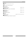
Table of Contents
Chapter 1 Unit’s Features and Structure ................................................................................................... 1
1.1 Unit’s name and Model numbers ............................................................................................................. 1
1.1.1 Main unit ......................................................................................................................................... 1
1.1.2 Options ........................................................................................................................................... 1
1.1.3 Software ......................................................................................................................................... 1
1.2 Unit’s Features ......................................................................................................................................... 2
1.2.1 System configuration of Data Logger Light .................................................................................... 2
1.2.2 Features of Data Logger Light........................................................................................................ 2
Chapter 2 Parts Name and Functions ........................................................................................................ 3
2.1 Parts Name and Functions ...................................................................................................................... 3
2.2 Symbol List .............................................................................................................................................. 6
Chapter 3 Communication Specifications .................................................................................................. 7
3.1 Communication specifications ................................................................................................................. 7
3.2 Caution for RS485 communication .......................................................................................................... 8
Chapter 4 Memory Specifications .............................................................................................................. 9
4.1 SD Memory Card ..................................................................................................................................... 9
Chapter 5 Installation and Wiring ............................................................................................................. 11
5.1 Installation .............................................................................................................................................. 11
5.1.1 Install space.................................................................................................................................. 11
5.1.2 How to install ................................................................................................................................ 12
5.1.3 Installation by using optional mounting plate ............................................................................... 12
5.2 Wiring ..................................................................................................................................................... 14
5.2.1 Wiring of power supply ................................................................................................................. 14
5.2.2 Grounding ..................................................................................................................................... 15
5.2.3 Wiring of terminal block ................................................................................................................ 16
5.3 Install and Setup of Backup Battery....................................................................................................... 19
5.3.1 How to install ................................................................................................................................ 19
5.3.2 Time for Replace of Backup Battery ............................................................................................ 19
5.3.3 Life of Backup Battery .................................................................................................................. 19
5.4 Safety Measures .................................................................................................................................... 20
5.4.1 Safety measures .......................................................................................................................... 20
5.4.2 Momentary power failures ............................................................................................................ 20
Chapter 6 Setup Procedure of Configurator DL....................................................................................... 21
6.1.1 How to install ................................................................................................................................ 21
6.1.2 How to uninstall ............................................................................................................................ 23
6.1.3 USB Driver.................................................................................................................................... 24
6.1.4 Before setup ................................................................................................................................. 25
6.1.5 Easy-setup.................................................................................................................................... 26
6.1.6 Wizard setup................................................................................................................................. 30
6.1.7 Manual-setups .............................................................................................................................. 35
Chapter 7 About Configurator DL............................................................................................................. 42
7.1 About Configurator DL ........................................................................................................................... 42
7.2 Explanation of each menu ..................................................................................................................... 42
7.2.1 Top menu ..................................................................................................................................... 42
7.2.2 Manual-setups Menu .................................................................................................................... 43
7.2.3 Setup of Data Logger Lights’ name and destination to save ....................................................... 46
7.2.4 Logging file setup ......................................................................................................................... 47
7.2.5 Logging device registration .......................................................................................................... 50
7.2.6 Data setups .................................................................................................................................. 56
7.2.7 Mail sending setup ....................................................................................................................... 60
7.2.8 Transmit to Data Logger Light and Read out from Data Logger Light (Access to Main unit) ...... 62
7.2.9 Password setup ............................................................................................................................ 64
7.2.10 LAN port setup ........................................................................................................................... 65
7.2.11 RS232C/RS485 setup ................................................................................................................ 72
7.2.12 Details of data to be logged........................................................................................................ 74
7.2.13 Trigger setup .............................................................................................................................. 78
7.2.14 Configuration .............................................................................................................................. 83
7.2.15 Easy-setup.................................................................................................................................. 95
7.2.16 Wizard setup............................................................................................................................. 102
7.2.17 Firmware update ...................................................................................................................... 106
7.2.18 Status view ............................................................................................................................... 107
7.2.19 Current value monitor ............................................................................................................... 109
7.2.20 Logging file list .......................................................................................................................... 110
Chapter 8 About Creating File................................................................................................................ 112
8.1 Creating file .......................................................................................................................................... 112
8.1.1 Logging file ................................................................................................................................. 112
8.1.2 System history file ...................................................................................................................... 115
8.1.3 Trigger history file ....................................................................................................................... 121
Chapter 9 Communication...................................................................................................................... 125
9.1 MEWTOCOL Communication .............................................................................................................. 125
9.1.1 Overview of MEWTOCOL-COM................................................................................................. 125
9.2 MODBUS(RTU) Communication ......................................................................................................... 127
9.2.1 Overview of MODBUS(RTU) ...................................................................................................... 127
9.3 FTP (File Transfer Protocol) communication ....................................................................................... 129
9.3.1 Outline of FTP(File Transfer Protocol) ....................................................................................... 129
Chapter 10 Example of Connecting to Data Logger Light ..................................................................... 130
10.1 Connect Eco-POWER METER .......................................................................................................... 130
10.2 Connect Visualization Software ......................................................................................................... 131
10.2.1 KW Watcher ............................................................................................................................. 132
10.2.2 Connect Programmable Display............................................................................................... 133
Chapter 11 Registers ............................................................................................................................. 134
11.1 Internal Relay・Register ..................................................................................................................... 134
11.1.1 Data registers ........................................................................................................................... 134
11.1.2 Special Internal Relay (R) ........................................................................................................ 135
11.1.3 Special Data Register (DT) ...................................................................................................... 136
Chapter 12 Self-diagnostic and Troubleshooting................................................................................... 139
12.1 Self-diagnostic Function .................................................................................................................... 139
12.1.1 LED Display for Status Condition ............................................................................................. 139
12.2 Troubleshooting ................................................................................................................................. 140
12.3 Error Code ......................................................................................................................................... 142
12.3.1 Hard error code ........................................................................................................................ 142
12.3.2 Network error code ................................................................................................................... 142
12.3.3 Communication error code ....................................................................................................... 144
12.3.4 File error code .......................................................................................................................... 145
Chapter 13 Specifications ...................................................................................................................... 146
13.1 General Specifications ....................................................................................................................... 146
13.2 Performance Specifications ............................................................................................................... 147
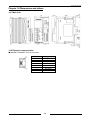
Chapter 14 Dimensions and others........................................................................................................ 148
14.1 Main Unit ............................................................................................................................................ 148
14.2 Ethernet communication .................................................................................................................... 148
14.3 BIN/HEX/BCD Codes ........................................................................................................................ 149
14.4 ASCII Codes ...................................................................................................................................... 150
Data Logger Light
Cautions before using
■ Installation environment (Use within the normal specifications.)
・Ambient temperature: -10 to 50 °C.
・Ambient humidity: 30 to 85 % RH (at 20℃, non-condensing)
・Pollution degree: 2
・Keep the height below 2000m.
・Do not use in the following environments.
-Where the unit will be exposed direct sunshine
-Where sudden temperature changes causing condensation.
-Where inflammable or corrosive gas might be produced.
-Where the unit will be exposed airborne dust, metal particles or saline matter.
-Where organic solvents such as benzene, paint thinner, alcohol, or strong alkaline solutions
such as ammonia or caustic soda might adhere to the product
-Where direct vibration or shock might be transmitted to the product, and where water might
wet the product
- Where high-voltage line, high-voltage device, power line, power supply device or the device
with sending part such as amateur radio are existed, or large switching surge is occurred.
(Min.100mm)
■ Installation
・Installation and wiring must be performed by expert personnel for electrical work or
electric piping.
■ Static electricity
・Discharge static electricity touching the grounded metal etc. when you touch the unit.
・Excessive static electricity might be generated especially in a dry place.
■ Unit’s case
Although fire-retardant resin is used for the main case, do not install at the side of flammable
item. In addition, do not place on the flammable item.
■ Power supplies
・If using a power supply without a protective circuit, power should be through a protective
element such as fuse.
・If an incorrect voltage is directly applied, the internal circuit may be damaged or destroyed.
■ Before power on
Please note the following points when turning on power at the first time.
・Confirm there are neither wiring rubbish nor especially an electrical conduction when installed.
・Confirm neither the power supply wiring and the power-supply voltage are wrong.
・Tighten the installation screw and the terminal screw surely.
・Set RUN/STOP mode change switch to STOP.
■ Request concerning setting parameters storage
To prevent the accidental loss of setting parameters, the user should consider the following
measures.
To avoid accidentally losing setting parameters, destroying files, or overwriting the contents of
files, created setting files should be backed up or the contents should be printed out and then
saved.
The password setting is designed to avoid settings being accidentally changed. If the
password is forgotten, however, it will be impossible to change the settings. When specifying
the password, note it in the specifications or in another safe location in case it is forgotten at
some point.
i
Data Logger Light
■ Precautions on using networks
・If the product is used with networks for the applications which might lead to death or financial loss, it
is recommended that you should take safety measures on designing the system, and by conducting
double circuits and so on.
・This product supports various network connections such as internet, intranet or telephone network,
however, we have no responsibility for the delay or inability of the operation caused by the failures
of terminal equipments, communication service by telecommunication carriers or interruption of
network, or errors in transmitting means, which are not our responsibility.
・If you make up system using various networks such as internet, intranet or telephone network, it is
recommended to take measures for protecting against information leak, interception and
unauthorized access according to your network and application.
・Identification is necessary with a user name and password to gain access to this unit. Change the
user name and password regularly in order to prevent the information from leaking.
・We do not accept liability for the following cases.
1) Guarantee for any kind of damages to the things/products, caused by physical defects of the
product.
2) When the other conditions than the ones specified in these specifications exist for handling,
storage and transportation of the product after the delivery.
3) When damage is caused by the unpredictable phenomena with the technique that was practiced
before the product delivery.
4) When damage is caused by natural disasters such as an earthquake, flood, fire, war and artificial
disasters.
5) When necessary countermeasures are not taken to establish a system despite the precautions
described in this specifications.
■Cautions
・When it power on first time or it turns off power and battery for long time, initialize the internal
memory (push rest switch for 5 seconds or more) before write setup data to Data Logger Light.
And set time with calendar timer setup for using logging function.
・When transmitting setup data to Data Logger Light, take care not to overwrite the setup.
・When using the internal memory, be sure to connect backup battery.
ii
Data Logger Light
Chapter 1 Unit’s Features and Structure
1.1 Unit’s name and Model numbers
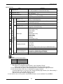
1.1.1 Main unit
Product name
Data Logger Light
1.1.2 Options
Product name
FP0 mounting plate
(Slim type) (10pcs.)
FP0 mounting plate
(Flat type) (10pcs.)
Battery for FP∑ (attached)
Terminal driver
Model No.
AKL1000
Description
Mounting plate to mount on a panel
vertically.
Mounting plate to mount on a panel
horizontally.
Required for storing collected data and
holding the calendar timer function
Use to wire the terminal (Phoenix)
Model No.
AFP0811
AFP0804
AFPG804
AFP0806
1.1.3 Software
Name
Configurator DL *1
Description
Remarks
Free of charge
Setup software
Tool for searching IP address
Free of charge
Configurator WD
(Ver.1.50 or more)
*2
Tool for format SD memory card
Free of charge
SD Formatter
*1 You can download from our website.(http://www3.panasonic.biz/ac/e/index.jsp)
(Member registration is necessary, free of charge.)
*2 You can download from Panasonic HP. (Member registration is not necessary, free of charge.)
*1
1
Data Logger Light
1.2 Unit’s Features
1.2.1 System configuration of Data Logger Light
PC
LAN
Data Logger Light
SD memory card
USB
PC(Configurator DL)
RS232C
24VDC
RS485
RS485/232C
PLC・Wireless sensor etc.
Display
Eco-POWER METER ・ PLC
1.2.2 Features of Data Logger Light
Data Logger Light has 3 features.
1) ALL in One
Data Logger Light has AC free power supply and communication port (RS232C/RS485) inside,
therefore it is possible to save wiring or installing process.
It is possible to use without SD memory card by using internal memory (SRAM).
Note
Internal memory (SRAM) can be used up to 1MB.
Reference
<4.1 SD memory card>
2) Data collecting and logging
Data Logger Light can collect and log relay status (Inst.value (ON/OFF)), accumulated ON time,
register value (Inst.value, Ave.value etc.) and so on.
Logging data can be saved in the internal memory (SRAM) or SD memory card as csv.
3) Setup software “Configurator DL”
Data Logger Light can be set with PC by using “Configurator DL”.
Setup data can be written and read only by connecting PC and Data Logger Light with USB cable.
Note
In order to use USB, USB driver is necessary.
Reference
<Chapter 6 Setup Procedure of Configurator DL>
2
Data Logger Light
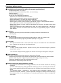
Chapter 2 Parts Name and Functions
2.1 Parts Name and Functions
①SD memory card cover
Open SD memory card cover to insert or remove SD memory card.
After inserting SD memory card, close the cover. If the cover is not closed correctly, it can’t access
SD memory card and can’t read nor write.
*When removing SD memory card, open the cover and confirm that the access LED lights off.
②SD memory card slot
Insert SD memory card.
*Be sure to the direction when inserting.
If it is inserted with wrong direction, the unit or
SD memory card may be broken.
③SD memory card access switch
The switch is ON by closing SD memory card
cover and it becomes to access to SD memory card.
*The switch is possible to set ON/OFF by “Configurator DL”.
④Power supply connector/
Service power supply connector
■Power supply connector
Supply 100 to 240VAC.
■Service power supply connector
It can use at 24V DC (0.2A).
L
N
INPUT
100~240V AC
F.G.
Frame Ground
+
-
OUTPUT
24V DC
0.2A
Note
Do not supply 100 to 240V AC to service power supply connector (24V DC).
3
Data Logger Light
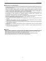
⑤RUN/STOP mode change switch
It changes the working mode of Data Logger Light.
Switch
Mode
RUN (top)
RUN mode :Collecting and logging data
STOP (bottom)
STOP mode: Stop collecting and logging data
*You can change RUN/STOP mode by “Configurator DL”.
⑥Reset switch
Use to initialize all setup.
Push reset switch for 5 or more seconds during power on, and setup data and measurement data are
initialized.
Note
Do not push the reset switch strongly. It might be broken.
⑦USB port (for USB 2.0)
Connect USB cable.
Use to connect to PC for using “Configurator DL”.
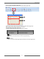
⑧Status indicator LED
It shows the working status of Data Logger Light.
⑨SD access indicator LED
It shows the status of access to SD memory card.
⑩Communication status indicator LED
It shows the communication status of RS232C/RS485.
LED
MODE (Green)
⑧
TRIGGER (Green)
ERROR (Red)
⑨
SD (Green)
Lights
Flashes
Lights
Lights
Flashes
Lights
Flashes
OFF
Status of LED and working
RUN mode: Collecting and logging data
STOP mode: Stop collecting and logging
Trigger occurs
Error occurs
Inserting SD memory card
Accessing to SD memory card
SD memory card is not inserted.
Vacant
S (Green)
Flashes
Transmitting data
R (Green)
Flashes
Receiving data
S (Green)
Flashes
Transmitting data
R (Green)
Flashes
Receiving data
RS232C
⑩
RS485
4
Data Logger Light
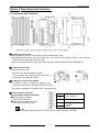
⑪Ethernet connecting connector (RJ45)
Use for Ethernet communication.
Communication status LED
100BASE-T/10BASE-TX RJ45 connector
Pin No.
1
2
3
4
5
6
7
8
1
SPEED
LED
LINK/ACT
LED
8
・Initial value
IP address
Subnet mask
Default gateway
192.168.1.5
255.255.255.0
192.168.1.1
・Status of LED and working
LED
Working
SPEED LED
Shows communication speed
(top)
LINK/ACT LED
(bottom)
Signal
TX+
TXRX+
No use
No use
RXNo use
No use
Shows communication status
Status
Lights
Flashes
Lights
Flashes
Working status
100BASE communication
10BASE communication
Linking
Transmitting/Receiving data
⑫Communication terminal
Use to connect serial communication RS232C/RS485.
No.
Functions
①
②
③
④
⑤
⑥
⑦
⑧
①
②
SD
RS232C
RD
③
SG
④
+
⑤
⑥
⑦
⑧
-
RS485
+
-
E
⑬DIN hook
Install to DIN rail by one-touch.
Use to install to the mounting plate slim type (AFP0811).
⑭Battery cover
Remove this cover in order to install the attached backup battery.
Using the battery can backup calendar timer and internal memory data.
Reference
<5.3 Install and Setup of Backup Battery>
⑮Hook
Use to mount and fix FP0 mounting plate flat type (AFP0804).
5
Data Logger Light
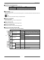
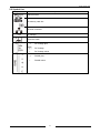
2.2 Symbol List
Symbol
Explanation
USB connector
SD memory card slot
Ethernet connector
AC Voltage
Protective earth
+
DC Voltage plus
DC Voltage
-
DC Voltage minus
+
RS485 plus
-
RS485 minus
6
Data Logger Light
Chapter 3 Communication Specifications
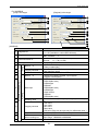
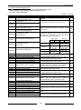
3.1 Communication specifications
a) Interface: Ethernet communication
Item
Interface
Connector shape
Transmission speed
Transmission Transmission method
Max. segment length
Transmission cable
Protocol
Functions
Specification
IEEE802.3u,100BASE-T/10BASE-TX
RJ45
100Mbps / 10Mbps
Base band
100m
UTP (Category 5)
TCP/IP
Auto-negotiation
MDI / MDI-X Auto-crossover
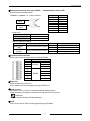
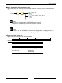
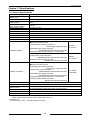
b) Interface: RS232C, RS485
Item
Specification
Interface
RS232C
RS485
Transmission type
1:1
1:N
Connected number
1
99 *1 *2
Communication method
Half-duplex
Synchronous method
Asynchronous communication method
Transmission distance
15m
Max. 1200m *3
Transmission speed
4800,9600,19200,38400,57600,115200bps
Data length
7bit / 8bit
Transmission
Parity
Odd / Even / None
format
Stop bit
1bit / 2bit
Protocol
MEWTOCOL, MODBUS(RTU)
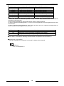
*1 In case of using PC as a slave, we recommend SI-35 and SI-35USB (from LINE EYE Co., Ltd.).
*2 When using SI-35, SI-35USB or PLC from our company (which can be connected up to 99 units),
up to 99 Eco-POWER METER can be connected. In case using this system with the other devices,
up to 31 Eco-POWER METER can be connected.
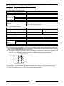
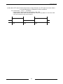
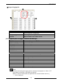
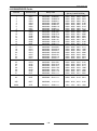
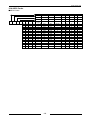
*3 Transmission distance is limited as below according to transmission speed and connected unit
number. Under 38400bps, maximum distance is 1200m and maximum unit is 99 units.
Transmission speed: 15.2kbp
Transmission speed: 57.6kbps
99
Unit number
70
40
0
700
1000 1200 (m)
Transmission distance
*4 MEWTOCOL is received with port of 9094 and 9095. (Port number can be changed by setting.)
*5 In case of that the unit No. is “%EE”, Data Logger Light is the target.
7
Data Logger Light
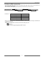
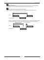
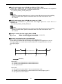
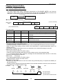
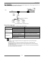
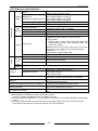
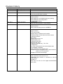
3.2 Caution for RS485 communication
When Data Logger Light communicates with RS485, Data Logger Light occupies communication line
for a period after sending data.
Start sending to Data Logger Light after passing the below time by receiving device.
t
Data Logger Light
Connected device
Send
Send
Response
Response
T
Condition of “t”
T
Communication condition
4800bps
9600bps
19200bps
38400bps
57600bps
115200bps
T
4.2ms or more
2.1ms or more
1.1ms or more
0.6ms or more
350μs or more
200μs or more
Some of our PLCs have SYS1 command that enables to change time after receiving a command until
a response is returned.
*When it can’t communicate, it will retry one time with setting retry time.
Reference
<FP Series Programming Manual ARCT1F313E>
8
Data Logger Light
Chapter 4 Memory Specifications
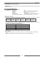
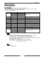
4.1 SD Memory Card
SD memory card I/F specifications
Item
Specifications
Slot
SD and SDHC
Capacity
Max. 32GB
Speed class
Class2 to Class10
Format type
FAT, FAT32
*If it breaks down during writing, there is a possibility that the data is damaged.
We recommend using UPS (uninterruptible power system).
Note
・It does not recognize SD memory card with 32GB or more capacity.
・In order to format SD memory card, use Panasonic format software.
You can download from Panasonic website.
File system of SD memory card formatted by PC’s software is not supported SD memory
card standard generally.
■Confirmation of the working
We confirmed the working of the below SD memory cards, however, it is not guaranteed all workings,
Manufacturer
Capacity
Part number
RP-SDF02G
2GB
RP-SDF02GCD1
RP-SDF04G
Panasonic
4GB
RP-SDF04GCD1
RP-SDF08G
8GB
RP-SDF08GCD1
(As of February 2014)
■Insert and remove SD memory card
・After inserting SD memory card, be sure to close the cover.
If the cover is not closed, it will cause the access error and can’t read nor write SD memory card.
・Opening the cover and turn on the access LED, remove SD memory card.
(It accessed SD memory card during flashing the LED.)
*It can be set the switch’s working by using “Configurator DL”.
9
Data Logger Light
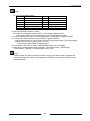
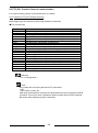
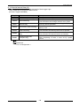
[Guide of saved file number]
Connect 99 units 15 min.cycle logging 1 file per 1 day → about 80KB
SD memory card capacity
File number
2GB
About 26,214 files
4GB
About 52,428 files
8GB
About 104,857 files
32GB
About 419,430 files
1MB (internal memory)
About 12 files
Note
・The file number is decreased according to capacity of “System.csv”
and “Trigger.csv”.
・While SD access LED is blinking, do not remove SD memory card.
It might damage data in SD memory card and SD memory card.
・The max saving file number differs according to the using conditions.
10
Data Logger Light
Chapter 5 Installation and Wiring
5.1 Installation
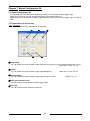
5.1.1 Install space
■Panel installing space
・Leave at least 50 mm of space between the wiring ducts of the unit
and other devices to allow heat radiation and the unit replacement.
50mm or more
Data
Logger
Light
50mm or more
・Keep at least 100mm of space between devices to avoid adverse affects from noise or heat when
installing a device or panel door to the front of the unit.
Leave at least 100mm of space from the front surface of the unit in order to allow room for wiring.
100mm or more
Panel door
Data
Logger
Light
Other
device
・Do not install on the top of the devices with high heat generation such as heater, transformer,
high-capacity register and so on.
■For heat discharge
・Do not install the unit as shown below.
Horizontal
Face down
Face up
Upside-down
11
Data Logger Light
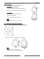
5.1.2 How to install
■Attach to DIN rail and remove from DIN rail
You can attach to DIN rail by one-touch.
How to install
①Fit the upper hook onto DIN rail.
*Check that DIN hook is set to DIN rail completely .
②Press on the lower hook without moving the upper hook.
How to remove
①Insert a flathead screwdriver to DIN hook.
②Pull down the DIN hook.
③Lift up the unit and remove from the rail.
Note
Be sure to fix by 2 points of DIN hooks.
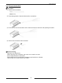
5.1.3 Installation by using optional mounting plate
■When using FP0 mounting plate slim type (AFP0811)
Use M4 size screws and install according to the below dimensions.
The rest of procedure is the same as to attach to DIN rail.
Note
It can mount with one mounting plate.
Mount to DIN hook of left side from the back.
12
Data Logger Light
■When using FP0 mounting plate flat type (AFP0804)
Use M4 size screws and install according to the below dimensions.
Raise the expansion hook of the unit. Align it with the mounting plate and press the hooks.
Note
Mounting plate flat type (AFP0804) should be used with only one Data Logger Light.
13
Data Logger Light
5.2 Wiring
5.2.1 Wiring of power supply
■Wiring of power supply
Be sure to wire correctly according to the terminal arrangement and wiring diagrams.
After completing wiring, be sure to attach the terminal cover for safety reasons.
Check that the connected power supply voltage is in the range of the allowable power supply.
Rated input voltage
Allowable voltage
Rated frequency
Allowable frequency
100 to 240VAC
85 to 264VAC
50/60Hz
47.5 to 63Hz
Note
・To add voltage or frequency out of specification range or to use wire that is not allowable
cause damage to power supply.
・Do not connect AC power supply 100-240V to service power supply terminals.
■Isolate power supply system
Isolate the wiring system to Data Logger Light, input/output devices, and mechanical power
apparatus.
DLL
To avoid the effect from noise
Use power supply that has little noise. The inherent noise resistance is sufficient for power supply
superimposed noise. However, we recommend decreasing noise by using insulated transformer.
In order to decrease influence from noise, use twist cable for power supply.
14
Data Logger Light
6.6mm or less
6.6mm or less
■Power supply terminals
1) Terminal fastening torque should be 0.8 to
3.7mmφ
3.7mm
1.0N・m. In case of using a crimping terminal,
use it with insulating sleeve applicable to
M3.5.
2) To protect the devices, it is necessary to
install power switch and circuit breaker in the power supply circuit.
3) We recommend a wire with the cross section of 0.75 to 1.25 mm2 and the length of 10m or less for
power supply line and service power line.
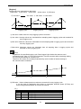
5.2.2 Grounding
■In case of excess noise
Under normal conditions, the inherent noise resistance is sufficient. However, in case of that it is used
under the excess noise, ground the unit to increase noise suppression.
■Exclusive grounding
・For grounding purposes, use wire with the cross section of 2.0mm2 or more and the resistance of
less than 100Ω.
・The grounding point should be as close to Data Logger Light as possible. And the grounding wire
should be as short as possible.
・If the ground point shares with the other device, it may occur an adverse effect. Always use an
exclusive ground for each device.
○CORRECT
Data Logger
Light
×INCORRECT
Data Logger
Light
Other device
(Inverter etc.)
15
Other device
(Inverter etc.)
Data Logger Light
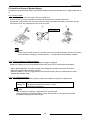
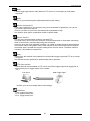
5.2.3 Wiring of terminal block
■How to wire
① Remove wire’s insulation.
9mm(±1mm)
② Press orange switch of terminal block with an screwdriver.
③ Insert wire into the terminal block until it reaches the back of the block with pressing the switch.
④ Remove the screwdriver from the switch.
■Notes for wiring
Take care not to break wire.
・When removing wire’s insulation, take care not to scratch core wire.
・Do not twist the wires to connection.
・Do not solder wire to connect them. Soldering may break due to vibration.
・After wiring, do not make stress to the cable.
16
Data Logger Light
■Attached terminal block socket
The terminal block manufactured by Phoenix Contact is used.
Phoenix Contact Model No.
Number of pin
Model No.
Product No.
8-pin
FK-MCP1,5/8-ST-3,5
1939963
Suitable wire (Twisted wire)
Size
Nominal cross-sectional area
AWG#28 to 16
0.14mm2 to 1.5mm2
Suitable pole terminal without insulation sleeve
If using a pole terminal, use the following model.
Manufacture
Cross-sectional area
Size
Model No.
0.34mm2
AWG#22
AI 0,34-12TQ
Phoenix Contact
Co.
2.5mm2
AWG#14
AI 2,5-12BU
Pressure welding tool for pole terminal
Phoenix Contact Model No.
Manufacture
Model No.
Model No.
Phoenix Contact
CRIMPFOX UD 6-4
1205244
Co.
■Recommended cable
Use the transmission cables shown below for transmission line.
Conductor
Insulator
Resistance
Cable
Material
Thickness
Size
(at 20℃)
Twistedpair
with shield
VCTF
1.25 mm2
(AWG16)
or more
Max.16.8Ω/km
Polyethylene
Max.
0.5 mm
Approx.
8.5 mm
0.5 mm2
(AWG20)
or more
Max.33.4Ω/km
Polyethylene
Max.
0.5 mm
Approx.
7.8 mm
0.75 mm2
(AWG18)
or more
Max.25.1Ω/km
PVC
Max.
0.6 mm
Approx.
6.6 mm
Cable
Section
Shield
Twisted-pair
with shield
Conductor
Jacket
Insulator
Jacket
VCTF
Cable
diameter
Conductor
Insulator
17
Applicable cable
HITACHI
KPEV-S
1.25 mm2×1P
Belden Inc. 9860
HITACHI
KPEV-S
0.5 mm2×1P
Belden Inc. 9207
VCTF
0.75 mm2×2C
(JIS)
Data Logger Light
Note
・Use shielded type twist cables.
・Use only one type of the transmission cable. Do not mix the different type of cable.
・Use twist pair cables under a bad noise environment.
・When using shielded cable for RS485 transmission line, ground one end. If it ground
both end, it doesn’t communicate correctly.
・Use a class D dedicated earth for grounding. Do not share a ground with other earth lines.
・Be sure to connect with daisy chain the RS485 transmission line between each unit.
Do not use a splitter.
18
Data Logger Light
5.3 Install and Setup of Backup Battery
Installing an optional backup battery (AFPG804) enables to back up calendar timer, logging data and so
on.
5.3.1 How to install
①Open the battery cover by using a driver or similar tool.
②Connect the connector and place it between the bosses as to insert the terminals.
③Insert the code between the connector and the battery and attach the battery cover from the top.
*Be careful not to clip code between the cover and case.
①
②
③
Two bosses
Note
When using internal memory or calendar, be sure to install the battery and set the function
of check battery voltage by “Configurator DL”. <Configuration-Check battery voltage>
5.3.2 Time for Replace of Backup Battery
Error LED on the unit will flash when the battery voltage is dropped.
Replace the battery as soon as possible because the error LED is not detected immediately.
・When replacing battery, turn off the power after supplying the power more than 30 minutes.
After that, replace battery within 2 minutes.
・When the battery is run out, logging data in the internal memory will be undefined and it might
initialize the calendar timer.
5.3.3 Life of Backup Battery
It is necessary to replace battery regularly. Refer to the below for a guide of replace time.
Battery life
250 days or more (In actual use: approx. 2 years(25℃))
(Suggested replacement interval: 1 year)
(No power is supplied.)
Note
Risk of explosion if battery is replaces by an incorrect type.
When disposing the replacing battery, follow the direction of using area and insulate
the battery using tape for terminal part.
19
Data Logger Light
5.4 Safety Measures
5.4.1 Safety measures
■Confirm the Grounding
When installing Data Logger Light next to devices that generate high voltage from switching such as
inverters, do not ground them together. Use an exclusive ground for each device.
■In order to prevent from electrical shock, be sure to use terminal cover.
5.4.2 Momentary power failures
■Working when momentary power failure
If the period of power failure is less than 10ms, Data Logger Light continues to the working.
In case of that the period is more than 10ms, the working is changed depending on the conditions
such as combination of unit, power supply voltage and so on.
20
Data Logger Light
Chapter 6 Setup Procedure of Configurator DL
“Configurator DL” is the application software in order to use for setup of Data Logger Light.
There are 3 ways to setup by “Configurator DL”.
・Easy-setup : You can setup only selecting logging cycle, Unit No. and connected unit.
(Refer to 6.1.5)
・Wizard : You can setup dialogically.
(Refer to 6.1.6)
・Manual-setup : You can setup from the beginning. Therefore you can setup detail.
(Refer to 6.1.7)
6.1.1 How to install
It is necessary to install “Configurator DL” to your PC.
Point
You can download “Configurator DL” from our website.
Member registration is necessary. Free of charge.
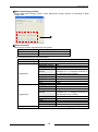
■Operating environment
Item
PC
OS (only 32-bit editions)
Required hard disc capacity
CPU
Loaded memory
Image resolution
Display colors
Communication form
Specification
IBM PC/AT compatible machine
Windows Vista Business, Windows 7 Professional/Home Premium,
Windows 8, Windows 8.1
10Mbyte (not include the capacity of saving setup data)
PentiumⅢ 700MHz or more
512MB or more
1024x768 or more
High Color (32-bit or more)
USB2.0, LAN
Note
Even if a customer stores a file created by the customer in ¥Program files, the file will be
automatically stored in /userID/AppData/Local/VirtualStore.
[When User Account Control (UAC) is on as the default setting of Windows VistaTM]
21
Data Logger Light
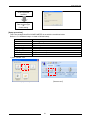
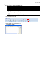
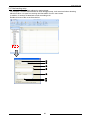
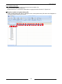
How to install (*This is image of Windows 7.)
1) Execute setup file (configdl_freev***.exe).
Note
“***" in file name means version of the file. Confirm version before downloading from our
website. (ex. Ver.100 -> configdl_freev100j.exe)
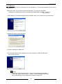
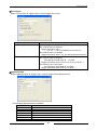
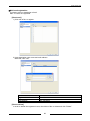
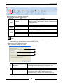
2) Click “Next(N)” and the window below is displayed.
Read license agreement and click “Yes” when you agree.
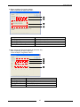
3) Enter user name and company name and click “Next”.
22
Data Logger Light
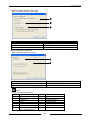
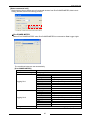
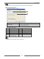
4) Specify the install destination and click “Next”.
Initial install folder is “C:¥Program Files¥Panasonic-EW Control”.
If no change, click “Next”. When you’d like to change, click “Browse” and select install destination.
After that, click “Next”.
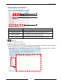
5) Select program folder name.
Initial is “Panasonic-EW Control”. If no change, click “Next.
It starts installing and installs “Configurator DL” to the PC.
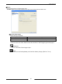
6.1.2 How to uninstall
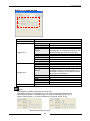
When uninstalling, select “Control Panel -> Add or Remove programs
->Panasonic-EW Control Configurator DL” and remove.
23
Data Logger Light
6.1.3 USB Driver
When Data Logger Light is connected to PC and powered on, "Found New Hardware Wizard" will be
started on PC.
USB driver name: If you install to the initial destination, you can find in this folder.
C:¥Program Files¥Panasonic-EW Control¥Configurator¥DL¥DLL USB¥DL_VUART.inf
¥ dl_vuart.cat
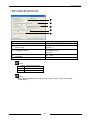
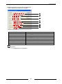
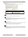
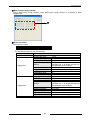
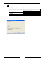
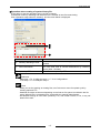
1) After starting “Found New Hardware Wizard” wizard, check "No, not this time” and click “Next”.
2) Specify the folder saved USB driver.
3) It starts installing the USB driver.
4) The message below will be displayed and it will complete to install the USB driver.
Click “Finish” to finish.
Note
According to the using environment, it may not start wizard automatically.
In this case, select “Control Panel -> System -> Device Manager” and install.
(Check beforehand it may be different according to using OS”)
24
Data Logger Light
6.1.4 Before setup
Before setups, do the followings.
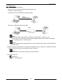
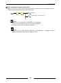
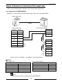
1) Connect PC to be used for setups with Data Logger Light.
There are 2 ways to connect.
①Directly connect via USB cable or Ethernet cable.
USB or
Ethernet cable
②Connect via Ethernet cable using HUB.
HUB
Note
・When using USB, install the driver attached “ConfiguratorDL”. (Refer to 6.1.3)
・In the case of use, the setting of the personal computer please do not make Configurator
DL "a standby mode" or "a sleep mode".
Point
Both of cross cable and straight cable can be used for Data Logger Light to connect Ethernet
connector to PC.
2) When it is powered on first time or the power and battery are off for long time, initialize the internal
memory (Press and hold the reset switch in power-on state).
Note
Do not push the reset switch strongly. It might be broken.
3) Set time to the unit.
Reference
<7.2.14 Configuration >
25
Data Logger Light
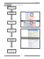
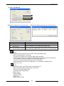
6.1.5 Easy-setup
You can setup Data Logger Light by simple setting.
This is the example of the setup procedure for selecting “Connecting unit: Eco-POWER METER”.
Refer to <7.2.15 Easy-setup> in detail of Easy-setup such as setup for “Multi-circuit energy checker”,
“Multi-circuit energy monitor” and “Multi-circuit energy monitor”
Note
It set only for MEWTOCOL.
[Setup flowchart]
Start Configurator DL.
Select “Easy-setup” icon.
Execute “Easy-setup”
Can be executed
with [Home menu].
[Top menu]
Select “Logging cyc.”
Select Unit No. to use
Transmit settings to
Data Logger Light
or
Finish setting
In order to transmit the settings, check box of
“Transmit this settings” and click “OK”.
When not transmitting the settings, click “OK” without
check.
26
Data Logger Light
[Setup procedure]
This is the example that Eco-POWER METER is set.
Item
Logging trigger
15 min cycle
Unit No.
1
Contents
1) Click icon of “Easy-setup” in menu.
[Top menu]
[Home menu]
2) Select logging cycle.
Select logging cycle of collecting data from 15 min., 30 min. and 60 min.
In this example, select 15 min. cycle.
27
Data Logger Light
3) Select using unit No.
Set the unit No of Eco-POWER METER connected Data Logger Light.
In this example, check “01”.
4) In order to transmit the settings to Data Logger Light, check box of “Transmit this settings” and
click “OK”. When it is not transmitted to Data Logger Light, click “OK” without check.
It shifts to home window of “Configurator DL”.
Reference
As to the transition procedure, refer to <7.2.8 Transmit to Data Logger Light and Read out
from Data Logger Light (Access to Main unit)>
Note
When you click “OK” after setup, setup data with “Configurator DL” is cleared. When you
don’t want to clear the setup data, save setup data before transmitting the setup.
28
Data Logger Light
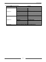
The items below are set automatically.
Item
Contents
New file create timing
Everyday 00:00:05
Logging file name
Syunji
Saved file number
60
Data type
Register
Device
DT:100 (Integrated electric power)
Logging file 1
Data type
DEC2W(No code)
Logging contents
Inst.value
Digit
0
Conversion value
0.01
Unit
kWh
Logging file name
Sabun
Saved file number
60
Data type
Register
Device
DT:100(Integrated electric power)
Logging file 2
Data type
DEC2W(No code)
Logging contents
Diff.value
Digit
9
Conversion value
0.01
Unit
kWh
Configuration
Make the destination folder name of logging file [CF].
29
Data Logger Light
6.1.6 Wizard setup
You can setup Data Logger Light dialogically.
Note
It set only for MEWTOCOL. You can setup the items except 64 bit integer (DEC4W).
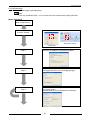
[Setup flowchart]
Start Configurator DL.
Select “Wizard” icon.
Execute “Wizard”
Can be executed
with [Home menu].
[Top menu]
Step 1
Step 1:
Set name, IP address, and data saved place.
Step 2
Step2:
Set logging file name (csv) and logging trigger.
Step 3
Step 3:
Set logging device
*Several devices can be registered if necessary.
30
Data Logger Light
Confirmation display
of the registered
contents
Transmit settings to
Data Logger Light
or
Finish setting
[Setup procedure]
This is the example that Eco-POWER METER is set with the conditions below.
Refer to <7.2.16Wizard setup> in detail of Wizard setup.
Item
Main unit name
IP address
Data saved place
Logging file name
Logging trigger
Logging device name
Collecting data
Unit No.
Contents
Data Logger Light
192.168.1.5
SD memory card
sekisan
15 min. cycle
Integrated electric power
Integrated electric power
1
1) Click “Wizard” icon.
[Top menu]
[Home menu]
31
Data Logger Light
2) Set basic setup of Data Logger Light.
After completing the input, click “Next”.
①
②
③
Item
①
②
③
Contents
Input name
Set IP address
Select data saved place
Data Logger Light
192.168.1.5
Select “SD memory card”
3) Input setup about logging file.
After completing input, click “Next”.
①
②
①
②
Item
Set file name
Set logging cycle to file (logging trigger)
Note
*1 It can’t use the below letters.
letter
name
Yen
¥
/
Slash
Backslash
\
:
Colon
;
Semi-colon
.
dot
Half-width space
(only the beginning)
Contents
sekisan
*1
Select “15 min”.
letter
*
?
“
<
>
|
Name
Asterisk
Question mark
Double quotation
Inequality sign
Inequality sign
pipe
32
Data Logger Light
4) Input conditions about logging device.
After completing the input, click “Next”.
①
②
③
④
⑤
①
②
Item
Input logging device name
Set communication port and unit No. of
device to log.
③
Set logging device
④
Input conversion value
converted.
Input unit. (not required)
⑤
when
it
is
Contents
Integrated electric power *1
Communication port: COM2(RS485)
Unit No.: 1
DT100
DEC2W(No code)
Inst.value
Do
0.01
kWh
Note
*1 It can’t use the below letters.
letter
name
comma
,
Double quotation
″
Point
When click “Integrated electric power (Inst. value)”, items of ③④⑤ are input
automatically.
33
Data Logger Light
5) It displays the setup contents.
In order to transmit the settings to Data Logger Light, check box of “Transmit this settings” and
click “OK”. When it is not transmitted to Data Logger Light, click “OK” without check.
Reference
<7.2.8 Transmit to Data Logger Light and Read out from Data Logger Light (Access to
Main unit)>
Note
When you click “Complete” after setup, setup data with “Configurator DL” is cleared.
When you don’t want to clear the setup data, save setup data before transmitting
the setup.
34
Data Logger Light
6.1.7 Manual-setups
You can setup Data Logger Unit from the beginning.
[Setup flowchart]
Start Configurator DL.
Execute
“Manual-setups”
[Top menu]
Set trigger
[Home menu]
Select triggers for logging and creating logging file.
Set logging file
[Logging file setup]
Register logging
device
Set conditions for data collecting.
[Logging device registration]
Transmit settings to
Data Logger Light
or
Finish setting
35
Data Logger Light
[Setup procedure]
This is the example to set with the conditions below.
Item
Trigger name
15 min. cycle
Trigger Type
Fixed Cycle
Logging trigger
15 min.
Trigger Name
Midnight
Trigger Type
Appointed time
New file create timing
Everyday 00:00:05
Logging file name
sekisan
Logging device name
Integrated electric power
Unit No.
1
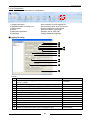
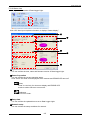
1) Click trigger setup icon to set.
2) Double-click any No.’s row from trigger list.
In this example, click No.1.
36
Contents
Data Logger Light
3) Setup conditions for logging trigger.
After completing all input, click “OK”.
①
②
③
④
①
②
③
④
Item
Trigger Name
Trigger Type
Trigger happening conditions
Cycle
Contents
Input “15 min. cycle”.
Select “Fixed Cycle”.
Select “Occur every hour on the hour”.
Input “15” and select “Min.”.
4) Next, setup new file create trigger in the same way.
After completing all input, click “OK”.
In this example, it registers in No.2.
①
②
③
④
①
②
③
④
Item
Trigger Name
Trigger Type
Type
Time
Contents
Input “Midnight”
Select “Appointed time”.
Select “Every day”.
Set “0:0:5”.
37
Data Logger Light
5) If the setup is finished correctly, logging trigger is displayed in No.1 and new file create trigger is
displayed in No.2.
Reference
<7.2.13 Trigger setup>
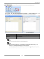
6) Setup logging file.
Click “Logging file setup” in Navigator menu and logging file list is displayed on the right.
Double-click any No.’s row to register.
In this example, click No.1.
38
Data Logger Light
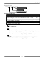
7) Setup each items to create logging file.
After completing all input, click “OK”.
①
②
③
④
①
Item
File name
②
Logging trigger No.
③
Saved file number
④
New file create timing
Contents
Input “sekisan”.
Select logging cycle.
Select trigger set at procedure 3) (Trigger No.:No.1)
Set the file number for logging file to save.
In this example, Set to “100”, max.value.
Select timing to create logging file.
Select trigger set at procedure 4) (Trigger No.:No.2)
Reference
<7.2.4 Logging file setup>
8) Setup for logging device registration.
Click one of the File No.1 to No.16 of “Logging device registration” in Navigator menu and logging
device registration list of selected file No. is displayed on the right.
In this example, No.1 is selected at 6), click “File No.1” and double-click the row of No.1 in the list.
39
Data Logger Light
9) Setup each items to logging device registration.
After completing all input, click “Register”.
①
②
③
④
⑤
⑥
⑦
⑧
①
②
③
④
⑤
⑥
⑦
⑧
Item
Register name
Communication I/F
Data Type
Device
Data style
Logging contents
Convert when creating csv
Unit
Contents
Input “Integrated electric power”
Select “COM2(RS485)”, “Unit No.1”
Select “Register”.
Input “DT 100” for “Integrated electric power”
Select “DEC2W (No code)”.
Select “Inst.value”
Input “0.01” for collecting an integrated electric power.
Input “kWh”.
Reference
< 7.2.5 Logging device registration >
40
Data Logger Light
11) Transmit setup data to Data Logger Light.
So far, all setup is completed, transmit setup data to Data Logger Light.
①
②
Select communication method and transmit the setup data to Data Logger Light.
After selecting communication methods, click “Execute”
It transmits setup data to Data Logger Light.
If it doesn’t transmit setup data, save the setup data as named.
Item
①
②
Use USB port
Use LAN port
Contents
Transmit data via USB port.
Transmit data via LAN port.
Note
Operation mode should be set to “STOP” during transmitting.
Reference
< 7.2.8 Transmit to Data Logger Light and Read out from Data Logger Light >
41
Data Logger Light
Chapter 7 About Configurator DL
7.1 About Configurator DL
“Configurator DL” is the application software in order to use for setup of Data Logger Light.
Install to your PC and you can set up Data Logger Light without main unit.
Setup data can be transmitted to Data Logger Light and read out from Data Logger Light via USB or
LAN.
7.2 Explanation of each menu
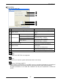
7.2.1 Top menu
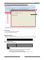
Start this software and the menu below is displayed.
①
④
②
③
⑤
①Easy-setup
You can make new setup of Data Logger Light only by selecting cycle of logging trigger and unit No.
(Refer to 6.1.5 and 7.2.15)
②Wizard
You can make new setup of Data Logger Light dialogically.
③Manual-setups
You can make new setup of Data Logger Light by input in detail.
④Read out from main unit
You can read out setup data from Data Logger Light.
⑤Open file
You can read out setup data from saved file.
42
(Refer to 6.1.6 and 7.2.16)
(Refer to 6.1.7)
Data Logger Light
7.2.2 Manual-setups Menu
Setup each item.
Click “Manual-setups” at top menu and it shifts to this menu.
Also when it finishes “Easy-setup” and “Wizard setup”, it shifts to this menu.
It shifts [Home] menu and [Online] menu by using tab.
■Home menu
Setup each item that is mainly collecting data.
⑤
⑥ ⑦
⑧
①
⑨
⑩ ⑪ ⑫ ⑬
②
③
④
⑭
⑮
①Menu
Setup items related setup file
②Menu shift
Shift [Home] menu and [Online] menu
③Easy-setup
Shift to Easy-setup window
(Refer to 6.1.5)
④Wizard
Shift to Wizard setup window
(Refer to 6.1.6)
⑤Transmit to Data Logger Light
Transmit setup data to Data Logger Light
(Refer to 7.2.8)
⑥Read out from Data Logger Light
Read out setup data from Data Logger Light
(Refer to 7.2.8)
⑦Password setup
Setup password that is used when data transmitting and data reading
(Refer to 7.2.9)
43
Data Logger Light
⑧Clipboard
Cut and copy and paste setup items in the list
⑨View
Setup to display or hide for each tool bar
⑩LAN port setup
Setup items for LAN port
(Refer to 7.2.10)
⑪RS232C/485 setup
Setup items for communication via RS232C/RS485
(Refer to 7.2.11)
⑫Trigger setup
Setup items for trigger
(Refer to 7.2.13)
⑬Configuration
Setup items for configuration
(Refer to 7.2.14)
⑭Navigator
Select item to register
(Refer to 7.2.3,7.2.4,7.2.5,8.1.2,8.1.3)
⑮Registration list
Select number to register and display list of registration
44
Data Logger Light
■Online menu
You can select menu that is mainly monitoring status of Data Logger Light.
① ② ③
④ ⑤
⑥
①Mode change
Change working mode of Data Logger Light (RUN/STOP)
Note
It can be switched regardless of the switch setting of Data Logger Light. However, it depends
on the switch setting of Data Logger Light after the update of firmware, update of setting file
or power activation.
②Setup initialize
Initialize setups that are set with software
③Update firmware
Update firmware of Data Logger Light
(Refer to 7.2.17)
④Status view
Display status of Data Logger Light
(Refer to 7.2.18)
⑤Current value monitor
Monitor the logging data currently
(Refer to 7.2.19)
⑥Logging file list
Display file list in SD memory card or internal memory.
(Refer to 7.2.20)
Note
・Notice that the setup data by setting with software is initialized when it executes “Setup initialize”.
・The version of firmware in Data Logger Light is updated when it executes “Update firmware”.
However, setup data are saved.
45
Data Logger Light
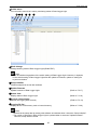
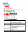
7.2.3 Setup of Data Logger Lights’ name and destination to save
You can set the name of Data Logger Light and select destination to save logging data.
①
②
[Shift window]
① Click “Data Logger Light” in Navigator.
② It shifts to “Main setup” window.
[Set main unit name]
Set name of Data Logger Light.
It displays the name when communication setup and when searching by “Configurator WD”.
Item
Name
Contents
Max. 32 letters
[Dest. of logging data]
Select destination of logging data.
Item
SD memory card
Internal memory (SRAM)
Contents
Save file in SD memory card
Save file in the internal memory (SRAM)
Note
・Capacity of the internal memory is 1MB. Install backup battery
when you’d like to use the internal memory.
・Be sure to check box of “Check battery voltage”
at “Configuration->Operation when occurring error” (Refer to 7.2.14)
46
Data Logger Light
7.2.4 Logging file setup
■Logging file
It setup at “Logging file setup” in Navigator.
Logging file is a file with the csv format according to logging trigger that the data collected from each
device (Eco-POWER METER, PLC etc.).
It is saved in SD memory card or internal memory.
①
②
③
④
⑤
⑥
⑦
Item
①
File name
②
Logging trigger No.
③
Collect DEC4W data
④
Saved file number
⑤
Operation when saved
file number is over.
⑥
New file create timing
⑦
Operation setup when
file creating
Contents
Input name of logging file(csv).
Input range: Max. 32 letters
*1
Select trigger No. set at trigger setup.
Data is logged in file at the timing set at this point.
Check box to collect DEC4W data.
Set the file number for logging file to save.
Input range: 1 to 100
Set the operation when saved file number is over.
・Delete the oldest file and create new file.
・Don't create new file.
If the saved file number is over, it doesn’t create new file.
Set timing for creating a logging file.
・Update by record number
When it reaches the appointed record number, it creates new
logging file. Input range: 1 to 100000
・Update by trigger
Select one of the setting trigger numbers.
File is created with the condition set by new file create timing.
It can send mail at that time.
47
Data Logger Light
Note
*1 It can’t use the below letters.
Letter
name
¥
Yen
/
Slash
Backslash
\
:
Colon
;
Semi-colon
.
dot
Half-width space
(only the beginning)
letter
*
?
“
<
>
|
Name
Asterisk
Question mark
Double quotation
Inequality sign
Inequality sign
pipe
Note
・It is difficult to collect in short cycle due to communication time when there are many
registered devices or there are some wireless devices in the system. And it is one of
the factors of missing data.
・When record number is over 65536 (include header), it can’t opened with Excel 2003 or
before version.
・When saved file number is met in selecting “Don’t create new file”, it will stop logging data.
・Do not set the same trigger for "Logging trigger" and "New file create timing".
Due to the timing, correct data value may not be recorded or mail may not be sent.
・Set different timings to send mail, upload by FTP, and create new file, if not, it may not attach
file to mail.
Reference
< 7.2.13 Trigger setup >
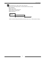
⑦Operation setup when file creating
At “Operation setup when file creating”, it set to send mail attached a creating file when a file is
created at setting timing.
Click “Operation setup when file creating”, it displays the menu below.
①
②
③
48
Data Logger Light
Item
①
Send by attaching to mail.
②
Select destination
③
Upload by FTP
Contents
Check box to send a file attaching to mail when the file is
created.
Check boxes of name to be sent mail.
You can send mail to several destinations by checking boxes.
(Max. 16 users)
Check box and upload by FTP server.
Point
Sending mail contents is as below.
Title: File name[YYMMDDHHMMSS][Occurrence]
Body: None
Ex.) Logging file name: sekisan Time: August 1st 2010 12:00:00
-> Title is sekisan[100801120000][Occurrence].
Note
・Is you set operation when file creating, set the cycle to at least 5 minutes for sending
mail and updating cycle with FTP.
・If there are spaces with the name of attached file, some mail-sever can’t send it.
・Set different timings to send mail, upload by FTP, and create new file, if not, it may not
attach file to mail.
Retry
In case of that the logging file can’t send by mail or FTP, you can retry by the setting.
The file that it retries to send is the same logging file that is intended to send first.
Even if the logging trigger is happened at retry, it doesn’t add new data to the logging file.
Reference
<7.2.7 Mail sending setup>
<7.2.10 LAN port setup>
49
Data Logger Light
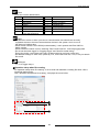
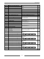
7.2.5 Logging device registration
■Logging device registration
It setup data type to be collected from Eco-POWER METER or PLC connected to Data Logger Light.
■How to check the number of registered logging device
You can check the number of registered logging device.
①
②
[Shift window]
① Click “Logging device registration” in Navigator.
② The number of registered device for each file is displayed on the right.
Note
・Max. registered number is 300 points total of 16 files.
If 300 points are registered in 1 file, no more point is registered in another file.
However, max. registered number of files, that is set available to collect DEC4W
data, is 150 points total. Max. registered number is 300 points total of 16 files.
・When registered number is over 256 points (include date and time), it can’t opened with
Excel 2003 or before version.
50
Data Logger Light
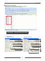
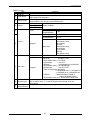
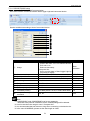
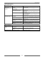
■Logging device registration
It sets each items of logging data items and logging conditions.
Click file to set and display the list on the right.
Double-click any No.’s rows to setup.
Item
File number
Contents
Max. 16 files (300 points per 1 file *1)
*1 150 points for files that is set available to collect DEC4W data.
Ex.) MEWTOCOL
[Relay] is the target
[Register] is the target
①
①
②
③
②
③
④
④
⑤
⑥
⑧
⑨
⑦
⑭
⑪
⑫
⑬
⑭
51
Data Logger Light
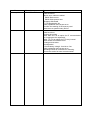
[MEWTOCOL]
Item
① Register No.
② Register name
③ Communication I/F
④ Data type
⑤
Device *2
Relay
⑥
Logging contents
⑦
Count conditions *3
⑧
Device *2
Data style
Register
⑩
Collecting and logging data
⑨
-
⑪
Logging contents
⑫
Digit *4
Convert
when creating csv
⑬
⑭
Unit
Contents
1 to 300 (not available to collect DEC4W data)
1 to 150 (available to collect DEC4W data)
Input register name.
Max. 32 letters *1
Main unit / COM1(RS232C) / COM2(RS485)
Unit No. 1:1 / 1:N (1 to 99)
Relay / Register
・Select from X,Y,R,L,T,C
・Relay number(Decimal)
Inst.value(ON/OFF), Accumulated ON time,
Total switching times
OFF→ON, ON→OFF, ON⇔OFF
・Select from WX, WY, WR, WL, DT, LD, SV, EV, FL.
・Register number(Decimal)
・DEC1W
・DEC1W(No code)
・HEX4 digits
・DEC2W
・DEC2W(No code)
・HEX8 digits
・Real number
・DEC4W
・DEC4W(No code)
・Inst.value
・Ave.value
・Min.value
・Max.value
・Diff.value (Digit can be input only for differential value.)
0 to 19 *5 (only for differential value)
It multiplies the coefficient when creating csv.
Input range: -99999.999 to 99999.999
(Number of significant figures: 6 digits)
Max. 4 letters
Note
*1 It can’t use the below letters.
letter
name
,
comma
“
Double quotation
*2 Input data register number to collect.
Ex.) When it is “Integrated electric power”, input “Register: DT100”.
Refer to the manual of each connecting device for data register number.
*3 It can be selected only when “Total switching times” is selected at “Logging contents”.
*4 It can be input when “Diff value” is selected at “Logging contents”.
It corrects data when it is over the max. digit by inputting digit number, (Ex. When setting 3
digits, the max. value is 999.) (Refer to 7.2.12)
Input the max digit number for logging items.
*5 It can be set ‘10 to 19’ only when ‘Collect DEC4W data’ is set to available. Ex.) MODBUS
52
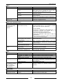
Data Logger Light
Ex.) MODBUS
[Coil] is the target
[Register] is the target
①
①
②
③
②
③
④
④
⑤
⑥
⑧
⑨
⑩
⑦
⑪
⑭
⑫
⑬
⑭
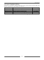
[MODBUS]
Item
① Register No.
② Register name
③ Communication I/F
④ Data type
⑤
Device *2
Relay
⑥
Logging contents
⑦
Count conditions *3
⑧
Device *2
Data style
Register
⑩
Collecting and logging data
⑨
Reading value
⑪
Logging contents
⑫
Digit *4
Convert
when creating csv
⑬
⑭
Unit
Contents
1 to 300 (not available to collect DEC4W data)
1 to 150 (available to collect DEC4W data)
Input register name.
Max. 32 letters *1
Main unit / COM1(RS232C) / COM2(RS485)
Unit No. 1:1 / 1:N (1 to 99)
Relay / Register
・Select from Coil, Input
・Relay number(Hex)
Inst.value(ON/OFF), Accumulated ON time,
Total switching times
OFF→ON, ON→OFF, ON⇔OFF
・Select from Holding register, Input register
・Register number(Hex)
・DEC1W
・DEC1W(No code)
・HEX4 digits
・DEC2W
・DEC2W(No code)
・HEX8 digits
・Real number
・DEC4W
・DEC4W(No code)
Select from Low Byte - High Byte, High byte - Low Byte
*6
・Inst.value
・Ave.value
・Min.value
・Max.value
・Diff.value (Digit can be input only for differential value.)
0 to 19 *5 (only for differential value)
It multiplies the coefficient when creating csv.
Input range: -9999.999 to 9999.999
Max. 4 letters
53
Data Logger Light
Note
*1 It can’t use the below letters.
letter
name
¥
Yen
/
Slash
Backslash
\
:
Colon
;
Semi-colon
.
dot
letter
*
?
“
<
>
|
Name
Asterisk
Question mark
Double quotation
Inequality sign
Inequality sign
pipe
*2 Input data register number to collect.
Ex.) When it is "Integrated electric power", input "Holding register: 0064".
Refer to the manual of each connecting device for data register number.
*3 It can be selected only when “Total switching times” is selected at “Logging contents”.
*4 It can be input when “Diff value” is selected at “Logging contents”.
It corrects data when it is over the max. digit by inputting digit number, (Ex. When setting
3 digits, the max. value is 999.) (Refer to 7.2.12)
Input the max digit number for logging items.
*5 It can be set ‘10 to 19’ only when ‘Collect DEC4W data’ is set to available.
*6 "Data style" can be selected when "DEC2W", "DEC2W(No code)", "HEX8 digits",
"Real number", "DEC4W" or "DEC42W(No code)" is set.
Note
・It shifts register No without closing window by using up and down button of Register No.
It shifts to another No. without any registration if “Register” is not clicked before using up
and down button.
54
Data Logger Light
・It can copy & paste the setting items.
[Procedure] Ex.) Copy items of No.1 to No.5.
1) Select row and right-click the row, it displays menu.
2) Select “Copy” from the menu.
3) Right-click row of No. to copy, it displays menu.
Select “Paste”.
4) So far copy is finished. Change the register name and unit No. and so on if necessary.
55
Data Logger Light
7.2.6 Data setups
It can rewrite the appointed relay status and register by setup trigger.
For example, it is used for initializing an appointed register when meeting some conditions.
Double-click row of No. to set from the list.
Registered data are shown in the list on the right.
Point
You can setup in RS232C/RS485 setup window. Select ‘Data setup’ for usage.
(Refer to <7.2.11 RS232C/RS485 setup>)
Ex.) MEWTOCOL
[Relay] is the target
[Register] is the target
①
②
③
①
②
③
④
⑤
④
⑥
⑦
⑧
⑦
⑧
⑨
⑨
56
Data Logger Light
[MEWTOCOL]
Item
① Data No.
②
Data Name
③
Setup trigger
④
Target
⑤
Device
⑥
⑦
Set value
⑧
Reset trigger
⑨
Save log in
system history
Contents
Display the selected registration No. (Max. 128 types)
Input data name.
Input range: Max.32 letters
Select trigger number to be set at trigger setup.
It setup data by the timing to be set at this point.
Main unit
COM1(RS232C) Relay, Register
COM2(RS485)
Main unit
Y,R
Relay
COM1(RS232C)
Y,R,L
COM2(RS485)
Main unit
WY, WR, DT
COM1(RS232C) WX, WY, WR, WL, DT, LD, SV,
COM2(RS485)
EV, FL
DEC1W
DEC1W(No code)
HEX4 digits
Register
DEC2W
DEC2W(No code)
Data style
HEX8 digits
Real number
DEC4W
DEC4W(No code)
Relay status
ON, OFF
Input value to be set to register.
DEC1W
: -32768 to 32767
DEC1W(No code) : 0 to 65535
HEX4 digits
: 0 to FFFF
DEC2W
: -2147483648 to 2147483647
DEC2W(No code) : 0 to 4294967295
Register
HEX8 digits
: 0 to FFFFFFFF
Real number(single precision)
:-3.4028235E+35 to -1.401298E-45
: 1.401298E-45 to 3.4028235E+38
DEC4W
: -9223372036854775808 to
9223372036854775807
DEC4W(No code): 0 to 18446744073709551615
Select trigger No to be set at trigger setup.
OFF is set for relay, “0” is set for register at the timing to be set
at this point.
Check box to save log of data setting.
57
Data Logger Light
Ex.) MODBUS
[Relay] is the target
[Register] is the target
①
②
③
①
②
③
④
⑤
④
⑥
⑦
⑧
⑦
⑧
⑨
⑨
[MODBUS]
①
Item
Data No.
②
Data Name
③
Setup trigger
④
Target
⑤
Device
⑥
Contents
Display the selected registration No. (Max. 128 types)
Input data name.
Input range: Max.32 letters
Select trigger number to be set at trigger setup.
It setup data by the timing to be set at this point.
Main unit
COM1(RS232C) Relay, Register
COM2(RS485)
Main unit
Y,R
Relay
COM1(RS232C)
Coil
COM2(RS485)
Main unit
WY, WR, DT
COM1(RS232C)
Holding register
COM2(RS485)
DEC1W
DEC1W(No code)
HEX4 digits
Register
DEC2W
DEC2W(No code)
Data style
HEX8 digits
Real number
DEC4W
DEC4W(No code)
58
Data Logger Light
Relay status
Set value
⑦
Writing order
⑧
Reset trigger
⑨
Save log in
system history
ON, OFF
Input value to be set to register.
DEC1W
: -32768 to 32767
DEC1W(No code) : 0 to 65535
HEX4 digits
: 0 to FFFF
DEC2W
: -2147483648 to 2147483647
DEC2W(No code) : 0 to 4294967295
Register
HEX8 digits
: 0 to FFFFFFFF
Real number(single precision)
:-3.4028235E+38 to -1.401298E-45
: 1.401298E-45 to 3.4028235E+38
DEC4W
: -9223372036854775808 to
9223372036854775807
DEC4W(No code): 0 to 18446744073709551615
Low Byte - High Byte, High byte - Low Byte
Selectable when the register is set to "DEC2W", "DEC2W(No code)",
"HEX8 digits", "Real number","DEC2W" or "DEC2W(No code)".
Select trigger No to be set at trigger setup.
OFF is set for relay, "0" is set for register at the timing to be set at this
point.
Check box to save log of data setting.
59
Data Logger Light
7.2.7 Mail sending setup
It sends mail to the specified address by setting trigger.
For example, if it set to detect abnormal value at trigger setup, it will send mail when detecting
abnormal value. It is used for receiving the information of occur some errors.
In addition, it sends a file attached to mail at sending mail.
Double-click row of No. to set from the list.
①
②
③
④
⑤
⑥
⑦
60
Data Logger Light
Item
Contents
Data No.
Display the selected registration No. (Max. 128 types)
①
Select trigger number to be set at trigger setup.
Trans. trigger
②
It sends mail by the timing to be set at this point.
Input title of sending mail.
Title
③
Input range: Max. 16 letters
Input body of sending mail.
Body
④
Input range: Max. 254 letters
Select destination address to send mail.
Click box to select.
Select destination
⑤
Mail addresses are registered
at “Configuration->Mail send registration”
Logging file is attached.
Check box to send mail with attaching a file.
⑥
Attached file number
When attaching file to mail, set the file number to attach.
⑦
After registration, it displays in the list on the right.
Note
・In order to send mail, it is necessary to setup items for destination and mail beforehand.
Refer to LAN port setup (7.2.10)
・To use "Fixed Cycle" for the trigger of mail transmission, set the cycle to at least 5
minutes.
・Note that when attaching file to mail, attached file might not be sent depending on mail
server if a space is included in the file name.
・Set different timings to send mail, upload by FTP, and create new file, if not, it may not
attach file to mail.
61
Data Logger Light
7.2.8 Transmit to Data Logger Light and Read out from Data Logger Light (Access to Main unit)
It transmits the setup data to Data Logger Light.
And it reads out from the setup data from Data Logger Light to Configurator DL.
Item
Read out from
Data Logger Light
Transmit to Data
Logger Light
Contents
Read out the setup data from Data Logger Light to Configurator DL.
Write the setup data to Data Logger Light.
■Access to Data Logger Light
When communicating to Data Logger Light (transfer or read out), select communication I/F.
You can transmit via USB port or LAN port.
After selecting, click “Execute”.
In case of [USB port]
Item
Used port No.
Contents
Select connected port of USB.
After PC recognizes USB, COM port can be selected.
If COM port is not displayed, confirm the connection status.
Point
・You can check COM port by
“Control panel → System → Property → Device manager”
Note
・In case of using USB port, install USB driver attached to “Configurator DL”.
(Refer to 6.1.3)
62
Data Logger Light
In case of [LAN port]
①
②
③
②[Specify IP address and communicate.]
①
②
③
Item
Computer IP address
Specify IP address and
communicate.
Searching Data Logger
Light and communicate.
③[Searching Data Logger Light and communicate.]
Contents
It displays IP address of computer.
Input IP address of connected Data Logger Light.
It searches Data Logger Light on the network.
After searching (double-click), select the unit to communicate.
Note
・Operation mode should be set to “STOP” during transmitting data.
・After transmitting data, it will restart.
Therefore it will take time to recognize USB, LAN connectors.
・If Data Logger Light is in the different network group from PC, it cannot communicate.
It is necessary to change IP address of Data Logger Light or PC.
Confirm your system administrator about using IP address.
・Input the same port No. set at “Configuration -> ort Number” for MEWTOCOL.
(Refer to 7.2.14)
Point
At the below menu, you should select communication I/F.
・When transmitting data at Easy-setup and Wizard
・Read out from Data Logger Light
・Transmit to Data Logger Light
・Mode change
・Setup initialize
・Update firmware
・Status view
・Current value monitor
63
Data Logger Light
7.2.9 Password setup
It sets password that is used when transmitting data or reading out data for Data Logger Light.
Password setting prevents from unconsidered changing setups.
①
②
③
④
Item
①
Password setup
②
Current password
③
Setup password
④
Password (re-enter)
Contents
・It registers password
・Delete password
Input the password that is set at the moment.
Input range: Max. 8 letters
Input new password
Input range: Max. 8 letters
Input new password again to confirm.
Input range: Max. 8 letters
Point
・Password setup in this point is different from the password to access FTP server.
This password is used when it updates setup data.
・After password is set, it will request the password at the time when the menus below are
executed.
Read out from Data Logger Light
Transmit to Data Logger Light
Update firmware
・When you forget the password, execute the one of these and it delete the password.
In this case, setup data are initialized.
Take care for the operation and handling password.
①Click “clear” button.
②Initialize the setups and transmit to Data Logger Light
③Initialize Data Logger Light
Note
Password setting is designed to avoid setups being accidentally changed. If the
password is forgotten, however, it will be impossible to change the setup data
even if you want to. When specifying password, note it in the safe place in case
that it is forgotten at some point.
It is impossible to crack the password by our company.
64
Data Logger Light
7.2.10 LAN port setup
It sets each setting of LAN port. It is necessary to set Data Logger Light on the network.
Set IP address and each setting for mail sending.
Point
Confirm to your network system administrator about each setting.
■IP address
It set IP address of Data Logger Light
①
②
③
④
①
Item
Obtain an IP address automatically
②
Use the following IP address
③
Obtain DNS server address automatically
④
Use the following DNS server addresses
Contents
It obtains an IP address automatically.
Input any IP address, subnet mask and
default gateway.
It obtains DNS server address automatically.
Input any preferred DNS server and
alternate DNS server.
[Initial]
Item
Contents
IP address
Subnet mask
Default gateway
192.168.1.5
255.255.255.0
192.168.1.1
Point
When you check the box of ‘Obtain an IP address automatically’, it will obtain IP address
by sending request to DHCP server at starting the unit (turn on power, transmit settings,
restart after updating firmware). In case of failure of the obtain, it will retry for 30 minutes
every α seconds, (α: 0 to 60 at random, set at every time). After the failure of retry, it
will set the standard address (192.168.1.5) and it will be error.
65
Data Logger Light
What is “DNS server”?
Domain Name System (DNS) is a service that obtains IP address from a computer name.
The computer provides this service is called DNS server. IP address can be obtained by
inquiring to server.
It is necessary to appoint by name for the below functions.
・Sending mail (SMTP server or POP server)
・Auto time setting (SNTP server)
66
Data Logger Light
■Mail sending
It setup items to send mail.
①
②
③
④
⑤
⑥
⑦
①
②
③
④
⑤
⑥
⑦
Item
Mail address of Data Logger Light
Contents
Set mail address of Data Logger Light.
Input IP address or name of SMTP
SMTP server
server.
It doesn’t authenticate when sending
Not need to authenticate
mail.
POP before SMTP(Standard) Account: Max. 48 letters
Password: Max. 16 letters
Authentication
POP before SMTP(APOP)
POP server: Max. 48 letters
Account: Max. 48 letters
SMTP AUTH
Password: Max. 16 letters
Set time-out time.
Connected time-out
Select from 30,60,90,120,300 sec.
Set retry interval to send mail.
Select from
Retry interval
0,1,2,3,4,5,10,15,30,60 min.
Set retry frequency to send mail.
Retry frequency
Select from the range of 0 to 10 times.
The order of data row of attached file
Ascending, Descending
Note
*1 SMTP over SSL/TLS is not supported.
Point
Confirm to your network system administrator about each setting.
What is “POP before SMTP”?
It is a method of authorization to use SMTP server by accessing beforehand to an appointed
POP3 server (protocol for receiving mail from server that saves e-mail.) before sending.
The part of password in not coded with “Standard” and the part of password is coded with
“APOP”.
67
Data Logger Light
What is “SMTP AUTH”?
It gives an authorization to send mail only when it authorizes user account and password
with user at sending mail (connecting to SMTP server).
However, it is necessary that both server and client are support it.
About “The order of data row of attached file”
It can sort data in file to be attached to mail.
Ascending
Descending
Note
・Only attached file is available.
・Sequence is changed in attached file, but logging file and CURRENT file in SD memory
card or internal memory is not changed (ascending).
68
Data Logger Light
■FTP
It sets items for FTP.
FTP is network protocol in order to use for transmitting file between a server and a client.
It is necessary to upload files from Data Logger Light to server or download file data from Data
Logger Light.
①
②
③
④
⑤
⑥
⑦
⑧
⑨
⑩
⑫
⑪
Item
①
FTP server name
②
FTP server address
User name
③
Anonymous
④
FTP client setup
Password
⑤
Access folder
⑥
PASV mode
Connected
time-out
⑦
⑧
Retry interval
⑨
Retry frequency
⑩
User name
FTP server setup
⑪
Password
⑫
Allow anonymous
69
Contents
Input FTP server name.
Input range: Max. 32 letters of
half size alphabetic letter,_.-@
Input FTP server address.
Input range: Max. 64 letters of
half size alphabetic letter, _.-@<>!#$%&()=
Input user name for FTP server
Input range: Max. 32 letters
Check when anonymous is used.
Setup password for FTP server
Input range: Max. 32 letters of
half size alphabetic letter,_.-@
Setup access folder. *1
Input range: Max. 128 letters of
half size alphabetic letter
Check box when PASV is used.
Setup time for time-out.
Select from 5,10,15,30,60,90,120,300 sec.
Setup retry interval.
Select from 0,1,2,3,4,5,10,15,30,60 min.
Select retry frequency for sending mail.
Select from 0 to 10 times.
Input user name
Input range: Max. 32 letters of
half size alphabetic letter,_.-@
<initial> admin
Setup password.
Input range: Max. 32 letters of
half size alphabetic letter,_.-@
<initial> dlu
Check box when anonymous is used.
Data Logger Light
Note
*1 Data Logger Light doesn’t make folder for FTP server. It is necessary to make folder
to access.
Point
Confirm to your network system administrator about each setting.
What is “anonymous”?
If you input “anonymous” as user name and your mail address as password, you can use
FTP service without an account.
There is a custom of input one’s mail address as a password to login.
It is used for open data to unspecified number of public widely.
What is “PASV”?
It is one of the communication modes to use with FTP.
In normal mode, server requests connection for data transmission to client after connecting
client to server and it communicates using this connection.
However, when the client is behind a firewall, it is unable to accept incoming request directly
from outside. When using PASV mode, client connect to server first and the client requests
connection again. Herewith the request is always from client to server. Therefore it there is
a firewall, it is possible to transmit files.
Point
Password in this window is the password to access Data Logger Light with FTP or to access
FTP server.
It is different from the password to update setup data or firmware.
FTP Client function
Created files can be transmitted to FTP server from Data Logger Light when logging file or
system history file or trigger history file is created.
Ex.)
FTP server
Data Logger Light
*Confirm your server manager about each settings.
Reference
<7.2.4 Logging file setup>
<8.1.2 System history file>
<8.1.3 Trigger history file>
70
Data Logger Light
‘Connected time-out’ ‘Retry interval’ ‘Retry frequency’
In case of using FTP client function, it can retry with the above settings.
[Retry conditions]
・E0071: Log in error
・E0072: PASV mode change error
・E0073: Directory change error
・E0075: Send error
Error/
Time-out
Retry interval
Resend
*When it sent the setting retry frequency and the result is error, it will record error history.
71
Data Logger Light
7.2.11 RS232C/RS485 setup
It sets items for RS232C/RS485 communication.
Set communication conditions between Data Logger Light and connected device.
Set the conditions according to that of connected device.
①② ③④ ⑤⑥ ⑦⑧
⑨ ⑩
Item
①
Usage
②
③
④
⑤
⑥
⑦
⑧
Communication protocol
Unit No. *2
Baud Rate
Data length
Parity
Stop bit
Timeout (sec) *3
Sending cycle of collecting
command (x10ms)
Retry of collecting
command
⑨
⑩
Contents
・Data collection:
Collect data from our Eco-POWER METER,
PLC and so on.
Select at data setup.
・Computer link:
Use to monitor data in Data Logger Light by
connecting a display.
MEWTOCOL, MODBUS *1
Set its unit No. Selectable range: 1 to 99
4800,9600,19200,38400,57600,115200bps
7-bit, 8-bit
Odd, Even, None
1-bit, 2-bit
1 to 60
Initial
Data
collection
MEWTOCOL
-
19200bps
8-bit
Odd
1-bit
5
0 to 9999 (When 0 is set, it means best effort.)
10
Yes, No
Yes
Note
*1 COM1(RS232C) and COM2(RS485) can be set separately.
Note that if the protocol is switched, all the related settings will be deleted.
*2 It can be set when the usage is set to “Computer link”.
*3 It is recommended that set timeout to long when connecting a wireless device.
*4 In the case of MODBUS, please set the data length to 8 bits.
72
Data Logger Light
What is “best effort”?
At network connection, when several person connect at the same time, the execute speed
is changed. It communicates with best communication cycle among these.
About “transmission interval of collecting command”
DLL is always sampling data during RUN mode regardless the setting logging cycle.
Transmission interval of collecting command
[DLL]
Request command
Request command
Response
[Outer device]
When it is receiving the response of it is timed out even if it passes “transmission interval
of collecting command”, it send the next request command after 5ms in the shortest.
Transmission interval of
collecting command
[DLL]
5ms in the shortest
Request command
[Outer device]
Request command
Response
73
Data Logger Light
7.2.12 Details of data to be logged
[Relay]
Logging ways are selected from the below.
1) Inst.value 2) Accumulated ON time 3) Total switching times
○
4) ON status/ OFF status
: Inst.value
: Accumulated ON time
Logging cycle 1
Logging cycle 2
①
Logging cycle 3
②
③
1) Inst.value: ON/OFF status of relays is recorded for every logging cycle.
Data recorded in file is “1” in on-state and “0” in off-state.
2) Accumulated ON time: Time when relay turns on is recorded for every logging cycle.
Ex.)
Time
ON time of logging cycle 1 : 3 seconds
ON time of logging cycle 2 : 6 seconds
ON time of logging cycle 3 : 2 seconds
Data
Data recorded at the point of ① : 3
Data recorded at the point of ② : 9
Data recorded at the point of ③ : 11
3) Total switching times: Number of switching times of relay is recorded for every logging cycle.
Counting condition can be selected from the below.
・Leading edge (OFF→ON)
・Trailing edge (ON→OFF)
・Both edge differential (ON⇔OFF)
Ex.) In case of that the counting condition is set to “Leading edge (OFF→ON)”
Times
Data
Switching times of logging cycle 1 : 2 times
Data recorded at the point of ① : 2
Switching times of logging cycle 2 : 0 time
Data recorded at the point of ② : 2
Switching times of logging cycle 3 : 1 time
Data recorded at the point of ③ : 3
Note
Total switching times is cleared at the timing below.
・Change operation mode RUN to STOP
・Power ON to OFF
74
Data Logger Light
4) ON status/ OFF status: Detect status when it keeps ON status or OFF status more than 200ms.
It is used effectively by combination of other conditions.
Ex.) Fixed Cycle: 1 hour + ON status
It starts logging when it passes 100ms from 1:00, 3:00.
It logs data of 1 hour from 1:00 and 3:00 and it does not log data of 1 hour from 2:00.
It can be used that it logs a fixed period.
1:00
2:00
3:00
75
Data Logger Light
[Register]
Logging ways are selected from the below.
1) Inst.value 2) Ave.value 3) Min.value 4) Max.value 5) Diff.value
○:Inst.value
:Ave.value ×:Min.value △:Max.value
△○
△
○
△
○
×
○
×
×
Logging cycle 1
Logging cycle 2
Logging cycle 3
1) Inst.value: Latest value for every logging cycle are recorded.
2) Ave.value: Average values are calculated from sampling data in logging cycles and recorded for
every logging cycle.
3) Min.value: Minimum values are calculated from all sampling data in logging cycles and recorded
for every logging cycle.
4 ) Max.value: Maximum values are calculated from all sampling data in logging cycles and
recorded for every logging cycle.
Note
Regardless of a specified logging cycle, Data Logger Light checks the status to send
commands every 10ms. If it can send command, it sends command after completing waiting
for receiving and waiting for sending 5 ms.
Therefore, the values are not always calculated by same number of data according to
the communication conditions.
○
○
○
○
①
②
③
④
5) Diff.value : Values subtract previous values are recorded for every logging cycle.
It can be used for application that collect an integrated electrical power (DT100) and
record using electrical power at a fixed time interval.
Ex.)
No.
①
②
③
④
Inst.value
100
150
180
190
Diff. value
(Value that subtract the previous value from 100)
50 (②-①)
30 (③-②)
10 (④-③)
76
Data Logger Light
Note
When it is used with difference value, specify a digit number.
Ex.)
When digit number is specified “3”, max value of the logging device is “999” for
Data Logger Light.
Therefore, when value at ① is “100” and value at ② is “50”, Data Logger Light
considers value at ② as “1050” and the result of ② minus ① is “950”.
If digit number is not specified, the result of ② minus ① is “-50”. But it is
“0xFFFFFFCE=4294967246” for DEC2W(No code of data type and it is “0xFFCE=65486”
for DEC2W(No code)”.
For data type ‘DEC4W’ or ‘DEC4W(No code)’, when the digit number of difference value
is 15 or more, it doesn’t calculate correctly.
77
Data Logger Light
7.2.13 Trigger setup
It is necessary to set timing to execute in order to log data, update file, setup data or send mail by
Data Logger Light.
The timing is called “trigger”.
There are following types for the trigger.
Trigger type
Contents
・Occur every hour on the hour second, minute, hour
Fixed Cycle
・Start counting soon after RUN (Specified any time.)
・Per Minute (Appoint the second for every minute.)
・Per Hour (Appoint the minute and second for every hour.)
・Every week
(Appoint the time for every week (possible to appoint day))
Appointed time
・Every day (Appoint the time for every day.)
・Every month (Appoint the date and time for every month.)
・Every year (Appoint the date and time for every year.)
・Appointed time (Appoint date and time.)
・Leading edge (OFF to ON)
・Trailing edge(ON to OFF)
・Both edge differential
Relay
・Accumulated ON time
・Total switching times
・ON status
・OFF status
・= (equal to condition value)
・> (more than condition value)
Register
・< (less than condition value)
・≠ (different to condition value)
Combination
・Specify with “AND” or “OR” for 2 trigger.
78
Data Logger Light
[How to set]
1) Double-click row of No. to setup.
・Max. 128 types of trigger can be set.
2) Input trigger name and select trigger type.
Set items for selected trigger type.
After completing all input, click “OK”.
Item
Trigger Name
Record to trigger history file when trigger is
happened.
Contents
Input name of trigger.
Input range: Max. 32 letters
Check box to record to trigger history file when
it occurs trigger.
Note
“Record to trigger history file when trigger is happened.” is available only when “Relay”,
“Register” or “Combination” is selected.
79
Data Logger Light
■Fixed Cycle
Select “Fixed Cycle” at Trigger Type. It occurs trigger every cycle.
Trigger happening conditions
Occur every hour on the hour
Start counting soon after RUN
Contents
It occurs trigger based on every hour sharp.
Ex.1) When set to 5 seconds.
Trigger occurrence time:
0, 5, 10,・・・・50, 55 seconds for every minute
Ex.2) When set to 15 minutes.
Trigger occurrence time: 0, 15, 30, 45 minute for every hour
It starts counting at changing to RUN mode.
Ex.1) When set to 5 seconds
and change to RUN mode at 12:15:20
Trigger occurrence time:12:15:25, 12:15:30, 12:15:35・・・
Ex.2) When set to 15 minutes
and change to RUN mode at 12:10:00
Trigger occurrence time:12:25:00, 12:40:00・・・
■Appointed time
Select “Appointed time” at Trigger Type. It occurs trigger at the appointed time.
The following appointments are available.
Item
Contents
Per Minute
Appoint the second for every minute.
Per Hour
Appoint the minute and second for every hour.
Every week
Appoint the time for every day.
Every day
Appoint the time for every day.
Every month
Appoint the date and time for every month.
Every year
Appoint the date and time for every year.
Appointed time
Appoint date and time.
80
Data Logger Light
■Relay
Select “Relay” at Trigger Type. It occurs trigger according to the status of relay.
[MEWTOCOL]
[MODBUS]
It is available to set as below.
Target
Main unit
COM1(RS232C)
MEWTOCOL
COM2(RS485)
COM1(RS232C)
MODBUS
COM2(RS485)
Condition
Leading edge (OFF to ON)
Trailing edge(ON to OFF)
Both edge differential
Accumulated ON time
(Specify second)
Total switching times
(Specify time)
ON status *1
OFF status *1
Device
R
X,Y,R,L,T,C
Coil
Contents
It occurs trigger when it detects the change of OFF to ON.
It occurs trigger when it detects the change of ON to OFF.
It occurs trigger when it detects the change of OFF to ON or
ON to OFF.
It occurs triggers when total time of detection ON status is
over the specified time.
It occurs trigger when total switching times of OFF to ON is
over the specified time.
It occurs trigger with ON status.
It occurs trigger with OFF status
Note
*1 It judges for trigger every about 100ms.
Target
Record to trigger history file
when trigger is occurs.
Contents
It creates trigger history file and saves in trigger history file
when it occurs trigger.
81
Data Logger Light
■Register
Select “Register” at Trigger Type.
When it meets the condition after comparing setting register value and condition value,
it occurs trigger.
[MEWTOCOL]
[MODBUS]
It is available to set as below.
Target
Main unit
COM1(RS232C)
MEWTOCOL
COM2(RS485)
Device
・DEC1W
・DEC1W(No code)
・HEX4 digits
・DEC2W
・DEC2W(No code)
・HEX8 digits
・DEC4W
・DEC4W(No code)
WR,DT
WX,WY,WR,
WL,DT,LD,
SV,EV,FL
COM1(RS232C)
MODBUS
Holding register
COM2(RS485)
Condition
Make trigger only when
meeting the conditions.
Keep trigger during when
meeting the conditions.
Contents
It occurs trigger when it meets conditions.
It occurs and keeps trigger during it meets conditions.
Note
Set with real value not conversion value for the conditions.
■Combination
Select “Combination” at Trigger Type.
Set to combine 2 type of trigger and it occurs trigger when it meets both conditions.
82
Data Logger Light
7.2.14 Configuration
You can set the following items for configuration.
1) Logging file setup
2) Operation when occurring error
3) Port number
4) Clock
5) Mail send registration
6) Language
: Set conditions to create logging file.
: Set operations when error is occurred.
: Set port number of each protocol.
: Set time of Data Logger Light.
: Register user to send mail.
: Change displayed language.
■Logging file setup
①
②
③
⑤
④
⑥
⑦
⑧
⑨
⑩
⑪
⑫
⑬
[Initial]
①
②
③
④
⑤
⑥
⑦
⑧
⑨
⑩
⑪
⑫
⑬
Contents
Make file with logging data in SRAM when RUN to
STOP.(_MOD)
Make file with logging data in SRAM when power on.(_POW)
Timing of creating file from logging data in SRAM
Use most recent data for the accumulation data
Reply by the real number form.
Timing in which logging file is generated is moved.
When there are vacant rows with logging device registration.
The number below a decimal point
Information to record at header
Record date and time
Record style for the hour of 0:00
Set file name
Make the destination folder name of logging file [CF].
83
Initial
Available
Available
Auto
Available
Not available
No
Record by left aligned
2
Available all
Record separately.
Record "0:00"
Available all
Not available
Data Logger Light
①Make file with logging data in SRAM when RUN to STOP.(_MOD)
“_MOD” file is created even if the number of logging data is not reached to the appointed
record number when mode switch is changed RUN to STOP.
Ex.) sekisan(100801_001500_MOD).csv
Note
There is the case that data lack when I exclude a check. But frequently mode reshuffling
Please be careful when I perform it because there is the case more than the save
file numbers.
②Make file with logging data in SRAM when power on.(_POW)
CURRENT file is renamed to “_POW” when Data Logger Light turns on and there is a
CURRENT file.
Ex.) sekisan(100801_001500_POW).csv
Note
There is the case that data lack when I exclude a check. But frequently mode reshuffling
Please be careful when I perform it because there is the case more than the save
file numbers.
③Timing of creating file from logging data in SRAM
Auto
: When 64 records are logged in SRAM, it creates file.
By 1-record
:When 1 record is logged, it creates file.
④Use most recent data for the accumulation data
DLL is always sampling data regardless the setting logging cycle.
In this setting, you select that the collecting data is logged or not logged when it occurs
the logging trigger. It is useful when communication error is happened when it occurs
the logging trigger.
Ex)
Logging cycle 2
Logging cycle 3
③
Logging cycle 1
B
②
Communication error
①
A
:Sampling
Set to “OFF”
At ①:Data is not collected due to communication error.
At ②:Data is not collected due to communication error.
At ③:Log the data ”B”.
Set to “ON”
At ①:Log the most recent data “A” due to communication error.
At ②:Data is not collected due to communication error during logging cycle 2.
At ③:Log the most recent data “B”.
84
Data Logger Light
⑤Reply by the real number form.
It replies by the real number form when reading data from upper communication of Data
Logger Light. Use this when conversion value is displayed on the current value monitor and
conversion value is acquired from the internal register.
⑥Timing in which logging file is generated is moved.
It creates file by delaying timing.
Ex.) Update file trigger: 10 records
No: It creates “CURRENT file” up to 9th record and creates logging file at 10th record.
Yes: It creates “CURRENT file” up to 10th records, logging file with 1st to 10th record at
11th record, “CURRENT file” with 1 record.
⑦When there are vacant rows with logging device registration.
・Record by left aligned
: Logging data is recorded by left aligned.
・Record without cutting the row
: It records without cutting the row.
In case of “Record by left aligned”
In case of “Record without cutting the row”
Note
In case of using our “KW Watcher”, we recommend “Record by left aligned”.
⑧The number below a decimal point
When data with real number style is recorded in logging file, specify digit number below a
decimal point.
Specified range: 0 to 6
85
Data Logger Light
⑨Information to record at header
Select information added to header of the logging file.
[Ex.]
Header
Item
1
Reg. No.
Integrated
Register name
COM1
Communication I/F
DT100
Register device
MOMENT
Logging contents
FLT
Data style
kWh
Unit
Header
Point
Indications of logging contents and data style
Letters to record in file
Logging contents
STATUS
Inst.value (Relay)
TOTAL ON TIME
Accumulated ON time
TOTAL SW TIMES
Total switching times
MOMENT
Inst.value
AVERAGE
Ave.value
MINIMUM
Min.value
MAXIMUM
Max.value
DIFFERENCE
Diff.value
Letters to record in file
S16
US16
HEX4
S32
US32
HEX8
FLT
S64
US64
Data style
DEC1W
DEC1W(No code)
HEX4 digits
DEC2W
DEC2W(No code)
HEX8 digits
Real number
DEC4W
DEC4W(No code)
Note
・In case of converting the logging device, data style is displayed as “US16→FLT”
(style before conversion→style after conversion)
⑩Record date and time
・Record separately. : Record date and time separately.
[Ex.]
2010/8/1
15:30:00
・Record in the same cell : Record date and time in the same cell.
[Ex.]
2010/8/1 15:30:00
Note
In case of using our “KW Watcher”, select “Record separately”.
86
Data Logger Light
⑪Record style for the hour of 0:00
・Record "0:00"
: 1 hour after “1st 23:00” is “2nd 0:00”.
・Record "24:00"
: 1 hour after “1st 23:00” is “1st 24:00”.
Note
In case of using our "KW Watcher", select "Record "0.00"".
⑫Set file name
Select items to name a logging file.
It doesn’t use to name the items without check box.
[Ex.]
File name: “TEST”
The date of the first data: August 1 2010 09:30:00
Folder construction [SD or RAM]/TEST/Log/TEST(100801_09300_SET).csv
・Create folder
: “/Log”
・Add "( )"
: “( )”
・Add time data
: “_09300”
・Add file creation conditions: “_SET”
・2 digits of year
: ”100801”
2 digits: 100801
4 digits: 20100801
Note
・In case of using our “KW Watcher”, check all boxes.
If even one box is unchecked, it can’t download data because the path name is different.
・If “Create folder” is not checked, files will be created under directly [SD or RAM]. In this
case, only 128 files will be created.
If “Create folder” is not checked, format SD memory card with FAT32.
⑬Make the destination folder name of logging file [CF].
Check this box, destination folder name of logging file will be “CF”.
[Ex.]
CF/TEST/Log/TEST(100801_09300_SET).csv
Note
Our “KW Watcher” downloads data under CF folder.
In case of using “KW Watcher”, check this box.
It is available when the destination is set to internal memory.
87
Data Logger Light
■Operation when occurring error
①
②
③
④
[Initial]
①
②
③
Item
Permit to write in SD memory card when opening SD card
cover.
Check battery voltage
Hardware error
Send error contents by mail Data collection error
when the below errors occur.
File creation error
Time setup error
Initial
Not available
Available
Not available
Not available
Not available
Not available
①Permit to write in SD memory card when opening SD card cover.
It is possible to write SD memory card even if the cover is opened.
Use this function when the cover is missing or damaged temporary.
It is the function to avoid removing and inserting SD memory card, uncheck this box normally.
Note
When you’d like to remove SD memory card during check this box, confirm that it doesn’t
access SD memory card by SD access indicator LED. If you remove SD memory card
during access, it might damage data.
②Check battery voltage
It checks the battery voltage.
Note
When logging file is saved in the internal memory or internal calendar is used, be sure to
check this box.
88
Data Logger Light
③Send error contents by mail when the below errors occur.
When one of the selected errors as below occurs, it can send mail to the appointed mail
address.
Item
Hardware error
Data collection error (timeout/response error)
File creation error (SD access error/ Memory capacity shortage)
Time setup error (No connection to SNTP server)
④Select mail destination
Click to check box of address to send mail.
(In order to delete the mailing list, remove check by click box again.)
Reference
<7.2.7 Mail sending setup>
89
Data Logger Light
■Port number
It sets port number of each protocol.
[Initial]
Item
MEWTOCOL-TCP(COM1)
MEWTOCOL-TCP(COM2)
FTP(server)
FTP(client)
SMTP
POP3
SMTP
Port number
9094
9095
21
21
25
110
123
What is “Port number”?
IP address is identified the computer and port number is identified the service.
Port number is classified to 3 as below.
Port number
Name
Object
0 to 1023
Well known port
Popular port number
1024 to 49151
Registration port
Registered port number
49152 to 65535
Dynamic/Private port
Port number to use free
Initial value is popular port number.
In order to improve security or avoid double the port, some system configuration has other
port numbers except the initial value.
Confirm to your system administrator about port number.
Note
When port number of MEWTOCOL is changed, change port number of LAN setting
for “Transmit data” and “Read out data” to same number.
90
Data Logger Light
■Clock
It sets date and time in Data Logger Light.
Unstable data is set at initial. Be sure to set the correct date and time before use.
●DLL time data setup
Select the way to transmit.
Item
Contents
Transmit PC time data
Transmit date and time set to PC.
Transmit the below data
Transmit date and time that is set in this point.
・Update
: Transmit selected data to Data Logger Light
・View the current time data: Read out the date and time in Data Logger Light and display it.
Reference
<7.2.8 Transmit to Data Logger Light >
Note
Be sure to mount backup battery and check the battery voltage. (Refer to 7.2.14)
91
Data Logger Light
●Auto time setup
It obtains time automatically by using time server.
Check box of “Automatically synchronize with an Internet time server (SNTP)” to use.
Item
Time zone
SNTP server *1
Synchronized
Contents
Select time zone
Input SNTP server address.
When it is specified by IP address,
check box of “Specify by IP address”.
Select synchronized trigger.
Note
*1 Confirm your system administrator about SNTP server address.
What is “Time zone”?
A time zone is a region on Earth where uses same standard time, usually referred to as
the local time. By convention, the 24 main time zones on Earth compute their local time as
an offset from UTC (see also Greenwich Mean Time).
In Japan, it is +0900.
What is “SNTP server”?
It is protocol that is used for synchronizing time of computer or network device using
network.
SNTP server sends clock value for inquiring time adjustment from a client.
It is not necessary to adjust clock manually by using this function.
Note
Synchronize trigger for SNTP should be set to different timing from the logging trigger and
create new file timing trigger. If you set same timing and the clock is back as a result of
synchronize, it will occur the logging trigger and create new file trigger and record data
with same time stamp.
92
Data Logger Light
■Mail send registration
It registers users to destination of mail.
Max. 16 users are registered.
[How to set]
1) Click row of No. to register.
2) Input destination user name and mail address.
After that, click “OK”.
Item
Registered number
Name
Mail address
Contents
Max. 16 users
Max. 16 letters
Max. 48 letters
[How to delete]
In order to delete the registered users, check box of No. to delete and click “Delete”.
93
Data Logger Light
■Language
It changes to displayed language for Configurator DL.
After changing language, restart Configurator DL.
94
Data Logger Light
7.2.15 Easy-setup
Data Logger Light can be setup only by selecting logging cycle, unit No. and connecting unit.
You can setup easy for electric power monitoring.
Following items are set with “Easy-setup”.
Item
Contents
Select logging cycle of collecting data.
Logging cyc.
Select items
15 min, 30 min, 60 min
Select unit No. to connect.
Unit No.
Select range 1 to 99
Select connecting unit to Data Logger Light.
Select
Eco-POWER METER, Multi-circuit energy checker,
connecting unit
Select items
Multi-circuit energy monitor
Multi-circuit energy monitor(3P4W unit)
Note
・It is impossible to setup additionally. If you setup with this, the current setups will be
cleared.
・In this setting, the communication protocol is MEWTOCOL.
①
②
③
①Logging cyc.
Select data logging cycle from 15min., 30 min. and 60 min.
②Select connected unit
Select unit number to connect. Click and check boxes.
③Transmit this settings
Check box and click “OK”. Setup data is transmitted to Data Logger Light.
95
Data Logger Light
Note
After completing settings and click “OK”, setup data on Configurator DL are cleared.
Reference
<7.2.8 Transmit to Data Logger Light and Read out from Data Logger Light >
96
Data Logger Light
[Select connected unit]
Right click any box to select type of connected devices from Eco-POWER METER, Multi-circuit
energy checker, Multi-circuit energy monitor.
■Eco-POWER METER
Select “Eco-POWER METER” when Eco-POWER METER is connected to Data Logger Light.
The conditions below are set automatically.
[Eco-POWER METER]
Item
Contents
New file create timing
Everyday 0:0:05
Logging file name
syunji
Saved file number
60
Data type
Register
Device
DT: 100 (Integrated electric power)
Logging file 1
Data style
DEC2W(No code)
Logging contents
Inst.value
Digit
0
Conversion value
0.01
Unit
kWh
Logging file name
sabun
Saved file number
60
Data type
Register
Device
DT: 100 (Integrated electric power)
Logging file 2
Data style
DEC2W(No code)
Logging contents
Diff.value
Digit
9
Conversion value
0.01
Unit
kWh
Configuration
Make the destination folder name of logging file [CF].
97
Data Logger Light
[KW2G Eco-POWER METER]
Item
New file create timing
Logging file 1
Logging file 2
Configuration
Contents
Everyday 0:0:05
Logging file name
Saved file number
Data type
syunji
60
Register
Integrated electric power
Device
(Register No. is changed according to the
selected Base unit or the Increase unit.)
Data style
DEC2W(No code)
Logging contents
Inst.value
Digit
0
Conversion value
0.01
Unit
kWh
Logging file name
sabun
Saved file number 60
Data type
Register
Integrated electric power
Integrated electric power (Register No. is
Device
changed according to the selected Base
unit or the Increase unit.)
Data style
DEC2W(No code)
Logging contents
Diff.value
Digit
9
Conversion value
0.01
Unit
kWh
Make the destination folder name of logging file [CF].
Note
・KW2G has one station number per one main unit.
The station number for the expansion unit is same as the connected main unit.
・Check ‘Electric Power 1’ ‘Electric Power 2’ in case of measuring 1P2W. (Ex.1)
Check ‘Electric Power 1’ in case of measuring 1P3W and 3P3W. (Ex.2)
[Ex.1: 1P2W]
*Same for the expansion units.
98
[Ex.2: 1P3W, 3P3W]
Data Logger Light
■Multi-circuit energy checker
Select “Multi-circuit energy checker” when Multi-circuit energy checker is connected to Data
Logger Light.
①
①Select circuit No.
Select circuit number.
Item
Circuit number
Contents
1 to 32
The conditions below are set automatically.
Item
New file create timing Everyday 0:0:05
Logging file name
Saved file number
Data type
Logging file 1
Logging file 2
Configuration
Contents
syunji
60
Register
Integrated electric power
Device
(Register No. is changed according to
the selected circuit number.)
Data style
DEC2W(No code)
Logging contents
Inst.value
Digit
0
Conversion value
0.1
Unit
kWh
Logging file name
sabun
Saved file number
60
Data type
Register
Integrated electric power
Device
(Register No. is changed according to
the selected circuit number.)
Data style
DEC2W(No code)
Logging contents
Diff.value
Digit
6
Conversion value
0.1
Unit
kWh
Make the destination folder name of logging file [CF].
99
Data Logger Light
■Multi-circuit energy monitor
Select “Multi-circuit energy monitor” when Multi-circuit energy monitor is connected to Data
Logger Light.
①
①Select circuit No.
Select circuit number and phase and wire system.
Item
Contents
Phase and wire system
1P2W, 1P3W, 3P3W
Circuit number
1 to 16
The conditions below are set automatically.
Item
New file create timing
Everyday 0:0:05
Logging file name
Saved file number
Data type
Logging file 1
Logging file 2
Configuration
Contents
syunji
60
Register
Integrated electric power
Device
(Register No. is changed according to
the selected circuit number.)
Data style
DEC2W(No code)
Logging contents
Inst.value
Digit
0
Conversion value
0.01
Unit
kWh
Logging file name
sabun
Saved file number
60
Data type
Register
Integrated electric power
Device
(Register No. is changed according to
the selected circuit number.)
Data style
DEC2W(No code)
Logging contents
Diff.value
Digit
9
Conversion value
0.01
Unit
kWh
Make the destination folder name of logging file [CF].
100
Data Logger Light
■Multi-circuit energy monitor(3P4W unit)
Select “Multi-circuit energy monitor (3P4W unit)” when Multi-circuit energy monitor(3P4W unit) is
connected to Data Logger Light.
①
①Select circuit No.
Select circuit number.
Item
Circuit number
Contents
1 to 4
The conditions below are set automatically.
Item
New file create timing
Everyday 0:0:05
Logging file name
Saved file number
Data type
Logging file 1
Logging file 2
Configuration
Contents
syunji
60
Register
Integrated electric power
Device
(Register No. is changed according to
the selected circuit number.)
Data style
DEC2W(No code)
Logging contents
Inst.value
Digit
0
Conversion value
0.01
Unit
kWh
Logging file name
sabun
Saved file number
60
Data type
Register
Integrated electric power
Device
(Register No. is changed according to
the selected circuit number.)
Data style
DEC2W(No code)
Logging contents
Diff.value
Digit
9
Conversion value
0.01
Unit
kWh
Make the destination folder name of logging file [CF].
101
Data Logger Light
7.2.16 Wizard setup
Data Logger Light can be setup dialogically.
Items below are set with “Wizard setup”.
Step No.
Item
Contents
Name to Data Logger Light.
It displays when communication setups or searching by
①Name
“Configurator WD”.
Step 1
Set IP address of Data Logger Light.
②Address
Select saved place for logging file.
③Data saved place
Name to logging file.
①File name
Step 2
Select logging cycle to file.
②Logging cycle
Name to item in logging data.
①Logging device name
Input communication port and target unit No.
②COM port, Unit No.
Set register number to log and conditions.
Step 3
③Input logging device
Input conversion value if necessary.
④Conversion value
Input unit.
⑤Unit
Note
・It is impossible to setup additionally. If you setup with this, the current setups will be cleared.
・In this setting, the communication protocol is MEWTOCOL.
1) Setup items about Data Logger Light.
After completing setups, click “Next”.
①
②
③
Item
①
Input name
②
Set IP address
③
Select data saved place
Contents
Input name of Data Logger Light.
It is displayed when searching by “Configurator WD”.
Input range: Max. 32 letters
*1
Set IP address of Data Logger Light.
Select saved place of logging file.
・SD memory card : It saves in SD memory card
・Internal memory : It saves in the internal memory of
Data Logger Light
102
Data Logger Light
Note
When it is saved in the internal memory, be sure to use the backup battery.
2) Setup items about logging file.
After completing setups, click “Next”.
①
②
Item
①Set file name
②Set logging cycle to file
*1 It can’t use the below letters.
letter
name
¥
Yen
/
Slash
Backslash
\
:
Colon
;
Semi-colon
.
dot
Half-width space
(only the beginning)
Contents
Input name of logging file (csv).
Input range: Max. 32 letters
Select cycle to log data from 15 min., 30 min, 60 min.
letter
*
?
“
<
>
|
Name
Asterisk
Question mark
Double quotation
Inequality sign
Inequality sign
Pipe
Note
Logging file will be updated at 00:00:05 everyday.
103
Data Logger Light
3) Setup items about logging device.
In order to register several devices, click “Register continuous”.
To complete registration, click “Next”.
①
②
③
④
⑤
Item
①Input logging device name
② Set communication port and
unit No. of device to log.
③Set logging device
Contents
Input name of logging device.
Input range: Max. 16 letters
*1
Communication port COM1(RS232C) / COM2(RS485)
Unit No.
0 to 99 *2
Input and select data information of log data.
DT
Input data register number to log.
DEC1W, DEC1W(No code),
Data style
DEC2W(No code)
Logging contents
Digit
Inst.value, Diff.value
6, 9 (Selectable only when
“Diff.value” is selected.)
No, Do
-99999.999 to 99999.999
④Input conversion value when it
is converted.
Convert
⑤Input unit.
Input unit: Max. 4 letters
Conversion value
Note
*1 It can’t use the below letters.
letter
name
,
comma
“
Double quotation
Note
*2 Unit No. is selected from 1 to 99 for COM2(RS485).
104
(Number of significant figures: 6 digits)
Data Logger Light
Point
Click “Integrated electric power (Inst.value)” and the items below are input automatically to
③, ④ and ⑤.
Item
Contents
DT
100
Data style
DEC2W(No code)
③Set logging device
Logging contents
Inst.value
Convert
Do
④Input conversion value when it is
Conversion value
0.01
converted.
kWh
⑤Input unit.
4) After completing all input, it displays the setting contents.
In order to transmit data to Data Logger Light, check box of “Transmit this settings” and click
“Complete”. If not to transmit data, click “Complete” without check box.
105
Data Logger Light
7.2.17 Firmware update
It updates firmware and upgrades software in Data Logger Light.
Point
・Extension of the firmware is “ .bin”.
・You can download the latest file of the firmware from our website.
(http://www3.panasonic.biz/ac/e/index.jsp)
・Even if the firmware is updated, It keeps setting data with the setting conditions.
(Refer to 7.2.12 about logging data in SRAM.)
・Set to ‘STOP’ mode during upgrading the firmware.
・During updating firmware, do not turn off power. It might damage data or
Data Logger Light.
・It will restart when you cancel the update firmware, after updating firmware, after error
of updating firmware.
Therefore, it takes time to recognize USB/LAN connectors.
106
Data Logger Light
7.2.18 Status view
It displays the information of Data Logger Light.
Click “OK” after input required information, it displays “Status display”.
①
⑤
②
③
⑥
④
①System information
You can confirm the time, name and firmware version of Data Logger Light.
②State of operation
You can confirm the current operation status.
Click “Clear” and clear errors displayed at the moment and ERROR LED turns off.
Note
“Clear” is used only for clear error display and ERROR LED.
It cannot used to solve an error source.
Reference
<12.3 Error Code>
③Setup data
You can confirm the updated time to set to Data Logger Light.
④Network setup
You can confirm the setup conditions for network.
107
Data Logger Light
⑤Internal memory information (byte)
You can confirm the capacity of internal memory.
⑥SD memory card information (byte)
You can confirm the vacant capacity and write times of inserted SD memory card.
Point
・Write times to SD memory card is displayed.
It is a standard of write times to SD memory card.
Write times: From inserting SD memory card to removing SD memory card
Accumulated write times: Until to initialize setup data or initialize main unit or
update firmware
[Clear timing of write times and accumulated write times]
Operation
Write times
Insert or remove SD memory card
Clear
Rewrite setup data
Clear
Setup initialize
Clear
Update firmware
Clear
Accumulated write times
Not cleared
Not cleared
Clear
Clear
Note
Write times is stored in Data Logger Light, not in individual SD memory card.
Therefore, when SD memory card is replaced in using, an accumulated write times is not
match. Even if setup data is reversed the write times is not reversed.
108
Data Logger Light
7.2.19 Current value monitor
It displays the values of logging device that is registered.
Click “OK” after input required information, it displays “Current value monitor”.
Point
・It is necessary to read setup conditions of Data Logger Light in Configurator DL before
viewing the current value.
・For device in which communication error occurs, "-" is displayed in Current value.
・Display of current value monitor is updated by 1 sec cycle.
・When “Special data register” is selected, current value of the special data register can be
monitored. (Refer to 10.1.3)
109
Data Logger Light
7.2.20 Logging file list
It displays the logging file list in SD memory card or internal memory and downloads it.
Click “Connect” after input required information for connection, it displays logging file list in SD
memory card or internal memory. Double-click the folder name to move the below folder.
After checking box of file name, click “Download” to download and click “Delete” to delete.
In case of [LAN port]
In case of [USB port]
Item
IP address
User name
Password
Contents
Input IP address of Data Logger Light.
Input user name.
Input password.
Point
You can move to above folder by using backspace key.
Note
・Max. connection number is 2. It is impossible to access if connection number is 3 or
more. (Error message is depended on the using software.)
・It cut connection if there are no operation for 90 seconds during connection. When you
select the displayed folder name or file name, it will connect again. However, there is no
selecting folder or file, it will move to root directory.
110
Data Logger Light
Right-click on the window and the small window is displayed.
You can select ”Download”, ”Delete”, ”Select all” and “Delete all”.
Point
The logging file list is displayed or downloaded with FTP commands.
Also, it is processed across firewall as PASV mode is used.
111
Data Logger Light
Chapter 8 About Creating File
8.1 Creating file
Data Logger Light creates files of following type.
1. Logging file
: Create file by collecting data.
2. System history file
: It records system history.
3. Trigger history file
: It records trigger history.
Note
There is the case that a ‘dllite.sys’ file for maintenance is created in the root folder.
8.1.1 Logging file
Data collected by Data Logger Light is stored in internal SRAM (1MB for saving data) contemporarily.
When stored data in SRAM is reaches some conditions (setting record number, setting trigger etc.),
it creates file in SD memory card (or internal memory) as csv.
SRAM
SD memory card
(Internal memory)
0x00000001
0x00000101
0x01010011
0x11001011
csv file
(text file)
Binary data
Note
・SRAM uses 32-bit area per 1 datum for both 16-bit and 32-bit data type.
However, when ‘Collect DEC4W data’ is available, it uses 64-bit area regardless log data
type.
・When power off, SRAM protects collecting data until then that is not created file so that
we recommend to use a battery for backup.
■Folder composition of logging files
Logging files are saved with the composition below in SD memory card (or internal memory).
Ex.) It creates logging files that name is set to “TEST”.
TEST(100804_001500_TRG).csv
SD
TEST
Log
TEST(100803_001500_TRG).csv
TEST(100802_001500_TRG).csv
TEST(100801_001500_TRG).csv
112
Data Logger Light
[Details of file name]
TEST(100801_001500_TRG).csv
Conditions of creating file
Time (00:15:00)
Date (August 1, 2010)
[Conditions of creating file]
Conditions of creating file
When logging data reaches the appointed record number during running.
When it occurs “update trigger” during running.
(Even if logging data doesn’t reach the appointed record number, it creates
file with the logging data until then.)
When it shifts RUN mode to STOP mode.
(Even if logging data doesn’t reach the appointed record number, it creates
file with the logging data until then.)
When CURRET file is remained at power on, it is renamed.
When it can’t create file correctly because it is run out of available capacity
in SD memory card or internal memory.
Recorded letter
SET
TRG
MOD
POW
ERR
Reference
<7.2.14 Configuration >
Note
・Date and time of the first recorded file is recorded.
・Data without creating file may be renamed in SRAM at breakout during running.
If some data are remained in SRAM at power on, it creates file with the remained data
first and it executes another working.
・Name of file that is not met to creating file is TEST(- - - -CURRENT- - - - ).csv.
Point
In order to use our “KW Watcher” check box of “Configuration -> Logging file setup ->
Make the destination folder name of logging file [CF].”
113
Data Logger Light
■Image of logging file
①
②
③
Item
②logging trigger
Contents
It is header of logging device.
It can change at “Configuration”.
It is timing of collecting data.
③record
Data recorded in file is called “record”.
①header
[Addition]Description of Logging contents and Data style
Letter described in file
Logging contents
STATUS
Inst.value (Relay)
TOTAL ON TIME
Accumulated ON time
TOTAL SW TIMES
Total switching times
MOMENT
Inst.value
AVERAGE
Ave.value
MINIMUM
Min.value
MAXIMUM
Max.value
DIFFERENCE
Diff.value
Letter described in file
S16
US16
HEX4
S32
US32
HEX8
FLT
S64
US64
Data style
DEC1W
DEC1W(No code)
HEX4 digits
DEC2W
DEC2W(No code)
HEX8 digits
Real number
DEC4W
DEC4W(No code)
Note
・In case of converting the logging device, data style is displayed as “US16→FLT”
(style before conversion→style after conversion)
・When it could not collect data (no appointed unit, communication error etc.),
“-” will be displayed.
114
Data Logger Light
8.1.2 System history file
Date and time of power on or error occurrence are recorded in file.
This file is called “System history file”.
“System history file” is recorded in destination to logging file with the name of “System.csv”.
■Setup for creation of system history file
1) Click “System history file setup” in Navigator menu, and system history file names are displayed on
the right. Double-click any file names.
115
Data Logger Light
2) Setup each items to create system history file.
After completing all input, click “OK”.
①
②
③
④
⑤
Item
①
File name
②
Saved file number
③
Operation when saved
file number is over.
④
New file create timing
⑤
Operation setup when
file creating
Contents
Input name of system history file(csv).
Input range: Max. 32 letters *1
Set generation number of logging file. Input range: 1 to 100
Set operation when saved file number is over.
・Delete the oldest file and create new file.
・Don't create new file.
If the saved file number is over, it doesn’t create new file.
Set timing for creating logging file.
・Update by record number
When it reaches the appointed record number, it creates new
logging file. Input range: 1 to 100000
・Update by trigger
Select one of the setting trigger numbers.
File is created when it meets the condition set at new file create
timing. It can send mail at that time.
Note
*1 It can’t use the below letters.
letter
name
¥
Yen
/
Slash
Backslash
\
:
Colon
;
Semi-colon
.
dot
Half-width space
(only the beginning)
letter
*
?
“
<
>
|
116
Name
Asterisk
Question mark
Double quotation
Inequality sign
Inequality sign
pipe
Data Logger Light
■Operation when creating of system history file
At this point, it sets the operation when new file is created.
Created file is sent by attaching mail when the file is created at new file create timing.
Click “Operation setup when file creating”, and the menu below is displayed.
⑥
⑦
⑧
Item
⑥
Send by attaching to mail.
⑦
Select destination
⑧
Upload by FTP
Contents
Check box to send a file attaching to mail when the file is
created.
Check boxes of name to be sent mail.
You can send mail to several destinations by checking
boxes. (Max. 16 users)
Check box and upload by FTP server.
Reference
Mail setup: <7.2.10 LAN port setup > < 7.2.14 Configuration >
FTP setup: <7.2.10 LAN port setup >
Note
・When you set the working at creating files, set 5 minutes or more for upload cycle by
sending mail and FTP.
・Attached file might not be sent depending on mail server if a space is included in the file
name. When there is no attached file, check with your network administrator.
・Set different timings to send mail, upload by FTP, and create new file, if not, it may not
attach file to mail.
117
Data Logger Light
■Folder composition of system history files
System history files are saved with the composition below in SD memory card (or internal memory).
Ex.) It creates system history files in SD memory card.
System.csv
SD
History
System
System(100801_001500_SET).csv
Note
“System.csv” corresponds to “CURRENT file” for logging file.
Therefore it is contemporary file until to meet the conditions.
It creates new file when it meets the conditions.
Point
In order to use our “KW Watcher” check box of “Configuration -> Logging file setup ->
Make the destination folder name of logging file [CF].”
118
Data Logger Light
■Format of system history file
System history file is recorded with the format below.
Date
Time
Record
Details of each item
Date : Occurrence date
Time : Occurrence time
Record
Power ON
Data1
Data2
Data1
(Reset factor)
・-: Normal
・Power failure:
instantaneous power failure
・WDT time up: Runaway
-
(User name)
-
Record power on
-
-
Record power off
Update firmware
(User name)
-
Record setup change
Power OFF
Firmware was updated
Setting data was
updated
Hardware error
File error
・Main unit
(Error file name)
Network error
Port number/USB
Communication error
COM1/COM2
Changed to Run mode
-
Changed to Stop mode
-
Output
(Data name or device name if data
(data)
name is not registered.)
SD card cover was
removed
SD card cover was
installed
Data2
Remarks
(error code) Hardware error
(error code) File error
Higher communication
(error code)
error (SMTP etc.)
Lower communication
(error code)
error (MEWTOCOL etc.)
Change to RUN mode
-
Change to
-
STOP mode
-
-
-
-
Time was adjusted
Port number
Time was adjusted
Manual reset
Remote reset
Register number
-
-
・OK
・NG
・-
data
-
-
Remote
Register number
data
Reference
<12.3 Error Code>
119
Control output
Open SD memory card
cover
Close SD memory card
cover
Adjust time by SNTP
Adjust time by tool
Reset by manually
Reset by tool
Write the special
register
Data Logger Light
Point
Ex) Communication error when it reads DT100 for station number 1 at April 1, 2012 12:00.
Date
2011/4/1
Time
12:00:00
Record
Communication error
Data1
Read Command / COM2 / [Unit No.1] / DT100
Data2
E0074[Time out error]
Ex.) Communication error is recovered when it reads DT100 for station number 1 at April 1 12:05.
Date
2012/4/1
Time
12:05:00
Record
Communication error
Data1
Read Command / COM2 / [Unit No.1] / DT100
*When error is recovered, zero will be recorded for Data2.
120
Data2
0
Data Logger Light
8.1.3 Trigger history file
History of trigger occurrence is recorded in file.
When a setting trigger occurs, it records history in file.
This file is called “Trigger history file”.
“Trigger history file” is recorded in destination to logging file with the name of “Trigger.csv”.
Only when one of the below is selected for trigger type, trigger history file is created.
・Relay
・Register
・Combination
■Setup for creation of trigger history file
1) Click “Trigger history file setup” in Navigator menu, and trigger history file names are displayed on
the right. Double-click any file names.
121
Data Logger Light
2) Setup each items to create trigger history file.
After completing all input, click “OK”.
①
②
③
④
⑤
Item
①
File name
②
Saved file number
③
Operation when saved
file number is over.
④
New file create timing
⑤
Operation setup when
file creating
Contents
Input name of system trigger history file(csv).
Input range: Max. 32 letters
*1
Set generation number of logging file. Input range: 1 to 100
Set the operation when saved file number is over.
・Delete the oldest file and create new file.
・Don't create new file.
If the saved file number is over, it doesn’t create new file.
Set timing for creating a logging file.
・Update by record number
When it reaches the appointed record number,
it creates new logging file.
Input range: 1 to 100000
・Update by trigger
Select one of the setting trigger numbers.
File is created when it meets the condition set at new file create
timing. It can send mail at that time.
Note
*1 It can’t use the below letters.
letter
name
¥
Yen
/
Slash
Backslash
\
:
Colon
;
Semi-colon
.
dot
Half-width space
(only the beginning)
letter
*
/
“
<
>
|
122
Name
Asterisk
Question mark
Double quotation
Inequality sign
Inequality sign
pipe
Data Logger Light
■Operation when creating of trigger history file
At this point, it sets the operation when new file is created.
Created file is sent by attaching mail when the file is created at new file create timing.
Click “Operation setup when file creating”, and the menu below is displayed.
⑥
⑦
⑧
Item
⑥
Send by attaching to mail.
⑦
Select destination
⑧
Upload by FTP
Contents
Check box to send a file attaching to mail when the file is
created.
Check boxes of name to be sent mail.
You can send mail to several destinations by checking
boxes. (Max. 16 users)
Check box and upload by FTP server.
Reference
Mail setup :<7.2.10 LAN port setup > < 7.2.14 Configuration >
FTP setup :<7.2.10 LAN port setup >
Note
・When you set the working at creating files, set 5 minutes or more for upload cycle by
sending mail and FTP.
・Attached file might not be sent depending on mail server if a space is included in the file
name. When there is no attached file, check with your network administrator.
・Set different timings to send mail, upload by FTP, and create new file, if not, it may not
attach file to mail.
123
Data Logger Light
■Folder composition of trigger history files
Trigger history files are saved with the composition below in SD memory card (or internal memory).
Ex.) It creates trigger history files in SD memory card.
Trigger.csv
SD
History
System
Trigger(100801_001500_SET).csv
Note
“Trigger.csv” corresponds to “CURRENT file” for logging file.
Therefore it is contemporary file until to meet the conditions.
It creates new file when it meets the conditions.
Point
In order to use our “KW Watcher” check box of “Configuration -> Logging file setup ->
Make the destination folder name of logging file [CF].”
■Format of trigger history file
Trigger history file is recorded with the format below.
Date
Time
No.
Details of each item
Display Item
Date
Time
No.
Name
Phenomenon
Name
Contents
Occurrence date
Occurrence time
(Occurrence trigger number)
(Occurrence trigger name)
(Occurrence phenomenon)
・Occurrence
・Restoration
124
Phenomenon
Data Logger Light
Chapter 9 Communication
9.1 MEWTOCOL Communication
9.1.1 Overview of MEWTOCOL-COM
◆Command and response functions
The Data Logger Light sends commands (instructions) to Eco-POWER METER, and receives
responses in return. This enables the Data Logger Light and Eco-POWER METER to converse with
each other, so that various kinds of information can be obtained and provided.
①Commands
Data Logger
Light
Eco-POWER METER
②Responses
◆Command and response formats
Command message
(Data Logger
Light)
Destination
Header
Check
code
Text
(Eco-POWER METER)
◇Control codes
Name
Header
Command
Header
Character
%
#
ASCII code
25H
23H
(To next command)
Terminator
Source
Check
Termicode
nator
Normal response message
Text
Explanation
Indicates the beginning of a message.
Indicates that the data comprises a command
message.
Indicates that the data comprises a normal response
message.
Indicates that the data comprises a response message
when an error occurs.
Indicates the end of a message.
Normal
24H
$
response
Error
21H
!
response
Terminator
CR
0DH
◇Destination and source AD (H), (L)
Two-digit decimal 01 to 99 (ASCII codes)
Command messages contain a station number for Eco-POWER METER that receives the message.
When FF (ASCII code table) is used, however, the transmission is a global transmission (sent to all
stations at once).
Note) When a global transmission is sent, no response to the command message is returned.
◇Block check code Bcc (H), (L)
Two- digit hexadecimal 00 to FF (ASCII codes)
These are codes (horizontal parity) that are used to detect errors in the transmitted data.
If “**” is entered instead of “Bcc”, however, messages can be transmitted without the Bcc. In this case,
the Bcc is included with the response
◇Error code
Err (H), (L)
Two- digit hexadecimal 00 to FF (ASCII codes)
These indicate the content if an error occurs.
◆Bcc (Block Check Code)
-The Bcc is a code that carries out an error check using horizontal parity, to improve the reliability of
the data being sent.
-The Bcc uses an exclusive OR from the header (%) to the final character of the text, and converts the
8- bit data into a 2-character ASCII code.
Example)
%
↑
Header
%
25H
0
1
↑
Station No.1
0
30H
1
31H
#
↑
Command
#
23H
R
T
↑
RT
Command
R
T
52H
54H
(1) Takes exclusive OR
125
0
1
CR
↑
2-character
Bcc
0 1
Bcc(H)=0(30H)
Bcc(L)=1(31H)
(2) Converts to ASCII format
Data Logger Light
Reference
Port number<7.2.14 Configuration>
126
Data Logger Light
9.2 MODBUS(RTU) Communication
MODBUS(RTU) is serial communication protocol designed for programmable logic controller (PLC)
by Modicon in 1979.
9.2.1 Overview of MODBUS(RTU)
●Sends 8-bit binary data in command as is.
Data structure
Start bit
Data length
Parity bit
Stop bit
Error detection
Data communication interval
: 1 bit
: 8 bits * 7-bit data length is not available.
: Selectable from None, Odd, Even.
: 1 bit (Fixed)
: CRC-16 (cyclic redundancy check) method
: 3.5 character transmission time or more
●Message construction
Message in RTU mode is constructed to be started from silent interval of at least 3.5 characters
and finished after silent interval of at least 3.5 characters.
Silent interval
3.5 characters
Slave
address
Function
code
Data
Error check
CRC-16
8 bits
8 bits
** bits
16 bits
Idle
3.5 characters
Data reception will be considered complete when no more data is received for the time of 4
characters, and command processing will be performed.
* Baud rate and Reception done judgment time
Baud rate (bps)
Reception done judgment time (ms)
38400
Approx. 2.00
19200
Approx. 2.00
9600
Approx. 4.00
4800
Approx. 8.00
2400
Approx.16.00
●Slave address
Slave addresses are device numbers for each slave unit. The setting range is 1 to 247 (01H to
F7H).
Master unit specifies slave units using each slave address of request messages.
127
Data Logger Light
●Function code: Function code is code to instruct the type of operation for slave unit.
Function code
Name
Contents
01(01H)
Read Coil Status
Reads the status of coil
02(02H)
Read Input Status
Reads the input relay status.
03(03H)
Read Holding Registers
Reads holding registers.
04(04H)
Read Input Registers
Reads input registers.
05(05H)
Force Single Coil
Writes the status of single coil.
06(06H)
Preset Single Registers
Writes to holding register.
16(10H)
Preset Multiple Registers
Writes to multiple holding registers
Master unit sends an instruction (function code) to slave unit, and the slave unit responds
according to the instruction.
In case of acknowledgment, the original function code is set and returned.
In case of negative acknowledgment, 1 is set in the most significant bit of the original function code
and returned.
In case of negative acknowledgment, error codes as below are set in response message data to
inform master unit which type of error occurred.
Error code
01
02
03
Meaning
Function code error (Non-existent function code)
Number error of coil, input relays or registers (out of range)
Quantity error of coil, input relays or registers (out of range)
●Error check: 16-bit data for detecting communication error (Refer to the next section.)
●Response in normal status:
The same message as a command is returned for single write command.
Reference
<7.2.14 Configuration >
128
Data Logger Light
9.3 FTP (File Transfer Protocol) communication
It is communication protocol for file transmission on network.
9.3.1 Outline of FTP(File Transfer Protocol)
Data Logger Light can transmit file with using the below commands.
●FTP command list
Command
USER
PASS
CWD
QUIT
PORT
PASV
TYPE
RETR
STOR
RNFR
RNTO
ABOR
DELE
RMD
MKD
PWD
LIST
SYST
HELP
NOOP
Contents
Log in with appointed user name.
Designate user password.
Set an appointed directory as a current directory
Log out
Designate IP address and port number for using data connection
Shift to passive mode
Indicate the file construction of transmit file
Obtain designated file contents from server
Send to server with designated file name
Change file name of designated file. Designate original file name.
Execute after RNFR. Designate changed file name.
Stop all data transmission under execution.
Delete designated file.
Delete designated directory.
Create designated directory.
Indicate current working directory.
Indicate file list in the current working directory.
Indicate system name.
Indicate command list.
No working. Quit normally.
Reference
<7.2.14 Configuration >
Point
DLL creates file at receiving the below FTP commands.
・LIST
・CWD /make_current_file
After these commands are executed, the latest data may not be recorded by RETR
command. This occurs when it obtains file before creating file by RETR command.
Be caution after obtaining by these commands.
129
Data Logger Light
Chapter 10 Example of Connecting to Data Logger Light
There are some representative examples of connecting to Data Logger Light.
10.1 Connect Eco-POWER METER
Example of 1:n communication between Data Logger Light and Eco-POWER METER
Data Logger Light
RS485
Data Logger Light
Symbol
Pin No.
Eco-POWER METER
Symbol
SD
1
+
RD
2
-
SG
3
E
+
4
-
5
Symbol
6
+
-
7
-
E
8
E
Symbol
+
-
E
With a terminal unit, RS485(-) and RS485(+) should be shorted.
■Setting
Data Logger Light
COM2(RS485)
Usage
Data collection
Baud Rate
19200bps
Data length
8-bit
Parity
Odd
Stop bit
1-bit
Timeout (sec.)
5
Eco-POWER METER
RS485
Protocol
Unit No.
Baud Rate
Transmission format
Response time setting mode
Point
Refer to User’s manual in details of Eco-POWER METER.
130
MEWTOCOL
1
19200bps
8bit-o
1ms
Data Logger Light
10.2 Connect Visualization Software
Connecting our visualization software enables you to look at data collected by Data Logger Light.
However, note that there is some software you cannot use.
Name
Description
KW Watcher
Electric power monitoring software
KW Monitor
Data collection software for Eco-power Meter
KW View
Energy consumption displaying software for KW1M-H
KW Network Monitor Checking software for wireless network
Configurator DL
Application software for Data Logger Light
PCWAY
Operation data collection software
*1 It cannot be connected to Eco-power meter or PLC via Data Logger Light.
131
Availability
Available
Not available
Not available
Not available
Available
Available *1
Data Logger Light
10.2.1 KW Watcher
You can monitor the electric power simply by download logging data in Data Logger Light with our
electric power monitoring software “KW Watcher”.
KW Watcher
[Ex.]
LAN
Data
Logger
Light
RS485 (or RS232C)
Eco-POWER METER / Wireless sensor
Setup of Data Logger Light
In case of using “KW Watcher”, set Data Logger Light as below.
Item
Contents
Logging cycle
Select from 15 min., 30min., 60 min.
Logging file setup
Update by trigger
00:00:05
Device
DT100 (Integrated electric power)
Data style
DEC2W(No code)
Logging device
Logging contents
Inst.value
Conversion value
0.01
When there are vacant rows with
Record by left aligned (recommend)
logging device registration.
Record date and time
Record separately.
Configuration
Set file name
Check all boxes.
Make the destination folder name
Check box.
of logging file [CF].
Point
・It is easy to setup “Logging file setup” and “Logging device” by using “Easy-setup”.
(Refer to 6.1.5)
・Be sure to check box of “Make the destination folder name of logging file [CF]”
at Configuration. It sets the above value at initial except this item. If you don’t change
the setup, use as it is.
・As to the setup and details of KW Watcher, refer to “Electric Power Monitoring Software
(KW Watcher) Operational Guide Book”.
132
Data Logger Light
10.2.2 Connect Programmable Display
By connecting Data Logger Light to a programmable display (GT series), the data (current value) that
Data Logger Light saves is displayed on the programmable display.
Current value of logging data in Data Logger Light is saved in data registers (DT0 to 15999) of Data
Logger Light.
Reference
About data registers (DT) <Chapter 11 Register>
Set the RS232C/485 port (COM1 or COM2) to “Computer link” and
adjust the transmission conditions such as transmission speed etc.
Note
When setting the programmable display and Data Logger Light via RS485,
set “transmission delay” for the programmable display using GTWIN.
GTWIN menu “file -> Configuration -> GT Configuration”
Click “Communication Parameters” and set “Transmission Delay”.
Reference
<GT series General-purpose serial communication Manual ARCT1F356E>
<GTWIN Help>
Note
It is not supported to connect PLC via PCWAY or Data Logger Light (FPWIN GR etc.).
133
Data Logger Light
Chapter 11 Registers
11.1 Internal Relay・Register
11.1.1 Data registers
The following data registers (DT) are used for Data Logger Light.
The current values of the data that Data Logger Light stores are reflected in DT0 to DT15999.
These registers can be read and written by MEWTOCOL.
(It doesn’t support MODBUS.)
File No.
1
2
3
4
5
6
7
8
9
10
11
12
13
14
15
16
Registration No. Register starting No.
1
DT0
2
DT2
...
300
DT598
DT range
DT0 to DT999
DT1000 to DT1999
DT2000 to DT2999
DT3000 to DT3999
DT4000 to DT4999
DT5000 to DT5999
DT6000 to DT6999
DT7000 to DT7999
DT8000 to DT8999
DT9000 to DT9999
DT10000 to DT19999
DT11000 to DT11999
DT12000 to DT12999
DT13000 to DT13999
DT14000 to DT14999
1
2
...
300
DT15000
DT15002
DT15000 to DT15999
DT15598
Note
・One file contains 300 registers. The others are reserved registers.
The file, that is set to available to collect DEC4W data, contains 150 registers.
・2-word data register is occupied regardless the logging device type.
4-word data register is occupied regardless the logging device type for the file that is set
to available to collect DEC4W data.
-Contact information: use 2-word are, ON or OFF for lowest bit
-16-bit information: use 2-word area, data is stored in lower word.
(0 is stored in upper 1-word.)
Reference
<7.2.14 Configuration >
134
Data Logger Light
11.1.2 Special Internal Relay (R)
The following special internal relays are used for Data Logger Light.
These relays can be referred by MEWTOCOL.
(It doesn’t support MODBUS.)
Relay No.
R9000
R901D
Name
Self-diagnostic error flag
2-sec clock pulse relay
R9020
RUN mode flag
R9027
Remote flag
R9029
SD memory card error flag
R902A
R902B
R999D
SD memory card cover
open/close flag
SD memory card detection
flag
Initialize setup data
complete flag
Description
Turns on when a self-diagnostic error occurs.
Clock pulse of 2-sec cycle
Turns off while mode change switch is set to STOP.
Turns off while mode change switch is set to RUN.
Turns on when mode can be changed RUN and
STOP by remote operation.
Turns on when an error occurs while accessing SD
memory card.
Turns on when SD memory card cover is closed.
Turns off when SD memory card cover is opened.
Turns on when SD memory card is inserted.
Turns off when SD memory card is not inserted.
Turns on when it completes to write the setup data.
*After completing to write, it turns off by system
reboot.
Reference
<7.2.14 Configuration >
135
Data Logger Light
11.1.3 Special Data Register (DT)
The following special data registers are used for Data Logger Light.
These registers can be read and written by MEWTOCOL.
(It doesn’t support MODBUS.)
R: Read W: Write
Register No.
Name
DT90000
Self-diagnostic error code
DT90028
Number of SD memory card
writing (lower)
DT90029
Number of SD memory card
writing (higher)
Description
Stores error
happens.
code
when
R/W
self-diagnostic
error
R
Counts number of writing to SD memory card.
R/W
Accumulated number of SD
memory card writing (lower)
Accumulated number of SD
memory card writing (higher)
Counts accumulated number of writing to SD
memory card.
R/W
DT90054
Clock/calendar setting
(minute/second)
The year, month, date, hour, minute, second and
day data for calendar timer is stored. The built-in
calendar timer will operate correctly through the
year 2099 and support leap years.
DT90055
Clock/calendar setting (date/hour)
DT90056
Clock/calendar setting
(year/month)
DT90030
DT90031
DT90057
Clock/calendar setting (day)
Higher byte
Lower byte
DT90054
Minute data
(H00 to H59)
Second data
(H00 to H59)
DT90055
Date data
(H01 to H31)
Hour data
(H00 to H23)
DT90056
Year data
(H00 to H99)
Month data
(H01 to H12)
Day data
(H00 to H06)
DT90057
DT90062
DT90063
DT90064
DT90065
DT90066
DT90067
COM1 scan time (lower)
COM1 scan time (higher)
Minimum of COM1 scan time (lower)
Minimum of COM1 scan time (higher)
Maximum of COM1 scan time (lower)
Maximum of COM1 scan time (higher)
DT90070
COM1 number of unit no. mismatch
DT90082
DT90083
DT90084
DT90085
DT90086
DT90087
COM2 scan time (lower)
COM2 scan time (higher)
Minimum of COM2 scan time (lower)
Minimum of COM2 scan time (higher)
Maximum of COM2 scan time (lower)
Maximum of COM2 scan time (higher)
DT90090
COM2 number of unit no. mismatch
DT90102
DT90103
DT90110
DT90111
DT90112
DT90113
DT90114
DT90115
DT90120
DT90121
Scan time (file creation)lower
Scan time (file creation) higher
Scan time (trigger) lower
Scan time (trigger) higher
Minimum of scan time (trigger) lower
Minimum of scan time (trigger) higher
Maximum of scan time (trigger) lower
Maximum of scan time (trigger) higher
Scan time (main) lower
Scan time (main) higher
R/W
Stores current value of a time to be taken for the
data logging through COM1. (msec)
R
Stores the minimum value of a time to be taken for
the data logging through COM1. (msec)
R
Stores the maximum value of a time to be taken for
the data logging through COM1. (msec)
Counts the number of times that the transmitted unit
number and the received unit number is
mismatched when gathering data with COM1.
Stores current value of a time to be taken for the
data logging through COM2. (msec)
Stores the minimum value of a time to be taken for
the data logging through COM2. (msec)
Stores the maximum value of a time to be taken for
the data logging through COM2. (msec)
Counts the number of times that the transmitted unit
number and the received unit number is
mismatched when gathering data with COM2.
R
R
R
R
R
R
Stores a time to be taken for file creation. (msec)
R
Stores scan time for trigger monitor task (msec)
R
Stores minimum scan time for trigger monitor task.
(msec)
R
Stores maximum scan time for trigger monitor task
(msec)
R
Stores scan time for application main task msec)
R
136
Data Logger Light
Register No.
DT90122
DT90123
DT90124
DT90125
DT90131
DT90132
DT90135
DT90140
DT90143
DT90144
DT90146
DT90147
DT90148
DT90150
DT90151
DT90152
DT90153
DT90154
DT90155
DT90156
DT90157
DT90158
DT90159
DT90160
DT90161
DT90162
DT90163
Name
DT90200
Minimum of scan time (main) lower
Minimum of scan time (main) higher
Maximum of scan time (main) lower
Maximum of scan time (main) higher
COM1 error code
COM2 error code
File error code
Network initialization error code
SMTP error code
SNTP error code
TCP1-MEWTOCOL error code
TCP2-MEWTOCOL error code
USB-MEWTOCOL error code
st
MAC address 1 word
nd
MAC address 2 word
rd
MAC address 3 word
Software version
IP address lower
IP address higher
Subnet mask lower
Subnet mask higher
Gateway lower
Gateway higher
Primary DNS lower
Primary DNS higher
Secondary DNS lower
Secondary DNS higher
Representative number of available
record lower
Representative number of available
record higher
st
Total capacity of RAM disc 1 word
DT90201
Total capacity of RAM disc 2
DT90170
DT90171
nd
word
Description
R/W
Stores minimum scan time for application main task.
(msec)
R
Stores maximum scan time for application main task
(msec)
Stores COM1 error code *1
Stores COM2 error code *1
Stores file error code *1
Stores network initialization error code
Stores SMTP error code
Stores SNTP error code
Stores TCP1-MEWTOCOL error code *1
Stores TCP2-MEWTOCOL error code *1
Stores USB-MEWTOCOL error code *1
Total capacity of RAM disc 3 word
DT90203
Total capacity of RAM disc 4 word
DT90204
Remain capacity of RAM disc 1 word
R/W
R/W
R/W
R/W
R/W
R/W
R/W
R/W
R/W
Stores MAC address
R
Stores firmware version *2
R
Stores IP address *3
R
Stores subnet mask *3
R
Stores gateway *3
R
Stores primary DNS *3
R
Stores secondary DNS *3
R
Stores number of available record in SRAM
(Minimum record number)
R
Stores total capacity of RAM disc
64-bit integer
(MSB)
rd
DT90202
R
1st word
2nd word
3rd word
4th word
R
th
st
nd
DT90205
Remain capacity of RAM disc 2 word
DT90206
Remain capacity of RAM disc 3 word
DT90207
Remain capacity of RAM disc 4 word
DT90208
Total capacity of SD memory card 1 word
Stores remain capacity of RAM disc
64-bit integer
(MSB)
rd
1st word
2nd word
3rd word
4th word
R
th
st
nd
DT90209
Total capacity of SD memory card 2 word
DT90210
Total capacity of SD memory card 3 word
DT90211
Total capacity of SD memory card 4 word
DT90212
Remain capacity of SD memory card 1 word
DT90213
Remain capacity of SD memory card 2 word
DT90214
Remain capacity of SD memory card 3 word
DT90215
Remain capacity of SD memory card 4 word
DT90220
Reset software
Stores total capacity of SD memory card
64-bit integer
(MSB)
rd
1st word
2nd word
3rd word
4th word
R
th
st
nd
Stores remain capacity of SD memory card
64-bit integer
(MSB)
rd
1st word
2nd word
3rd word
4th word
R
th
Write A5A5 via Hex4, it will re-start.
137
R/W
Data Logger Light
Reference
*1: <12.3 Error code>
*2: higher 8 byte: Major version lower 8 byte: Minor version
Ex.) Ver.1.23 Major version: 1
Minor version: 23
*3 Ex.) 192.168.1.5 lower: 0x0105 higher: 0xC0A8
*Port number: <7.2.14 Configuration>
138
Data Logger Light
Chapter 12 Self-diagnostic and Troubleshooting
12.1 Self-diagnostic Function
12.1.1 LED Display for Status Condition
■Status indicator of LED
Data Logger Light has the self-diagnostic function that identifies errors and stops operation
if necessary. When an error occurs, the status indicator LED shows as below.
LED
Description
MODE TRIGGER ERROR
RUN mode
○
×
×
Normal
RUN mode(Trigger occurs)
○
○
×
STOP mode
△
×
×
RUN mode(Self-diagnostic error occurs) 1)
○
×
○
RUN mode(Self-diagnostic error occurs) 1)
○
×
△
Error
RUN mode
○
○
○
(Trigger and self-diagnostic errors occur)
STOP mode (Self-diagnostic error occurs)
△
×
○
System initialization Note2)
○
○
○
Filing Note3)
×
×
×
Special
Waiting for firmware update Note4)
×
×
△
Firmware updating
○
△
○
○:ON △:Flashed ×:OFF
*1 Error LED is blinking at ‘Capacity error’, ‘Device error’, ‘Write protect error’.
Error LED is lighting at the other errors.
*2 It is the operation to initialize the system when turning on the power supply.
*3 It is the operation to file the data that has not been filed when changing the mode.
*4 The waiting state for update as firmware is abnormal when turning on the power supply.
■If ERROR LED is ON or Flashed
●Procedure
Click “Status view” icon and you can check the contents of error.
Also, the history of error occurrence can be confirmed by referring the system history file.
Reference
<12.3 Error code >
139
Status
RUN
RUN
STOP
RUN
RUN
RUN
STOP
STOP
STOP
STOP
STOP
Data Logger Light
12.2 Troubleshooting
■SD memory card
Condition
When inserting SD
memory card,
the access LED does
not light on.
Cause
SD memory card is not installed
correctly.
Or SD memory card cover is not
closed correctly.
SD memory card is not formatted.
Or the format is not correct.
SD memory card is damaged.
Data cannot be saved
in SD memory card.
SD memory card is not
recognized.
Destination to save data is
selected as the internal memory.
Available capacity of SD memory
card is low.
SD memory card is locked.
Setting for the number of saved
file is over.
Action to take
Remove SD memory card and insert it securely again
and close cover.
Then, check whether access LED lights on or not.
Use the format software that is downloaded from
Panasonic HP.
*Data in SD memory card is deleted all when it is
formatted.
Check the SD memory card is recognized (mounted)
by connecting PC etc.
If it is not recognized, contact the manufacturer of the
SD memory card.
Check that the access LED is ON or OFF.
If it is OFF, refer to the description of “When inserting
SD memory card, the access LED does not light on.”
Select “SD memory card” for the destination to save.
(Refer to 7.2.3)
Remove SD memory card and delete the unnecessary
data or use the other SD memory card with enough
capacity.
Check whether the SD memory card is locked or not.
Check setting for operation when the number of saved
file is over at logging file setup.
■Time adjustment
Condition
Time cannot be
updated.
Updated time is wrong.
Cause
Ethernet cable or USB cable is
disconnected.
IP address to be connected is not
correct.
Action to take
Connect Ethernet cable correctly.
Time zone is not correct,
Set time zone correctly.
140
Check IP address of SNTP server.
Data Logger Light
■Mail
Condition
Cannot send a mail
Cause
Ethernet cable is disconnected.
Setting for SMTP server is not
correct.
Destination mail address is not set
correctly.
Source mail address is not
corrected.
Cannot send a mail by
creating a file
Destination is not selected.
Sending setting is not correct.
Action to take
Connect Ethernet cable correctly.
Set IP address of SMTP server correctly.
When SMTP server is specified with a name, check if
IP address setting for DNS server is correct.
Set the destination mail address correctly at user
registration window.
Depending on mail servers, the source mail address
may be checked.
Set the source mail address correctly at “Mail setup”.
Check if the destination is selected or not.
Set “Send by attaching to mail” and ”Destination”
correctly at “Logging file setup”.
■Low-level communication
Condition
Although a command
has been transmitted,
no response is
received.
Cause
Your machine is not wired with the
other machine correctly.
Communication conditions of your
machine and the other machine
are not matched.
Collecting command sending cycle
may be short.
Cannot collect data of
KW2G.
The same unit number may be
used for destination devices.
The unit number setting of DLL
may be wrong.
Action to take
In case of RS232C
Connect SD/RD lines of your machine to RD/SD
lines of the other machine respectively.
In case of RS485
Connect the transmission cable between the (+)
transmission terminals and between the ( - )
transmission terminals of each device.
Also connect the terminal station correctly.
Check the transmission cable specs is within the
specifications.
*Use one type of transmission cable in the same link.
Do not mix more than one type.
Check the communication conditions of ”COM” at
“RS232C/485 setup”
When connecting a wireless device, it may occur
communication error because the command sending
cycle is too short.
Check the unit number settings of destination devices.
One unit number is allocated to one base unit even if
an expansion unit is connected.
Designate DT500 for collecting
with using the wireless unit.
When using the wireless unit, DT500 is used for
abnormal flag. Set DT520.
Cause
Ethernet cable is disconnected.
Connected IP address is not
correct.
Security function is enabled.
User name or password is not
correct.
Action to take
Connect Ethernet cable correctly.
Check IP address at LAN port setup->IP address.
■FTP
Condition
Cannot connect via
FTP
Cannot login
Although a connection
is established, it fails in
the file operation.
(such as that a list is
not displayed.)
Another user logs in.
FTP tool software used is not
supported.
Cancel security function or use PASV mode.
Check the user name and password.
If you forget the password, set password again at the
user registration.
After a while, access again.
Use another FTP tool software or FTP pre-installed in
Windows (operate by command prompt) for file
operation.
■USB cable
Condition
Cannot read or write
setting data via USB
Cause
USB driver may not be properly
installed.
141
Action to take
Check if PC used recognizes USB driver, or uninstall
the driver and then install it again.
Data Logger Light
12.3 Error Code
12.3.1 Hard error code
■Hard error code
No.
Name
Status
E0026
ROM error
STOP
E0050
Battery error
RUN
Error contents and action to take
Probably a hardware abnormality.
→ Please contact your dealer.
Voltage of the backup battery lowered or the backup battery
is not installed in the unit.
→ Check the installation of backup battery and then replace
the battery if necessary.
12.3.2 Network error code
■Upper-communication error code
No.
Name
E0005
DHCP discovery error
(IP automatic acquisition error)
E0070
Server connection error
E0071
Log-in error
E0072
PASV mode shift error
E0073
Directory change error
E0074
Time out error
E0075
Sending error
Error contents and action to take
IP could not be acquired from DHCP server.
It can’t communicate with DHCP server.
→ Check that the network system has no error.
It could not connect to server.
→ Check that the network system has no error.
Check that the server starts.
Check that the IP address set correctly
It failed to log-in to FTP server.
→ Check that the network system has no error.
Check the user name and password.
It could not shift to PASV mode.
→ Check that the network system has no error.
It failed to change directory with FTP.
→ Check that the network system has no error.
Response timeout occurred.
→ Baud rate may not match or cable may disconnect.
Check the communication situation. If it is normal, reset
the appropriate timeout period.
Destination may be not found. Check setup for logging
source, destination number, communication etc.
It failed to upload with FTP.
→ Check that the network system has no error.
142
Data Logger Light
■Mail error code ([MAIL])
No.
Name
E0049
Attached file error
E0051
No attached file
E0052
Attached file size error
E0053
MAIL DNS error (SMTP)
E0054
MAIL DNS error (POP)
E0057
MAIL configuration error
E0058
MAIL send error
E0059
MAIL POP AUTH error
Error contents and action to take
Failed in attaching the file.
→ The file may be damaged.
Format SD memory card.
Failed in accessing the attached file.
→ The attached file may not be generated.
Check that the file has been generated by displaying the
logging file list with Configurator DL.
Attached file size exceeds the allowable size.
→ Get the target file by displaying the logging file
operation with Configurator DL.
Failed in searching the name of DNS.
→ Check that IP of DNS server is specified correctly.
Check that DNS server is working.
Check that the domain name of SMTP server is set
correctly.
Failed in searching the name of DNS.
→ Check that IP of DNS server is specified correctly.
Check that DNS server is working.
Check that the domain name of POP server is set
correctly.
There are some errors in the setting.
→ Check that destination address, source address, SMTP
server, IP, POP server and IP (when authentication) are
set correctly.
Failed in communication with SMTP server.
→ Check that IP of SMTP server is set correctly.
Check that SMTP server is working.
Check that authentication function of mail server
conforms to the authentication function of this unit.
Failed in communication with POP server.
→ Check that an account or password required for POP
authentication is set correctly.
Check that POP server is working.
Check that an authentication function of mail server
conforms to the authentication function of this unit.
143
Data Logger Light
■SNTP error code ([SNTP])
No.
Name
E0062
SNTP DNS error
E0063
SNTP server IP error
E0064
SNTP time configuration error
E0066
SNTP send error
E0067
SNTP receive error
E0068
SNTP response error
E0069
Time conversion error
Error contents and action to take
Failed in searching the name of DNS.
→ Check that IP of DNS server is specified correctly.
Check that DNS server is working.
Check that the domain name of SNTP server is set
correctly.
There are some errors in the setting.
→ Check that IP of DNS server is specified correctly.
There are some errors in the setting.
→ Check that IP of DNS server is specified correctly.
There are some errors in the setting.
→ Check that IP of DNS server is specified correctly.
Check that SNTP server is working.
There was no response from SNTP server.
→ Check that SNTP server is working.
Data obtained from SNTP server was error.
→ Check that SNTP server is working correctly.
Time obtained from SNTP server was error.
→ Check that SNTP server is working correctly.
If a command is not transmitted within 5 seconds (Data Liger Light does not receive data within 5
seconds.) although a PC etc. has established the connection to transmit command (such as
MEWTOCOL) to Data Logger Light, Data Logger Light will close this connection.
12.3.3 Communication error code
No.
Name
E0040
BCC error
E0041
Format error
E0042
Not support
E0060
Parameter error
E0061
Data error
E0074
Time out error
Error contents and action to take
BCC error occurred.
→ Check the communication situation such as noise.
An abnormal response received from the destination unit.
→ Check the communication situation such as noise.
In addition, when it communicates via RS485, the
destination unit may have sent the response before Data
Logger Light is ready for receiving data. Adjust the
transmission waiting time of the destination unit.
*When it communicates via RS485, Data Logger Light
will be ready for receiving data after 2 letters since it
has sent a command.
Destination unit does not support the sent command.
→ Check the command supported for the destination unit.
Specified data does not exist in the destination unit.
→ Check setting of register name.
Specified data does not exist in the destination unit.
→ Check setting of register number.
Response timeout occurred.
→ Baud rate may not match or cable may disconnect.
Check the communication situation. If it is normal, reset
the appropriate timeout period.
Destination may be not found. Check setup for logging
source, destination number, communication etc.
144
Data Logger Light
12.3.4 File error code
No.
E0013
E0024
E0025
E0028
E0029
Name
Error contents and action to take
It cannot access SD memory card.
Access error
→ Check if SD memory card is inserted into the unit or not.
(SD memory card access error)
→ SD memory card may be broken. Format it.
Access to file is competed.
As there are too many open files, the appropriate file cannot
be opened.
Too many open files
→ Close the unnecessary files.
→Accesses to the same file from the upper system and
from DLL are competed. Try again after some time.
Impossible to access to SD memory card
Device error
→ Format the SD memory card.
There is no available space in the device to write data.
No memory
→ Change SD memory card or delete some files to keep an
available space.
Impossible to write
Write protect error
→ Check the write protect switch of SD memory card.
145
Data Logger Light
Chapter 13 Specifications
13.1 General Specifications
Rated operating voltage
Allowable operating
voltage range
Rated frequency
Allowable momentary
power-off time
Rated output voltage
(Service power supply)
Output voltage range
Rated output current
Inrush current
Ambient temperature
Storage temperature
Ambient humidity
Storage humidity
100-240V AC
85-264V AC (85% to 110% of rated operating voltage)
50/60Hz common
10ms
24V DC
21.6 to 26.4V DC
1
0.2A *
Max. 30A
-10 to +55 ℃
-25 to +70 ℃
30 to 85% RH (at 25℃ non-condensing)
30 to 85% RH (at 25℃ non-condensing)
●Outer edge (case)-All terminals
●Between Insulated circuit
2
・Operating power supply terminals* -
AC1500V
Output power supply terminals
3
for 1minute*
2
・Operating power supply terminals* -
RS232C/RS485 communication terminals
Breakdown voltage
・Operating power supply terminals-F.G. terminals
●Between Insulated circuit
・Output power supply terminals-
AC500V
RS2332C/RS485 communication terminals
3
for 1 minute*
・RS232C communication terminals-
RS485 communication terminals
●Outer edge (case)-All terminals
●Between Insulated circuit
2
・Operating power supply terminals* -
Output power supply terminals
2
・Output power supply terminals* -
Min. 100MΩ
Insulation resistance
RS232C/RS485 communication terminals
(at DC500V)
・Operating power supply terminals-
RS232C/RS485 communication terminals
・Operating power supply terminals-F.G. terminals
・RS232C communication terminals-
RS485 communication terminals
Vibration resistance
10 to 55Hz (1cycle/min) single amplitude : 0.375mm (10 min. on 3 axes)
2
Shock resistance
98 m/s or more, 4 times on 3 axes
1500V [P-P] with pulse width 50ns, 1μs
Noise immunity
(by noise simulator method)(AC power supply terminal)
Operating condition
Free from corrosive gassed and excessive dust.
Power consumption
Max. 230mA (at 100V AC)
Weight
Approx. 200g (without battery)
*1 If current load that exceeds the rating is connected continuously, it may cause damage.
When it detects that is shorted, Data Logger Light turns off.
*2 Include F.G.
*3 Cut-off current: 10mA (exclude protective varistor)
146
Data Logger Light
13.2 Performance Specifications
Instantaneous value, Differential value, Average value,
Minimum value, Maximum value
16-bit integer (signed / Unsigned),
Data format
32-bit integer (signed / Unsigned)
(Available in register system) HEX (4-digit / 8-digit), real number
64-bit integer (signed / Unsigned)
Number of registerable files
16
1
300 points / 1-file (no continuous registration)
Registerable device *
・Internal memory (SRAM) : 1MB
2
Storage destination *
・SD/SDHC memory card : 2 to 32GB
File system
VFAT / FAT12 / FAT16 / FAT32
Storage format
CSV
Number of file storage
100
・Fixed cycle
(appointed from the range of 1 sec to 24-hour)
・Contact status
(Leading edge, Trailing edge, Both edge differential,
Accumulated ON time, Total switching times, ON
Trigger type
status, OFF status)
・Specified time (every minute, every hour, every week,
every day, every month, every year, specified time)
・Register (=, >, <, ≠ )
・Combination of trigger (AND, OR)
Number of registerable trigger 128
Sending network
LAN
Title : Max.16 letters
Mail contents
Body text: Max. 254 letters
Items
Logging
data
Data logging
Data
storage
Trigger
Others
Sending
mail
Registerable number
Setting
software
64 (No attached file)
Configurator DL (Main unit setting software)
Communication protocol
Network
function
*3
TCP / IP, UDP / IP
SMTP (POP / APOP authentication),
FTP (Client / Server),
SNTP, DHCP, DNS
25℃ Time accuracy: less than 70 seconds per month
(Automatic correction by using SNTP is available.)
Logging data, calendar timer
(By attached backup battery)
Application protocol
Calendar timer
Backup
4
Battery discharge life (No power is supplied.)*
2 years or more (Ambient temperature 25℃)
Security function
User name, Password (FTP server)
Watchdog timer, setting value check, battery voltage
drop
*1 The number of registerable block is 300 in total, 16-file.
*2 Backup battery is available for backup the internal memory.
However, the data will disappear when the battery has gone.
*3 You can download Configurator DL by our website It is necessary our member registration. (Registration
is free.)
*4 It is the discharge life after turning on electricity to the power supply of the main unit for 30 minutes.
The battery life is influenced by the environments such as temperature.
Self-diagnostic function
147
Data Logger Light
Chapter 14 Dimensions and others
14.1 Main Unit
14.2 Ethernet communication
■10BASE-T/100BASE-TX RJ45 connector
Pin No.
1
2
3
4
5
6
7
8
Signal name
TX+
TXRX+
Not used
Not used
RXNot used
Not used
148
Data Logger Light
14.3 BIN/HEX/BCD Codes
Decimal
Hexadecimal
0
1
2
3
4
5
6
7
8
9
10
11
12
13
14
15
16
17
18
19
20
21
22
23
24
25
26
27
28
29
30
31
:
63
:
255
:
9999
0000
0001
0002
0003
0004
0005
0006
0007
0008
0009
000A
000B
000C
000D
000E
000F
0010
0011
0012
0013
0014
0015
0016
0017
0018
0019
001A
001B
001C
001D
001E
001F
:
003F
:
00FF
:
270F
Binary data
00000000
00000000
00000000
00000000
00000000
00000000
00000000
00000000
00000000
00000000
00000000
00000000
00000000
00000000
00000000
00000000
00000000
00000000
00000000
00000000
00000000
00000000
00000000
00000000
00000000
00000000
00000000
00000000
00000000
00000000
00000000
00000000
00000000
00000001
00000010
00000011
00000100
00000101
00000110
00000111
00001000
00001001
00001010
00001011
00001100
00001101
00001110
00001111
00010000
00010001
00010010
00010011
00010100
00010101
00010110
00010111
00011000
00011001
00011010
00011011
00011100
00011101
00011110
00011111
:
00000000 00111111
:
00000000 11111111
:
00100111 00001111
149
BCD data (4-digit)
(Binary Coded Decimal)
0000 0000 0000 0000
0000 0000 0000 0001
0000 0000 0000 0010
0000 0000 0000 0011
0000 0000 0000 0100
0000 0000 0000 0101
0000 0000 0000 0110
0000 0000 0000 0111
0000 0000 0000 1000
0000 0000 0000 1001
0000 0000 0001 0000
0000 0000 0001 0001
0000 0000 0001 0010
0000 0000 0001 0011
0000 0000 0001 0100
0000 0000 0001 0101
0000 0000 0001 0110
0000 0000 0001 0111
0000 0000 0001 1000
0000 0000 0010 1001
0000 0000 0010 0000
0000 0000 0010 0001
0000 0000 0010 0010
0000 0000 0010 0011
0000 0000 0010 0100
0000 0000 0010 0101
0000 0000 0010 0110
0000 0000 0010 0111
0000 0000 0010 1000
0000 0000 0010 1001
0000 0000 0011 0000
0000 0000 0011 0001
:
0000 0000 0110 0011
:
0000 0010 0101 0101
:
1001 1001 1001 1001
Data Logger Light
14.4 ASCII Codes
■ASCII Codes
b7
b7
b6
b5
b4
b3
b2
b1
b0
0
0
0
0
0
0
0
0
1
1
1
1
1
1
1
1
0
0
0
0
1
1
1
1
0
0
0
0
1
1
1
1
0
0
1
1
0
0
1
1
0
0
1
1
0
0
1
1
0
1
0
1
0
1
0
1
0
1
0
1
0
1
0
1
b6
0
0
0
0
1
1
1
1
b5
0
0
1
1
0
0
1
1
b4
0
1
0
1
0
1
0
1
0
1
2
3
4
5
6
7
NUL
SOH
STX
ETX
EOT
ENQ
ACK
BEL
BS
HT
LF
VT
FF
CR
SO
SI
DEL
DC1
DC2
DC3
DC4
NAK
SYN
ETB
CAN
EM
SUB
ESC
FS
GS
RS
US
SPACE
!
″
#
$
%
&
’
(
)
*
+
,
-
.
/
0
1
2
3
4
5
6
7
8
9
:
;
<
=
>
?
@
A
B
C
D
E
F
G
H
I
J
K
L
M
N
O
P
Q
R
S
T
U
V
W
X
Y
Z
[
¥
]
^
_
`
a
b
c
d
e
f
g
h
i
j
k
l
m
n
o
p
q
r
s
t
u
v
w
x
y
z
{
|
}
~
DEL
C
R
0
1
2
3
4
5
6
7
8
9
A
B
C
D
E
F
150
Revision History
Issue Date
November, 2010
Manual no.
ARCT1F514E
Content of revision
First edition
March, 2011
ARCT1F514E-1
Second edition
Easy-setup specifications addition
April, 2011
ARCT1F514E-2
July, 2011
ARCT1F514E-3
September, 2011
ARCT1F514E-4
Third edition
<Add functions>
・Add setting item for RS232C/485 (retry setting)
・Add setting item for configuration
(Logging data setting)
Fourth edition
・Add note about KW2G on “Easy setting”.
Fifth edition
<Add functions>
・Add Communication protocol: MODBUS
April, 2012
ARCT1F514E-5
Sixth edition
<Add functions>
・FTP retry function
・Simple setup IP address save function
・Prohibited letter for file name and device name
<Change functions>
・Error code
E0049 Attached file error
E0050 battery error
<Change initial value>
・RS232C/485 setup
Logging command retry No->Yes
・Configuration
Use most recent data for the accumulation data
not available->Available
<Add explanation and correct error>
・Chapter 9 Outline for MEWTOCOL communication
Outline for FTP command
・Chapter10 Correct the drawings
August,2012
ARCT1F514E-6
Seventh edition
<Add explanation and correct error>
・Registered port number is corrected to 1024 to
49151. (p.84)
・Chapter 12
Add time out error for the Upper-communication
error code.
Issue Date
February,2014
Manual no.
ARCT1F514E-7
October, 2015
ARCT1F514E-8
Content of revision
8th edition
<Add functions>
・Below error codes are added.
E0025 Device error
E0029 Write protect error
・Supports Windows8
・7.2.20 Registration list
<Add explanation and correct error>
・Confirm the working of SD memory card
・Add items to system history file list
9th edition
<Add functions>
Collect 64-bit data
Add ‘Main unit’ as an option for I/F communication
at ‘Logging device registration’
Add ‘1,2,3,4’ as options for FTP retry interval
Add resister for software reset
<Change initial value>
・Configuration
‘Check battery voltage’: from No to Yes
<Add explanation and correct error>
・Sending interval of command for collecting
・Corrective action for lower communication.
©