1
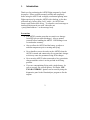
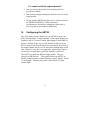
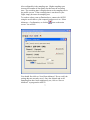
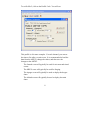
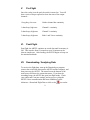
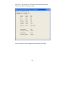
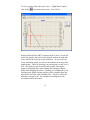
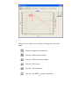
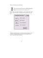
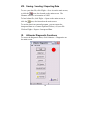
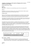
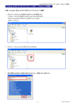
ARTS2 User Manual
Altimeter Recording & Telemetry System
© 2007 Ozark Aerospace, Inc.
Table of Contents
I.
Introduction...................................................................... 2
II.
Mounting the ARTS2...................................................... 4
III.
Connecting the Batteries ............................................. 5
IV.
Configuring the ARTS2................................................. 6
V.
Pre-Flight .......................................................................... 9
VI.
Post-Flight ........................................................................ 9
VII.
Downloading / Analyzing Data.................................... 9
VIII.
Saving / Loading / Exporting Data ........................... 14
IX.
Altimeter Diagnostic Functions................................ 14
X.
Advanced Diagnostics ................................................ 15
Appendix A
Sensors ........................................................... 16
Appendix B
Connector Pinouts ....................................... 18
ARTS Warranty, Terms and Conditions ............................. 19
I.
Introduction
Thank you for purchasing the ARTS2 flight computer by Ozark
Aerospace. Please read this manual carefully and completely
before using the ARTS2 and we highly recommend gaining some
flight experience by using the ARTS2 with a backup, or for data
collection only, before going "solo" with it. An ARTS2 user
forum e-mail list has been set up. To subscribe, send a message to
[email protected] with "subscribe arts
<[email protected]>" as the message body.
Precautions
•
The ARTS2 contains parts that are sensitive to damage
from ESD (electro-static discharge). Always ground
yourself before handling the ARTS2. ESD damage is not
covered under warranty.
•
Always allow the ARTS2 and the battery to adjust to
ambient temperature prior to arming and flying.
•
Never handle or move the rocket or the ARTS2 when the
ARTS2 is armed and connected to live pyrotechnic charges
as this may cause the premature firing of the charges.
•
Never arm the ARTS2 when connected to live pyrotechnic
charges until the rocket is on the pad and in the firing
position.
•
If you are contemplating flying with a single battery, be
sure to use only low current igniters. If in doubt, USE
TWO BATTERIES! Igniters can be tested by using the
diagnostics panel in the DataAnalyzer program to fire the
outputs.
2
The ARTS2 Flight Computer
1
9
This end up
2
3
4
8
7
6
5
1 – Terminal Connector: Connect to your computer using the
supplied serial cable
2 – GPS Connector: Connect to an NMEA2.0 capable GPS to report your
rocket’s position over the telemetry
3 – Programming header: used during production to load firmware
4 – Battery Configuration Jumper: Remove this jumper for use with 2 batteries,
install the jumper for use with a single battery
5 – 9V Main Battery connection, be sure to note polarity marks on board
6 – Power switch connector
7 – 9V Pyro Battery connection, be sure to note polarity marks on board
8 – Option switches:
SW1 (left) selects flight profile 1 (on) or 2 (off)
SW2 (right) selects flight data bank 1 (on) or 2 (off)
9 – Output channel terminals. Channel 1 Apogee, Channel 2 Main
3
II.
Mounting the ARTS2
•
The ARTS2 mounting holes are the same as the original
ARTS.
•
Select a location within
the rocket for the
ARTS2 that is protected
from ejection gasses and
is vented to external
pressure.
•
The ARTS2 must be
mounted vertically with
the arrow on the board
facing up when the
rocket is in the firing
position.
•
The ARTS2 can be
mounted with two ½”
standoffs and #6
machine screws placed
either on the front or
back of the board.
Alternatively, the four
corner holes can be used
with #4 machine screws.
The ARTS2 must be rigidly mounted! The ARTS2
uses the accelerometer to detect both liftoff and
apogee. The ARTS2 will only function properly when
securely mounted.
4
III.
Connecting the Batteries
Use fresh 9V alkaline batteries. A snap type battery clip can be
used. However, a more reliable method is to solder wires directly
to the battery terminals. Observe the correct polarity when
attaching the batteries to the ARTS2, polarity is marked on the
board. Connecting either battery does not power up the ARTS2.
There are separate power and switch connectors and when the
switch is off, there is no load on the batteries. The switch
connector should be connected to an external switch for arming.
Choose a high quality switch.
The ARTS2 can be used with one or two batteries.
When used in the single battery configuration, the ARTS2 is
protected from processor resets when trying to fire high current
igniters. This is done by limiting the current to each igniter. This is
good because the processor will not reset, but it may prevent some
higher-current igniters from firing. If you are planning to fly with
only one battery, be sure to test the igniters (using the Diagnostics
feature in DataAnalyzer) before flying.
When used in the two-battery configuration, the Main battery
powers the processor while the Pyro battery supplies current to the
igniters. The full current capacity of the Pyro Battery is available
to fire the igniters, allowing the full use of high current igniters.
WARNING: Be sure to remove the Battery
Configuration Jumper when using two batteries!
5
Use caution with the output channels!
IV.
•
Always wear eye protection when working with live
pyrotechnic charges.
•
Always shunt charges and igniters until the rocket is in the
firing position
•
Do not arm the ARTS2 until the rocket is on the pad and in
the FIRING POSITION! Unlike some other
accelerometers, the baseline readings are taken only at
power up and are not updated continuously.
Configuring the ARTS2
One of the most powerful features of your ARTS2 system is the
ability to program the 2 output channels. Each output channel can
respond to any of 5 events: Launch, Main Engine Cutoff (MECO),
Apogee, Altitude on the way up, and Altitude on the way down.
Also, a specific time delay between the event and the activation of
the output channel can be set. The most basic configuration would
have Channel 1 set to fire 0.0 seconds after apogee and Channel 2
set to fire 0.0 seconds after a specified Altitude, say 800 feet.
The ARTS2 can hold two different flight profiles. They are
selected via DIP Switch 1. These profiles allow the ARTS2 to
quickly change functions without having to attach a laptop. Profile
1 is an Apogee / Altitude only profile, while Profile 2 is fully
customizable.
6
Also configurable is the sampling rate. Higher sampling rates
increase the number of data points, but decrease the recording
time. The recording time is displayed next to the sampling rate in
the profile screens. If the recording time is too short for your
flight, simply decrease the sampling rate.
To set these values, start up DataAnalyzer, connect the ARTS2
using the serial cable to your computer, and power it on. Select
Altimeter > Configuration, or click the
screen. You will see:
icon on the main
You should first click on “Load from Altimeter” first to verify the
settings that are currently saved. Once the Altitude and or the
Sampling Rate have been satisfactorily set, click on “Save to
Altimeter” to program the ARTS2.
7
To set Profile 2, click on the Profile 2 tab. You will see:
This profile is a bit more complex. For each channel, you can set
the time to fire after a certain event. It is recommended to load the
data from the ARTS2, change the values, and then save the
changes to the ARTS2.
The Launch event will typically be used for air-starts and timed
events.
The MECO event will typically be used for Staging.
The Apogee event will typically be used to deploy the drogue
chute
The Altitude event will typically be used to deploy the main
chute.
8
V.
Pre-Flight
Once the rocket is on the pad, the switch is turned on. You will
hear a series of beeps repeated to show the state of the output
channels :
1 long beep, low tone
Neither channel has continuity
1 short beep, high tone
Channel 1 continuity
2 short beeps, high tone
Channel 2 continuity
3 short beeps, high tone
Both 1 and 2 have continuity
VI.
Post-Flight
Post flight, the ARTS2 continues to record data until its memory is
full. This can take from 82 seconds to up to 26 minutes at the
slowest sample rate. After landing, the ARTS2 begins to beep out
the maximum altitude.
VII.
Downloading / Analyzing Data
To retrieve the flight data, start up the DataAnalyzer program,
connect the serial cable between the ARTS2 and the computer, and
then power up the ARTS2. The status bar on the bottom of the
main screen will show the connection status. If you hear the
ascending beeps, the ARTS2 has gone into flight mode. Check
your cables and Com port settings, and try power cycling the
ARTS2. Once communication has been established, select
Altimeter-> Download Flight Data or click on the
9
icon on the
main screen. A progress bar will appear, and when the download
is done you will see a summary screen:
This screen shows the most pertinent information of the flight.
10
To view a graph of the data, select View -> Flight Data Graph, or
click on the
icon on the main screen. You will see:
Mission Elapsed Time (MET) is shown on the X Axis. On the left
side of the graph is the scale for the Altitude, and on the right side
is the scale for the Velocity and Acceleration. As you move the
cursor around the graph, you will see the numbers at the top of the
graph change. These are showing your current place on the X an Y
axis. The graph can also be moved and zoomed. Moving the
graph is accomplished by right-clicking and holding the button
down while dragging the cursor. Zooming is accomplished by left
clicking on the graph, and moving the yellow crosshairs from the
upper left to the lower right, forming a box. This box will be the
area that is zoomed in on. An example of zooming shows the
acceleration under thrust here:
11
There are a few buttons at the top that will change the view of the
graph.
Zooms the graph out to original size
Turn On / Off barometric altitude
Turn On / Off accelerometer altitude
Turn On / Off Velocity
Turn On / Off Acceleration
Turn On / Off MECO / Apogee / Main lines
12
There are 2 other buttons on the bar:
Saves the current graph to disk as a .BMP (Bitmap) file
Prints the current graph to the selected printer.
There is also a real-time plot function. To access this feature, click
View -> Real Time Plot. The graph will clear itself and you will
see:
Click play, and DataAnalyzer will start drawing the graph. Pause
will pause the graph, and Step will advance the graph one time
unit. To exit, click the Close button.
13
VIII. Saving / Loading / Exporting Data
To save your data file, click Flight -> Save As on the main screen,
icon, also located on the main screen. The
or click the
filename will have an extension of .ODF
To load a data file, click Flight -> Open on the main screen, or
click the
icon, also located on the main screen.
To use the data in an external program, you can export the
interpreted data as a Comma Separated Values (.csv) text file.
Click on Flight-> Export-> Interpreted Data.
IX.
Altimeter Diagnostic Functions
To access the diagnostic menu, click Altimeter-> Diagnostics on
the main screen.
14
The red circle indicates no connection to the ARTS, or no power.
When the ARTS is properly connected and is powered on, the
circle will turn green. The button functions are as follows:
Chirp – Sound a tone on the ARTS.
Radio Test – If you have the Telemetry system, this will
perform a radio check.
Boomer / Sw – Shows the status of both output channels and
the DIP switches.
Sensors – Shows live values of both the accelerometer and
barometric sensors. Try shaking the ARTS to test the
acceleromter.
FW Version – Shows the current Firmware Revision
Download Data – Download the Flight Data
WARNING! Both of the next buttons can be dangerous!
Fire Apogee – Fire output channel 1
Fire Main – Fire output channel 2
X.
Advanced Diagnostics
To re-calibrate, select Advanced-> Calibrate Altimeter from the
Altimeter Diagnostics Menu. The ARTS2 is calibrated during
production, so you should not normally have to calibrate your unit.
15
Appendix A
Sensors
The ARTS2 uses the Analog Devices ADXL78 accelerometer, and
the Motorola MPXA4100A pressure sensor.
The sensors are read using the PIC16F876 processor’s built in 10
bit ADC. To facilitate other ARTS2 functions, both of the sensors
are read at 200Hz regardless of the recorded rate.
Accelerometer
The ADXL78 is set for ±50G, with a resolution of 38mV/G (per its
datasheet). Its output is then passed through a low-pass RC filter
set at ~600Hz.
The calibration value used for computations during flight is
calculated when the ARTS2 enters flight mode, and is the average
of 16 samples. This value is used as a Zero G baseline. This value
is saved in FLASH and is downloaded along with flight data.
The calibration values used for post-flight computations are
calculated by averaging 64 samples at +1g, -1g, and 0. When
commanded (using DataAnalyzer, for example), the ARTS2 will
sum 64 readings at each orientation, and save them into its internal
FLASH. These values are sent along with flight data during
download.
Barometric Sensor
The Motorola MPXA4100A pressure is used to sense air pressure
during flight. The sensor’s output is filtered through an RC filter
before being read by the processor.
16
The calibration value used for computations during flight is
calculated when the ARTS enters flight mode, and is the average
of 16 samples. This value is used as a Zero Altitude baseline. This
value is saved in FLASH and is downloaded along with flight data.
17
Appendix B
Connector Pinouts
For all connectors, Pin 1 is denoted by a square pad.
Terminal (RS232 levels)
1 – GND
2 – RxD
3 – TxD
GPS (RS232 levels)
1 – GND
2 – TxD
3 – RxD
4 - +5V DC
Please note that even though +5V DC is provided on the GPS
connector, it is not recommended to use it a power source.
DO NOT draw more than 10mA from this sources
18
ARTS Warranty, Terms and Conditions
Reasonable care has been exercised in the design, fabrication and
testing of the ARTS by Ozark Aerospace its subcontractors. Ozark
Aerospace warrants the ARTS for a period of 90 days from the
date of purchase. Ozark Aerospace will repair or replace any
ARTS at its discretion during the warranty period. Damage to the
ARTS resulting from rocket flight, recovery failures, or ground
testing is not warranted under any circumstances. ARTS recovery
modes are used for experimental purposes only and shall not be
used where failure would cause injury or property damage. The
purchaser and user of the ARTS accept all risks and
responsibilities for its testing, installation and use. The ARTS
purchaser or user shall not hold Ozark Aerospace or its employees
and contractors liable for any consequential or incidental damages
resulting from its use. First time use of the ARTS signifies
acceptance of these terms. Any modifications made to the ARTS
by the user or connection of equipment not provided by Ozark
Aerospace shall make this warranty void.
19
ARTS2
Altimeter Recording & Telemetry System
Flight Computer