1
WIRELESS DIGITAL VIDEO CAMERA
Design Document
by
Benjamin Tang
Project Advisor: Bruce R. Land
Degree Date: January 2009
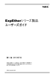
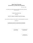
Wireless Digital Video Camera
Table of Contents
Table of Contents
2
List of Figures
3
List of Tables
4
1
Abstract
5
2
Design and implementation
6
2.1
Hardware architecture.................................................................................................... 6
2.1.1 Overview .................................................................................................................... 6
2.1.2 MCU ........................................................................................................................... 7
2.1.3 RF transceiver............................................................................................................ 8
2.1.4 Camera ...................................................................................................................... 8
2.1.5 Power supply ............................................................................................................. 8
2.1.6 Connectors................................................................................................................. 9
2.1.7 Layout ...................................................................................................................... 10
2.1.8 Assembled system................................................................................................... 12
2.2
Embedded software architecture ................................................................................. 13
2.2.1 Overview .................................................................................................................. 13
2.2.2 PC-side embedded software ................................................................................... 13
2.2.3 Camera-side embedded software............................................................................ 14
2.2.4 RF communication ................................................................................................... 14
2.2.5 UART communication .............................................................................................. 15
2.2.6 Video ........................................................................................................................ 15
2.2.7 Microsoft bitmap format ........................................................................................... 16
2.3
Host software architecture ........................................................................................... 18
2.3.1 HostManager ........................................................................................................... 19
2.3.2 SerialManager.......................................................................................................... 19
2.3.3 DataAnalyzer ........................................................................................................... 20
2.3.4 Panel ........................................................................................................................ 21
2.3.5 Recorder .................................................................................................................. 22
3
Appendix
24
3.1
User manual ................................................................................................................. 24
3.1.1 Components............................................................................................................. 24
3.1.2 Set up....................................................................................................................... 24
3.1.3 Video stream............................................................................................................ 25
3.1.4 Recording................................................................................................................. 25
3.1.5 Playback .................................................................................................................. 26
3.1.6 Deletion.................................................................................................................... 26
3.2
Project budget allocation.............................................................................................. 26
3.3
Code............................................................................................................................. 27
3.3.1 Embedded - CodeVision .......................................................................................... 27
3.3.2 Java.......................................................................................................................... 40
2
Wireless Digital Video Camera
List of Figures
Figure 1 - Hardware top level diagram ............................................................................... 6
Figure 2 - MCU circuit board ............................................................................................. 7
Figure 3 - Power supply...................................................................................................... 9
Figure 4 - Schematic diagram for transceiver-camera board.............................................. 9
Figure 5 - PCB layout ....................................................................................................... 11
Figure 6 - PCB cutout for camera-side board ................................................................... 11
Figure 7 - PCB cutout for PC-side board.......................................................................... 11
Figure 8 - Camera-side subsystem.................................................................................... 12
Figure 9 - PC-side subsystem ........................................................................................... 12
Figure 10 - Software architecture top level diagram ........................................................ 13
Figure 11 - PC-side embedded state machine................................................................... 13
Figure 12 - Camera-side embedded state machine ........................................................... 14
Figure 13 - Various methods for capturing image with limited buffer size. From left:
Vertical capture, horizontal capture and box capture ............................................... 16
Figure 14 - Bitmap format ................................................................................................ 17
Figure 15 - One frame captured by the camera................................................................. 18
Figure 16 - Host software state machine for main thread................................................. 18
Figure 17 - Host software UML diagram ......................................................................... 19
Figure 18 - Serial connection status.................................................................................. 20
Figure 19 - Playback selection and execution................................................................... 22
Figure 20 - Delete confirmation request ........................................................................... 23
Figure 21 - Left: PC-side system. Right: camera-side system.......................................... 24
Figure 22 - GUI at start up................................................................................................ 25
3
Wireless Digital Video Camera
List of Tables
Table 1 - GPIO connections................................................................................................ 8
Table 2 - Bitcount section details...................................................................................... 17
Table 3 - Budget allocation............................................................................................... 26
4
Wireless Digital Video Camera
1
Abstract
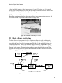
The objective of the project is to build a cheap wireless monitoring system for slowly
varying environments. The system can be used to monitor bee hives, house solar panels
and activities in the compound. The system consists of two IEEE802.15.4 Standardcompliant wireless transceiver modules and microcontrollers, a CMOS digital camera,
PC Graphical User Interface (GUI) and serial port modules. The wireless transceiver
modules communicate between the camera-side embedded system and the PC-side
embedded system. The sequence of images sent from the camera-side transceiver is
received wirelessly by the PC-side transceiver. The PC-side transceiver then transfers the
images to the PC via the PC’s serial port. The sequence of images is displayed in the
GUI. The GUI also features recording, playback of recording and deletion of recording
functions, controllable by the user through the GUI.
5
Wireless Digital Video Camera
2
Design and implementation
This section is divided into hardware architecture, embedded software architecture and
host software architecture. The hardware architecture section describes the functions and
the interactions between the components of the system. The embedded software
architecture section describes the embedded software and protocols that handle wireless
transmission and camera operation. The host software architecture section describes the
PC GUI program that handles user commands and video display.
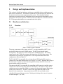
2.1 Hardware architecture
2.1.1
Overview
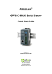
Figure 1 - Hardware top level diagram
The major components of the system are the PC, two microcontrollers (MCU), two
wireless RF transceivers and a CMOS camera. The MCUs used are the Atmel
Atmega644P. The transceivers used are the Atmel AT86RF230 chips. The CMOS
camera used is the C3088 video camera with Omnivision OV6620 image sensor. The
components can generally be grouped into PC-side components and camera-side
components as shown in Figure 1.
The PC-side-MCU is responsible for receiving data via SPI from the RF transceiver
connected to it and then sends the data over to the PC via UART. Reading and writing to
the transceiver’s registers are also done through SPI whereby the MCU is set as the
master and the transceiver the slave.
The camera-side-MCU is responsible for controlling the RF transceiver and the camera
connected to it and receiving image data from the camera. The camera’s image data is
clocked out onto its output pins which are connected to the general purpose input output
(GPIO) ports of the MCU. The MCU retrieves the image data and sends it to the
transceiver for transmission. Image transmission will be discussed further in the
embedded software architecture section. Reading and writing to the camera’s registers
are done through I2C (or TWI).
6
Wireless Digital Video Camera
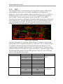
2.1.2
MCU
The Atmega644P MCU is chosen because of its large SRAM capacity (4 KB) which
makes buffering of data easier. It is capable of running at low voltages at low
frequencies. Because of the operating voltage of the RF transceiver is 3.6V, the MCU is
designed to operate at 3.6V as well. At 3.6V, the MCU is guaranteed to run properly
below 10MHz. Therefore the operating frequency of the MCU is set to 8MHz.
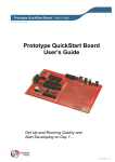
For convenience and ease of verification, I started the design with Professor Land’s MCU
PCB as shown below. The MCU GPIO ports as well as Vcc and Gnd pins are wired to
pins along the edge of the PCB. The order and layout of these pins are important in
designing the PCB for the RF transceiver which will be discussed in the next section.
Figure 2 - MCU circuit board
The PCB is designed for 5V operation with the LM340 5V regulator. I made a slight
modification to the 5V regulator to provide 3.6V to the MCU. The 5V output pin of the
5V regulator is disconnected from the PCB and connected to the input pin of a 3.6V
regulator which is on the RF transceiver PCB. The output of the 3.6V regulator is then
sent back to the MCU PCB via the VCC pins. See Section 2.1.5 for power supply details.
The following table summarizes all the GPIO pins used. There are 11 free GPIO ports
that can still be used for other purposes.
Ports
Pins
Connections
Port A
A0
A1
A2
A3
A4
A5
A6
A7
B0
B1
B2
B3
B4
Y0
Y1
Y2
Y3
Y4
Y5
Y6
Y7
NC
/RST
IRQ
SLP_TR
/SEL
Port B
Comments
Connected to the
camera
Connected to the
RF transceiver
7
Wireless Digital Video Camera
Port C
Port D
B5
B6
B7
C0
C1
D2
D3
D4
MOSI
MISO
SCLK
SCL
SDA
VSYNC
HREF
PCLK
Connected to the
camera
Table 1 - GPIO connections
2.1.3
RF transceiver
The AT86RF230 transceiver operates at a voltage of 3.6V and frequency of 16MHz. A
Balun is used to convert its balanced output signal to unbalanced signal that is fed to the
antenna. The controls of the RF transceiver are connected to Port B of the MCU as
shown in Table 1. Data is transferred between the transceiver and the MCU via SPI. The
SPI control pins are /SEL, MOSI, MISO and SCLK. The MCU is the master whereas the
transceiver is the slave in this SPI relationship. The MCU supplies the clock signal via
the SCLK pin. To initialize communication, the MCU pulls the /SEL pin low and data is
sent to the transceiver through the MOSI pin and received from the transceiver through
the MISO pin. A low signal on the /RST pin resets the transceiver. The SLP_TR pin is
used to start a wireless transmission of a frame of data.
2.1.4
Camera
The C3088 camera operates at a voltage of 5V. It has a built in crystal that oscillates at
17.73MHz. It is capable of taking relatively high resolution images at 101,376 pixels.
The difference in operating voltage between the camera (at 5V) and the rest of the circuit
(at 3.6V) does not pose an issue because only the camera’s digital IO pins are receiving
signals from the rest of the system’s circuit. The camera’s digital IO pins used for I2C
communication are able to accept lower range of voltage values at 3.6V from the MCU
GPIO pins. The image data received by the MCU, no doubt has a maximum voltage
level of 5V, can still be handled appropriately by the MCU.
The C3088 camera has 32 pins in a 2-by-16 pin arrangement. A standard 2x16 connector
is used to connect the camera’s pins to the PCB.
2.1.5
Power supply
The system consists of three power supply sources. The main power supply provides 9V.
The 5V regulator (LM340) converts the 9V DC supply to 5V to power the camera circuit
and the 3.6V regulator. The 3.6V regulator (LP2985) converts the 5V supply to 3.6V to
power the MCU and transceiver circuits.
8
Wireless Digital Video Camera
Figure 3 - Power supply
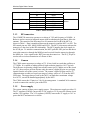
2.1.6
Connectors
As shown in the schematic diagram, there are altogether 5 connectors (J1, J2, J3, J4 and
J5) used in the PC-side and camera-side PCB design. The PC-side PCB has only the
transceiver circuitry whereas the camera-side PCB has both the transceiver and camera
circuitries. Therefore the PC-side PCB only requires one connector - J1. The cameraside PCB uses all 5 connectors – J1, J2, J3, J4 and J5.
Connectors J1 and J2 interface with the GPIO, VCC and GND pins aligned along the
edge of the MCU PCB. Connector J3 interfaces with the pins on the C3088 camera.
Connector J4 is an auxiliary connector that duplicates the camera UV pins for ease of
feature expansion in the future. Connector J5 is also an auxiliary connector that
duplicates the MCU’s Port C pins.
Figure 4 - Schematic diagram for transceiver-camera board
9
Wireless Digital Video Camera
2.1.7
Layout
The cheapest PCB fabrication deal from ExpressPCB limits the size of a double layer
PCB to 3.8”x2.5”, at time of design. I managed to design the layout of the PC-side PCB
that contains only the transceiver circuitry to have a size of about 1.2”x1.2”. The cameraside PCB that has both the transceiver and camera circuitries occupies a board area of
about 3.8”x1.2”. Therefore, I could fit 2 PC-side PCB and 1 camera-side PCB on a
single 3.8”x2.5” PCB with plenty of space between them. The individual PCBs are
meant to be cut out from the bigger piece of PCB as shown in Figure 6 and Figure 7.
2.1.7.1
Top layer
All components, except for the crystal for the RF transceiver circuitry and a capacitor, are
on the top layer. Traces connected to the bypass capacitors are made as short as possible.
To minimize signal reflections caused by impedance mismatch, traces from the RF
transceiver to the balun, and from the balun to the antenna are designed to be symmetric.
Besides that, the traces connecting the RF output pins to the balun have an impedance of
100Ω which is achieved by having trace width of about 0.030 inches for the given
material. [http://circuitcalculator.com/wordpress/2006/01/24/trace-resistance-calculator/]
The trace between the antenna and the output of the balun is designed to have impedance
of 50Ω, which is achieved by having trace width of about 0.1 inches for the given
material. Traces with high frequency signals such as clock signals are kept away from
other signals to prevent coupling of the high frequency signals into the quieter signals.
2.1.7.2
Bottom layer
The bottom layer consists of the ground plane, signal routing, RF transceiver circuitry
crystal and a capacitor. The ground plane is carefully shaped so that the RF ground
plane, analog ground plane and the digital ground plane meet only at the star point of the
RF transceiver chip as advised by the AT86RF230 datasheet. To prevent the crystal from
introducing noise to the ground planes, a cutout of the ground plane is placed around the
crystal.
10
Wireless Digital Video Camera
Figure 5 - PCB layout
Figure 6 - PCB cutout for camera-side board
Figure 7 - PCB cutout for PC-side board
11
Wireless Digital Video Camera
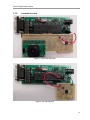
2.1.8
Assembled system
Figure 8 - Camera-side subsystem
Figure 9 - PC-side subsystem
12
Wireless Digital Video Camera
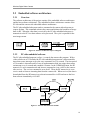
2.2 Embedded software architecture
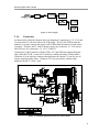
2.2.1
Overview
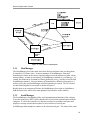
The software architecture of the project consists of the embedded software architecture
and the host software architecture. The embedded software architecture consists of the
PC-side and the camera-side embedded software architecture.
The PC-side embedded subsystem sends a command to the camera-side subsystem to
request for data. This command activates the camera and initiates the broadcast of image
data via RF. When the video data is received by the PC-side embedded subsystem, it
transmits it to the PC Java host software to be processed. The cycle is repeated for the
next image stream.
Figure 10 - Software architecture top level diagram
2.2.2
PC-side embedded software
The PC-side embedded program (radiopc.c) controls the camera-side program. With a
video refresh rate of 32 seconds, the PC-side embedded program runs a microcontroller
timer that creates interrupts to give the start command every 36 seconds. The time period
of 36 seconds is chosen because of ease of implementation with just a timer that creates
an interrupt every 4 seconds and a modulo-9 counter. In the COMMAND state, the RF
transceiver is set to transmit mode and issues a command activate via RF to the cameraside receiver. The activate command is set as 0xA5. Then, the RF transceiver is set to
receive mode to listen to incoming data from the camera-side. When received, the data is
downloaded from the RF transceiver to the microcontroller via SPI and sent to the Java
host software immediately via UART.
Figure 11 - PC-side embedded state machine
13
Wireless Digital Video Camera
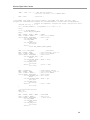
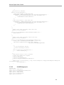
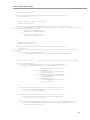
2.2.3
Camera-side embedded software
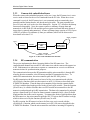
When the camera-side embedded program (radiocam.c) runs, the RF transceiver is set to
receive mode to listen for the activate command from the PC-side. When the activate
command is received, the RF transceiver is set to transmit mode to transmit the start
preamble and the bitmap header, info header and color table. The start preamble has a
size of 4 bytes and is set as the size of the bitmap file. Section 2.2.7 describes the bitmap
format more thoroughly. Next, the camera captures a subframe of image data and
transmits it via RF to the PC-side and this process repeats itself until the entire frame of
image data is captured and transmitted. A frame of bitmap image consists of 47616 bytes
(248x192) of data or 24 subframes (8 lines per subframe) which will be discussed in
more detail in Section 2.2.6
!frame_complete
reset
LISTEN
activate
SEND START
PREAMBLE &
BMP
HEADERS
CAPTURE
SUBFRAME
& TRANSMIT
frame_complete
Figure 12 - Camera-side embedded state machine
2.2.4
RF communication
The project implements the Basic Operating Mode of the RF transceiver. The
communication channel between the PC-side transceiver and the camera-side transceiver
is RF. Both transceivers take turns to operate as a transmitter or a receiver at different
moments in time for synchronization purposes.
The communication between the RF transmitter and the microcontroller is through SPI
whereby the microcontroller is the SPI master and the RF transmitter the slave. To
enable SPI communication, the microcontroller pulls the SPI /SEL pin low.
For RF transmission, the RF transceiver has to be first set to transmit mode with the
rfSetTxMode() function which sets the transceiver in PLL_ON state as described in the
AT86RF230 datasheet. Then the data to be transmitted is put into the transmit buffer
(txFrame) with the data length specified in the txDataLength variable. Then the function
rfSendFrame() is called to send the data over SPI from the microcontroller to the RF
transceiver and packaged up for RF transmission. The data to be transmitted is packaged
up into a frame made up of a byte for frame-transmit command (0x60), a byte for frame
length and the data in the correct sequence. To transmit the frame of packaged data from
the RF transceiver, the microcontroller pulls the SLP_TR pin on the RF transceiver high,
which is taken care of by the function rfSendFrame() as well.
For RF reception, the RF transceiver has to be first set to receive mode with the
rfSetRxMode () function which sets the transceiver in RX_ON state as described in the
AT86RF230 datasheet. Then the microcontroller can listen to incoming RF signals by
14
Wireless Digital Video Camera
checking the IRQ_STATUS register on the RF transceiver. The complete reception of a
frame of data is indicated by the TRX_END bit of the IRQ_STATUS register. Next, the
microcontroller can start retrieving data from the RF transceiver with the
rfRetrieveFrame() function. The frame of data is retrieved through SPI a byte at a time
whereby the microcontroller sends a byte of junk (arbitrary) data just to receive a byte of
data from the RF transceiver. The frame of data is made up of a byte for frame-receive
command (0x20), a byte for frame length, the data and a byte for LQI in the correct
sequence. The LQI information can be used to determine the quality of transmission and
the suspected integrity of the data received.
For data integrity checks, a header for RF frame transmission and reception is optionally
implemented. The header is set to be 0x5A and is inserted between the frame length and
the data in the rfSendFrame() function for transmission. Similarly, the rfRetrieveFrame()
function would be modified to receive the header between the frame length and the data
section in the frame.
2.2.5
UART communication
The project only requires UART transmit mode. The serial communication settings are
chosen to have a baud rate of 38400 bps, 8 bits of data, 2 stop bits and no parity. When
the PC-side embedded system receives data via RF, it immediately sends out the data via
UART. The UART communication speed is the main bottle neck in transmission of data.
Having a higher baud rate however increases transmission errors and this is caused by the
MAX232 chip’s series.
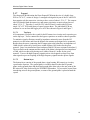
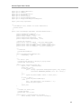
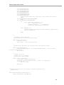
2.2.6
Video
The video stream consists of streaming bitmap images one after another. The C3088
camera uses a progressive scan read out of data. Important signals from the camera for
the implementation of the project are VSYNC, HREF, PCLK and the Y bus. For the
default settings, the VSYNC signal marks the start of the image scan when it goes from
high to low; a high HREF signal provides a guide for each horizontal line of image scan
whereby image data for that particular line is valid at the rising clock edge of PCLK. For
an image of size 248x192, a naïve and simple method to capture an image involves
sampling the data at the Y bus 248 times for each line (guided by each high HREF signal)
by the microcontroller and then repeated for 192 lines when the VSYNC signal goes low.
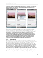
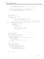
However, to work with the limited size of the microcontroller memory (4KB for
Atmega644P), the capturing process has to be modified unless external memory modules
are added. Buffering of data is needed because of the inherent delay in transmitting the
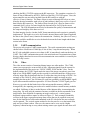
image data. By using only the amount of memory available in the microcontroller as an
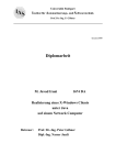
image buffer, three methods of capturing an image can be used – vertical capture,
horizontal capture and box capture as shown in Figure 13. Each rectangle bounded by
red lines in the figure represents an image data section that can be captured at any one
time for the limited-size buffer and transmitted to the PC-side before the next rectangle
can be captured. The vertical capture method is slow because for every horizontal scan,
only one byte of data is taken. However, the camera can be set to run at a higher
frequency without having to worry about missing camera sync signals because there will
15
Wireless Digital Video Camera
be plenty of time for the microcontroller to do processing. The image will not be overexposed because higher camera system frequency results in shorter exposure time. The
horizontal capture method is fast and simple to implement. However, the camera has to
run at a lower frequency so that the microcontroller can keep up with the sync signals as
more processing is performed between the sync signals. At a lower operation frequency,
images tend to be over-exposed due to a longer minimum exposure time. The box
capture method is fast but difficult to implement because of the complexity in merging
the boxes to form a bigger image, either by merging individual box’s bitmap data into a
bigger image’s bitmap data or displaying each box as separate bitmap image in the host
software GUI. Considering all the tradeoffs above, I implemented the horizontal capture
method for the project.
Figure 13 - Various methods for capturing image with limited buffer size. From left: Vertical
capture, horizontal capture and box capture
The C3088 camera with the OV6620 image sensor has a default system clock frequency
of 8.86MHz. Due to voltage constraints that affect the operation frequency, the
microcontroller is run at 8MHz. For the microcontroller to be able to keep up with
sampling the image data with the horizontal capture method and processing it, the camera
system clock frequency has to be adjusted to run at 119.8 kHz.
Writing and reading data to and from the camera registers are done via SCCB (Serial
Camera Control Bus) which is compatible with I2C (Inter-Integrated Circuit) or TWI
(Two Wire Interface). When writing to a camera register, the microcontroller sends the
camera write ID (0xC0) which contains the write control bit ‘0’ in its LSB bit, followed
by the register address and then the data to be written. It is important to note that the
OV6620 sensor takes its register read address from the previous write cycle. Therefore,
when reading from a camera register, the microcontroller first performs a register write
cycle that involves sending the camera write ID (0xC0), followed by the register read
address. Next, the microcontroller sends the camera read ID (0xC1) which contains the
read control bit ‘1’ in its LSB bit before receiving the requested register data from the
camera. A more detailed TWI usage description can be obtained from the Atmega644P
and OV6620 datasheets.
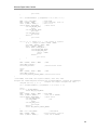
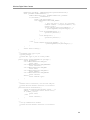
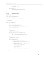
2.2.7
Microsoft bitmap format
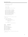
The image data obtained from the camera is made into bitmap format and then sent to the
PC. Bitmap pictures are easily created by the microcontroller and easily converted into
JPEG by the host software to be displayed on the PC. The bitmap format consists of four
16
Wireless Digital Video Camera
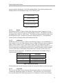
sections: Header, InfoHeader, ColorTable and RasterData. The following illustrates the
bitmap format for a monochrome image of size 248x192 pixel2:
Header (14 Bytes)
InfoHeader (40 Bytes)
ColorTable (1024 Bytes)
RasterData (248x192 Bytes)
Figure 14 - Bitmap format
2.2.7.1
Header
The Header consists of 14 bytes of data in the following sequence: Signature (2 bytes),
FileSize (4 bytes), Reserved (4 bytes) and DataOffset (4 bytes). The Signature section is
by standard set to ‘BM’ or ‘424D’ in hex. The FileSize section describes the total size of
the bitmap file in bytes. The Reserved section is unused and set to 0. The DataOffset
section describes starting location of RasterData in the file.
2.2.7.2
InfoHeader
InfoHeader consists of 40 bytes of data in the following sequence: size of InfoHeader (4
bytes) which is set to 40, width of bitmap (4 bytes), height of bitmap (4 bytes), number of
planes (2 bytes) which is set to 1, Bitcount (2 bytes), types of compression (4 bytes)
which is set to 0 for no compression, compressed size of image (4 bytes) which is set to 0
for no compression, horizontal resolution (4 bytes), vertical resolution (4 bytes), number
of colors used (4 bytes) and number of important colors (4 bytes) which is set to 0 to
denote all colors are important. The Bitcount section describes the number of bits to
represent a pixel as follows:
Number of bits per pixel
Description
1
4
8
16
24
Monochrome palette, 1 color
4-bit palletized, 16 colors
8-bit palletized, 256 colors
16 bit RGB, 65536 colors
24 bit RGB, 1677216 colors
Table 2 - Bitcount section details
The horizontal and vertical resolution sections are denoted in number of pixels per meter.
2.2.7.3
ColorTable
The size of ColorTable section is directly affected by the number of colors used and is
calculated by multiplying number of colors by 4. This is because every color needs to
have specifications, in the following sequence, for red intensity (1 byte), green intensity
17
Wireless Digital Video Camera
(1 byte) and blue intensity (1 byte) and reserved (1 byte). Therefore, for 256 colors (8
bits per pixel configuration) in our case, the size of the ColorTable section is 4x256=1024
bytes with the intensity of each color adjusted accordingly.
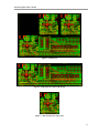
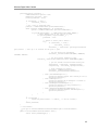
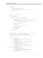
2.2.7.4
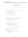
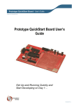
RasterData
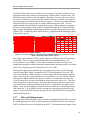
RasterData contains raw data from the camera. Since image compression is not used, the
size of this section is equivalent to the size of the image itself.
Figure 15 - One frame captured by the camera
2.3 Host software architecture
The host software is programmed in Java. The host software is capable of displaying
streams of images on its display panel, recording, playing back or deleting any recordings
selected by the user. It receives incoming data from the PC-side embedded system via
UART and analyzes it. When a full frame of image is received, it updates the display
panel with the latest image and if the recording function is enabled, it stores a copy of the
image in local memory. The application organizes a main thread which executes from
program start up and two minor threads that handle auto-reconnect of serial connection
and recording playback respectively.
Figure 16 - Host software state machine for main thread
18
Wireless Digital Video Camera
ria
se
lM
er
ag
an
_
Figure 17 - Host software UML diagram
2.3.1
HostManager
The HostManager class is the main class where the host software starts executing from.
It extends Java’s JFrame class. It creates instances of SerialManager, Panel and
DataAnalyzer classes in the correct sequence and passes on the instances to other classes
that need them. At start up, an instance of SerialManager (defined as serialManager_) is
created first followed by an instance of Panel (defined as panel_) which receives the said
SerialManager instance. Next, an instance of DataAnalyzer (defined as dataAnalyzer_)
which receives the said SerialManager and Panel instances is created. The GUI classes
are then linked together in a network as shown in Figure 17.
Besides that, as an extension to JFrame, the HostManager class works as a platform to
hold the Panel class, which is the main graphical user interface of the software.
2.3.2
SerialManager
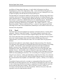
The SerialManager class handles all the serial communication functions of the software.
It uses the open source RXTX API to handle all low level serial communication with the
computer. A call to the enableSerial() function searches for available serial ports and
displays a message window that requests for user selection of a serial port.
SerialManager then attempts to connect to the selected serial port. The status of the serial
19
Wireless Digital Video Camera
connection is updated accordingly on the Panel as shown in Figure 18. A red connection
status bar indicates a no connection; yellow indicates connection in progress; green
indicates a successful connection.
Figure 18 - Serial connection status
When data is received, the SerialManager sends the data to DataAnalyzer using the
function rxData(data). An important function in the SerialManager class is the
autoReconnect() function. Some data can be stuck in the serial engine or go missing if
not flushed out. I realized that disconnecting and then re-connecting the serial
communication solves this problem. Therefore, I implemented the autoReconnect()
function to replace a manual disconnect and reconnect. This function disconnects the
current serial connection and reconnects it with the previously selected serial port.
However, it requires a separate thread to execute because disconnecting the serial
connection from the current thread and reconnecting it hangs the thread.
2.3.3
DataAnalyzer
The DataAnalyzer class analyzes the data received from the SerialManager using the
private function detectPreamble(). The start preamble for the image data frame sent from
the camera-side embedded program is ‘0x00, 0x00, 0xbe, 0x36’ in hex. The end
preamble that marks the end of the image data frame is ‘0xaa, 0x55, 0xa5, 0x5a’. The
detectPreamble() function tracks the data stream to find the start preamble, incrementing
the preambleByteCount_ variable by one with every matched preamble byte. Once all
four bytes of the start preamble are detected, the preambleByteCount_ variable should
have a value of 4 and we know that any subsequent data is the image data. As long as the
end preamble has not been detected yet, DataAnalyzer puts all incoming data into a
queue. When the end preamble is detected, the preambleByteCount_ variable would have
been incremented up to 8 with all four matched end preamble bytes. At this point, we
20
Wireless Digital Video Camera
would have all image data in the queue. A quick check of the queue size allows
DataAnalyzer to verify if the image data is valid. A successful check of the queue size
enables DataAnalyzer to extract the data from the queue to create a bitmap file to be sent
to Panel for display with the function initDisplay(bitmap file).
The DataAnalyzer is designed to handle non-ideal situations. Missing image data frames
would not cause an error in processing the image file because of a image data queue size
check mentioned above. Corrupted image data that still has the correct size is beyond the
host software’s control but is handled by the PC-side embedded program. Besides that,
errors in the serial communication, especially those involving missing start or end
preambles will hamper DataAnalyzer’s algorithm. The variable trackLatch_ is used to
detect this problem. When preambleByteCount_ is stuck at 0 for a long period of time
indicating errors in the serial communication, DataAnalyzer will call the autoReconnect()
function to fix the problem.
2.3.4
Panel
The Panel class is the main graphical user interface of the host software. It houses three
subpanels – Display, Status and Controls. The Display subpanel contains the video
display which is set on a JLabel; the Status subpanel displays the status of the program
from serial connection status to recording, playing, stopping, deleting and auto-reconnect
status; the Controls subpanel allows users to connect and disconnect the serial
communication, record video and select from a list of recorded videos for playback or
deletion.
The Panel class updates its video display using the initDisplay(bitmap File) function.
The function is also responsible for storing the bitmap file into local memory if recording
is enabled. This function is first called by the Panel class itself when initialized to
display a start up screen. Subsequent calls to this function are either made by the
DataAnalyzer when valid image data is completely received or by the Recorder when
playback is in use. The function reads in a bitmap file and creates a JPEG file from it
using Java’s ImageIO class. It is important to use ImageIO.read() function to read in the
JPEG file when updating the JLabel (ie, call setIcon(ImageIO.read(jpeg file))) because
ImageIO.read() does no caching and immediately outputs the file when setIcon function
needs it. If we call setIcon(jpeg file) instead, without using the ImageIO.read() function,
the setIcon function fails to update even with JLabel’s repaint(), validate() or revalidate()
calls.
The playback feature needs to be executed on a separate thread from the current GUI
thread that just fired the playback event. The current GUI thread freezes when it is used
to retrieve the image file from local memory, reinitialize the JLablel and then repeat the
process until the end of the recording. None of JLabel’s repaint(), validate() or
revalidate() built-in functions can solve the problem. Refer to Panel.java code in the
Appendix section for implementation details.
21
Wireless Digital Video Camera
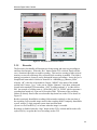
Figure 19 - Playback selection and execution
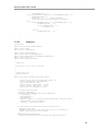
2.3.5
Recorder
The Recorder class handles all functions involving storing and retrieving recordings to
and from local memory. When the “Rec” button on the GUI is clicked, Panel calls the
start() function in Recorder to enable recording. This involves creating a folder in local
memory to store all valid image files collected while recording is enabled. The folder’s
naming convention is chosen to easily distinguish between recordings. It uses the Java’s
SimpleDateFormat which I define its format to be “ddMMMyyyy_hhmmss_SSSa”,
whereby “dd” is the day of the month in 2 digits, “MMM” is the name of the month
spelled with 3 letters, “yyyy” is the year in 4 digits, “hhmmss” is the hour, minute and
second in the standard 12-hour notation, “SSS” is millisecond and “a” is either AM or
PM. An example of a folder name is “10Dec2008_094730_291PM” which represents a
recording that started at 9:47pm on 10 December 2008. The names of the recording
folders are directly listed in the user-selectable drop down box on the GUI as shown in
Figure 19.
Besides a uniquely identifiable recording folder named accordingly to the start time of
the recording, each recorded image stored in the recording folder is uniquely identifiable
as well, using a 13-digit computer system time in milliseconds
(System.currentTimeMillis()) as its name when the image is recorded.
Recording is disabled when the “Stop” button on the GUI is clicked and Recorder calls
updatePlaylist() to update the list of recordings on the GUI.
22
Wireless Digital Video Camera
The Recorder class is also responsible for retrieving recordings and displaying them
during playback. The retrieve(folder name) function is called by Panel when the “Play”
button on the GUI is clicked. This function retrieves all recorded images in the specified
folder and displays them in sequence in a new thread as long as playback is still enabled.
Once the “Stop” button is clicked, the function breaks, returns and stops playback.
The heart of the recording deletion is also handled by Recorder. When the “Delete”
button on the GUI is clicked, with a recording selected from the GUI’s playlist, a deletion
confirmation message is displayed requesting for user confirmation as shown in Figure
20. When user confirmation is obtained, Panel calls Recorder’s deleteFolder(folder
name) function and the folder together with its content is deleted recursively.
Figure 20 - Delete confirmation request
23
Wireless Digital Video Camera
3
Appendix
3.1 User manual
3.1.1
Components
3.1.1.1
Hardware
• PC-side unit
• Camera-side unit
• 1 Serial cable
• 2 DC-9V wall wart
3.1.1.2
Software
• Wireless Digital Video Camera JAR executable file (WiDiVCam.jar)
• RXTX plug-ins
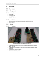
3.1.2
3.1.2.1
Set up
Hardware
Figure 21 - Left: PC-side system. Right: camera-side system
•
•
•
•
Connect the power sockets on the PC-side system and the camera-side system to
the DC wall wart.
Connect the serial port on the PC-side system to the serial port on the PC with the
serial cable.
Point camera to location of interest.
Turn on power for both systems.
24
Wireless Digital Video Camera
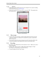
3.1.2.2
Software
• Install and set up the RXTX plug-ins for your computer’s Java system according
to the instructions given at www.rxtx.org.
• Double click on the WiDiVCam.jar file to execute the GUI. The program starts
up as shown below:
Figure 22 - GUI at start up
3.1.3
•
•
3.1.4
•
•
•
Video stream
To start video stream, click the “Connect” button and the select from a pop-up
window the COM Port to which the PC-side hardware system is connected as
shown in Figure 18.
The connection status bar turns green upon successful connection and the video
will start streaming once the program locks onto the camera data stream.
Recording
Recording is only enabled when serial connection is active. Otherwise, the “Rec”
button is disabled.
Click the “Rec” button to start recording and the button changes to “Stop”.
Recordings are automatically saved in local memory.
To stop recording, click the “Stop” button.
25
Wireless Digital Video Camera
3.1.5
•
•
•
3.1.6
•
•
•
Playback
Playback is only enabled when a recording is selected from the drop-down
playlist box that displays the text “Select and play”.
Once a recording is selected, click the “Play” button to start playback. The “Play”
button changes to “Stop”.
To stop playback, click the “Stop” button.
Deletion
Deletion of recording is only enabled when a recording is selected from the dropdown playlist box.
Once a recording is selected, click the “Delete” button to delete the selected
recording.
A window pops up requesting for deletion confirmation. Click the “Yes” button
to continue with deletion.
3.2 Project budget allocation
Expenses
C3088 camera
MCU
RF transceivers
Cables
PCB (1 of 3 used)
Other components
Total
Cost ($)
46.50
Sampled
Sampled
5
60/3 = 20
10
81.50
Table 3 - Budget allocation
26
3.3 Code
3.3.1
Embedded - CodeVision
3.3.1.1
radiopc.c
//radiopc.c
#include
#include
#include
#include
//pc side radio
<mega644.h>
<rf.h>
<stdio.h>
<string.h>
#define TRUE
1
#define FALSE 0
#define TIMEOUT 9
//time to loop back for next photo
unsigned char timer;
void initialize(void);
void initUART(void);
void fetch(void);
interrupt [TIM1_COMPA] void timer1_comp(void)
if(timer>0) --timer;
}
void initialize(void){
initSPI();
initTransceiver();
initUART();
DDRD.2 = 1;
PORTD.2 = 0;
TCCR1A
TCCR1B
OCR1AH
OCR1AL
TIMSK1
=
=
=
=
=
{
//set up SPI for MCU
//set up transceiver
//led indicator
0b00000000; //Clear timer on compare
0b00001101; //Clear timer on compare
0x7A; //produce timer for 4s, need to
0x12;
0b00000010;
//interrupt enable for
match, coupled with TCCR0B settings
match, Timer set up to f/1024
count to 31250=0x7A12, 9 of this yields 36s
compare match A
#asm
sei
//enable interrupts
#endasm
}
void initUART(void){
UBRR0L = 12; // baud rate: 38400 for 8 MHz
UCSR0B = (1<<4)|(1<<3); //enable receiver and transmit
UCSR0C = (1<<7)|(1<<3)|(1<<2)|(1<<1);
//register select; 2 stop bits; 8 bits
}
void fetch(void){
timer = TIMEOUT;
rfSetTxMode();
txDataLength = 1;
txFrame[0] = ACT;
rfSendFrame();
rfSetRxMode();
clearIRQ();
//reset timer
//transceiver set to receive
while(timer>0){
if(rfRxListenNoWait()==1){
PORTD.2 = ~PORTD.2;
rfRetrieveFrame();
//retrieve frame
Wireless Digital Video Camera
}
}
}
void main(void){
initialize();
delay_ms(5000); //initial one-time delay
while(1){
if(timer==0)fetch();
}
}
3.3.1.2
radiocam.c
//radiocam.c
//camera side radio and cam
#include <mega644.h>
#include <rf.h>
#include <stdio.h>
#include <twi.h>
//RF transmission frame constants
#define RF_FRAME_LIMIT
#define PIC_WIDTH
#define PIC_HEIGHT
#define NUM_ROWS_PER_FRAME
#define LOG_NRPF
#define LENGTH_FR
NUM_ROWS_PER_FRAME x WIDTH
#define NUM_RECT_FOR_HEIGHT
#define NUM_64B_IN_FRAME
#define NUM_PER_SEND
clearing sram buffer
#define LOG_NPS
//twi/camera constants
#define CPU_FREQUENCY_HZ
#define TWI_PULLUP_RESISTOR_ENABLE
#define TWI_CAMERA_WRITE_ADDRESS
#define TWI_CAMERA_READ_ADDRESS
#define TWI_DATA_BUFFER_LENGTH
#define CAM_HREF
#define CAM_VSYNC
#define CAM_PCLK
#define TRUE
#define FALSE
128
248
192
8
3
1984
//pic height - divisible by NUM_ROWS_PER_FRAME
//log2 of NUM_ROWS_PER_FRAME
//Length of rectangle frame containing
24
31
64
//HEIGHT/NUM_ROWS_PER_FRAME
//LENGTH_FR/64
//number of bytes sent in one subframe while
6
//log2 of NUM_PER_SEND
8000000
TRUE
0xC0
0xC1
1
PIND.3
PIND.2
PIND.4
1
0
//global
unsigned char twiDataBuffer[TWI_DATA_BUFFER_LENGTH];
unsigned char buff[LENGTH_FR]; //declare huge arrays first memory allocation
//functions
void initialize(void);
void initUART(void);
void resetCam(void);
void writeCam(unsigned int reg, unsigned char value);
unsigned char readCam(unsigned int reg);
void sendBmpHeader(unsigned int height, unsigned int width);
void sendBmpInfoheader(unsigned int height, unsigned int width);
void sendBmpTable(void);
void sendStartPreamble(void);
void sendEndPreamble(void);
void actCapture(void);
void initialize(void){
initSPI();
//set up SPI for MCU
initTransceiver();
//set up transceiver
rfSetTxMode();
initUART();
//initialize UART
DDRD.2 = 1;
//LED indicator
28
Wireless Digital Video Camera
PORTD.2 = 0;
#asm
sei
#endasm
//enable interrupts
}
//initialize UART
void initUART(void){
UBRR0L = 12;
//baud rate: 38400 for 8MHz
UCSR0B = (1<<4)|(1<<3); //enable receiver and transmit
UCSR0C = (1<<7)|(1<<3)|(1<<2)|(1<<1);
//register select; 2 stop bits; 8 bits
}
//reset camera
void resetCam(void){
twiReadRegister(TWI_CAMERA_WRITE_ADDRESS, TWI_CAMERA_READ_ADDRESS, 0x12, 1, twiDataBuffer);
twiDataBuffer[0] |= 0b10000000;
twiWriteRegister(TWI_CAMERA_WRITE_ADDRESS, 0x12, 1, twiDataBuffer);
}
//write to camera register
void writeCam(unsigned int reg, unsigned char value){
twiDataBuffer[0] = value;
twiWriteRegister(TWI_CAMERA_WRITE_ADDRESS, reg, 1, twiDataBuffer);
}
//read from camera register
unsigned char readCam(unsigned int reg) {
twiReadRegister(TWI_CAMERA_WRITE_ADDRESS, TWI_CAMERA_READ_ADDRESS, reg, 1, twiDataBuffer);
return twiDataBuffer[0];
}
//create and send header
void sendBmpHeader(unsigned int height, unsigned int width){
unsigned char bytelow;
unsigned char bytehigh;
unsigned int sizefile = (unsigned int) (1078 + (height*width));
bytelow = (sizefile << 8) >> 8;
bytehigh = sizefile >> 8;
//2 Bytes - BM bitmap signature
txFrame[0] = 'B';
txFrame[1] = 'M';
//4 Bytes - Filesize = 14 + 40 +1024 + HEIGHT * WIDTH
txFrame[2] = bytelow;
txFrame[3] = bytehigh;
txFrame[4] = 0;
txFrame[5] = 0;
//4 Bytes of reserved (= 0)
txFrame[6] = 0;
txFrame[7] = 0;
txFrame[8] = 0;
txFrame[9] = 0;
//4 Bytes of offset for location of raster data
txFrame[10] = 0x36;
txFrame[11] = 0x04;
txFrame[12] = 0;
txFrame[13] = 0;
txDataLength = 14;
rfSetTxMode();
rfSendFrame();
}
//create and send infoheader
void sendBmpInfoheader(unsigned int height, unsigned int width){
unsigned char height_low;
unsigned char height_high;
29
Wireless Digital Video Camera
unsigned char width_low;
unsigned char width_high;
height_low = (height << 8) >> 8;
height_high = height >> 8;
width_low = (width << 8) >> 8;
width_high = width >>8;
//4 Bytes - InfoHeader size: 40
txFrame[0] = 40;
txFrame[1] = 0;
txFrame[2] = 0;
txFrame[3] = 0;
//4 Bytes - width of the image in pixels
txFrame[4] = width_low;
txFrame[5] = width_high;
txFrame[6] = 0;
txFrame[7] = 0;
//4 Bytes - height of the image in pixels
txFrame[8] = height_low;
txFrame[9] = height_high;
txFrame[10] = 0;
txFrame[11] = 0;
//2 Bytes - Number of planes
txFrame[12] = 1;
txFrame[13] = 0;
//2 Bytes bitcount = 8
txFrame[14] = 8;
txFrame[15] = 0;
//4 bytes - type of compression = none
txFrame[16] = 0;
txFrame[17] = 0;
txFrame[18] = 0;
txFrame[19] = 0;
//4 bytes - no compression
txFrame[20] = 0;
txFrame[21] = 0;
txFrame[22] = 0;
txFrame[23] = 0;
//4 bytes - horizontal resolution
txFrame[24] = 0;
txFrame[25] = 0;
txFrame[26] = 0;
txFrame[27] = 0;
//4 bytes - vertical resolution
txFrame[28] = 0;
txFrame[29] = 0;
txFrame[30] = 0;
txFrame[31] = 0;
//4 bytes - num of colors used = 256
txFrame[32] = 0;
txFrame[33] = 1;
txFrame[34] = 0;
txFrame[35] = 0;
//4 bytes - num of important colors = all
txFrame[36] = 0;
txFrame[37] = 0;
txFrame[38] = 0;
txFrame[39] = 0;
txDataLength = 40;
rfSetTxMode();
rfSendFrame();
}
//send color table
void sendBmpTable(void){
unsigned int i;
for(i=0; i<256;i++){
30
Wireless Digital Video Camera
txFrame[0]=i;
txFrame[1]=i;
txFrame[2]=i;
txFrame[3]=0;
txDataLength = 4;
rfSetTxMode();
rfSendFrame();
delay_us(30);
}
}
//send start preamble
void sendStartPreamble(void){
unsigned long size = (unsigned long) (14 + 40 + 1024 + (PIC_HEIGHT*PIC_WIDTH));
txFrame[0] = size >> 24;
txFrame[1] = (size << 8) >> 24;
txFrame[2] = (size << 16) >> 24;
txFrame[3] = (size << 24) >> 24;
txDataLength = 4;
rfSetTxMode();
rfSendFrame();
}
//send end preamble and flusher
void sendEndPreamble(void){
//first 4 bytes are end preamble
txFrame[0] = 0xAA;
txFrame[1] = 0x55;
txFrame[2] = 0xA5;
txFrame[3] = 0x5A;
//next 4 bytes are used to flush java serial so end preamble wont get stuck
txFrame[4] = 0x01;
txFrame[5] = 0x02;
txFrame[6] = 0x03;
txFrame[7] = 0x04;
txDataLength = 8;
rfSetTxMode();
rfSendFrame();
}
//capture photo and send
void actCapture(void){
unsigned int hort;
unsigned int vert;
unsigned int vertFull;
unsigned int bypass=0;
unsigned int trackBypass=0;
unsigned char wDiv2=PIC_WIDTH>>1;
unsigned int count=0;
unsigned char del=0;
unsigned int i, j;
//delay to clear before consider next frame
rfSetTxMode();
for(vertFull=0; vertFull<NUM_RECT_FOR_HEIGHT; vertFull++){
bypass = vertFull<<LOG_NRPF;
//vertFull*NUM_ROWS_PER_FRAME
for(del=0; del<1; del++){
while(!CAM_VSYNC);
while(CAM_VSYNC);
//wait for next frame
while(!CAM_HREF);
while(CAM_HREF);
}
for(trackBypass=0; trackBypass<bypass; trackBypass++){
while(!CAM_HREF);
31
Wireless Digital Video Camera
while(CAM_HREF);
}
for(vert=0; vert<NUM_ROWS_PER_FRAME; vert++){
while(!CAM_HREF);
for(hort=0; hort<wDiv2; hort++){
while(!CAM_PCLK);
buff[count++]=PINA;
while(CAM_PCLK);
while(!CAM_PCLK);
buff[count++]=PINA;
while(CAM_PCLK);
}
while(CAM_HREF);
}
count=0;
txDataLength = NUM_PER_SEND;
for(i=0; i<NUM_64B_IN_FRAME; i++){
for(j=0; j<NUM_PER_SEND; j++){
txFrame[j]=buff[(i<<LOG_NPS) + j];
}
rfSendFrame();
delay_ms(15);
}
//i*64 + j
}
}
void main(void){
initialize();
printf("\r Wireless Video Camera Version 1.0\r");
initTwiMaster(CPU_FREQUENCY_HZ, TWI_PULLUP_RESISTOR_ENABLE);
DDRA = 0x00;
//defined as input - signal from camera
DDRD = (DDRD & 0xE3);
//signals from camera
delay_ms(1500);
resetCam();
delay_ms(2);
writeCam(0x11, 0x25);
delay_ms(2);
// slow down camera clock
while(1){
rfSetRxMode();
rfRxListenAndWait();
PORTD.2 = ~PORTD.2;
//LED indicator
rfRetrieveFrame();
printf("\rRx: %d \r", rxFrame[0]);
if(rxFrame[0] == ACT){
rfSetTxMode();
delay_us(4000);
//delay for PC side to prepare for rx
sendStartPreamble();
printf("\rp\r");
delay_us(30);
sendBmpHeader(PIC_HEIGHT,PIC_WIDTH);
printf("\rh\r");
delay_us(100);
sendBmpInfoheader(PIC_HEIGHT,PIC_WIDTH);
delay_us(6000);
printf("\ri\r");
sendBmpTable();
printf("\rt\r");
#asm("cli");
actCapture();
#asm("sei");
32
Wireless Digital Video Camera
sendEndPreamble();
resetCam();
delay_ms(2);
writeCam(0x11, 0x25);
delay_ms(2);
rxFrame[0] = 0;
}
}
}
3.3.1.3
rf.h
#include <stdio.h>
#include <mega644_uart_tx.h>
#include <delay.h>
//transceiver registers
#define TRX_STATUS
#define TRX_STATE
#define TRX_CTRL_0
#define IRQ_MASK
#define IRQ_STATUS
0x01
0x02
0x03
0x0E
0x0F
//states of transceiver
#define TX_START
#define FORCE_TRX_OFF
#define RX_ON
#define TRX_OFF
#define PLL_ON
#define RX_AACK_ON
#define TX_ARET_ON
0x02
0x03
0x06
0x08
0x09
0x22
0x25
//pins
#define
#define
#define
#define
#define
#define
#define
#define
#define
#define
#define
DDR_MOSI
DDR_MISO
DDR_SCLK
SEL
DDR_SEL
IRQ
DDR_IRQ
SLP_TR
DDR_SLP_TR
RESET
DDR_RESET
#define IRQ_TRX_END
#define ACT
#define HEADER_BYTE
DDRB.5
DDRB.6
DDRB.7
PORTB.4
DDRB.4
PINB.2
DDRB.2
PORTB.3
DDRB.3
PORTB.1
DDRB.1
0x08
0xA5
0x5A
//interrupt
//From PC-side, to activate cam-side
//Header for each frame transmission, receive checks for it
void initSPI(void);
void initTransceiver(void);
void rfSetRxMode(void);
void rfSetTxMode(void);
void rfSendFrame(void);
void rfRxListenAndWait(void);
unsigned char rfRxListenNoWait(void);
void rfRetrieveFrame(void);
void clearIRQ(void);
unsigned char rfReadRegister(unsigned char addr);
void rfWriteRegister(unsigned char addr, unsigned char data);
unsigned char RF_createChecksum(unsigned char *buff, unsigned char size);
unsigned
unsigned
unsigned
unsigned
unsigned
unsigned
char
char
char
char
char
char
txFrame[64];
txDataLength;
rxFrame[64];
rxDataLength;
LQI;
checkStatusIRQ;
//tx buffer, to put data to be sent
//length of data to be sent
//rx buffer, can grab received data here
//length of data to be received
//can check quality of trx
//temp variable to check STATUS_IRQ
33
Wireless Digital Video Camera
//initialize SPI settings
void initSPI(void){
//set directions for MCU SPI ports
DDR_MOSI = 1;
DDR_MISO = 0;
DDR_SCLK = 1;
DDR_SEL = 1;
SPCR0 = 0b01010000;
//enable SPI with MCU as master
SPSR0 = 1;
//double speed
}
//initialize transceiver settings, as receiver first
void initTransceiver(void){
//set port directions
DDR_IRQ = 0;
DDR_SLP_TR = 1;
DDR_RESET = 1;
DDR_SEL = 1;
//set signals
SEL = 1;
RESET = 1;
SLP_TR = 0;
RESET = 0;
delay_us(1);
RESET = 1;
rfWriteRegister(TRX_CTRL_0,0b01001000);
//output current
delay_us(800);
rfWriteRegister(IRQ_MASK,0b00001000);
//TRX_END interrupt
delay_us(200);
rfWriteRegister(TRX_STATE,FORCE_TRX_OFF);
delay_us(1880);
rfWriteRegister(TRX_STATE,RX_ON); //init as rx
delay_us(200);
}
//set transceiver in receive mode
void rfSetRxMode(void){
rfWriteRegister(TRX_STATE,FORCE_TRX_OFF);
delay_us(1880);
rfWriteRegister(TRX_STATE,RX_ON);
delay_us(200);
}
//set transceiver in transmit mode
void rfSetTxMode(void){
rfWriteRegister(TRX_STATE,FORCE_TRX_OFF);
delay_us(1880);
rfWriteRegister(TRX_STATE,PLL_ON);
delay_us(200);
}
//send out frame with txFrame and txDataLength filled
void rfSendFrame(void){ //send out frame
unsigned char i;
rfWriteRegister(TRX_STATE,PLL_ON);
SEL = 0; //enable SPI transfer
SPDR0 = 0b01100000; //frame tx command
while((SPSR0&0x80) == 0); //wait till done
SPDR0 = txDataLength; //send frame length
while((SPSR0&0x80) == 0); //wait till done
for(i=0; i<txDataLength; i++){
//send out data
SPDR0 = txFrame[i];
while((SPSR0&0x80) == 0); //wait till done
}
SEL = 1; //end SPI transfer
SLP_TR = 1;
//release frame via RF
34
Wireless Digital Video Camera
delay_us(1);
SLP_TR = 0;
//make sure transmit is complete
do {
if (IRQ != 0)
checkStatusIRQ = rfReadRegister(IRQ_STATUS);
} while ((checkStatusIRQ & IRQ_TRX_END) == 0);
checkStatusIRQ = 0;
}
//listen and won't return until detected incoming data
void rfRxListenAndWait(void){
do {
if (IRQ != 0)
checkStatusIRQ = rfReadRegister(IRQ_STATUS);
} while ((checkStatusIRQ & IRQ_TRX_END) == 0);
checkStatusIRQ = 0;
}
//checks for incoming data then return boolean if any
unsigned char rfRxListenNoWait(void){
unsigned received = 0;
if (IRQ !=0) {
checkStatusIRQ = rfReadRegister(IRQ_STATUS);
if ((checkStatusIRQ & IRQ_TRX_END) != 0) received = 1;
else received = 0;
}
checkStatusIRQ = 0;
return received;
}
//retrieve frame of data
void rfRetrieveFrame(void){
unsigned char i;
unsigned char data;
SEL = 0; //enable SPI transfer
SPDR0 = 0b00100000; //frame receive command
while ((SPSR0&0x80)==0);
//wait till done
SPDR0 = 0xAA; //arbitrary data to rx a byte
while((SPSR0&0x80)==0);
rxDataLength = SPDR0; //receive rxDataLength
for (i=0; i<rxDataLength; i++){
SPDR0 = 0xAA;
while ((SPSR0&0x80)==0);
//wait till done
data = SPDR0;
uart_send_byte(data); //send to uart
rxFrame[i] = data;
}
SPDR0 = 0xAA;
while ((SPSR0&0x80)==0);
//wait till done
LQI = SPDR0;
//uart_send_byte(LQI);
SEL = 1;
//end SPI transfer
}
//clear IRQ
void clearIRQ(void){
checkStatusIRQ = rfReadRegister(IRQ_STATUS);
checkStatusIRQ = 0;
}
//read transceiver's register given address
unsigned char rfReadRegister(unsigned char addr) {
unsigned char temp;
SEL = 0;
//enable spi transfer
SPDR0 = 128 + (addr & 0b00111111); //6-bit address
while((SPSR0&0x80) == 0); //Wait till done
temp = SPDR0;
SPDR0 = 0xAA; //send arbitrary data to receive back register data
while((SPSR0&0x80) == 0); //Wait till done
35
Wireless Digital Video Camera
SEL = 1;
return SPDR0; //data read from register
}
//write transceiver's register given address and data to be written
void rfWriteRegister(unsigned char addr, unsigned char data) {
unsigned char temp;
SEL = 0;
//enable spi transfer
SPDR0 = 192 + (addr & 0b00111111);
while((SPSR0&0x80) == 0); //Wait till done
temp = SPDR0;
SPDR0 = data;
while ((SPSR0&0x80) == 0); //Wait till done
SEL = 1;
//end spi transfer
}
//create simple checksum
unsigned char RF_createChecksum(unsigned char *buff, unsigned char size){ //see wikipedia checksum
unsigned char i=0;
unsigned char chks=0;
while(i++<size){
//sum up data
chks = chks + *buff++;
}
chks = chks&0xff;
chks = ~chks + 1; //get 2's-complement: flip bits add 1
printf("CHKS: %x \r", chks);
return chks;
}
3.3.1.4
mega644_uart_tx.h
#define UDRE0 5
void uart_send_byte_array(unsigned char *data, unsigned int length);
void uart_send_byte(unsigned char data);
//send byte array with specified length
void uart_send_byte_array(unsigned char *data, unsigned int length) {
unsigned int counter = 0;
while (counter++ < length) {
while ( !( UCSR0A & (1<<UDRE0)) );
// Wait for buffer
UDR0 = *data++;
// Send out data
}
}
//send byte
void uart_send_byte(unsigned char data) {
while ( !( UCSR0A & (1<<UDRE0)) );
UDR0 = data;
}
3.3.1.5
// Wait buffer
// Send out data
twi.h
//twi.h
#define TW_MAX_RETRY
5
//twi define
#define TWI_FREQUENCY_HZ
#define TWI_READ
#define TWI_WRITE
#define TWI_GENERAL_ADDRESS
#define TWSR_MASK
100000
1
0
0
0xF8
//TWCR register constants
#define TWINT
0b10000000
#define TWEA
0b01000000
#define TWSTA
0b00100000
#define TWSTO
0b00010000
36
Wireless Digital Video Camera
#define TWWC
#define TWEN
#define TWIE
0b00001000
0b00000100
0b00000001
//twi master tx status codes
#define TWI_MT_ADR_ACK
#define TWI_MT_ADR_NACK
#define TWI_MT_DATA_ACK
#define TWI_MT_DATA_NACK
0x18
0x20
0x28
0x30
//
//
//
//
SLA+W tramsmitted, ACK received
SLA+W tramsmitted, NACK received
Data byte tramsmitted, ACK received
Data byte tramsmitted, NACK received
//twi master rx status codes
#define TWI_MR_ADR_ACK
#define TWI_MR_ADR_NACK
#define TWI_MR_DATA_ACK
#define TWI_MR_DATA_NACK
0x40
0x48
0x50
0x58
//
//
//
//
SLA+R tramsmitted, ACK received
SLA+R transmitted, NACK received
Data byte received, ACK tramsmitted
Data byte received, NACK tramsmitted
0xA8
0xB0
// Own SLA+R received, ACK returned
// Arb lost in SLA+R/W as Master, own SLA+R received,
0xB8
0xC0
0xC8
// Data byte TWDR transmitted, ACK received
// Data byte TWDR transmitted, NACK received
// Last data byte in TWDR transmitted, ACK received
0x60
0x68
// Own SLA+W received, ACK returned
// Lost arb in SLA+R/W as Master, own SLA+W received,
0x70
0x78
// General call addr received, ACK returned
// Lost arb in SLA+R/W as Master, general call addr
0x80
// Previously addressed with own SLA+W, data received,
0x88
// Previously addressed with own SLA+W, data received,
0x90
// Previously addressed with general call, data
0x98
// Previously addressed with general call, data
0xA0
// STOP condition or repeated START condition received
0x08
0x10
0x38
0xF8
0x00
//
//
//
//
//
//twi slave tx status codes
#define TWI_ST_ADR_ACK
#define TWI_ST_ADR_ACK_M_ARB_LOST
ACK returned
#define TWI_ST_DATA_ACK
#define TWI_ST_DATA_NACK
#define TWI_ST_DATA_ACK_LAST_BYTE
//twi slave rx status codes
#define TWI_SR_ADR_ACK
#define TWI_SR_ADR_ACK_M_ARB_LOST
ACK returned
#define TWI_SR_GEN_ACK
#define TWI_SR_GEN_ACK_M_ARB_LOST
received, ACK returned
#define TWI_SR_ADR_DATA_ACK
ACK returned
#define TWI_SR_ADR_DATA_NACK
NACK returned
#define TWI_SR_GEN_DATA_ACK
received, ACK returned
#define TWI_SR_GEN_DATA_NACK
received, NACK returned
#define TWI_SR_STOP_RESTART
as slave
//other
#define
#define
#define
#define
#define
status codes
TWI_START
TWI_REP_START
TWI_ARB_LOST
TWI_NO_STATE
TWI_BUS_ERROR
//function return status
#define TWI_SUCCESS
#define TWI_INVALID_STATUS_ERROR
#define TWI_NO_ACK_ERROR
#define TWI_INVALID_SLA_ERROR
#define TWI_ARB_LOST_ERROR
#define TWI_NO_DATA_ERROR
START transmitted
Repeated START transmitted
Arbitration lost
No relevant state information
Bus error with illegal START/STOP conditions
0
1
2
3
4
5
//initialize
void initTwiMaster(unsigned long cpu_freq, unsigned char pullup_resistor) {
float temp;
if (pullup_resistor) {
DDRC.0 = 0;
DDRC.1 = 0;
PORTC.0 = 1;
PORTC.1 = 1;
}
temp = (float) cpu_freq / (float) TWI_FREQUENCY_HZ;
37
Wireless Digital Video Camera
TWBR = (temp - 16) / 2 ;//TWI Bit Rate Register
//I2C Freq = CPU Freq / (16 + 2*TWBR*4^TWPS)
TWSR = 0x00;
//prescaler 1
}
//send START, send SLA+W, send register address, send START, send SLA+R, grab data, STOP
unsigned char twiReadRegister(unsigned char slaveWriteAddress, unsigned char slaveReadAddress,
unsigned int regAddress, unsigned char length, unsigned char *data){
unsigned char sla, i, n = 0;
sla = slaveWriteAddress | (((regAddress >> 8) & 0x07) << 1);
retry:
if (n++ >= TW_MAX_RETRY)
return TWI_NO_ACK_ERROR;
begin:
TWCR = TWINT | TWSTA | TWEN; //START
while (!(TWCR & TWINT));
//wait for tx (TWINT)
switch (TWSR & TWSR_MASK) {
//check status
case TWI_REP_START:
case TWI_START:
//OK
break;
case TWI_ARB_LOST:
goto begin;
default:
return TWI_INVALID_STATUS_ERROR;
}
TWDR = sla | TWI_WRITE;
TWCR = TWINT | TWEN;
while (!(TWCR & TWINT));
switch (TWSR & TWSR_MASK) {
case TWI_MT_ADR_ACK:
break;
case TWI_MT_ADR_NACK:
goto retry;
case TWI_ARB_LOST:
goto begin;
default:
goto error;
}
//send SLA+W
//clear interrupt, start tx
//wait for tx (TWINT)
//check status
//OK
TWDR = regAddress;
TWCR = TWINT | TWEN;
while (!(TWCR & TWINT));
switch (TWSR & TWSR_MASK) {
case TWI_MT_DATA_ACK:
break;
case TWI_MT_DATA_NACK:
goto quit;
case TWI_ARB_LOST:
goto begin;
default:
goto error;
}
//send register address
//clear interrupt, start tx
//wait for tx (TWINT)
//check status
//OK -> break
//NACK -> retry
//error -> STOP
//NACK -> quit
//error -> STOP
//Stop/pause TWI interface
TWCR = 0;
delay_us(2);
TWCR = TWINT | TWSTA | TWEN;
while (!(TWCR & TWINT));
switch (TWSR & TWSR_MASK) {
case TWI_START:
case TWI_REP_START:
break;
case TWI_ARB_LOST:
goto begin;
default:
//send START
//wait for tx
//check status
38
Wireless Digital Video Camera
goto error;
}
sla = slaveReadAddress |(((regAddress >> 8) & 0x07) << 1);
TWDR = sla | TWI_READ;
//send SLA+R
TWCR = TWINT | TWEN;
//clear interrupt, start tx
while (!(TWCR & TWINT));
//wait for tx
switch (TWSR & TWSR_MASK) {
//check status
case TWI_MR_ADR_ACK:
break;
case TWI_MR_ADR_NACK:
goto quit;
case TWI_ARB_LOST:
goto begin;
default:
goto error;
}
for (i = 0; i < length; i++) { //get content of register
if (i == (length-1)) TWCR = TWINT | TWEN;
else TWCR = TWINT | TWEN | TWEA;
while (!(TWCR & TWINT));
switch (TWSR & TWSR_MASK) {
case TWI_MR_DATA_NACK:
case TWI_MR_DATA_ACK:
*data++ = TWDR;
break;
default:
goto error;
}
}
TWCR = TWINT | TWSTO | TWEN;
while(TWCR & TWSTO);
return TWI_SUCCESS;
//STOP
//return success status
error:
quit:
TWCR = TWINT | TWSTO | TWEN;
//STOP
while(TWCR & TWSTO);
return TWI_INVALID_STATUS_ERROR;//return error status
}
//send START, send SLA+W, send register address, write data, STOP
unsigned char twiWriteRegister(unsigned char slaveWriteAddress, unsigned int regAddress,
unsigned char length, unsigned char *data) {
unsigned char sla, i, n = 0;
sla = slaveWriteAddress |(((regAddress >> 8) & 0x07) << 1);
retry:
if (n++ >= TW_MAX_RETRY)
return TWI_NO_ACK_ERROR;
begin:
TWCR = TWINT | TWSTA | TWEN; //send START
while (!(TWCR & TWINT));
//wait for tx (TWINT)
switch (TWSR & TWSR_MASK) {
//check status
case TWI_REP_START:
case TWI_START:
//OK
break;
case TWI_ARB_LOST:
goto begin;
default:
return TWI_INVALID_STATUS_ERROR;
}
TWDR = sla | TWI_WRITE;
TWCR = TWINT | TWEN;
while (!(TWCR & TWINT));
//send SLA+W
//clear interrupt, start tx
//wait for tx (TWINT)
39
Wireless Digital Video Camera
switch (TWSR & TWSR_MASK) {
//check status
case TWI_MT_ADR_ACK:
//OK
break;
case TWI_MT_ADR_NACK: //NACK -> retry
goto retry;
case TWI_ARB_LOST:
goto begin;
default:
//error -> STOP
goto error;
}
TWDR = regAddress;
TWCR = TWINT | TWEN;
while (!(TWCR & TWINT));
switch (TWSR & TWSR_MASK) {
case TWI_MT_DATA_ACK:
break;
case TWI_MT_DATA_NACK:
goto quit;
case TWI_ARB_LOST:
goto begin;
default:
goto error;
}
//send register address
//clear interrupt, start tx
//wait for tx (TWINT)
//check status
//OK
//NACK -> quit
//error -> STOP
for (i = 0; i < length; i++) { //write data
TWDR = *data++;
TWCR = TWINT | TWEN;
while (!(TWCR & TWINT));
switch (TWSR & TWSR_MASK) {
//check status
case TWI_MT_DATA_ACK: //OK
break;
case TWI_MT_DATA_NACK: //write protected? -> quit
goto quit;
case TWI_ARB_LOST:
goto begin;
default:
//error -> STOP
goto error;
}
}
TWCR = TWINT | TWSTO | TWEN;
while(TWCR & TWSTO);
return TWI_SUCCESS;
//STOP
error:
quit:
TWCR = TWINT | TWSTO | TWEN; //STOP
while(TWCR & TWSTO);
return TWI_INVALID_SLA_ERROR;
}
3.3.2
3.3.2.1
Java
HostManager.java
package host;
import java.awt.event.ActionEvent;
import java.io.IOException;
import javax.comm.PortInUseException;
import javax.comm.UnsupportedCommOperationException;
import javax.swing.JFrame;
import javax.swing.JMenu;
import javax.swing.JMenuBar;
import javax.swing.JMenuItem;
import javax.swing.JOptionPane;
40
Wireless Digital Video Camera
/**
* HostManager class
* Main
* @author bentzx
*/
public class HostManager extends JFrame{
private static final long serialVersionUID = 1L;
private Panel panel_;
//Panel
private DataAnalyzer dataAnalyzer_;
//DataAnaylzer
private SerialManager serialManager_;
//SerialManager
private JMenuItem helpMenuAbout_;
private JMenuItem fileMenuExit_;
private JMenu fileMenu_;
private JMenu helpMenu_;
private JMenuBar menuBar_;
public static final String PROJECT_NAME = "Wireless Video Camera";
/**
* HostManager constructor
* @throws IOException
* @throws UnsupportedCommOperationException
* @throws PortInUseException
*/
public HostManager() throws IOException, UnsupportedCommOperationException, PortInUseException{
super();
//create in correct sequence
serialManager_ = new SerialManager(this);
panel_ = new Panel(serialManager_);
dataAnalyzer_ = new DataAnalyzer(panel_, serialManager_);
initComponents();
}
/**
* Initialize components on frame
*/
private void initComponents(){
setDefaultCloseOperation(javax.swing.WindowConstants.EXIT_ON_CLOSE);
setBackground(new java.awt.Color(255, 255, 255));
setResizable(false);
setTitle(HostManager.PROJECT_NAME);
getContentPane().add(panel_, java.awt.BorderLayout.CENTER);
initMenu();
initListeners();
pack();
setLocation(250, 250);
setVisible(true);
}
/**
* Initialize menu bar items
*/
private void initMenu(){
menuBar_ = new javax.swing.JMenuBar();
fileMenu_ = new javax.swing.JMenu();
fileMenuExit_ = new javax.swing.JMenuItem();
helpMenu_ = new javax.swing.JMenu();
helpMenuAbout_ = new javax.swing.JMenuItem();
fileMenu_.setText("File");
fileMenuExit_.setText("Exit");
fileMenu_.add(fileMenuExit_);
menuBar_.add(fileMenu_);
helpMenu_.setText("Help");
helpMenuAbout_.setText("About");
helpMenu_.add(helpMenuAbout_);
menuBar_.add(helpMenu_);
setJMenuBar(menuBar_);
}
41
Wireless Digital Video Camera
/**
* Initialize all listeners.
*/
private void initListeners() {
//add action listener to exit menu item
fileMenuExit_.addActionListener(new java.awt.event.ActionListener() {
public void actionPerformed(java.awt.event.ActionEvent evt) {
fileMenuExitActionPerformed(evt);
}
});
//add action listener to about menu item
helpMenuAbout_.addActionListener(new java.awt.event.ActionListener() {
public void actionPerformed(java.awt.event.ActionEvent evt) {
helpMenuAboutActionPerformed(evt);
}
});
}
/**
* Handle action event concerning "exit" menu item.
* @param evt The ActionEvent
*/
private void fileMenuExitActionPerformed(ActionEvent evt) {
System.exit(0);
}
/**
* Handle action event concerning "about" menu item.
* @param evt The ActionEvent
*/
private void helpMenuAboutActionPerformed(ActionEvent evt) {
String[] msg = {HostManager.PROJECT_NAME + " Ver 1.0"};
JOptionPane.showMessageDialog(this, msg, "About",
JOptionPane.INFORMATION_MESSAGE);
}
/**
* To get DataAnalyzer instance
* @return DataAnalyzer instance
*/
public DataAnalyzer getDataAnalyzer() {
return dataAnalyzer_;
}
/**
* Main method called at start of program.
* @param argv Command line argument
* @throws IOException
* @throws PortInUseException
* @throws UnsupportedCommOperationException
*/
public static void main(String [] argv) throws IOException, UnsupportedCommOperationException,
PortInUseException {
new HostManager();
}
}
3.3.2.2
SerialManager.java
package host;
import java.io.IOException;
import java.util.TooManyListenersException;
import java.io.InputStream;
import java.io.OutputStream;
import java.util.Enumeration;
import java.util.Vector;
42
Wireless Digital Video Camera
import
import
import
import
import
import
import
gnu.io.CommPortIdentifier;
gnu.io.CommPort;
gnu.io.PortInUseException;
gnu.io.SerialPort;
gnu.io.SerialPortEvent;
gnu.io.SerialPortEventListener;
gnu.io.UnsupportedCommOperationException;
import javax.swing.JOptionPane;
/**
* SerialManager class, handles all serial communication
* @author bentzx
*
*/
public class SerialManager implements SerialPortEventListener {
private
private
private
private
private
HostManager hostManager_;
SerialPort serialPort_ = null;
String comPort_ = null;
InputStream inputStream_ = null;
OutputStream outputStream_ = null;
//Serial port settings:
private static final int
private static final int
private static final int
private static final int
PARITY = SerialPort.PARITY_NONE;
STOPBITS = SerialPort.STOPBITS_2;
BAUD = 38400; //38400, 57600, 115200
DATABITS = SerialPort.DATABITS_8;
/**
* Constructor
* @param hM HostManager
*/
public SerialManager(HostManager hM) {
hostManager_ = hM;
}
/**
* To select a port
* @param msg The message to display in pop-up window
* @return The selected port
*/
private String selectPort(String msg) {
Object[] list = listPorts(true);
String port = null;
if (list.length > 0) {
port = (String) JOptionPane.showInputDialog(null, msg, "Input",
JOptionPane.INFORMATION_MESSAGE, null, list, list[0]);
}
else {
System.out.println("Must connect a serial port");
}
if (port == null) {
System.out.println("Exiting");
} else {
port = port.substring(0, port.indexOf(" - "));
System.out.println(port);
}
return port;
}
/**
* Searches for serial ports
* @param available
* @return The list of ports
*/
private Object[] listPorts(boolean available) {
Vector <String> result = new Vector <String>();
43
Wireless Digital Video Camera
Enumeration portEnum = CommPortIdentifier.getPortIdentifiers();
while (portEnum.hasMoreElements()) {
CommPortIdentifier com = (CommPortIdentifier) portEnum
.nextElement();
if (available) {
switch (com.getPortType()) {
case CommPortIdentifier.PORT_SERIAL:
try {
// Test open port to see if it's available
CommPort thePort = com.open("commtest", 50);
thePort.close();
result.add(new String(com.getName()+" - "
+ getPortTypeName(com.getPortType())));
}
catch (PortInUseException e) {
System.err.println(e);
}
catch (Exception e) {
System.err.println(e);
}
}
} else {
result.add(new String(com.getName() + " - "
+ getPortTypeName(com.getPortType())));
}
}
return result.toArray();
}
/**
* Determines what type of port
* @param portType
* @return The type of port in String format
*/
private String getPortTypeName(int portType) {
switch (portType) {
case CommPortIdentifier.PORT_I2C:
return "I2C";
case CommPortIdentifier.PORT_PARALLEL:
return "Parallel";
case CommPortIdentifier.PORT_RAW:
return "Raw";
case CommPortIdentifier.PORT_RS485:
return "RS485";
case CommPortIdentifier.PORT_SERIAL:
return "Serial";
default:
return "unknown type";
}
}
/**
* Enables serial connection, user chooses COM port
* @return Boolean whether connection is successful
*/
protected boolean enableSerial(){
System.out.println("Initializing serial... ");
comPort_ = selectPort("Select Serial Port");
if (comPort_==null){
return false;
} else {
return converse();
}
}
/**
* Sets up communication channel
* @return boolean whether connection is successful
*/
44
Wireless Digital Video Camera
protected boolean converse() {
CommPortIdentifier portId = null;
Enumeration portList = null;
boolean portFound = false;
if (serialPort_ != null) {
serialPort_.close();
}
// Get a list of available ports
portList = CommPortIdentifier.getPortIdentifiers();
while (portList.hasMoreElements() && !portFound) {
portId = (CommPortIdentifier) portList.nextElement();
if (portId.getPortType() == CommPortIdentifier.PORT_SERIAL) {
// Tests whether this is the com port we want
if (portId.getName().equals(comPort_)) {
portFound = true;
/* listen to serial port's events */
try {
if (serialPort_ != null) {
serialPort_.close();
}
serialPort_ = (SerialPort) portId.open("videoCam
port",10000); // wait up to 10 seconds for the port to open
// set the Serial Port parameters
serialPort_.setSerialPortParams(BAUD, DATABITS,
STOPBITS, PARITY);
// set flow control hardware to none
serialPort_.setFlowControlMode(SerialPort.FLOWCONTROL_NONE);
// get the streams associated with serial port
inputStream_ = serialPort_.getInputStream();
outputStream_ = serialPort_.getOutputStream();
// start listening for events
serialPort_.addEventListener(this);
serialPort_.notifyOnDataAvailable(true);
} catch (PortInUseException e) {
System.out.println("Serial Port already in use.");
System.err.println(e);
} catch (IOException e) {
System.out.println("An IO Exception occurred.");
System.err.println(e);
} catch (TooManyListenersException e) {
System.out.println("too many listeners.");
System.err.println(e);
} catch (UnsupportedCommOperationException e) {
System.out.println("Unknown comm Exception.");
System.err.println(e);
}
}
}
}
if (!portFound) {
System.out.println("Port " + comPort_ + " was not found!");
}
return portFound;
}
/* (non-Javadoc)
* @see gnu.io.SerialPortEventListener#serialEvent(gnu.io.SerialPortEvent)
*/
public void serialEvent(SerialPortEvent event) {
switch (event.getEventType()) {
45
Wireless Digital Video Camera
case
case
case
case
case
case
case
case
SerialPortEvent.BI:
SerialPortEvent.OE:
SerialPortEvent.FE:
SerialPortEvent.PE:
SerialPortEvent.CD:
SerialPortEvent.CTS:
SerialPortEvent.DSR:
SerialPortEvent.RI:
System.out.println("Bad data. Ignore most recent received data packet");
break;
case SerialPortEvent.OUTPUT_BUFFER_EMPTY:
break;
case SerialPortEvent.DATA_AVAILABLE:
try {
while (inputStream_.available() > 0) {
int i = inputStream_.read();
System.out.println("
" + intToHex(i));
hostManager_.getDataAnalyzer().rxData(i);
}
}
catch (IOException e) {
System.err.println("IO Exception occurred reading fr inputStream.");
System.err.println(e);
}
break;
}
}
/**
* Disconnects serial connection
* @return Boolean false for disconnected serial
*/
public boolean disconnect() {
serialPort_.close();
return false; // false for disconnection
}
/**
* Automatically disconnects and reconnects serial with previous settings
*/
public void autoReconnect(){
AutoReconnectThread aRecon = new AutoReconnectThread(this); //use new thread,
otherwise program freezes
aRecon.start();
}
/**
* Converts int to hex
* @param i Int to be converted
* @return Hex in String format
*/
private String intToHex(int i) {
//String hex = Integer.toHexString(i);
String hex = Integer.toHexString(0x100 | (0x0ff & i)).substring(1);
if (hex.length() == 1) {
hex = "0" + hex;
}
return hex;
}
}
/**
* Requires this thread for auto reconnect, otherwise, program freezes
* @author bentzx
*
*/
class AutoReconnectThread extends Thread {
private SerialManager serialManager_;
46
Wireless Digital Video Camera
public AutoReconnectThread(SerialManager sM){
serialManager_ = sM;
}
public void run() {
System.out.println("Auto-reconnecting");
serialManager_.converse();
}
}
3.3.2.3
DataAnalyzer.java
package host;
import
import
import
import
import
java.io.File;
java.io.FileNotFoundException;
java.io.FileOutputStream;
java.io.IOException;
java.util.concurrent.ConcurrentLinkedQueue;
/**
* DataAnalyzer class, handles all data analysis
* @author bentzx
*
*/
public class DataAnalyzer {
private Panel panel_;
private SerialManager serialManager_;
private int preambleByteCount_ = 0;
public static final int BMP_SIZE = 48694;
private ConcurrentLinkedQueue<Integer> queue_ = null;
private int trackLatch_ = 0;
/**
* Constructor
* @param p Panel
* @param sM SerialManager
*/
public DataAnalyzer(Panel p, SerialManager sM){
panel_ = p;
serialManager_ = sM;
queue_ = new ConcurrentLinkedQueue<Integer>();
}
/**
* Receives serial port data
* @param i
*/
public void rxData(int i){
detectPreamble(i);
System.out.println(preambleByteCount_);
if (preambleByteCount_>=4 && preambleByteCount_ <=8){
queue_.add(new Integer(i));
}
if (preambleByteCount_ == 8){
System.out.println("qS: " + queue_.size());
if (queue_.size()==BMP_SIZE+5){
createPic();
}
preambleByteCount_ = 0;
queue_.clear();
System.out.println("qS: " + queue_.size());
}
}
/**
* Converts int to hex
47
Wireless Digital Video Camera
* @param i int
* @return hex
*/
private String intToHex(int i) {
//String hex = Integer.toHexString(i);
String hex = Integer.toHexString(0x100 | (0x0ff & i)).substring(1);
if (hex.length() == 1) {
hex = "0" + hex;
}
return hex;
}
/**
* Creates bitmap file from image data
*/
private void createPic() {
FileOutputStream fos;
File tempFile = new File("recordings/temp.bmp");
try {
fos = new FileOutputStream (tempFile);
//remove the first element since not needed - the last preamble byte
queue_.poll();
Integer [] queueArray = queue_.toArray(new Integer[0]);
for (int i=0; i<queueArray.length-4; i++){ //ignore subsequent preamble stored
fos.write(queueArray[i].intValue());
}
panel_.initDisplay(tempFile);
fos.close();
fos = null;
System.out.println("initDisplay carried out");
} catch (FileNotFoundException e) {
e.printStackTrace();
} catch (IOException e) {
e.printStackTrace();
}
preambleByteCount_ = 0;
queue_.clear();
}
/**
* Checks for preamble, start increment preambleByteCount when int i matches preamble
* Keep rxData running as long as preambleByteCount is 4, 5, 6, 7;
* when reaches 8, know that reached end of second preamble,
* then createPic and be sure to deduct the subsequent preamble from queue first
* @param i integer data received
*
*/
private void detectPreamble(int i) {
if (intToHex(i).equals("00") && preambleByteCount_==0){
preambleByteCount_++;
} else if (intToHex(i).equals("00") && preambleByteCount_==1){
preambleByteCount_++;
} else if (intToHex(i).equals("be") && preambleByteCount_==2){
preambleByteCount_++;
} else if (intToHex(i).equals("36") && preambleByteCount_==3){
preambleByteCount_++;
System.out.println("Found preamble");
panel_.getStatusTF().setText("Capturing image...");
} else if (intToHex(i).equals("aa") && preambleByteCount_==4){
preambleByteCount_=5;
} else if (intToHex(i).equals("aa") && preambleByteCount_==0 &&
(trackLatch_>30000)){ //get system out of latch
preambleByteCount_=5;
serialManager_.autoReconnect();
panel_.getStatusTF().setText("Auto reconnect...");
} else if (intToHex(i).equals("55") && preambleByteCount_==5){
preambleByteCount_=6;
} else if (intToHex(i).equals("a5") && preambleByteCount_==6){
48
Wireless Digital Video Camera
preambleByteCount_=7;
} else if (intToHex(i).equals("5a") && preambleByteCount_==7){
preambleByteCount_=8;
trackLatch_ = 0;
//reset trackLatch
System.out.println("Found subsequent preamble");
} else {
if (preambleByteCount_<=3 || preambleByteCount_ ==8){
preambleByteCount_ = 0;
if (preambleByteCount_==0){
trackLatch_++;
}
} else {
preambleByteCount_ = 4;
}
}
}
}
3.3.2.4
Panel.java
package host;
import java.awt.image.BufferedImage;
import java.io.File;
import java.io.IOException;
import
import
import
import
import
javax.swing.ImageIcon;
javax.comm.PortInUseException;
javax.comm.UnsupportedCommOperationException;
javax.imageio.*;
javax.swing.JOptionPane;
/*
* Panel.java
*
* Created on Jul 20, 2008, 1:13:12 PM
*/
/**
* Panel class, GUI
* @author bentzx
*/
public class Panel extends javax.swing.JPanel {
private
private
private
private
private
private
static final long serialVersionUID = 1L;
SerialManager serialManager_;
Recorder recorder_;
boolean isConnected_ = false;
boolean isRecording_ = false;
boolean isPlaying_ = false;
/** Creates new form Panel
* @throws IOException */
public Panel(SerialManager sM) throws IOException {
serialManager_ = sM;
initComponents();
addListeners();
ImageIcon display = new ImageIcon("startupImg.jpg", "Display video");
picWindowLabel_.setIcon(display);
recorder_ = new Recorder(this);
}
/** This method is called from within the constructor to
* initialize the form.
* WARNING: Do NOT modify this code. The content of this method is
* always regenerated by the Form Editor.
*/
@SuppressWarnings("unchecked")
// <editor-fold defaultstate="collapsed" desc="Generated Code">
49
Wireless Digital Video Camera
private void initComponents() {
topPanel_ = new javax.swing.JPanel();
picWindowLabel_ = new javax.swing.JLabel();
statusPanel_ = new javax.swing.JPanel();
statusTF_ = new javax.swing.JTextField();
controlsPanel_ = new javax.swing.JPanel();
connectionLabel_ = new javax.swing.JLabel();
recButton_ = new javax.swing.JButton();
playButton_ = new javax.swing.JButton();
playlistComboBox_ = new javax.swing.JComboBox();
connectButton_ = new javax.swing.JButton();
deleteButton_ = new javax.swing.JButton();
topPanel_.setBorder(javax.swing.BorderFactory.createTitledBorder(null, "Display",
javax.swing.border.TitledBorder.DEFAULT_JUSTIFICATION,
javax.swing.border.TitledBorder.DEFAULT_POSITION, new java.awt.Font("Tahoma", 0, 11), new
java.awt.Color(0, 153, 255))); // NOI18N
javax.swing.GroupLayout topPanel_Layout = new javax.swing.GroupLayout(topPanel_);
topPanel_.setLayout(topPanel_Layout);
topPanel_Layout.setHorizontalGroup(
topPanel_Layout.createParallelGroup(javax.swing.GroupLayout.Alignment.LEADING)
.addGroup(topPanel_Layout.createSequentialGroup()
.addContainerGap()
.addComponent(picWindowLabel_, javax.swing.GroupLayout.PREFERRED_SIZE, 248,
javax.swing.GroupLayout.PREFERRED_SIZE)
.addContainerGap(javax.swing.GroupLayout.DEFAULT_SIZE, Short.MAX_VALUE))
);
topPanel_Layout.setVerticalGroup(
topPanel_Layout.createParallelGroup(javax.swing.GroupLayout.Alignment.LEADING)
.addGroup(topPanel_Layout.createSequentialGroup()
.addContainerGap()
.addComponent(picWindowLabel_, javax.swing.GroupLayout.PREFERRED_SIZE, 192,
javax.swing.GroupLayout.PREFERRED_SIZE)
.addContainerGap(javax.swing.GroupLayout.DEFAULT_SIZE, Short.MAX_VALUE))
);
statusPanel_.setBorder(javax.swing.BorderFactory.createTitledBorder(null, "Status",
javax.swing.border.TitledBorder.DEFAULT_JUSTIFICATION,
javax.swing.border.TitledBorder.DEFAULT_POSITION, new java.awt.Font("Tahoma", 0, 11), new
java.awt.Color(0, 153, 255))); // NOI18N
statusTF_.addActionListener(new java.awt.event.ActionListener() {
public void actionPerformed(java.awt.event.ActionEvent evt) {
statusTF_ActionPerformed(evt);
}
});
javax.swing.GroupLayout statusPanel_Layout = new javax.swing.GroupLayout(statusPanel_);
statusPanel_.setLayout(statusPanel_Layout);
statusPanel_Layout.setHorizontalGroup(
statusPanel_Layout.createParallelGroup(javax.swing.GroupLayout.Alignment.LEADING)
.addGroup(statusPanel_Layout.createSequentialGroup()
.addContainerGap()
.addComponent(statusTF_, javax.swing.GroupLayout.PREFERRED_SIZE, 251,
javax.swing.GroupLayout.PREFERRED_SIZE)
.addContainerGap(7, Short.MAX_VALUE))
);
statusPanel_Layout.setVerticalGroup(
statusPanel_Layout.createParallelGroup(javax.swing.GroupLayout.Alignment.LEADING)
.addGroup(javax.swing.GroupLayout.Alignment.TRAILING,
statusPanel_Layout.createSequentialGroup()
.addContainerGap(javax.swing.GroupLayout.DEFAULT_SIZE, Short.MAX_VALUE)
.addComponent(statusTF_, javax.swing.GroupLayout.PREFERRED_SIZE,
javax.swing.GroupLayout.DEFAULT_SIZE, javax.swing.GroupLayout.PREFERRED_SIZE)
.addContainerGap())
);
50
Wireless Digital Video Camera
controlsPanel_.setBorder(javax.swing.BorderFactory.createTitledBorder(null, "Controls",
javax.swing.border.TitledBorder.DEFAULT_JUSTIFICATION,
javax.swing.border.TitledBorder.DEFAULT_POSITION, new java.awt.Font("Tahoma", 0, 11), new
java.awt.Color(0, 153, 255))); // NOI18N
connectionLabel_.setBackground(java.awt.Color.red);
connectionLabel_.setForeground(java.awt.Color.red);
connectionLabel_.setOpaque(true);
recButton_.setText("Rec");
recButton_.setEnabled(false);
recButton_.setMaximumSize(new java.awt.Dimension(60, 23));
recButton_.setMinimumSize(new java.awt.Dimension(60, 23));
recButton_.setPreferredSize(new java.awt.Dimension(60, 23));
playButton_.setText("Play");
playButton_.setEnabled(false);
playButton_.setMaximumSize(new java.awt.Dimension(60, 23));
playButton_.setMinimumSize(new java.awt.Dimension(60, 23));
playButton_.setPreferredSize(new java.awt.Dimension(60, 23));
playlistComboBox_.setModel(new javax.swing.DefaultComboBoxModel(new String[] { "Select and
play", " ", " " }));
connectButton_.setText("Connect");
connectButton_.setMaximumSize(new java.awt.Dimension(100, 23));
connectButton_.setMinimumSize(new java.awt.Dimension(100, 23));
connectButton_.setPreferredSize(new java.awt.Dimension(100, 23));
deleteButton_.setText("Delete");
deleteButton_.setEnabled(false);
deleteButton_.setMaximumSize(new java.awt.Dimension(60, 23));
deleteButton_.setMinimumSize(new java.awt.Dimension(60, 23));
deleteButton_.setPreferredSize(new java.awt.Dimension(60, 23));
javax.swing.GroupLayout controlsPanel_Layout = new javax.swing.GroupLayout(controlsPanel_);
controlsPanel_.setLayout(controlsPanel_Layout);
controlsPanel_Layout.setHorizontalGroup(
controlsPanel_Layout.createParallelGroup(javax.swing.GroupLayout.Alignment.LEADING)
.addGroup(controlsPanel_Layout.createSequentialGroup()
.addContainerGap()
.addGroup(controlsPanel_Layout.createParallelGroup(javax.swing.GroupLayout.Alignment.LEADING)
.addGroup(controlsPanel_Layout.createSequentialGroup()
.addComponent(recButton_, javax.swing.GroupLayout.PREFERRED_SIZE, 71,
javax.swing.GroupLayout.PREFERRED_SIZE)
.addGap(18, 18, 18)
.addComponent(playButton_, javax.swing.GroupLayout.DEFAULT_SIZE, 71,
Short.MAX_VALUE)
.addGap(18, 18, 18)
.addComponent(deleteButton_, javax.swing.GroupLayout.PREFERRED_SIZE, 70,
javax.swing.GroupLayout.PREFERRED_SIZE))
.addGroup(controlsPanel_Layout.createSequentialGroup()
.addComponent(connectButton_, javax.swing.GroupLayout.PREFERRED_SIZE,
javax.swing.GroupLayout.DEFAULT_SIZE, javax.swing.GroupLayout.PREFERRED_SIZE)
.addGap(30, 30, 30)
.addComponent(connectionLabel_, javax.swing.GroupLayout.PREFERRED_SIZE,
118, javax.swing.GroupLayout.PREFERRED_SIZE))
.addComponent(playlistComboBox_, 0, 248, Short.MAX_VALUE))
.addContainerGap())
);
controlsPanel_Layout.setVerticalGroup(
controlsPanel_Layout.createParallelGroup(javax.swing.GroupLayout.Alignment.LEADING)
.addGroup(controlsPanel_Layout.createSequentialGroup()
.addGroup(controlsPanel_Layout.createParallelGroup(javax.swing.GroupLayout.Alignment.LEADING)
.addGroup(controlsPanel_Layout.createSequentialGroup()
.addContainerGap()
51
Wireless Digital Video Camera
.addGroup(controlsPanel_Layout.createParallelGroup(javax.swing.GroupLayout.Alignment.LEADING,
false)
.addComponent(connectionLabel_, javax.swing.GroupLayout.DEFAULT_SIZE,
javax.swing.GroupLayout.DEFAULT_SIZE, Short.MAX_VALUE)
.addComponent(connectButton_, javax.swing.GroupLayout.DEFAULT_SIZE,
javax.swing.GroupLayout.DEFAULT_SIZE, Short.MAX_VALUE)))
.addGroup(controlsPanel_Layout.createSequentialGroup()
.addGap(52, 52, 52)
.addComponent(playlistComboBox_, javax.swing.GroupLayout.PREFERRED_SIZE,
javax.swing.GroupLayout.DEFAULT_SIZE, javax.swing.GroupLayout.PREFERRED_SIZE)))
.addGap(18, 18, 18)
.addGroup(controlsPanel_Layout.createParallelGroup(javax.swing.GroupLayout.Alignment.BASELINE)
.addComponent(recButton_, javax.swing.GroupLayout.PREFERRED_SIZE,
javax.swing.GroupLayout.DEFAULT_SIZE, javax.swing.GroupLayout.PREFERRED_SIZE)
.addComponent(deleteButton_, javax.swing.GroupLayout.PREFERRED_SIZE,
javax.swing.GroupLayout.DEFAULT_SIZE, javax.swing.GroupLayout.PREFERRED_SIZE)
.addComponent(playButton_, javax.swing.GroupLayout.PREFERRED_SIZE,
javax.swing.GroupLayout.DEFAULT_SIZE, javax.swing.GroupLayout.PREFERRED_SIZE))
.addContainerGap())
);
javax.swing.GroupLayout layout = new javax.swing.GroupLayout(this);
this.setLayout(layout);
layout.setHorizontalGroup(
layout.createParallelGroup(javax.swing.GroupLayout.Alignment.LEADING)
.addGroup(layout.createSequentialGroup()
.addContainerGap()
.addGroup(layout.createParallelGroup(javax.swing.GroupLayout.Alignment.LEADING)
.addComponent(controlsPanel_, javax.swing.GroupLayout.PREFERRED_SIZE,
javax.swing.GroupLayout.DEFAULT_SIZE, javax.swing.GroupLayout.PREFERRED_SIZE)
.addComponent(topPanel_, javax.swing.GroupLayout.DEFAULT_SIZE,
javax.swing.GroupLayout.DEFAULT_SIZE, Short.MAX_VALUE)
.addComponent(statusPanel_, 0, 280, Short.MAX_VALUE))
.addContainerGap())
);
layout.setVerticalGroup(
layout.createParallelGroup(javax.swing.GroupLayout.Alignment.LEADING)
.addGroup(layout.createSequentialGroup()
.addContainerGap()
.addComponent(topPanel_, javax.swing.GroupLayout.PREFERRED_SIZE,
javax.swing.GroupLayout.DEFAULT_SIZE, javax.swing.GroupLayout.PREFERRED_SIZE)
.addPreferredGap(javax.swing.LayoutStyle.ComponentPlacement.UNRELATED)
.addComponent(statusPanel_, javax.swing.GroupLayout.PREFERRED_SIZE,
javax.swing.GroupLayout.DEFAULT_SIZE, javax.swing.GroupLayout.PREFERRED_SIZE)
.addPreferredGap(javax.swing.LayoutStyle.ComponentPlacement.UNRELATED)
.addComponent(controlsPanel_, javax.swing.GroupLayout.DEFAULT_SIZE,
javax.swing.GroupLayout.DEFAULT_SIZE, Short.MAX_VALUE)
.addContainerGap())
);
}// </editor-fold>
private void statusTF_ActionPerformed(java.awt.event.ActionEvent evt) {
// TODO add your handling code here:
}
/**
* Connect to serial port
* When connected: button says Disconnect, recButton_ enabled, statusTF_ and connectionLabel_
display status
* @throws PortInUseException
* @throws UnsupportedCommOperationException
* @throws IOException
*/
private void connectButton_ActionPerformed(java.awt.event.ActionEvent evt) throws IOException,
UnsupportedCommOperationException, PortInUseException{
if (connectButton_.getText().equals("Connect")){
statusTF_.setText("Connecting...");
52
Wireless Digital Video Camera
connectionLabel_.setBackground(java.awt.Color.yellow);
// change connection
color to yellow
isConnected_ = serialManager_.enableSerial();
} else {
if (isRecording_){
isRecording_=false;
recorder_.stop();
//stop recording if still recording
}
isConnected_ = serialManager_.disconnect();
}
recButton_.setEnabled(isConnected_); // enabled only when serial connection is active
if (isConnected_){
//isConnected_ = serialManager_.converse();
connectButton_.setText("Disconnect");
statusTF_.setText("Connected. Serial connection is active.");
connectionLabel_.setBackground(java.awt.Color.green);
recButton_.setText("Rec");
} else {
connectButton_.setText("Connect");
statusTF_.setText("Serial communication is disconnected.");
connectionLabel_.setBackground(java.awt.Color.red);
isRecording_ = false;
}
}
/**
* Handles rec button behavior
* @param evt Action event
*/
private void recButton_ActionPerformed(java.awt.event.ActionEvent evt){
if (isRecording_){
recButton_.setText("Rec");
statusTF_.setText("Recording stopped");
isRecording_ = false;
recorder_.stop();
} else {
recButton_.setText("Stop");
statusTF_.setText("Recording");
isRecording_ = true;
recorder_.start();
}
}
/**
* Handles play button behavior
* @param evt Action event
*/
private void playButton_ActionPerformed(java.awt.event.ActionEvent evt){
if (isPlaying_){
playButton_.setText("Play");
statusTF_.setText("Playback stopped");
isPlaying_ = false;
} else {
playButton_.setText("Stop");
statusTF_.setText("Playing");
isPlaying_ = true;
String playSelected = (String)playlistComboBox_.getSelectedItem();
PlayThread play = new PlayThread(recorder_, playSelected); //use new thread,
otherwise button and awt hangs until completed initDisplay
play.start();
}
}
/**
* Handles playlist comboBox pop up behavior
53
Wireless Digital Video Camera
* @param evt Action event
*/
private void playlistComboBox_Popup(javax.swing.event.PopupMenuEvent evt){
updatePlaylist();
}
/**
* Handles playlist comboBox close behavior
* @param evt Action event
*/
private void playlistComboBox_PopupClosed(javax.swing.event.PopupMenuEvent evt){
if (playlistComboBox_.getSelectedItem().equals("Select and play")){ //disable the play and
delete buttons if no recording selected
playButton_.setEnabled(false);
deleteButton_.setEnabled(false);
} else {
playButton_.setEnabled(true);
deleteButton_.setEnabled(true);
}
}
/**
* Handles delete button event
* @param evt Action event
*/
private void deleteButton_ActionPerformed(java.awt.event.ActionEvent evt){
int proceed;
proceed = JOptionPane.showConfirmDialog(null, "Do you really want to delete selected
recording?");
if(proceed==JOptionPane.YES_OPTION){
recorder_.deleteFolder((String)playlistComboBox_.getSelectedItem());
}
}
/**
* Add remaining listeners to action-listening-components, note statusTF_ already added
*/
private void addListeners() {
connectButton_.addActionListener(new java.awt.event.ActionListener() {
public void actionPerformed(java.awt.event.ActionEvent evt) {
try {
connectButton_ActionPerformed(evt);
} catch (IOException e) {
// TODO Auto-generated catch block
e.printStackTrace();
} catch (UnsupportedCommOperationException e) {
// TODO Auto-generated catch block
e.printStackTrace();
} catch (PortInUseException e) {
// TODO Auto-generated catch block
e.printStackTrace();
}
}
});
recButton_.addActionListener(new java.awt.event.ActionListener() {
public void actionPerformed(java.awt.event.ActionEvent evt) {
recButton_ActionPerformed(evt);
}
});
playButton_.addActionListener(new java.awt.event.ActionListener() {
public void actionPerformed(java.awt.event.ActionEvent evt) {
playButton_ActionPerformed(evt);
}
});
playlistComboBox_.addPopupMenuListener(new javax.swing.event.PopupMenuListener() {
public void popupMenuWillBecomeVisible(javax.swing.event.PopupMenuEvent evt) {
playlistComboBox_Popup(evt);
}
54
Wireless Digital Video Camera
public void popupMenuWillBecomeInvisible(javax.swing.event.PopupMenuEvent evt) {
playlistComboBox_PopupClosed(evt);
}
public void popupMenuCanceled(javax.swing.event.PopupMenuEvent evt) {}
});
deleteButton_.addActionListener(new java.awt.event.ActionListener() {
public void actionPerformed(java.awt.event.ActionEvent evt) {
deleteButton_ActionPerformed(evt);
}
});
}
/**
* Refreshes display
* @param input Bitmap file
*/
protected void initDisplay(File input){
BufferedImage image;
try {
//image = flipV(rotate90SX(ImageIO.read(input)));
image = flipH(ImageIO.read(input));
File output = new File("recordings/image.jpg");
//create a file for the
output
ImageIO.write(image, "jpg", output); //write the image to the destination as jpg
ImageIcon display = new ImageIcon(ImageIO.read(output)); //use ImageIO.read cos no
caching, otherwise JLabel.setIcon won't update
picWindowLabel_.setIcon(display);
//
output.delete();
if (isRecording_){
recorder_.store(input);
}
} catch (IOException e) {
// TODO Auto-generated catch block
System.out.println("cannot display");
e.printStackTrace();
}
}
/**
* Flip image horizontally
* @param bi BufferedImage
* @return The horizontally flipped image
*/
private BufferedImage flipH(BufferedImage bi) {
int width = bi.getWidth();
int height = bi.getHeight();
BufferedImage biFlip = new BufferedImage(width, height, bi.getType());
for(int i=0; i<width; i++)
for(int j=0; j<height; j++)
biFlip.setRGB((width-1)-i, j, bi.getRGB(i, j));
return biFlip;
}
/**
* Updates recordings playlist
*/
protected void updatePlaylist(){
playlistComboBox_.removeAllItems();
playlistComboBox_.addItem("Select and play");
File [] folders = recorder_.getRecFolders();
for (int i=0; i<folders.length; i++){
String folderName = folders[i].getName();
playlistComboBox_.addItem(folderName);
}
}
/**
* Check if playing
55
Wireless Digital Video Camera
* @return Boolean if it's playing
*/
protected boolean getIsPlaying(){
return isPlaying_;
}
/**
* To get statusTF_
* @return statusTF_
*/
protected javax.swing.JTextField getStatusTF(){
return statusTF_;
}
// Variables declaration - do not modify
private javax.swing.JButton connectButton_;
private javax.swing.JLabel connectionLabel_;
private javax.swing.JPanel controlsPanel_;
private javax.swing.JButton deleteButton_;
private javax.swing.JLabel picWindowLabel_;
private javax.swing.JButton playButton_;
private javax.swing.JComboBox playlistComboBox_;
private javax.swing.JButton recButton_;
private javax.swing.JPanel statusPanel_;
private javax.swing.JTextField statusTF_;
private javax.swing.JPanel topPanel_;
// End of variables declaration
}
/**
* Requires this thread for play, otherwise, GUI freezes
* @author bentzx
*
*/
class PlayThread extends Thread {
private Recorder recorder_;
private String playlistSelected_;
public PlayThread(Recorder rec, String s){
recorder_ = rec;
playlistSelected_ = s;
}
public void run() {
recorder_.retrieve(playlistSelected_);
}
}
3.3.2.5
Recorder.java
package host;
import java.io.File;
import java.io.FileFilter;
import java.io.FileInputStream;
import java.io.FileNotFoundException;
import java.io.FileOutputStream;
import java.io.IOException;
import java.io.InputStream;
import java.io.OutputStream;
import java.text.DateFormat;
import java.text.SimpleDateFormat;
import java.util.Date;
/**
* Recorder class, handles all recording and retrieving functions
* @author bentzx
*
*/
56
Wireless Digital Video Camera
public class Recorder {
private Panel panel_;
private String folderPathName_;
private boolean isRecording_ = false;
/**
* Constructor
* @param p Panel
*/
public Recorder(Panel p){
panel_ = p;
}
/**
* Start recording, capture the starting time
*/
public void start(){
isRecording_ = true;
//create folder that has the name of rec start time
folderPathName_ = "recordings\\" + getUniqueIdentifier();
File f = new File(folderPathName_);
f.mkdirs();
}
/**
* Store file in the record folder in bmp using filename of time in ms
* @param input The input file
*/
public void store(File input){
//note takes bmp
if (isRecording_){
// create destination file
File fileSave = new File(folderPathName_ + "\\" + System.currentTimeMillis()
+ ".bmp");
try {
boolean success = fileSave.createNewFile();
if (success){
copyFile(input, fileSave);
}
} catch (IOException e) {
// TODO Auto-generated catch block
e.printStackTrace();
}
}
}
/**
* Stop recording and update the playlist
*/
public void stop(){
isRecording_ = false;
panel_.updatePlaylist();
}
/**
* Retrieve recording and play
*/
public void retrieve(String playFolderName){
File[] files = getRecFiles(playFolderName);
if (files.length==0){
panel_.getStatusTF().setText("Invalid recording");
} else {
int pctPlayed;
for (int i=0; i<files.length; i++){
if (panel_.getIsPlaying()){
panel_.initDisplay(files[i]);
pctPlayed = (int)Math.ceil((i+1)*100/files.length); //round up
57
Wireless Digital Video Camera
panel_.getStatusTF().setText("Played " + pctPlayed + "%");
try {
Thread.sleep(3000);
} catch (InterruptedException e) {
// TODO Auto-generated catch block
e.printStackTrace();
}
} else {
break; //break out of play mode when stop button pressed
}
}
}
}
/**
* To get an array of folders/directories (as File) in the recordings directory
* @return An array containing folders (File)
*/
protected File[] getRecFolders(){
File dir = new File("recordings\\");
// This filter only returns directories
FileFilter fileFilter = new FileFilter() {
public boolean accept(File file) {
return file.isDirectory();
}
};
File [] files = dir.listFiles(fileFilter);
return files;
}
/**
* To get an array of files (bmp) in the specified folder in the recordings directory
* @param folderName The name of the folder in which to get files
* @return An array containing the files (bmp) in the specified folder
*/
private File[] getRecFiles(String folderName){
File dir = new File("recordings\\" + folderName);
File[] files = dir.listFiles();
return files;
}
/**
* Delete the folder selected
* @param folderName The name of the folder for deletion
*/
protected void deleteFolder(String folderName){
File dir = new File("recordings\\" + folderName);
boolean delSuccessful = deleteDir(dir);
if (delSuccessful){
panel_.getStatusTF().setText("Delete successful");
} else {
panel_.getStatusTF().setText("Unable to delete");
}
}
/**
* Recursively delete folders in the directory given
* @param dir Folder to be deleted
* @return A boolean if deletion is successful
*/
private boolean deleteDir(File dir) {
if (dir.isDirectory()) {
String[] children = dir.list();
for (int i=0; i<children.length; i++) {
boolean success = deleteDir(new File(dir, children[i]));
if (!success) {
return false;
58
Wireless Digital Video Camera
}
}
}
// delete empty directory
return dir.delete();
}
/**
* Generate a time based unique identifier for photo
* @return A string containing the unique identifier
*/
private String getUniqueIdentifier() {
// Create a unique identifier based upon time.
DateFormat format = new SimpleDateFormat("ddMMMyyyy_hhmmss_SSSa");
System.out.println("check uniqueIdentifier" + format.format(new Date()));
return format.format(new Date());
}
/**
* Copy file from source file to destination file
* @param src source file
* @param dst destination file
*/
private void copyFile(File src, File dst){
try {
InputStream in = new FileInputStream(src);
OutputStream out = new FileOutputStream(dst);
// Transfer bytes from in to out
byte[] buf = new byte[1024];
int len;
while ((len = in.read(buf)) > 0) {
out.write(buf, 0, len);
}
in.close();
out.close();
} catch (FileNotFoundException e) {
// TODO Auto-generated catch block
e.printStackTrace();
} catch (IOException e) {
// TODO Auto-generated catch block
e.printStackTrace();
}
}
}
59