1
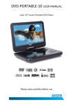
121812-511351
User's Manual
© 2012 All rights reserved
For the most recent version of this manual please visit
http://www.primera.com/manuals.html
Notices: The information in this document is subject to change without notice. NO
WARRANTY OF ANY KIND IS MADE WITH REGARD TO THIS MATERIAL,
INCLUDING, BUT NOT LIMITED TO, THE IMPLIED WARRANTIES OF
MERCHANTABILITY AND FITNESS FOR A PARTICULAR PURPOSE. No liability is
assumed for errors contained herein or for incidental or consequential damages in
connection with the furnishing, performance, or use of this material. This document
contains proprietary information that is protected by copyright. All rights are reserved.
No part of this document may be photocopied, reproduced, or translated into another
language without prior written consent.
Trademark Acknowledgments: Primera is trademark of Primera Technology Inc.
Windows is a registered trademark of Microsoft Corporation. All other trademarks are the
property of their respective owners.
Safety Standard: The DL500 complies with the following safety standard: International
Standard IEC 60825-1, Second Edition, 2007/03
Printing History: Edition 1.0, #511351, Copyright 2012, All rights reserved.
FCC Compliance Statement: This device complies with part 15 of the FCC rules.
Operation is subject to the following two conditions: (1) this device may not cause
harmful interference, and (2) this device must accept any interference received, including
interference that may cause undesired operation.
For Users in the United States: This product is intended to be supplied by a UL listed
Direct Plug-In Power Supply marked "Class 2"or a UL listed ITE Power Supply marked
"LPS" with output rated 12VCD, 5.0 amps or higher. This equipment has been tested and
found to comply with the limits for a Class A digital device, pursuant to Part 15 of the
FCC Rules. In a domestic environment this product may cause radio interference, in
which case the user may be required to take adequate measures. This equipment
generates, uses, and can radiate radio frequency energy and, if not installed and used in
accordance with the instructions, may cause harmful interference to radio
communications. However, there is no guarantee that interference will not occur in a
particular installation. If this equipment does cause harmful interference to radio or
television reception, which can be determined by turning the equipment off and on, the
user is encouraged to try to correct the interference by one or more of the following
measures:
•
•
•
•
Re-orient or relocate the receiving antenna.
Increase the separation between the equipment and receiver.
Connect the equipment into an outlet on a circuit different from that to which the
receiver is connected.
Consult the dealer or an experienced radio/TV technician for help.
Use of shielded cables is required to comply with the Class A limits of Part 15 of the FCC
Rules. You are cautioned that any changes or modifications not expressly approved in this
manual could void your authority to operate and/or obtain warranty service for this
equipment.
For Users in Canada: This digital apparatus does not exceed the Class A limits for
radio noise for digital apparatus set out on the Radio Interference Regulations of the
Canadian Department of Communications. Le present appareil numerique n'emet pas de
bruits radioelectriquesdepassant les limites applicables aux appareils numeriques de la
class A prescrites dans le Reglement sur le brouillage radioelectrique edicte par le
ministere des Communications du Canada.
ii
Table of Contents
Section 1: Important Safety Information ..................................................1
Section 2: Getting Started.............................................................................3
A. Choosing a Good Location ............................................................3
B. Unpacking and Inspection.............................................................3
C. Indentifying the Parts .....................................................................5
D. Computer Specifications ................................................................7
Section 3: Label Stock ...................................................................................8
A. Label and Roll Specifications ........................................................8
B. Installing Label Stock ...................................................................11
Section 4: Setup Your Label and Print .....................................................16
A. Using BarTender® .........................................................................16
B. Add Text, Barcodes and Graphics to a BarTender Label .........22
C. Printing from BarTender ..............................................................23
D. Printing from Other Programs ....................................................24
E. Printer Settings ..............................................................................25
Section 5: Setup the DF-30 Filtration System .........................................30
Section 6: Maintenance and Troubleshooting ........................................32
A. Replacing the Exhaust Duct and Exhaust Chimney................32
B. Cleaning the Laser Windows ......................................................38
C. Cleaning the Feed Path.................................................................39
D. Cleaning the Guide Shafts and Encoder Strip ..........................40
E. Troubleshooting.............................................................................41
). Technical Support ..........................................................................42
Section 7: Specifications .............................................................................43
iii
Interactive.qxd
9/6/2005
3:30 PM
Page 1
Interactive Feature
in this PDF Document
There are interactive features that will allow you to jump
to different locations within the document. Each listing in
the Table of Contents is interactive. Place the cursor on
either the words or the page number. A small hand with a
pointing finger icon appears. Click on the line with the
icon and the document will jump to that page. If you want
to return to the Table of Contents, move to the icon at the
top of the page and click on the arrow marked TOC.
TOC
Section 1: Important Safety Information
Thank you for purchasing the DL500 Durable Label Printer. Please read the
following important safety information before operating your DL500.
CLASS 1 LASER PRODUCT
IEC 60825-1 Second Edition, 2007/03
WARNINGS
•
Use of controls, adjustments or performance of procedures other than
those specified herein may result in hazardous radiation
exposure.
•
Do not attempt to operate the DL500 with the Top Cover open. To
prevent injury, the internal laser will switch off as soon as the Top Cover
is opened.
•
Do not attempt to defeat the cover sensor which triggers the automatic
switch off of the internal laser. Serious eye injury can occur.
•
Do not modify the DL500 in any way or operate the printer with any
damaged components, including the Safety Skirt.
•
Do not attempt to clean any of the Laser Windows while the power is
turned on.
•
Do not attempt to print to smoke or smokeless label stock without the
exhaust system in place.
•
Do not attempt to print without the DF-30 Filtration System when using
label stock which requires the use of the DF-30 Filtration System.
Hazardous smoke and fumes will be released.
•
When using the DF-30 Filtration System make sure the feet on the DL500
are resting inside the indentations on the top of the DF-30.
•
When replacing the exhaust system, switch off power to the unit.
•
To prevent fire or shock hazard, do not expose the unit to rain or
moisture. To reduce the risk of electric shock, do not remove exterior
panels. No user-serviceable parts are inside. Refer to qualified service
personnel.
•
Operate the unit with only proper electrical specifications as labeled on
the unit and the AC adapter.
•
There should be no exposed adhesive on the liner of die-cut labels. It will
cause labels to stick to each other and cause adhesive build-up along the
printer path inside the printer. This adhesive can not easily be cleaned
without disassembling the printer.
Important Safety Information 1
TOC
Safety Labels
Safety labels are affixed to the printer in the following locations:
WARNING: Class 4 invisible laser radiation with
cover open and interlocks defeated. Avoid eye or
skin exposure to direct or scattered radiation.
WARNING: Sharp edge, keep fingers and other body parts away.
Serial Number and ID information
2 Important Safety Information
TOC
Section 2: Getting Started
A. CHOOSING A GOOD LOCATION
•
•
•
•
Place the printer on a flat surface in a location with
adequate air circulation to prevent internal heat build-up.
Do not place the printer near heat sources such as radiators
or air ducts, or in a place subject to direct sun light,
excessive dust, mechanical vibration or shock.
Allow for adequate clearance in front of the printer to
accommodate the printed label stock as it is leaving the
printer to avoid the possibility of binding or jamming of
the label stock.
Allow for adequate overhead and left side clearance for
opening the top cover to allow easy access to the label
stock and maintenance items. The printer will require
9.5 inches (24 cm) of additional space on the left side to
completely open the cover (total = 26.75 inches or 68 cm).
The printer will require an additional 15.9 inches (40.4 cm)
of overhead space to open the cover (total = 25 inches or
63.5 cm).
B. UNPACKING AND INSPECTION
While unpacking your printer, inspect the carton to ensure that
no damage has occurred during shipping. Make sure that all
supplied accessories are included with your unit. The
following items are included in the supply box:
•
•
•
•
•
•
Power Adapter
Separate Power Cord
USB Cable
Software Installer CD
Warranty Statement and Registration Card
This User's Manual and other printed information
Getting Started 3
TOC
The following items are inside the printer supply roll area:
•
Starter Roll of smokeless label stock
Save the carton and packing materials. They will come in handy
when transporting the printer.
4 Getting Started
TOC
C. IDENTIFYING THE PARTS
Front View
Top Cover
Pause LED
Pause Button
Power LED
Load/Feed
Button
Media LED
Label Tear Bar
Unload Button
The Pause Button pauses the printer during a print job. If
pressed when no print job is printing, it will prevent any new
jobs from beginning.
The Power LED indicates that the printer is on and ready to
receive print jobs.
The Load/Feed Button is pressed in order to load label stock if
the printer does not automatically detect the stock. When stock
is loaded each press of the button will cause one label to be fed
from the printer.
The Media LED will illuminate when label stock is installed
and detected. It will flash in a specific sequence for error
conditions. See Section 6E for details.
The Unload Button will unload the installed label stock by
reversing it through the printer. Make sure to tear off the
printed labels before pressing the Unload Button.
The Label Tear Bar is a serrated edge for conveniently tearing
your finished labels from the printer. The printer comes with a
white tear bar guard. For smoother label feeding, leave the
guard in place during printing. When you are ready to tear off
a label, remove the guard, tear off the label and replace it.
Getting Started 5
TOC
Rear View
USB Port
Power Input Port
Power Switch
Filtration Unit
Communication Port
(9-pin serial)
Interior View, Label Roll Area
Fixed Label Stock Hub
Data Chip Contact
Label Stock Hub Supports
6 Getting Started
Moveable Label Stock Hub
Hub Engagement Lever
TOC
Interior View, Carrier
Carrier
Label Feed Exit Area
Exhaust Duct
Laser Windows
DO NOT TOUCH
Safety Skirt
WARNING
Invisible Laser Path
DO NOT BLOCK
E. COMPUTER SPECIFICATIONS
For optimal printing speed you must have a PC with the
following recommended specifications:
•
•
•
•
Pentium Dual Core Processor
2 GB of RAM
10 GB of free hard drive space
Windows XP, Vista, 7 or 8
Getting Started 7
TOC
Section 3: Label Stock
A. LABEL AND ROLL SPECIFICATIONS
Important Notes Regarding Label Stock
•
•
•
•
The DL500 can only be used with label stock manufactured
or approved by Primera. Several standard sizes are
available. Custom sizes can also be ordered. This printer
requires a custom plastic hub with an integrated data chip.
Both smoke and smokeless label types are available. Smoke
labels require the use of an optional filtration system and
the replacement of exhaust ducting. (See Section 5 and 6A.)
Every label core contains a data chip which records the
type of label stock, the required laser power, the required
sensor type and the number of labels on the roll. When
the label stock is inserted in the printer, the laser power
and sensor type are automatically set. If the stock requires
a DF-30 filtration system, the printer will attempt to detect
if the DF-30 is connected via the 9-pin serial port. If the
filtration unit is not connected, the printer will not print.
Various under layer and top layer colors are available to
produce different colored text, graphics and barcodes.
8 Label Stock
TOC
Label Sensing Methods
Label Width
Liner Width
Gap Between
Labels
Method 1: Label
Gap Sensing
Distance from
Edge of Liner
Width of Thru-Hole
Method 2: Thru-Hole
Sensing
Distance from
edge of Liner
to edge of Label
Label Height
Method 3: Reflective Sensing
(Black mark must be printed on
back side of label stock.)
Label widths smaller
than 1.5” will need to
be justified on the liner
to trigger both the
infeed and TOF sensor.
Black Mark
Width
Infeed Sensor Path
(factory set at 1.4”)
TOF Sensor Path
(fixed at 1”)
Note:
See table below for Max and Min values in inches and mm.
Label Stock 9
TOC
Max
Min
Label Width
5.125" (130 mm) 0.75" (19 mm)
Liner Width
5.125" (130 mm) 1.5" (38.1 mm)
Label Height/Length
12" (305 mm)
0.75" (19 mm)
Gap between labels
10" (253 mm)
0.1" (2.5 mm)
Width of Thru-Hole
2" (50.8 mm)
0.6" (15.2 mm)
Distance from Edge of
Liner to Edge of
Thru-Hole
0.9" (22.9 mm)
0.5" (12.7 mm)
Reflective Sensing/Black
Mark Width*
N/A
0.1" (2.5 mm)
Max Outer Diameter (OD) 6.0" (152.4 mm)
N/A
Inner Core Diameter (ID)
3.0" (76.2 mm)
3.0" (76.2 mm)
Total Thickness
(Liner + Label)**
0.0075”
(7.5 mil)
N/A
Distance from Edge of
Media to Edge of Label
Printer driver assumes .063" (1.6 mm)
gap. However, this is adjustable
via the Left Margin Offset setting.
* The black mark should be opaque to infared light. The mark
should be between the labels. The end of the mark should
correspond with the beginning of the label.
**There are two factors that determine whether the printer will
accept any particular stock thickness.
1.
The ability for the printer to pull the paper through the
print area.
2.
The ability for the sensor to read through the liner if the
sensor is set to die cut.
If you are printing in continuous or reflective label sensing
mode, Number 2 does not apply. The fact that the printer must
read through the backing in die-cut mode will limit the
thickness much more than the printer's ability to pull the paper
through the print area. However, if you adjust the opacity level
of the liner enough to allow the label to be seen by the stock
sensor, the thickness will only be limited by the printer's ability
to pull it through the print area. For these reasons the weight
or thickness of the liner is a variable that can not easily be
recommended.
10 Label Stock
TOC
B. INSTALLING LABEL STOCK
The following steps will guide you through loading label stock
in your printer.
1.
Open the Top Cover.
Lift Here
here.
Lift
2.
Find the label stock roll area near the back of the printer.
Label Stock 11
TOC
3.
Pull the Hub Engagement Lever down until it locks into
position.
Hub Engagement Lever
4.
Locate the label stock roll. Remove the foam shipping
spacer. Place the roll on the Hub Supports. Stock should be
installed with the labels facing up and coming off the top of
the roll.
Foam Spacer
Hub Supports
12 Label Stock
TOC
5.
Pull the Hub Engagement Lever up. The moveable hub
will engage the label stock hub.
6.
Pull the Movable Throat Guide outward to make room for
the label stock.
Moveable Throat Guide
Fixed Throat Guide
Label Stock 13
TOC
7.
Place the leading edge of the label stock under the "label
stock" symbols on the Throat Guides. The label stock
should be placed far enough into the throat of the printer
to correctly position the Movable Throat Guide but not
fully into the print mechanism.
8.
Slide the Movable Throat Guide inward until it almost
touches the label stock.
DO NOT PINCH
14 Label Stock
TOC
Caution: The gap between the Throat Guides should be narrow enough to
accurately guide the label stock but not narrow enough to pinch the
label stock. (The gap should be .016" - .032" [0.4 - .08mm] wider
than the label stock.) If the label stock is pinched by the guides, poor
print quality or feeding problems could result.
9.
Feed the label stock further into the printer until it senses
the label and automatically feeds it through the printer.
Caution: There should be no exposed adhesive at the edges of die-cut labels. It
will cause labels to stick to each other and cause adhesive build-up
along the printer path inside the printer. This adhesive can not easily
be cleaned without disassembling the printer. Do not feed label stock
into the printer that seems to stick to itself as it is unwound from the
roll!
Note:
If the printer fails to feed the label stock, press the Load/Feed button
on the front panel while continuing to guide the label stock into the
printer. If the printer still does not feed or skips labels, check the
in-feed sensor position. It should be set to 1.4". Do not move it from
this position unless directed by Primera Technical Support!
2.5
[63.5]
2.0
[50.8]
1.5
[38.1]
1.0
[25.4]
0.5
[12.7]
0.0
[0.0]
in.
[mm]
Label Stock 15
TOC
Section 4: Setup Your Label and Print
A. USING BARTENDER®
BarTender PE is included with the DL500. Other programs can
be used to print. If printing from other programs please follow
the guidelines in Section 4C.
When you open BarTender you will be given the choice to
select an existing label or create a new one using a wizard. Use
the following instructions as a guide through the wizard setup
process.
1.
Choose "Start a new label format. . ."
16 Setup Your Label and Print
TOC
2.
Select "Blank Label Format". Click "Next".
3.
Select "Durable Label 500". Click "Next".
Setup Your Label and Print 17
TOC
4.
Select "Specify Custom Settings". Click "Next".
5.
Set the page size, width and height to match labels
installed in the printer. Click "Next".
18 Setup Your Label and Print
TOC
6.
Set your shape. Typically you would choose "Rounded
Rectangle". Most labels have a .125” corner radius which is
automatically set when you choose "Rounded Rectangle".
If your labels have square corners, set your shape to
"Rectangle". Click "Next".
7.
Set all of your margins to zero. Click "Next".
Setup Your Label and Print 19
TOC
8.
Set both rows and columns to "1". Click "Next" or "Finish".
If you click "Finish", the remaining default wizard options
will be set.
9.
The label size is automatically set the same as the page
size. No changes are necessary. Click "Next" or "Finish".
If you click "Finish", the remaining default wizard options
will be set.
20 Setup Your Label and Print
TOC
10. Set your background photo, if desired. For this printer
you will probably not want a background photo. In this
case, select "None". Click "Next" or "Finish". If you click
"Finish", the remaining default wizard options will be set.
11. Review the label setup summary. If it is correct, click
"Finish". Your blank label will be displayed.
You can edit any of these settings by going to the File Menu
and selecting "Page Setup". Basic and advanced settings are
available on the various tabs.
Setup Your Label and Print 21
TOC
B. ADD TEXT, BARCODES AND GRAPHICS TO A
BARTENDER LABEL
Once you have created your label size you will need to add
text, a barcode and/or graphics. This can be done using one of
buttons on the button bar at the top of the screen.
Add Text. Click the Text button.
Add Graphic. Click the Image
Add Barcode. Click the Barcode
button. Now click anywhere on
your label. A barcode settings
window will appear. Here you can
chose any type of barcode and enter
the value.
Print. Click the Print button to
Page Setup. Click the Page Setup
button to change your label size,
adjust corner radius or change the
shape.
Lines. Click the Line button to
add a horizontal or vertical line.
Now click anywhere on your label.
"Sample Text" will appear. Edit the
text on screen or double click it to
open up text settings to change
font, size and other settings.
button. Now click anywhere on
your label. An Image icon will
appear. Double-click it to open
up image settings and browse to
the image/graphic that you
would like to insert.
start printing.
Tip! Double-click any object to open settings for that object.
22 Setup Your Label and Print
TOC
C. PRINTING FROM BARTENDER
1.
To print, click the Print button
or go to the File
Menu and select "Print". The Print Dialog window will
appear.
2.
Select the Durable Label 500.
3.
Set the number of copies.
4.
Click "Print".
Setup Your Label and Print 23
TOC
D. PRINTING FROM OTHER PROGRAMS
Since this printer uses a standard Windows printer driver you
can print from any application you would like. There are just a
few things to remember that will make it much easier.
1.
Set the Page/Label Size in the driver. BarTender
automatically prompts you for the size of the label that
you are using. When printing from any other program
you must do this manually. Before you print, simply set
the custom page size just as you would set print quality in
the printing preferences.
2.
Check the image or document size. The image size or
document size should correspond to the Page/Label Size
set in the driver. If you have set your page size to 4" x 4",
but your image is actually 5" x 3", the printer driver will
automatically shrink your image to fit inside the 4" x 4"
label. The result is that the actual printed label is 4" x 2.4".
Avoid this by setting your page size or image size to match
the label size.
3.
Choose the right printing program. There are many
different applications that are capable of printing to the
DL500. However, there are only a few that are ideal
printing applications. For example, Adobe Illustrator is
an excellent design program but is not always the best
printing program. It can be difficult to find the printing
preferences or to know the exact size of the art board. It is
best to save as a PDF file and print from Adobe Reader or
export a 300 dpi JPG and print from BarTender.
24 Setup Your Label and Print
TOC
E. PRINTER SETTINGS
To access basic settings such as Paper Size and Orientation go
to the Start Menu – Choose Devices and Printers (Printers and
Faxes for Windows XP) – Select the Durable Label 500. Right
click on it and choose "Printing Preferences". You may also
access these settings from the print window of any printing
program.
To access advanced printer settings go to the Start Menu.
Choose "All Programs". Then choose "DL500 Settings".
Current status of the printer will be displayed on the bottom of
the application along with the remaining number of labels on
the installed roll and the total number of labels printed over
the life of your printer.
Setup Your Label and Print 25
TOC
There are four tabs across the top. The following is a
description of the contents of each.
Status Tab
The Status tab contains the current status of the printer and
details about any error that appears.
You can also switch to Advanced mode which displays
additional status which may be useful to tech support for
solving any problems.
Offsets Tab
If text, graphics, or barcodes are not printing centered on the
label or they are printing partially off the label you can adjust
the offsets using the Offsets tab.
Top of Form (TOF) – Adjust this setting to move the printed
image vertically on the label.
Left Margin Offset – Adjust this setting to move the printed
image horizontally on the label.
26 Setup Your Label and Print
TOC
Tear Off Position – When using the Present mode, adjust this
setting to change the output position of the label. This will
move the labels out further from the printer or move them
back toward the printer. The goal is to center the gap between
labels over the Label Tear Bar so that you can easily tear off a
run of labels after they have been printed.
Media Settings Tab
You can adjust Output Mode settings and media overrides. All
media comes with an internal memory chip which stores the
correct settings for that media. The printer uses those settings
to print to the media. However, using the media overrides,
you can change the settings.
Output Mode – Using this setting you can adjust how the
printed label will be presented.
•
•
•
Set to "Present Each Label" if you will only be printing one
label at a time and then tearing off that label. You must
press the Pause button to eject the printed label.
Set to "Present After No Activity" if you will be printing
more than one label.
Set to "Do Not Present" if you will be rewinding labels onto
a core using another device.
Setup Your Label and Print 27
TOC
Media Overrides – Media chip values are the settings stored on
the media chip inside the label core. Override values can be
set to override Default values.
•
•
•
•
•
Sensor Type should not be adjusted unless the stock has
been modified after purchase.
Max Laser Power, Laser On Time and 2-Pass can all be
adjusted to improve print quality.
Print Speed can be decreased to improve quality and/or
decrease the noise level of the printer.
Use Vacuum can be used to switch on the filtration unit if
label media default is set to off. You cannot uncheck the
Use Vacuum setting if the label stock default requires the
use of the filtration unit.
Clear Overrides will revert all settings to defaults stored
on the Media chip.
28 Setup Your Label and Print
TOC
Preferences Tab
On the Preferences tab you can adjust how the status bar at the
bottom of the settings application displays the media
remaining on the roll.
By default the settings application will show the remaining
media in inches or cm depending on how you set the Display
Units on this tab. However, you can set the software to display
labels remaining. You will need to measure the actual label
height and the gap between each label and enter them on this
tab. Check "Show Remaining as Labels" to enable label
tracking.
Information Icon
Click the information icon in the upper right corner of the
software to display software version information.
Setup Your Label and Print 29
TOC
Section 5: Setup the DF-30 Filtration
System
Smoke labels require the use of an optional filtration system
(DF-30) and the replacement of exhaust ducting.
Every label core contains a data chip which records the type of
label stock. If the stock requires a DF-30 filtration system, the
printer will attempt to detect if the DF-30 is connected via the
9-pin serial port. If the filtration unit is not connected, the
printer will not print.
Follow these instructions to connect the DF-30:
1.
Disconnect power and USB if it is connected to the DL500.
2.
Lift the DL500 onto the top of the DF-30. Make sure that
the feet on the DL500 are resting in the indents on the top
of the DF-30. This will insure a sealed connection between
the gasket on the top of the DF-30 and the bottom vent on
the DL500.
Vent
Indent
Indent
Air Intake Diverter
30 Setup the DF-30 Filtration System
Gasket
TOC
3.
Now connect the Serial Cable to the back of the DL500 and
the side of the DF-30.
Serial Port
Power Port
DF-30
Power Button
FILTRATION SYSTEM
System ON
RESET
POWER
Service Motor
Service Filters
POWER
CORD
CALIBRATION
Remote / Standby
REMOTE CONTROL
www.primeralabel.com
Warning: Disconnect power cord from wall outlet prior to opening doors and/or servicing unit.
4.
Connect power to the DF-30 and switch it on.
5.
Connect power and USB to the DL500.
Note:
The DL500 will automatically turn on the fan and regulate the air
flow on the DF-30.
Note:
The DF-30 will require periodic filter replacement. Replace filters
according to the DF-30 User's Manual when the Service Filters LED
is illuminated.
Setup the DF-30 Filtration System 31
TOC
Section 6: Maintenance and
Troubleshooting
The follow maintenance should be done according to the
schedule below:
Maintenance Action
Frequency
Section
Clean Guide Shafts
Before every
label roll*
6D
Clean Encoder Strip
Every five label
rolls*
6D
Replace Exhaust System
Before every
label roll
6A
Clean Print Support Plate Before every smoke
label roll
6A (Step 4)
Clean Exhaust Duct
(bottom edges)
As needed for
smokeless labels
6C
Clean Laser Windows
As needed
(inspect regularly)
6B
* During the break-in period you will see more debris on these
components which may require more frequent cleaning. Over
time the amount of debris will diminish and so will the need to
clean these components.
A. REPLACING THE EXHAUST DUCT AND EXHAUST
CHIMNEY.
If smoke labels are used, the Exhaust Duct and Exhaust
Chimney will need periodic replacement.
Replace the exhaust system every time you change to a new
roll of smoke label stock!
You may also need to replace the exhaust system if poor print
quality occurs. If text or graphics are no longer sharp or
missing entirely, it is possible the glass on the Exhaust Duct has
become clouded. If duct replacement is necessary more than
once during a single roll, the filtration system may not be
working properly.
32 Maintenance and Troubleshooting
TOC
Note:
Smoke labels require the use of the DF-30 Filtration System.
Note:
A replacement Exhaust Duct and Exhaust Chimney come with
every new roll of smoke label stock. You can also purchase additional
replacements from Primera.
Exhaust Duct
(Part # 084001)
Exhaust Chimney
(Part # 084002)
Replacing the Exhaust System
1.
Unplug power to the printer!
Lift here.
Lift
Here
2.
Open the cover.
Maintenance and Troubleshooting 33
TOC
3.
Move the Carrier to the far left if it is not already there. Pull
the right side of the Exhaust Duct up and through the slot
as shown in the illustration. Then slide the duct to the right
to completely remove it.
Carrier
2
3
Exhaust Duct
1
34 Maintenance and Troubleshooting
TOC
4.
Once the Exhaust Duct has been removed you will have
access to the label feed path. Inspect the area for smoke
residue. Remove it using rubbing alcohol and a paper
towel or cloth. Smoke residue will be present on the Print
Support Plate where it was not covered by label stock.
Clean with Isopropyl Alcohol
Exhaust Chimney
5.
Remove the Exhaust Chimney by grasping it as shown in
the illustration and pulling up.
6.
Discard the used exhaust system.
Maintenance and Troubleshooting 35
TOC
7.
Locate a new Exhaust Chimney. Insert the new Exhaust
Chimney with the gasket end down. Push it down until
the top is even with the adjacent Print Support Plate.
Gasket
8.
Locate a new Exhaust Duct. After making sure the carrier
is pushed to the far left, insert the left side into the slot as
shown in the illustration.
Carrier
Slot
36 Maintenance and Troubleshooting
Exhaust Duct
TOC
9.
Guide the right end of the duct down through the slot as
shown in the illustration. Push toward the rear of the
printer until the duct snaps into place. Verify that the
opening in the bottom of the Exhaust Duct aligns with the
top of the Exhaust Chimney.
Print Head
2
1
Exhaust Duct
3
Maintenance and Troubleshooting 37
TOC
B. CLEANING THE LASER WINDOWS
Cleaning the Laser Windows is necessary if debris, dust, finger
prints or smoke residue are visible on the windows. Typically,
poor print quality would be the first sign of Laser Window
contamination.
Carrier
Laser Windows
To clean the windows, first disconnect power. Then use a soft,
dry cloth to wipe away the contamination. If there is smoke
residue you may need to use a small amount of isopropyl
(rubbing) alcohol to remove the debris.
Note:
To clean the Laser Window on the Carrier you may need to use a
cotton swab to reach it. The cloth or cotton swab should not be
saturated with alcohol.
Laser Window
38 Maintenance and Troubleshooting
TOC
C. CLEANING THE FEED PATH
If smokeless label stock is used the exhaust system will not
need to be replaced every roll of label stock. However, this
means that adhesive may build up on the bottom edge of the
Exhaust Duct. To clean the Exhaust Duct and feed path use the
following instructions:
1.
Remove the Exhaust Duct according to the instructions in
Section 6A.
2.
Inspect the underside of the Exhaust Duct. Remove any
adhesive with a petroleum-based cleaner such as WD40™
or Goo Gone™.
3.
Also inspect the feed area inside the printer. Clean any
adhesive from this area. If it has accumulated on the
Exhaust Duct, excess adhesive may have been deposited
along the edges of the label feed path.
Feed Path
4.
Check for adhesives build
up along the edges.
When you are finished, replace the Exhaust Duct.
Maintenance and Troubleshooting 39
TOC
D. CLEANING THE GUIDE SHAFTS AND ENCODER STRIP
The Guide Shafts and the Encoder Strip should be inspected
regularly for debris and then cleaned, if necessary. The Guide
Shafts are the metal bars upon which the Carrier travels. The
Encoder Strip is a transparent strip of plastic with small
vertical lines. The Carrier counts the lines to determine where
it is on the Guide Shafts.
If the Guide Shafts are dirty, the smooth motion of the Carrier
could be affected. This can cause print quality issues. If the
Encoder Strip becomes dirty, the Carrier can have a difficult
time determining where to start/stop printing. This will cause
the printing to be located improperly on the label.
Cleaning the Upper and Lower Guide Shafts. With a soft
cloth soaked with isopropyl (rubbing) alcohol, scrub the Guide
Shafts clean. It is important to clean all surfaces in contact with
the Carrier Wheels.
Cleaning the encoder strip. With a soft cloth soaked with
isopropyl (rubbing) alcohol, pinch the Encoder Strip with the
cloth. Gently move the cloth back and forth along the Encoder
Strip. Move the carrier out of the way to reach the entire
length of the Encoder Strip. Carefully visually verify that no
debris remains on the Encoder Strip.
Warning:
Disconnect
power before
attempting
any cleaning
procedures.
Upper Guide Shaft
Lower Guide Shaft
40 Maintenance and Troubleshooting
Encoder Strip
TOC
E. TROUBLESHOOTING
Print quality is poor; missing
or blurry text, graphics or
barcodes.
1. Replace the exhaust system
according to Section 6A.
2. Clean the Laser Windows
according to Section 6B.
3. Clean the Guide Shafts or
Encoder Strip according to
Section 6D.
Printer is not printing.
1. Make sure the printer is
turned on.
2. Make sure the power cord
is connected.
3. Make sure the USB cable
is connected.
4. Make sure DF-30 is
connected and turned on, if
using smoke label stock.
5. Make sure label stock is
loaded.
Interpreting the Printer’s Indicator Lights.
Power LED solid,
Media LED solid
Labels are installed and
Printer is ready for printing.
Media LED blinking
Label stock is low.
Media LED is flashing
slowly
Label roll is installed, but label
stock is not loaded.
Media LED is flashing
quickly
Label roll is installed, but empty.
Media LED is off
Label roll is not installed.
Power, Media, Pause
LEDs alternating
Printer is starting up or resetting.
Maintenance and Troubleshooting 41
TOC
F. TECHNICAL SUPPORT
If you have difficulties in operating your printer, the
procedures in this manual and the software User's Guide
should, in most cases, solve the problem. If you still have
difficulty, contact the technical support number using one of
the methods listed below.
Source
Location
Primera Knowledge Base
www.primera.com/knowledgebase.html
BarTender Software Help files
Open the software. Click on the Help
Menu - Contents
Email Support
www.primera.com/contact_tech_support.cfm
Chat Support
www.primera.com/knowledgebase.html
Phone Support
763-475-6669 (Mon - Fri, 8 am - 6 pm CST)
42 Maintenance and Troubleshooting
TOC
Section 7: Specifications
Print Method:
Print Resolution:
Max. Print Width:
Max. Substrate Width:
Media Types:
Laser ablation
300 dpi
5.125” (130 mm)
5.125” (130 mm)
Smoke and smokeless laser-marking
films
Media Sensing:
See-through and black mark reflective
sensors
Supply Roll:
6” (152 mm) OD on 3” (76.2 mm)
ID core
Label Design Software: BarTender Primera Edition included
(Most other Windows-based label
design software may also be used)
Operating System:
Windows XP/Vista/7/8
Data Interface:
USB 2.0
Indicator Lights:
Power, Pause, Media
Electrical Rating:
12 VDC, 5.0 amps
Power Requirements:
100-240 VAC, 50/60 Hz
Agency Approvals:
UL, UL-C, CE, FCC Class A
Laser Safety Certification: CDRH and IEC 60825-1 Ed. 2, 2007/03
Laser Wavelength
980 nm
Laser Beam Divergence 17 degrees
Laser Maximum Power 10 watts
Weight:
37.5 lbs (17 kg)
Dimensions:
17.25” W x 9.1” H x 17.25” D
(438 mm W x 231 mm H x 438 mm D)
Options:
DF-30 Filtration System
Data Interface:
9-pin serial
Specifications 43
Printed in the United States of America
P/N 511351