1
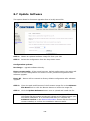
VR-3030
Multi-DSL Router
User Manual
Version A1.0, May 28, 2013
261099-016
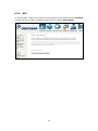
Preface
This manual provides information related to the installation and operation of this
device. The individual reading this manual is presumed to have a basic
understanding of telecommunications terminology and concepts.
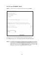
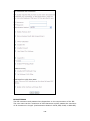
Important Safety Instructions
With reference to unpacking, installation, use, and maintenance of your electronic
device, the following basic guidelines are recommended:
•
•
•
•
•
•
Do not use or install this product near water, to avoid fire or shock hazard. For
example, near a bathtub, kitchen sink or laundry tub, or near a swimming pool.
Also, do not expose the equipment to rain or damp areas (e.g. a wet basement).
Do not connect the power supply cord on elevated surfaces. Allow it to lie freely.
There should be no obstructions in its path and no heavy items should be placed
on the cord. In addition, do not walk on, step on, or mistreat the cord.
Use only the power cord and adapter that are shipped with this device.
To safeguard the equipment against overheating, make sure that all openings in
the unit that offer exposure to air are not blocked.
Avoid using a telephone (other than a cordless type) during an electrical storm.
There may be a remote risk of electric shock from lightening. Also, do not use
the telephone to report a gas leak in the vicinity of the leak.
Never install telephone wiring during stormy weather conditions.
CAUTION:
To reduce the risk of fire, use only No. 26 AWG or larger
telecommunication line cord.
Always disconnect all telephone lines from the wall outlet before servicing
or disassembling this equipment.
WARNING
Disconnect the power line from the device before servicing.
Power supply specifications are clearly stated in Appendix C Specifications.
1
Copyright
Copyright©2013 Comtrend Corporation. All rights reserved. The information
contained herein is proprietary to Comtrend Corporation. No part of this document
may be translated, transcribed, reproduced, in any form, or by any means without
prior written consent of Comtrend Corporation.
This program is free software: you can redistribute it and/or modify it under the
terms of the GNU General Public License as published by the Free Software
Foundation, either version 3 of the License, or (at your option) any later version.
This program is distributed in the hope that it will be useful, but WITHOUT ANY
WARRANTY; without even the implied warranty of MERCHANTABILITY or FITNESS
FOR A PARTICULAR PURPOSE. See the GNU General Public License for more
details.
You should have received a copy of the GNU General Public License
along with this program. If not, see http://www.gnu.org/licenses/
NOTE:
This document is subject to change without notice.
Protect Our Environment
This symbol indicates that when the equipment has reached the end of
its useful life, it must be taken to a recycling centre and processed
separate from domestic waste.
The cardboard box, the plastic contained in the packaging, and the parts that make
up this router can be recycled in accordance with regionally established regulations.
Never dispose of this electronic equipment along with your household waste; you
may be subject to penalties or sanctions under the law. Instead, please be
responsible and ask for disposal instructions from your local government.
2
Table of Contents
CHAPTER 1 INTRODUCTION ........................................................................................................... 5
CHAPTER 2 INSTALLATION............................................................................................................. 6
2.1 HARDWARE SETUP ........................................................................................................................... 6
2.2 LED INDICATORS............................................................................................................................. 8
CHAPTER 3 WEB USER INTERFACE.............................................................................................. 9
3.1 DEFAULT SETTINGS ......................................................................................................................... 9
3.2 IP CONFIGURATION ........................................................................................................................ 10
3.3 LOGIN PROCEDURE........................................................................................................................ 12
CHAPTER 4 DEVICE INFORMATION ........................................................................................... 14
4.1 WAN ............................................................................................................................................. 15
4.2 STATISTICS ..................................................................................................................................... 16
4.2.1 LAN Statistics .................................................................................................................... 16
4.2.2 WAN Service ...................................................................................................................... 17
4.2.3 XTM Statistics ................................................................................................................... 18
4.2.4 xDSL Statistics .................................................................................................................. 19
4.3 ROUTE ........................................................................................................................................... 24
4.4 ARP............................................................................................................................................... 25
4.5 DHCP............................................................................................................................................ 25
4.6 NAT SESSION ................................................................................................................................ 27
4.7 IGMP PROXY ................................................................................................................................ 28
4.8 IPV6 .............................................................................................................................................. 29
4.8.1 IPv6 Info ................................................................................................................................ 29
4.8.2 IPv6 Neighbor ....................................................................................................................... 30
4.8.3 IPv6 Route ............................................................................................................................. 31
4.8.4 Network Map ......................................................................................................................... 31
CHAPTER 5 BASIC SETUP............................................................................................................... 32
5.1 LAYER 2 INTERFACE ...................................................................................................................... 32
5.1.1 WAN Service Setup ................................................................................................................ 33
5.2 NAT .............................................................................................................................................. 34
5.2.1 Virtual Servers................................................................................................................... 34
5.2.2 Port Triggering ................................................................................................................. 35
5.2.3 DMZ Host.......................................................................................................................... 37
5.2.4 IP Address Map .................................................................................................................. 38
5.2.5 IPSEC ALG ......................................................................................................................... 40
5.2.6 SIP ALG .............................................................................................................................. 41
5.3 LAN .............................................................................................................................................. 42
5.3.1 LAN IPv6 Autoconfig ............................................................................................................. 45
5.3.2 Static IP Neighbor ................................................................................................................. 48
5.3.3 UPnP ..................................................................................................................................... 49
CHAPTER 6 ADVANCED SETUP ..................................................................................................... 50
6.1 AUTO-DETECTION SETUP ............................................................................................................... 50
6.2 SECURITY ...................................................................................................................................... 55
6.2.1 IP Filtering ........................................................................................................................ 55
6.2.2 MAC Filtering ................................................................................................................... 58
6.3 PARENTAL CONTROL...................................................................................................................... 60
6.3.1 Time Restriction ................................................................................................................ 60
6.3.2 URL Filter ......................................................................................................................... 62
6.4 QUALITY OF SERVICE (QOS) .......................................................................................................... 64
6.4.1 QoS Queue Setup .............................................................................................................. 65
6.4.2 QoS Policer ....................................................................................................................... 67
6.4.3 QoS Classification .............................................................................................................. 69
6.5 ROUTING ....................................................................................................................................... 72
6.5.1 Default Gateway ............................................................................................................... 72
6.5.2 Static Route ....................................................................................................................... 73
3
6.5.3 Policy Routing ................................................................................................................... 74
6.5.4 RIP .................................................................................................................................... 75
6.6 DNS .............................................................................................................................................. 76
6.6.1 DNS Server........................................................................................................................ 76
6.6.2 Dynamic DNS.................................................................................................................... 77
6.6.3 DNS Entries ...................................................................................................................... 78
6.6.4 DNS Proxy/Relay ................................................................................................................ 79
6.7 DSL............................................................................................................................................... 80
6.8 IP TUNNEL ..................................................................................................................................... 82
6.8.1 IPv6inIPv4 ............................................................................................................................. 82
6.8.2 IPv4inIPv6 ............................................................................................................................. 84
6.9 CERTIFICATE .................................................................................................................................. 85
6.9.1 Local ................................................................................................................................. 85
6.9.2 Trusted CA ........................................................................................................................ 87
6.10 POWER MANAGEMENT ................................................................................................................ 88
6.11 MULTICAST .................................................................................................................................. 89
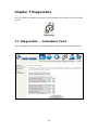
CHAPTER 7 DIAGNOSTICS ............................................................................................................. 91
7.1 DIAGNOSTICS – INDIVIDUAL TESTS ............................................................................................... 91
7.2 FAULT MANAGEMENT.................................................................................................................... 92
7.3 UPTIME STATUS ............................................................................................................................. 93
7.4 PING .............................................................................................................................................. 94
7.5 TRACE ROUTE ............................................................................................................................... 95
7.6 SYSTEM UTILIZATION .................................................................................................................... 96
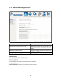
CHAPTER 8 MANAGEMENT .......................................................................................................... 97
8.1 SETTINGS ....................................................................................................................................... 97
8.1.1 Backup Settings ................................................................................................................. 97
8.1.2 Update Settings ................................................................................................................. 98
8.1.3 Restore Default.................................................................................................................. 98
8.2 SYSTEM LOG ................................................................................................................................. 99
8.3 SNMP AGENT ............................................................................................................................. 101
8.4 TR-069 CLIENT ........................................................................................................................... 102
8.5 INTERNET TIME ........................................................................................................................... 104
8.6 ACCESS CONTROL ....................................................................................................................... 105
8.6.1 Passwords ......................................................................................................................... 105
8.6.2 Service Access................................................................................................................... 107
8.6.3 IP Address ......................................................................................................................... 108
8.7 UPDATE SOFTWARE ..................................................................................................................... 109
8.8 REBOOT ....................................................................................................................................... 110
CHAPTER 9 LOGOUT ..................................................................................................................... 111
APPENDIX A - FIREWALL ............................................................................................................. 112
APPENDIX B - PIN ASSIGNMENTS .............................................................................................. 115
APPENDIX C - SPECIFICATIONS ................................................................................................. 116
APPENDIX D - SSH CLIENT .......................................................................................................... 118
APPENDIX E- CONNECTION SETUP .......................................................................................... 119
4
Chapter 1 Introduction
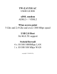
The VR-3030 is an 802.11n compliant Multi-DSL router that supports both
ADSL2+ and VDSL2. The latter is a brand new standard and technology perfect
for triple play (Video, Voice and Data) applications. The VR-3030 comes with one
10/100 Base-T Ethernet port.
The VR-3030 is a cost effective solution designed to meet the needs of ISPs and
carriers planning on deploying a single DSL device for covering end users in different
loop range areas. Deploying VR-3030 is cost effective for ISPs and carriers because
deploying a single CPE DSL device with multiple profile support minimizes the
number of required upgrades.
5
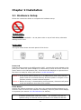
Chapter 2 Installation
2.1 Hardware Setup
Follow the instructions below to complete the hardware setup.
Non-stackable
This device is not stackable – do not place units on top of each other, otherwise
damage could occur.
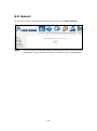
BACK PANEL
The figure below shows the back panel of the device.
Power ON
Press the power button to the OFF position (OUT). Connect the power adapter to the
power port. Attach the power adapter to a wall outlet or other AC source. Press the
power button to the ON position (IN). If the Power LED displays as expected then
the device is ready for setup (see section 2.2 LED Indicators).
Caution 1: If the device fails to power up, or it malfunctions, first verify that the
power cords are connected securely and then power it on again. If the
problem persists, contact technical support.
Caution 2: Before servicing or disassembling this equipment, disconnect all power
cords and telephone lines from their outlets.
Reset Button
Restore the default parameters of the device by pressing the Reset button for 10
seconds. After the device has rebooted successfully, the front panel should display
as expected (see section 2.2 LED Indicators for details).
NOTE:
If pressed down for more than 60 seconds, the VR-3030 will go into a
firmware update state (CFE boot mode). The firmware can then be
updated using an Internet browser pointed to the default IP address.
6
Ethernet (LAN) Port
Use a 10/100 BASE-T RJ-45 cable to connect to a network device. The ports is
auto-sensing MDI/X; so either straight-through or crossover cable can be used.
DSL Port
Connect to an ADSL2/2+ or VDSL with this RJ11 Port. This device contains a micro
filter which removes the analog phone signal. If you wish, you can connect a
regular telephone to the same line by using a POTS splitter.
7
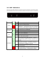
2.2 LED Indicators
The front panel LED indicators are shown below and explained in the following table.
This information can be used to check the status of the device and its connections.
LED
Color
Green
Mode
On
The device is powered up.
Off
The device is powered down.
On
POST (Power On Self Test) failure or other
malfunction. A malfunction is any error of internal
sequence or state that will prevent the device from
connecting to the DSLAM or passing customer data.
On
An Ethernet Link is established.
Off
An Ethernet Link is not established.
Blink
Data transmitting or receiving over LAN.
On
xDSL Link is established.
Off
xDSL Link is not established.
Blink
fast: xDSL Link is training or data transmitting.
slow: xDSL training failed.
On
IP connected and no traffic detected. If an IP or
PPPoE session is dropped due to an idle timeout, the
light will remain green if an ADSL connection is still
present.
Off
Modem power off, modem in bridged mode or ADSL
connection not present. In addition, if an IP or
PPPoE session is dropped for any reason, other than
an idle timeout, the light is turned off.
Blink
IP connected and IP Traffic is passing thru the device
(either direction)
POWER
Red
ETHERNET
DSL
Green
Green
Green
INTERNET
Red
Function
On
Device attempted to become IP connected and failed
(no DHCP response, no PPPoE response, PPPoE
authentication failed, no IP address from IPCP, etc.)
8
Chapter 3 Web User Interface
This section describes how to access the device via the web user interface (WUI)
using an Internet browser such as Internet Explorer (version 5.0 and later).
3.1 Default Settings
The factory default settings of this device are summarized below.
•
•
•
•
•
LAN IP address: 192.168.1.1
LAN subnet mask: 255.255.255.0
Administrative access (username: root, password: 12345)
User access (username: user, password: user)
Remote (WAN) access (username: support, password: support)
Technical Note
During power on, the device initializes all settings to default values. It will then
read the configuration profile from the permanent storage section of flash memory.
The default attributes are overwritten when identical attributes with different values
are configured. The configuration profile in permanent storage can be created via
the web user interface or telnet user interface, or other management protocols.
The factory default configuration can be restored either by pushing the reset button
for more than ten seconds until the power indicates LED blinking or by clicking the
Restore Default Configuration option in the Restore Settings screen.
9
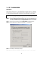
3.2 IP Configuration
DHCP MODE
When the VR-3030 powers up, the onboard DHCP server will switch on. Basically,
the DHCP server issues and reserves IP addresses for LAN devices, such as your PC.
To obtain an IP address from the DCHP server, follow the steps provided below.
NOTE:
The following procedure assumes you are running Windows XP.
However, the general steps involved are similar for most operating
systems (OS). Check your OS support documentation for further details.
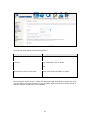
STEP 1: From the Network Connections window, open Local Area Connection (You
may also access this screen by double-clicking the Local Area Connection
icon on your taskbar). Click the Properties button.
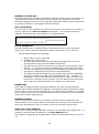
STEP 2: Select Internet Protocol (TCP/IP) and click the Properties button.
STEP 3: Select Obtain an IP address automatically as shown below.
STEP 4: Click OK to submit these settings.
If you experience difficulty with DHCP mode, you can try static IP mode instead.
10
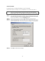
STATIC IP MODE
In static IP mode, you assign IP settings to your PC manually.
Follow these steps to configure your PC IP address to use subnet 192.168.1.x.
NOTE:
The following procedure assumes you are running Windows XP.
However, the general steps involved are similar for most operating
systems (OS). Check your OS support documentation for further details.
STEP 1: From the Network Connections window, open Local Area Connection (You
may also access this screen by double-clicking the Local Area Connection
icon on your taskbar). Click the Properties button.
STEP 2: Select Internet Protocol (TCP/IP) and click the Properties button.
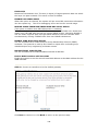
STEP 3: Change the IP address to the 192.168.1.x (1<x<255) subnet with subnet
mask of 255.255.255.0. The screen should now display as shown below.
STEP 4: Click OK to submit these settings.
11
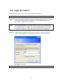
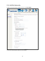
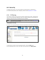
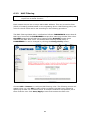
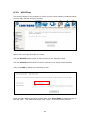
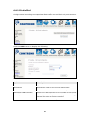
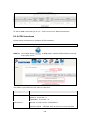
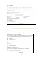
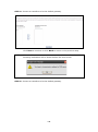
3.3 Login Procedure
Perform the following steps to login to the web user interface.
NOTE:
The default settings can be found in section 3.1 Default Settings.
STEP 1: Start the Internet browser and enter the default IP address for the device
in the Web address field. For example, if the default IP address is
192.168.1.1, type http://192.168.1.1.
NOTE:
For local administration (i.e. LAN access), the PC running the browser
must be attached to the Ethernet, and not necessarily to the device.
For remote access (i.e. WAN), use the IP address shown on the Device
Information screen and login with remote username and password.
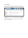
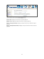
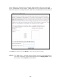
STEP 2: A dialog box will appear, such as the one below. Enter the default
username and password, as defined in section 3.1 Default Settings.
Click OK to continue.
NOTE:
The login password can be changed later (see section 8.6.1 Passwords).
12
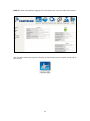
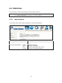
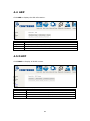
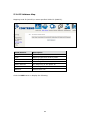
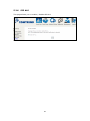
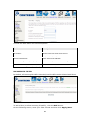
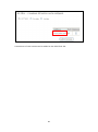
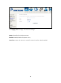
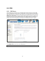
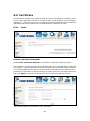
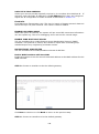
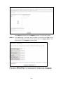
STEP 3: After successfully logging in for the first time, you will reach this screen.
You can also reach this page by clicking on the following icon located at the top of
the screen.
13
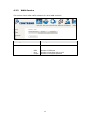
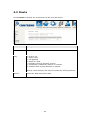
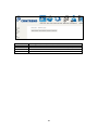
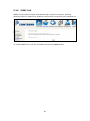
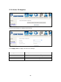
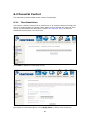
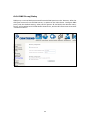
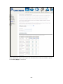
Chapter 4 Device Information
You can reach this page by clicking on the following icon located at the top of the
screen.
The web user interface window is divided into two frames, the main menu (at left)
and the display screen (on the right). The main menu has several options and
selecting each of these options opens a submenu with more selections.
NOTE:
The menu items shown are based upon the configured connection(s) and
user account privileges. For example, if NAT and Firewall are enabled, the
main menu will display the NAT and Security submenus. If either is
disabled, their corresponding menu(s) will also be disabled.
Device Info is the first selection on the main menu so it will be discussed first.
Subsequent chapters will introduce the other main menu options in sequence.
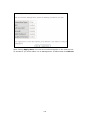
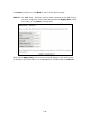
The Device Info Summary screen displays at startup.
This screen shows hardware, software, IP settings and other related information.
14
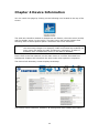
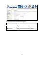
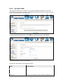
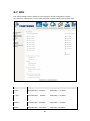
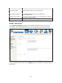
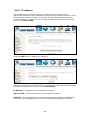
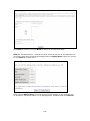
4.1 WAN
Select WAN from the Device Info submenu to display the configured PVC(s).
Heading
Description
Interface
Name of the interface for WAN
Description
Name of the WAN connection
Type
Shows the connection type
VlanMuxId
Shows 802.1Q VLAN ID
IPv6
Shows WAN IPv6 status
IGMP
Shows Internet Group Management Protocol (IGMP)
status
MLD
Shows Multicast Listener Discovery (MLD) status
NAT
Shows Network Address Translation (NAT) status
Firewall
Shows the status of Firewall
Status
Lists the status of DSL link
IPv4 Address
Shows WAN IPv4 address
IPv6 Address
Shows WAN IPv6 address
15
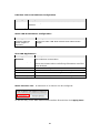
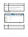
4.2 Statistics
This selection provides LAN, WAN, ATM and xDSL statistics.
NOTE:
4.2.1
These screens are updated automatically every 15 seconds.
Click Reset Statistics to perform a manual update.
LAN Statistics
This screen shows data traffic statistics for each LAN interface.
Heading
Description
Interface
LAN interface(s)
Received/Transmitted:
-
Bytes
Pkts
Errs
Drops
Number
Number
Number
Number
16
of
of
of
of
Bytes
Packets
packets with errors
dropped packets
4.2.2
WAN Service
This screen shows data traffic statistics for each WAN interface.
Heading
Description
Interface
WAN interfaces
Description
WAN service label
Received/Transmitted
- Bytes
- Pkts
- Errs
- Drops
Number
Number
Number
Number
17
of
of
of
of
Bytes
Packets
packets with errors
dropped packets
4.2.3
XTM Statistics
The following figure shows ATM (Asynchronous Transfer Mode)/PTM(Packet Transfer
Mode) statistics.
ATM Interface Statistics
Heading
Description
Port Number
ATM PORT (0-3)
In Octets
Number of octets received over the interface
Out Octets
Number of octets transmitted over the interface
In Packets
Number of packets received over the interface
Out Packets
Number of packets transmitted over the interface
In OAM Cells
Number of OAM Cells received over the interface
Out OAM Cells
Number of OAM Cells transmitted over the interface
In ASM Cells
Number of ASM Cells received over the interface
Out ASM Cells
Number of ASM Cells transmitted over the interface
In Packet Errors
Number of packets in Error
In Cell Errors
Number of cells in Error
18
4.2.4
xDSL Statistics
The xDSL Statistics screen displays information corresponding to the xDSL type.
The two examples below (VDSL & ADSL) show this variation.
VDSL
19
ADSL
Click the Reset Statistics button to refresh this screen.
Field
Description
Mode
G.Dmt, G.lite, T1.413, ADSL2, ADSL2+
Traffic Type
Channel type Interleave or Fast
Status
Lists the status of the DSL link
Link Power State
Link output power state
Line Coding (Trellis)
Trellis On/Off
SNR Margin (0.1 dB)
Signal to Noise Ratio (SNR) margin
Attenuation (0.1 dB)
Estimate of average loop attenuation in the downstream
direction
Output Power (0.1 dBm)
Total upstream output power
20
Field
Description
Attainable Rate (Kbps)
The sync rate you would obtain
Rate (Kbps)
Current sync rates downstream/upstream
In VDSL mode, the following section is inserted.
B
Number of bytes in Mux Data Frame
M
Number of Mux Data Frames in a RS codeword
T
Number of Mux Data Frames in an OH sub-frame
R
Number of redundancy bytes in the RS codeword
S
Number of data symbols the RS codeword spans
L
Number of bits transmitted in each data symbol
D
The interleaver depth
I
The interleaver block size in bytes
N
RS codeword size
Delay
The delay in milliseconds (msec)
INP
DMT symbol
In ADSL2+ mode, the following section is inserted.
MSGc
Number of bytes in overhead channel message
B
Number of bytes in Mux Data Frame
M
Number of Mux Data Frames in FEC Data Frame
T
Mux Data Frames over sync bytes
R
Number of check bytes in FEC Data Frame
S
Ratio of FEC over PMD Data Frame length
L
Number of bits in PMD Data Frame
D
The interleaver depth
Delay
The delay in milliseconds (msec)
INP
DMT symbol
In G.DMT mode, the following section is inserted.
K
Number of bytes in DMT frame
R
Number of check bytes in RS code word
S
RS code word size in DMT frame
D
The interleaver depth
Delay
The delay in milliseconds (msec)
Super Frames
Total number of super frames
Super Frame Errors
Number of super frames received with errors
RS Words
Total number of Reed-Solomon code errors
RS Correctable Errors
Total Number of RS with correctable errors
RS Uncorrectable Errors
Total Number of RS words with uncorrectable errors
21
HEC Errors
Total Number of Header Error Checksum errors
OCD Errors
Total Number of Out-of-Cell Delineation errors
LCD Errors
Total number of Loss of Cell Delineation
Total Cells
Total number of ATM cells (including idle + data cells)
Data Cells
Total number of ATM data cells
Bit Errors
Total number of bit errors
Total ES
Total Number of Errored Seconds
Total SES
Total Number of Severely Errored Seconds
Total UAS
Total Number of Unavailable Seconds
xDSL BER TEST
Click xDSL BER Test on the xDSL Statistics screen to test the Bit Error Rate (BER).
A small pop-up window will open after the button is pressed, as shown below.
Click Start to start the test or click Close to cancel the test. After the BER testing is
complete, the pop-up window will display as follows.
22
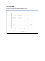
xDSL TONE GRAPH
Click Draw Tone Graph on the xDSL Statistics screen and a pop-up window will
display the xDSL bits per tone status, as shown below.
23
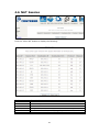
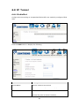
4.3 Route
Choose Route to display the routes that the VR-3030 has found.
Field
Description
Destination
Destination network or destination host
Gateway
Next hop IP address
Subnet Mask
Subnet Mask of Destination
Flag
U: route is up
!: reject route
G: use gateway
H: target is a host
R: reinstate route for dynamic routing
D: dynamically installed by daemon or redirect
M: modified from routing daemon or redirect
Metric
The 'distance' to the target (usually counted in hops). It is not
used by recent kernels, but may be needed by routing daemons.
Service
Shows the WAN connection label
Interface
Shows connection interfaces
24
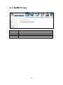
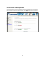
4.4 ARP
Click ARP to display the ARP information.
Field
IP address
Flags
HW Address
Device
Description
Shows IP address of host pc
Complete, Incomplete, Permanent, or Publish
Shows the MAC address of host pc
Shows the connection interface
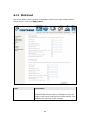
4.5 DHCP
Click DHCP to display all DHCP Leases.
Field
IPv6 Address
MAC Address
IP Address
Expires In
Description
Shows IP address of device/host/PC
Shows the Ethernet MAC address of the device/host/PC
Shows IP address of device/host/PC
Shows how much time is left for each DHCP Lease
25
Field
IPv6 Address
MAC Address
Duration
Expires In
Description
Shows IP address of device/host/PC
Shows the Ethernet MAC address of the device/host/PC
Shows leased time in hours
Shows how much time is left for each DHCP Lease
26
4.6 NAT Session
Click the “Show All” button to display the following.
Field
Source IP
Source Port
Destination IP
Destination Port
Protocol
Timeout
Description
The source IP from which the NAT session is established
The source port from which the NAT session is established
The IP which the NAT session was connected to
The port which the NAT session was connected to
The Protocol used in establishing the particular NAT session
The time remaining for the TCP/UDP connection to be active
27
4.7 IGMP Proxy
Field
Interface
WAN
Groups
Member
Timeout
Description
The Source interface from which the IGMP report was received
The WAN interface from which the multicast traffic is received
The destination IGMP group address
The Source IP from which the IGMP report was received
The time remaining before the IGMP report expires
28
4.8 IPv6
4.8.1 IPv6 Info
Field
Interface
Status
Address
Prefix
Device Link-local Address
Default IPv6 Gateway
IPv6 DNS Server
Description
WAN interface with IPv6 enabled
Connection status of the WAN interface
IPv6 Address of the WAN interface
Prefix received/configured on the WAN interface
The CPE's LAN Address
The default WAN IPv6 gateway
The IPv6 DNS servers received from the WAN interface
/ configured manually
29
4.8.2 IPv6 Neighbor
Field
IPv6 Address
Flags
HW Address
Device
Description
Ipv6 address of the device(s) found
Status of the neighbor device
MAC address of the neighbor device
Interface from which the device is located
30
4.8.3 IPv6 Route
Field
Destination
Gateway
Metric
Interface
Description
Destination IP Address
Gateway address used for destination IP
Metric specified for gateway
Interface used for destination IP
4.8.4 Network Map
The network map is a graphical representation of router’s wan status and LAN
devices. The feature is only available using a non-IE browser.
31
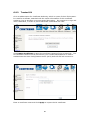
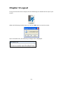
Chapter 5 Basic Setup
You can reach this page by clicking on the following icon located at the top of the
screen.
5.1 Layer 2 Interface
Add or remove ATM, PTM and ETH WAN interface connections here.
Click Add to create a new ATM interface (see Appendix E - Connection Setup).
NOTE:
Up to 8 ATM interfaces can be created and saved in flash memory.
To remove a connection, select its Remove column radio button and click Remove.
32
5.1.1 WAN Service Setup
This screen allows for the configuration of WAN interfaces.
Click the Add button to create a new connection. For connections on ATM or ETH
WAN interfaces see Appendix E - Connection Setup.
To remove a connection, select its Remove column radio button and click Remove.
Heading
Description
Interface
Name of the interface for WAN
Description
Name of the WAN connection
Type
Shows the connection type
Vlan8021p
VLAN ID is used for VLAN Tagging (IEEE 802.1Q)
VlanMuxId
Shows 802.1Q VLAN ID
IGMP
Shows Internet Group Management Protocol (IGMP) status
NAT
Shows Network Address Translation (NAT) status
Firewall
Shows the Security status
IPv6
Shows the WAN IPv6 address
MLD
Shows Multicast Listener Discovery (MLD) status
Remove
Select interfaces to remove
To remove a connection, select its Remove column radio button and click Remove.
NOTE:
ETH and ATM service connections cannot coexist. In Default Mode, up to
8 WAN connections can be configured; while VLAN Mux Connection Mode
supports up to 16 WAN connections.
NOTE:
Up to 16 PVC profiles can be configured and saved in flash memory.
Also, ETH and PTM/ATM service connections cannot coexist.
33
5.2 NAT
To display this option, NAT must be enabled in at least one PVC shown on the
Advanced Setup WAN screen. NAT is not an available option in Bridge mode.
5.2.1
Virtual Servers
Virtual Servers allow you to direct incoming traffic from the WAN side (identified by
Protocol and External port) to the internal server with private IP addresses on the
LAN side. The Internal port is required only if the external port needs to be
converted to a different port number used by the server on the LAN side.
A maximum of 32 entries can be configured.
To add a Virtual Server, click Add. The following will be displayed.
34
Consult the table below for field and header descriptions.
Field/Header
Description
Use Interface
Select a WAN interface from the drop-down box.
Select a Service
Or
Custom Service
User should select the service from the list.
Or
User can enter the name of their choice.
Server IP Address
Enter the IP address for the server.
Enable NAT
Loopback
Allows local machines to access virtual server via WAN IP
Address
External Port Start
Enter the starting external port number (when you select
Custom Server). When a service is selected, the port ranges
are automatically configured.
External Port End
Enter the ending external port number (when you select
Custom Server). When a service is selected, the port ranges
are automatically configured.
Protocol
TCP, TCP/UDP, or UDP.
Internal Port Start
Enter the internal port starting number (when you select
Custom Server). When a service is selected the port ranges
are automatically configured
Internal Port End
Enter the internal port ending number (when you select
Custom Server). When a service is selected, the port ranges
are automatically configured.
5.2.2
Port Triggering
Some applications require that specific ports in the firewall be opened for access by
the remote parties. Port Triggers dynamically 'Open Ports' in the firewall when an
application on the LAN initiates a TCP/UDP connection to a remote party using the
'Triggering Ports'. The Router allows the remote party from the WAN side to
establish new connections back to the application on the LAN side using the 'Open
Ports'. A maximum 32 entries can be configured.
To add a Trigger Port, click Add. The following will be displayed.
35
Click Save/Apply to save and apply the settings.
Consult the table below for field and header descriptions.
Field/Header
Description
Use Interface
Select a WAN interface from the drop-down box.
Select an Application
Or
Custom Application
User should select the application from the list.
Or
User can enter the name of their choice.
Trigger Port Start
Enter the starting trigger port number (when you select
custom application). When an application is selected, the
port ranges are automatically configured.
Trigger Port End
Enter the ending trigger port number (when you select
custom application). When an application is selected, the
port ranges are automatically configured.
Trigger Protocol
TCP, TCP/UDP, or UDP.
Open Port Start
Enter the starting open port number (when you select
custom application). When an application is selected, the
port ranges are automatically configured.
Open Port End
Enter the ending open port number (when you select
custom application). When an application is selected, the
port ranges are automatically configured.
Open Protocol
TCP, TCP/UDP, or UDP.
36
5.2.3
DMZ Host
The DSL router will forward IP packets from the WAN that do not belong to any of
the applications configured in the Virtual Servers table to the DMZ host computer.
To Activate the DMZ host, enter the DMZ host IP address and click Save/Apply.
To Deactivate the DMZ host, clear the IP address field and click Save/Apply.
Enable NAT Loopback allows PC on the LAN side to access servers in the LAN
network via the router’s WAN IP.
37
5.2.4 IP Address Map
Mapping Local IP (LAN IP) to some specified Public IP (WAN IP).
Field/Header
Description
Rule
The number of the rule
Type
Mapping type from local to public.
Local Start IP
The beginning of the local IP
Local End IP
The ending of the local IP
Public Start IP
The beginning of the public IP
Public End IP
The ending of the public IP
Remove
Remove this rule
Click the Add button to display the following.
38
Select a Service, then click the Save/Apply button.
One to One: mapping one local IP to a specific public IP
Many to one: mapping a range of local IP to a specific public IP
Many to many(Overload): mapping a range of local IP to a different range of
public IP
Many to many(No Overload): mapping a range of local IP to a same range of
public IP
39
5.2.5 IPSEC ALG
IPSEC ALG provides multiple VPN passthrough connection support, allowing
different clients on LAN side to establish a secured IP Connection to the WAN server.
To enable IPSEC ALG, tick the checkbox and click the Save button.
40
5.2.6 SIP ALG
This page allows you to enable / disable SIP ALG.
41
5.3 LAN
Configure the LAN interface settings and then click Apply/Save.
Consult the field descriptions below for more details.
GroupName: Select an Interface Group.
1st LAN INTERFACE
IP Address: Enter the IP address for the LAN port.
Subnet Mask: Enter the subnet mask for the LAN port.
42
IGMP Snooping:
Standard Mode: In standard mode, multicast traffic will flood to all
bridge ports when no client subscribes to a multicast
group – even if IGMP snooping is enabled.
Blocking Mode: In blocking mode, the multicast data traffic will be
blocked and not flood to all bridge ports when there are
no client subscriptions to any multicast group.
Enable LAN side firewall: Enable by ticking the checkbox .
DHCP Server: To enable DHCP, select Enable DHCP server and enter Start and
End IP addresses and the Leased Time. This setting configures the
router to automatically assign IP, default gateway and DNS server
addresses to every PC on your LAN.
Setting TFTP Server: Enable by ticking the checkbox . Then, input the TFTP
server address or an IP address.
Static IP Lease List:
A maximum of 32 entries can be configured.
To add an entry, enter MAC address and static IP address and then click
Apply/Save.
To remove an entry, tick the corresponding checkbox in the Remove column and
then click the Remove Entries button, as shown below.
43
2ND LAN INTERFACE
To configure a secondary IP address, tick the checkbox outlined (in RED) below.
IP Address: Enter the secondary IP address for the LAN port.
Subnet Mask: Enter the secondary subnet mask for the LAN port.
Ethernet Media Type:
Configure auto negotiation, or enforce selected speed and duplex mode for the
Ethernet port.
44
5.3.1 LAN IPv6 Autoconfig
Configure the LAN interface settings and then click Save/Apply.
Consult the field descriptions below for more details.
45
LAN IPv6 Link-Local Address Configuration
Heading
Description
EUI-64
Use EUI-64 algorithm to calculate link-local address from MAC
address
User Setting
Use the Interface Identifier field to define a link-local address
Static LAN IPv6 Address Configuration
Heading
Description
Interface Address
(prefix length is
required):
Configure static LAN IPv6 address and subnet prefix
length
IPv6 LAN Applications
Heading
Description
Stateless
Use stateless configuration
Refresh Time (sec):
The information refresh time option specifies how long a
client should wait before refreshing information retrieved
from DHCPv6
Use stateful configuration
Stateful
Start interface ID:
Start of interface ID to be assigned to dhcpv6 client
End interface ID:
End of interface ID to be assigned to dhcpv6 client
Leased Time (hour):
Lease time for dhcpv6 client to use the assigned IP address
Static IP Lease List:
A maximum of 32 entries can be configured.
To add an entry, enter MAC address and Interface ID and then click Apply/Save.
46
To remove an entry, tick the corresponding checkbox in the Remove column and
then click the Remove Entries button, as shown below.
Heading
Description
Enable RADVD
Enable use of router advertisement daemon
RA interval Min(sec):
Minimum time to send router advertisement
RA interval Max(sec):
Maximum time to send router advertisement
Reachable Time(ms):
The time, in milliseconds that a neighbor is
reachable after receiving reachability
confirmation
Preference level associated with the default
router
MTU value used in router advertisement
messages to insure that all nodes on a link use
the same MTU value
Use prefix length receive from WAN interface
Default Preference:
MTU (bytes):
Enable Prefix Length Relay
Enable Configuration Mode
Randomly Generate
Manually configure prefix, prefix length,
preferred lifetime and valid lifetime used in
router advertisement
Allow RADVD to advertise Unique Local Address
Prefix
Use a Randomly Generated Prefix
Statically Configure Prefix
Specify the prefix to be used
Statically Configure
The prefix to be used
Enable ULA Prefix Advertisement
Preferred Life Time (hour)
The preferred life time for this prefix
Valid Life Time (hour)
The valid life time for this prefix
Enable MLD Snooping
Enable/disable IPv6 multicast forward to LAN
ports
47
5.3.2 Static IP Neighbor
Click the Add button to display the following.
Click Apply/Save to apply and save the settings.
Heading
Description
IP Version
The IP version used for the neighbor device
IP Address
MAC Address
Define the IP Address for the neighbor device
The MAC Address of the neighbor device
Associated Interface
The interface where the neighbor device is located
48
5.3.3 UPnP
Select the checkbox provided and click Apply/Save to enable UPnP protocol.
49
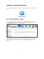
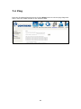
Chapter 6 Advanced Setup
You can reach this page by clicking on the following icon located at the top of the
screen.
6.1 Auto-detection setup
The auto-detection function is used for CPE to detect WAN service for either
ETHWAN or xDSL interface. The feature is designed for the scenario that requires
only one WAN service in different applications.
The Auto Detection page simply provides a checkbox allowing users to enable or
disable the feature. Check the checkbox to display the following configuration
options.
50
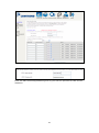
Enter the PPP username/password given by your service provider for PPP service
detection.
51
WAN services list for ATM mode: A maximum of 7 WAN services with
corresponding PVC are required to be configured for ADSL ATM mode. The services
will be detected in order. Users can modify the 7 pre-configured services and select
disable to ignore any of those services to meet their own requirement and also
reduce the detection cycle.
WAN services list for PTM mode: A maximum of 7 WAN services with
corresponding VLAN ID (-1 indicates no VLAN ID is required for the service) are
required to be configured for ADSL/VDSL PTM mode and ETHWAN. The services will
be detected in order. Users can modify the 7 pre-configured services and select
disable to ignore any of the services to meet their own requirement and also reduce
the detection cycle.
52
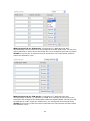
Click "Apply/Save" to activate the auto-detect function.
Options for each WAN service: These options are selectable for each WAN
service. Users can pre-configure both WAN services and other provided settings to
meet their deployed requirements.
Auto Detection status and Restart
The Auto-detection status is used to display the real time status of the
Auto-detection feature.
The Restart button is used to detect all the WAN services that are either detected
by the auto-detection feature or configured manually by users.
The following window will pop up upon clicking the Restart button. Click the OK
button to proceed.
Auto Detection notice
Note: The following description concerning ETHWAN is for multiple LAN port devices
only.
1) This feature will automatically detect one WAN service only. If customers require
multiple WAN services, manual configuration is required.
53
2) If a physical ETHWAN port is detected, the Auto Detection for ETHWAN will be
fixed on the physical ETHWAN port and cannot be configured for any LAN port;
if the physical ETHWAN port is not detected, the Auto Detection for ETHWAN will
be configured to the 4th LAN port by default and allows it to be configured for any
LAN port as well.
3) For cases in which both the DSL port and ETHWAN port are plugged in at the
same time, the DSL WAN will have priority over ETHWAN. For example, the
ETHWAN port is plugged in with a WAN service detected automatically and then
the DSL port is plugged in and linked up. The Auto Detection feature will clear
the WAN service for ETHWAN and re-detect the WAN service for DSL port.
4) If none of the pre-configured services are detected, a Bridge service will be
created.
54
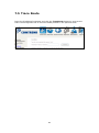
6.2 Security
To display this function, you must enable the firewall feature in WAN Setup.
For detailed descriptions, with examples, please consult Appendix A - Firewall.
6.2.1
IP Filtering
This screen sets filter rules that limit IP traffic (Outgoing/Incoming). Multiple filter
rules can be set and each applies at least one limiting condition. For individual IP
packets to pass the filter all conditions must be fulfilled.
NOTE:
This function is not available when in bridge mode. Instead, MAC Filtering
performs a similar function.
OUTGOING IP FILTER
By default, all outgoing IP traffic is allowed, but IP traffic can be blocked with filters.
To add a filter (to block some outgoing IP traffic), click the Add button.
On the following screen, enter your filter criteria and then click Apply/Save.
55
Consult the table below for field descriptions.
Field
Description
Filter Name
The filter rule label
IP Version
Select from the drop down menu.
Protocol
TCP, TCP/UDP, UDP, or ICMP.
Source IP address
Enter source IP address.
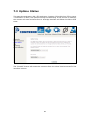
Source Port (port or port:port)
Enter source port number or range.
Destination IP address
Enter destination IP address.
Destination Port (port or port:port)
Enter destination port number or range.
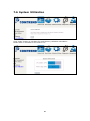
INCOMING IP FILTER
By default, all incoming IP traffic is blocked, but IP traffic can be allowed with filters.
To add a filter (to allow incoming IP traffic), click the Add button.
On the following screen, enter your filter criteria and then click Apply/Save.
56
Consult the table below for field descriptions.
Field
Description
Filter Name
The filter rule label.
IP Version
Select from the drop down menu.
Protocol
TCP, TCP/UDP, UDP, or ICMP.
Policy
Permit/Drop packets specified by the firewall
rule.
Source IP address
Enter source IP address.
Source Port (port or port:port)
Enter source port number or range.
Destination IP address
Enter destination IP address.
Destination Port (port or port:port)
Enter destination port number or range.
At the bottom of this screen, select the WAN and LAN Interfaces to which the filter
rule will apply. You may select all or just a subset. WAN interfaces in bridge mode or
without firewall enabled are not available.
57
6.2.2
NOTE:
MAC Filtering
This option is only available in bridge mode. Other modes use IP Filtering
to perform a similar function.
Each network device has a unique 48-bit MAC address. This can be used to filter
(block or forward) packets based on the originating device. MAC filtering policy and
rules for the VR-3030 can be set according to the following procedure.
The MAC Filtering Global Policy is defined as follows. FORWARDED means that all
MAC layer frames will be FORWARDED except those matching the MAC filter rules.
BLOCKED means that all MAC layer frames will be BLOCKED except those
matching the MAC filter rules. The default MAC Filtering Global policy is
FORWARDED. It can be changed by clicking the Change Policy button.
Choose Add or Remove to configure MAC filtering rules. The following screen will
appear when you click Add. Create a filter to identify the MAC layer frames by
specifying at least one condition below. If multiple conditions are specified, all of
them must be met. Click Save/Apply to save and activate the filter rule.
58
Consult the table below for detailed field descriptions.
Field
Description
Protocol Type
PPPoE, IPv4, IPv6, AppleTalk, IPX, NetBEUI, IGMP
Destination MAC Address
Defines the destination MAC address
Source MAC Address
Defines the source MAC address
Frame Direction
Select the incoming/outgoing packet interface
WAN Interfaces
Applies the filter to the selected bridge interface.
59
6.3 Parental Control
This selection provides WAN access control functionality.
6.3.1
Time Restriction
This feature restricts access from a LAN device to an outside network through the
device on selected days at certain times. Make sure to activate the Internet Time
server synchronization as described in section 8.5 Internet Time, so that the
scheduled times match your local time.
Click Add to display the following screen.
See below for field descriptions. Click Apply/Save to add a time restriction.
60
User Name: A user-defined label for this restriction.
Browser's MAC Address: MAC address of the PC running the browser.
Other MAC Address: MAC address of another LAN device.
Days of the Week: The days the restrictions apply.
Start Blocking Time: The time the restrictions start.
End Blocking Time: The time the restrictions end.
61
6.3.2
URL Filter
This screen allows for the creation of a filter rule for access rights to websites based
on their URL address and port number.
Select URL List Type: Exclude or Include.
Tick the Exclude radio button to deny access to the websites listed.
Tick the Include radio button to restrict access to only those listed websites.
Then click Add to display the following screen.
Enter the URL address and port number then click Save/Apply to add the entry to
the URL filter. URL Addresses begin with “www”, as shown in this example.
62
A maximum of 100 entries can be added to the URL Filter list.
63
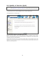
6.4 Quality of Service (QoS)
NOTE:
QoS must be enabled in at least one PVC to display this option.
(see Appendix E - Connection Setup for detailed PVC setup instructions).
To Enable QoS tick the checkbox
and select a Default DSCP Mark.
Click Apply/Save to activate QoS.
QoS and DSCP Mark are defined as follows:
Quality of Service (QoS): This provides different priority to different users or data
flows, or guarantees a certain level of performance to a data flow in accordance with
requests from Queue Prioritization.
Default Differentiated Services Code Point (DSCP) Mark: This specifies the per hop
behavior for a given flow of packets in the Internet Protocol (IP) header that do not
match any other QoS rule.
64
6.4.1
QoS Queue Setup
Configure queues with different priorities to be used for QoS setup.
In ATM mode, maximum 16 queues can be configured.
In PTM mode, maximum 8 queues can be configured.
For each Ethernet interface, maximum 3 queues can be configured.
To add a queue, click the Add button.
To remove queues, check their remove-checkboxes, then click the Remove button.
The Enable button will scan through every queues in the table. Queues with
enable-checkbox checked will be enabled. Queues with enable-checkbox
un-checked will be disabled.
The enable-checkbox also shows status of the queue after page reload.
Note that if WMM function is disabled in Wireless Page, queues related to wireless
will not take effect. This function follows the Differentiated Services rule of IP QoS.
You can create a new Queue entry by clicking the Add button.
Enable and assign an interface and precedence on the next screen. Click
Save/Reboot on this screen to activate it.
Click Add to display the following screen.
65
Click Apply/Save to apply and save the settings.
Name: Identifier for this Queue entry.
Enable: Enable/Disable the Queue entry.
Interface: Assign the entry to a specific network interface (QoS enabled).
66
6.4.2
QoS Policer
To remove policers, check their remove-checkboxes, then click the Remove button.
The Enable button will scan through every policers in the table. Policers with
enable-checkbox checked will be enabled. Policers with enable-checkbox
un-checked will be disabled.
The enable-checkbox also shows status of the policer after page reload.
To add a policer, click the Add button.
Click Apply/Save to save the policer.
67
Field
Description
Name
Name of this policer rule
Enable
Enable/Disable this policer rule
Meter Type
Meter type used for this policer rule
Committed Rate (kbps)
Defines the rate allowed for committed packets
Committed Burst Size
(bytes)
Maximum amount of packets that can be processed by
this policer
Conforming Action
Defines action to be taken if packets match this policer
Nonconforming Action
Defines actions to be taken if packets do not match
this policer
68
6.4.3 QoS Classification
The network traffic classes are listed in the following table.
Click Add to configure a network traffic class rule and Enable to activate it. To
delete an entry from the list, click Remove.
This screen creates a traffic class rule to classify the upstream traffic, assign
queuing priority and optionally overwrite the IP header DSCP byte. A rule consists of
a class name and at least one logical condition. All the conditions specified in the
rule must be satisfied for it to take effect.
69
Click Apply/Save to save and activate the rule.
Field
Description
Traffic Class Name
Enter a name for the traffic class.
Rule Order
Last is the only option.
Rule Status
Disable or enable the rule.
Classification Criteria
Class Interface
Select an interface (i.e. Local, eth0-4, wl0)
Ether Type
Set the Ethernet type (e.g. IP, ARP, IPv6).
Source MAC Address
A packet belongs to SET-1, if a binary-AND of its source
MAC address with the Source MAC Mask is equal to the
binary-AND of the Source MAC Mask and this field.
Source MAC Mask
This is the mask used to decide how many bits are checked
in Source MAC Address.
Destination MAC
Address
A packet belongs to SET-1 then the result that the
Destination MAC Address of its header binary-AND to the
Destination MAC Mask must equal to the result that this
field binary-AND to the Destination MAC Mask.
Destination MAC Mask
This is the mask used to decide how many bits are checked
in Destination MAC Address.
70
Field
Description
Classification Results
Specify Class Queue
Packets classified into a queue that exit through an
interface for which the queue is not specified to exist, will
instead egress to the default queue on the interface.
Specify Class Policer
Packets classified into a policer will be marked based on
the conforming action of the policer
Mark Differentiated
Service Code Point
The selected Code Point gives the corresponding priority to
packets that satisfy the rule.
Mark 802.1p Priority
Select between 0-7. Lower values have higher priority.
Set Rate Limit
The data transmission rate limit in kbps.
71
6.5 Routing
The following routing functions are accessed from this menu:
Default Gateway, Static Route, Policy Routing, RIP and IPv6 Static Route.
NOTE:
6.5.1
In bridge mode, the RIP menu option is hidden while the other menu
options are shown but ineffective.
Default Gateway
Default gateway interface list can have multiple WAN interfaces served as system
default gateways but only one will be used according to the priority with the first
being the highest and the last one the lowest priority if the WAN interface is
connected. Priority order can be changed by removing all and adding them back in
again.
72
6.5.2
Static Route
This option allows for the configuration of static routes by destination IP.
Click Add to create a static route or click Remove to delete a static route.
After clicking Add the following will display.
IP Version: Select the IP version to be IPv4.
Destination IP address/prefix length: Enter the destination IP address.
Interface: select the proper interface for the rule.
Gateway IP Address: The next-hop IP address.
Metric: The metric value of routing.
After completing the settings, click Apply/Save to add the entry to the routing
table.
73
6.5.3
Policy Routing
This option allows for the configuration of static routes by policy.
Click Add to create a routing policy or Remove to delete one.
On the following screen, complete the form and click Apply/Save to create a policy.
Field
Description
Policy Name
Name of the route policy
Physical LAN Port
Specify the port to use this route policy
Source IP
IP Address to be routed
Use Interface
Interface that traffic will be directed to
Default Gateway IP
IP Address of the default gateway
74
6.5.4
RIP
To activate RIP, configure the RIP version/operation mode and select the Enabled
checkbox for at least one WAN interface before clicking Save/Apply.
75
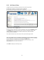
6.6 DNS
6.6.1
DNS Server
Select DNS Server Interface from available WAN interfaces OR enter static DNS
server IP addresses for the system. In ATM mode, if only a single PVC with IPoA or
static IPoE protocol is configured, Static DNS server IP addresses must be entered.
DNS Server Interfaces can have multiple WAN interfaces served as system dns
servers but only one will be used according to the priority with the first being the
highest and the last one the lowest priority if the WAN interface is connected.
Priority order can be changed by removing all and adding them back in again.
Click Apply/Save to save the new configuration.
NOTE:
You must reboot the router to make the new configuration effective.
76
6.6.2
Dynamic DNS
The Dynamic DNS service allows you to map a dynamic IP address to a static
hostname in any of many domains, allowing the VR-3030 to be more easily accessed
from various locations on the Internet.
To add a dynamic DNS service, click Add. The following screen will display.
Click Apply/Save to save your settings.
Consult the table below for field descriptions.
Field
Description
D-DNS provider
Select a dynamic DNS provider from the list
Hostname
Enter the name of the dynamic DNS server
Interface
Select the interface from the list
Username
Enter the username of the dynamic DNS server
Password
Enter the password of the dynamic DNS server
77
6.6.3
DNS Entries
The DNS Entry page allows you to add domain names and IP address desired to be
resolved by the DSL router.
Choose Add or Remove to configure DNS Entry. The entries will become active after
save/reboot.
Enter the domain name and IP address that needs to be resolved locally, and click
the Add Entry button.
78
6.6.4 DNS Proxy/Relay
DNS proxy receives DNS queries and forwards DNS queries to the Internet. After the
CPE gets answers from the DNS server, it replies to the LAN clients. Configure DNS
proxy with the default setting, when the PC gets an IP via DHCP, the domain name,
Home, will be added to PC’s DNS Suffix Search List, and the PC can access route with
“Comtrend.Home”.
79
6.7 DSL
The DSL Settings screen allows for the selection of DSL modulation modes.
For optimum performance, the modes selected should match those of your ISP.
DSL Mode
Data Transmission Rate - Mbps (Megabits per second)
G.Dmt
Downstream: 12 Mbps
Upstream: 1.3 Mbps
G.lite
Downstream:
4 Mbps
Upstream: 0.5 Mbps
T1.413
Downstream:
8 Mbps
Upstream: 1.0 Mbps
ADSL2
Downstream: 12 Mbps
Upstream: 1.0 Mbps
AnnexL
Supports longer loops but with reduced transmission rates
ADSL2+
Downstream: 24 Mbps
Upstream: 1.0 Mbps
AnnexM
Downstream: 24 Mbps
Upstream: 3.5 Mbps
VDSL2
Downstream: 100 Mbps
Upstream: 60 Mbps
80
DSL Mode
Data Transmission Rate - Mbps (Megabits per second)
Options
Description
Inner/Outer Pair
Select the inner or outer pins of the twisted pair (RJ11 cable)
Bitswap Enable
Enables adaptive handshaking functionality
SRA Enable
Enables Seamless Rate Adaptation (SRA)
Select DSL LED
behavior
Normal (TR-68 compliant): Select this option for DSL LED to
operate normally (See menu 2.2 LED Indicator)
Off: DSL LED will always be OFF
G997.1 EOC
xTU-R Serial
Number
Select Equipment Serial Number or Equipment MAC Address to
use router’s serial number or MAC address in ADSL EOC
messages
Advanced DSL Settings
Click Advanced Settings to reveal additional options.
On this screen you select the required test mode, then click the Apply button.
Field
Description
Normal
DSL line signal is detected and sent normally
Reverb
DSL line signal is sent continuously in reverb mode
Medley
DSL line signal is sent continuously in medley mode
No Retrain
DSL line signal will always be on even when DSL line is unplugged
L3
DSL line is set in L3 power mode
81
6.8 IP Tunnel
6.8.1 IPv6inIPv4
Configure 6in4 tunneling to encapsulate IPv6 traffic over explicitly-configured IPv4
links.
Click the Add button to display the following.
Options
Description
Tunnel Name
Input a name for the tunnel
Mechanism
Mechanism used by the tunnel deployment
Associated WAN Interface
Select the WAN interface to be used by the tunnel
Associated LAN Interface
Select the LAN interface to be included in the tunnel
Manual/Automatic
Select automatic for point-to-multipoint tunneling /
manual for point-to-point tunneling
82
Options
Description
IPv4 Mask Length
The subnet mask length used for the IPv4 interface
6rd Prefix with Prefix Length
Prefix and prefix length used for the IPv6 interface
Border Relay IPv4 Address
Input the IPv4 address of the other device
83
6.8.2 IPv4inIPv6
Configure 4in6 tunneling to encapsulate IPv4 traffic over an IPv6-only environment.
Click the Add button to display the following.
Options
Description
Tunnel Name
Input a name for the tunnel
Mechanism
Mechanism used by the tunnel deployment
Associated WAN Interface
Select the WAN interface to be used by the tunnel
Associated LAN Interface
Select the LAN interface to be included in the tunnel
Manual/Automatic
Select automatic for point-to-multipoint tunneling /
manual for point-to-point tunneling
AFTR
Address of Address Family Translation Router
84
6.9 Certificate
A certificate is a public key, attached with its owner’s information (company name,
server name, personal real name, contact e-mail, postal address, etc) and digital
signatures. There will be one or more digital signatures attached to the certificate,
indicating that these entities have verified that this certificate is valid.
6.9.1
Local
CREATE CERTIFICATE REQUEST
Click Create Certificate Request to generate a certificate-signing request.
The certificate-signing request can be submitted to the vendor/ISP/ITSP to apply for
a certificate. Some information must be included in the certificate-signing request.
Your vendor/ISP/ITSP will ask you to provide the information they require and to
provide the information in the format they regulate. Enter the required information
and click Apply to generate a private key and a certificate-signing request.
The following table is provided for your reference.
85
Field
Description
Certificate Name
A user-defined name for the certificate.
Common Name
Usually, the fully qualified domain name for the machine.
Organization Name
The exact legal name of your organization.
Do not abbreviate.
State/Province Name
The state or province where your organization is located.
It cannot be abbreviated.
Country/Region Name
The two-letter ISO abbreviation for your country.
IMPORT CERTIFICATE
Click Import Certificate to paste the certificate content and the private key
provided by your vendor/ISP/ITSP into the corresponding boxes shown below.
Enter a certificate name and click the Apply button to import the certificate and its
private key.
86
6.9.2
Trusted CA
CA is an abbreviation for Certificate Authority, which is a part of the X.509 system.
It is itself a certificate, attached with the owner information of this certificate
authority; but its purpose is not encryption/decryption. Its purpose is to sign and
issue certificates, in order to prove that these certificates are valid.
Click Import Certificate to paste the certificate content of your trusted CA. The
CA certificate content will be provided by your vendor/ISP/ITSP and is used to
authenticate the Auto-Configuration Server (ACS) that the CPE will connect to.
Enter a certificate name and click Apply to import the CA certificate.
87
6.10 Power Management
This screen allows for control of hardware modules to evaluate power consumption.
Use the buttons to select the desired option, click Apply and check the response.
88
6.11 Multicast
Input new IGMP or MLD protocol configuration fields if you want modify default
values shown. Then click Apply/Save.
Field
Description
Default Version
Define IGMP using version with video server.
Query Interval
The query interval is the amount of time in seconds
between IGMP General Query messages sent by the
router (if the router is the querier on this subnet). The
default query interval is 125 seconds.
89
Field
Description
Query Response Interval
The query response interval is the maximum amount
of time in seconds that the IGMP router waits to
receive a response to a General Query message. The
query response interval is the Maximum Response
Time field in the IGMP v2 Host Membership Query
message header. The default query response interval
is 10 seconds and must be less than the query
interval.
Last Member Query
Interval
The last member query interval is the amount of time
in seconds that the IGMP router waits to receive a
response to a Group-Specific Query message. The last
member query interval is also the amount of time in
seconds between successive Group-Specific Query
messages. The default last member query interval is
10 seconds.
Robustness Value
The robustness variable is a way of indicating how
susceptible the subnet is to lost packets. IGMP can
recover from robustness variable minus 1 lost IGMP
packets. The robustness variable should be set to a
value of 2 or greater. The default robustness variable
value is 2.
Maximum Multicast
Groups
Setting the maximum number of Multicast groups.
Maximum Multicast Data
Sources (for IGMPv3)
Define the maximum multicast video stream number.
Maximum Multicast
Group Members
Setting the maximum number of groups that ports
can accept.
Fast Leave Enable
When you enable IGMP fast-leave processing, the
switch immediately removes a port when it detects an
IGMP version 2 leave message on that port.
LAN to LAN (Intra LAN)
Multicast Enable
This will activate IGMP snooping for cases where
multicast data source and player are all located on the
LAN side.
Membership to join
Immediate (IPTV)
Enable IGMP immediate join feature for multicast
membership group.
90
Chapter 7 Diagnostics
You can reach this page by clicking on the following icon located at the top of the
screen.
7.1 Diagnostics – Individual Tests
The first Diagnostics screen is a dashboard that shows overall connection status.
91
7.2 Fault Management
Item
Description
Maintenance Domain (MD) Level
Management space on the network, the
larger the domain, the higher the level
value
Destination MAC Address
Destination MAC address for sending the
loopback message
802.1Q VLAN ID: [0-4095]
802.1Q VLAN used in VDSL PTM mode
Set MD Level
Save the Maintenance domain level.
Send Loopback
Send loopback message to destination MAC address.
Send Linktrace
Send traceroute message to destination MAC address.
92
7.3 Uptime Status
This page shows System, DSL, ETH and Layer 3 uptime. If the DSL line, ETH or Layer
3 connection is down, the uptime will stop incrementing. If the service is restored,
the counter will reset and start from 0. A Bridge interface will follow the DSL or ETH
timer.
The "ClearAll" button will restart the counters from 0 or show "Not Connected" if the
interface is down.
93
7.4 Ping
Input the IP address/hostname and click the Ping button to execute ping diagnostic
test to send the ICMP request to the specified host.
94
7.5 Trace Route
Input the IP address/hostname and click the TraceRoute button to execute the
trace route diagnostic test to send the ICMP packets to the specified host.
95
7.6 System Utilization
Click "Start" button to initialize CPU and Memory utilization calculation.
Please wait 10 seconds for the test to run.
96
Chapter 8 Management
You can reach this page by clicking on the following icon located at the top of the
screen.
The Management menu has the following maintenance functions and processes:
8.1 Settings
This includes Backup Settings, Update Settings, and Restore Default screens.
8.1.1
Backup Settings
To save the current configuration to a file on your PC, click Backup Settings. You
will be prompted for backup file location. This file can later be used to recover
settings on the Update Settings screen, as described below.
97
8.1.2
Update Settings
This option recovers configuration files previously saved using Backup Settings.
Enter the file name (including folder path) in the Settings File Name box, or press
Browse… to search for the file, then click Update Settings to recover settings.
8.1.3
Restore Default
Click Restore Default Settings to restore factory default settings.
After Restore Default Settings is clicked, the following screen appears.
Close the browser and wait for 2 minutes before reopening it. It may also be
necessary, to reconfigure your PC IP configuration to match any new settings.
NOTE:
This entry has the same effect as the Reset button. The VR-3030 board
hardware and the boot loader support the reset to default. If the Reset
button is continuously pressed for more than 10 seconds, the boot loader
will erase the configuration data saved in flash memory.
98
8.2 System Log
This function allows a system log to be kept and viewed upon request.
Follow the steps below to configure, enable, and view the system log.
STEP 1: Click Configure System Log, as shown below (circled in Red).
STEP 2: Select desired options and click Apply/Save.
Consult the table below for detailed descriptions of each system log option.
Option
Description
Log
Indicates whether the system is currently recording events. The user
can enable or disable event logging. By default, it is disabled. To
enable it, select the Enable radio button and then click Apply/Save.
99
Option
Description
Log
Level
Allows you to configure the event level and filter out unwanted events
below this level. The events ranging from the highest critical level
“Emergency” down to this configured level will be recorded to the log
buffer on the VR-3030 SDRAM. When the log buffer is full, the newer
event will wrap up to the top of the log buffer and overwrite the old event.
By default, the log level is “Debugging”, which is the lowest critical level.
The log levels are defined as follows:
•
•
•
•
•
•
•
•
Emergency = system is unusable
Alert = action must be taken immediately
Critical = critical conditions
Error = Error conditions
Warning = normal but significant condition
Notice= normal but insignificant condition
Informational= provides information for reference
Debugging = debug-level messages
Emergency is the most serious event level, whereas Debugging is the
least important. For instance, if the log level is set to Debugging, all the
events from the lowest Debugging level to the most critical level
Emergency level will be recorded. If the log level is set to Error, only
Error and the level above will be logged.
Display
Level
Allows the user to select the logged events and displays on the View
System Log window for events of this level and above to the highest
Emergency level.
Mode
Allows you to specify whether events should be stored in the local
memory, or be sent to a remote system log server, or both
simultaneously. If remote mode is selected, view system log will not be
able to display events saved in the remote system log server.
When either Remote mode or Both mode is configured, the WEB UI will
prompt the user to enter the Server IP address and Server UDP port.
STEP 3: Click View System Log. The results are displayed as follows.
100
8.3 SNMP Agent
Simple Network Management Protocol (SNMP) allows a management application to
retrieve statistics and status from the SNMP agent in this device. Select the
Enable radio button, configure options, and click Save/Apply to activate SNMP.
101
8.4 TR-069 Client
WAN Management Protocol (TR-069) allows an Auto-Configuration Server (ACS) to
perform auto-configuration, provision, collection, and diagnostics to this device.
Select desired values and click Apply/Save to configure TR-069 client options.
The table below is provided for ease of reference.
Option
Description
Enable TR-069
Tick the checkbox to enable.
OUI-serial
The serial number used to identify the CPE when making a
connection to the ACS using the CPE WAN Management
Protocol. Select MAC to use the router’s MAC address as
serial number to authenticate with ACS or select serial
number to use router’s serial number.
Inform
Disable/Enable TR-069 client on the CPE.
Inform Interval
The duration in seconds of the interval for which the CPE
MUST attempt to connect with the ACS and call the Inform
method.
102
Option
Description
ACS URL
URL for the CPE to connect to the ACS using the CPE WAN
Management Protocol. This parameter MUST be in the form
of a valid HTTP or HTTPS URL. An HTTPS URL indicates that
the ACS supports SSL. The “host” portion of this URL is
used by the CPE for validating the certificate from the ACS
when using certificate-based authentication.
ACS User Name
Username used to authenticate the CPE when making a
connection to the ACS using the CPE WAN Management
Protocol. This username is used only for HTTP-based
authentication of the CPE.
ACS Password
Password used to authenticate the CPE when making a
connection to the ACS using the CPE WAN Management
Protocol. This password is used only for HTTP-based
authentication of the CPE.
WAN Interface used
by TR-069 client
Choose Any_WAN, LAN, Loopback or a configured
connection.
Display SOAP
messages on serial
console
Enable/Disable SOAP messages on serial console. This
option is used for advanced troubleshooting of the device.
Connection Request
Authentication
Tick the checkbox to enable.
User Name
Username used to authenticate an ACS making a
Connection Request to the CPE.
Password
Password used to authenticate an ACS making a
Connection Request to the CPE.
URL
IP address and port the ACS uses to connect to router.
The Send Inform button forces the CPE to establish an immediate connection to
the ACS.
103
8.5 Internet Time
This option automatically synchronizes the router time with Internet timeservers.
To enable time synchronization, tick the corresponding checkbox , choose your
preferred time server(s), select the correct time zone offset, and click Save/Apply.
NOTE:
Internet Time must be activated to use Parental Control.
In addition, this menu item is not displayed when in Bridge mode since
the router would not be able to connect to the NTP timeserver.
104
8.6 Access Control
8.6.1 Passwords
This screen is used to configure the user account access passwords for the device.
Access to the VR-3030 is controlled through the following user accounts:
•
The root account has unrestricted access to view and change the
configuration of your Broadband router.
•
The support account is typically utilized by Carrier/ISP technicians for
maintenance and diagnostics.
•
The user account is typically utilized by End-Users to view configuration
settings and statistics, with limited ability to configure certain settings.
Use the fields to update passwords for the accounts, add/remove accounts (max of
5 accounts) as well as adjust their specific privileges.
105
Note: Passwords may be as long as 16 characters but must not contain a space.
Click Save/Apply to continue.
106
8.6.2 Service Access
The Services option limits or opens the access services over the LAN or WAN.
These access services available are: FTP, HTTP, ICMP, SNMP, TELNET and TFTP.
Enable a service by selecting its dropdown listbox. Click APPLY/ SAVE to
activate.
107
8.6.3 IP Address
The IP Address Access Control mode, if enabled, permits access to local
management services from IP addresses contained in the Access Control List. If the
Access Control mode is disabled, the system will not validate IP addresses for
incoming packets. The services are the system applications listed in the Service
Control List beside ICMP.
Click the Add button to display the following.
Configure the address and subnet of the management station permitted to access
the local management services, and click Save/Apply.
IP Address – IP address of the management station.
Subnet Mask – Subnet address for the management station.
Interface – Access permission for the specified address, allowing the address to
access the local management service from none/lan/wan/lan&wan interfaces.
108
8.7 Update Software
This option allows for firmware upgrades from a locally stored file.
STEP 1: Obtain an updated software image file from your ISP.
STEP 2: Select the configuration from the drop-down menu.
Configuration options:
No change – upgrade software directly.
Erase current config – If the router has save_default configuration, this option will
erase the current configuration and restore to save_default configuration after
software upgrade.
Erase All – Router will be restored to factory default configuration after software
upgrade.
STEP 3:
Enter the path and filename of the firmware image file in the Software
File Name field or click the Browse button to locate the image file.
STEP 4: Click the Update Software button once to upload and install the file.
NOTE:
The update process will take about 2 minutes to complete. The device
will reboot and the browser window will refresh to the default screen upon
successful installation. It is recommended that you compare the
Software Version on the Device Information screen with the firmware
version installed, to confirm the installation was successful.
109
8.8 Reboot
To save the current configuration and reboot the router, click Save/Reboot.
NOTE:
You may need to close the browser window and wait for 2 minutes before
reopening it. It may also be necessary, to reset your PC IP configuration.
110
Chapter 9 Logout
To log out from the device simply click the following icon located at the top of your
screen.
When the following window pops up, click the OK button to exit the router.
Upon successful exit, the following message will be displayed.
111
Appendix A - Firewall
STATEFUL PACKET INSPECTION
Refers to an architecture, where the firewall keeps track of packets on each
connection traversing all its interfaces and makes sure they are valid. This is in
contrast to static packet filtering which only examines a packet based on the
information in the packet header.
DENIAL OF SERVICE ATTACK
Is an incident in which a user or organization is deprived of the services of a
resource they would normally expect to have. Various DoS attacks the device can
withstand are ARP Attack, Ping Attack, Ping of Death, Land, SYN Attack, Smurf
Attack, and Tear Drop.
TCP/IP/PORT/INTERFACE FILTER
These rules help in the filtering of traffic at the Network layer (i.e. Layer 3).
When a Routing interface is created, Enable Firewall must be checked.
Navigate to Advanced Setup Security IP Filtering.
OUTGOING IP FILTER
Helps in setting rules to DROP packets from the LAN interface. By default, if the
Firewall is Enabled, all IP traffic from the LAN is allowed. By setting up one or more
filters, specific packet types coming from the LAN can be dropped.
Example 1: Filter Name
Protocol
Source IP address
Source Subnet Mask
Source Port
Dest. IP Address
Dest. Subnet Mask
Dest. Port
:
:
:
:
:
:
:
:
Out_Filter1
TCP
192.168.1.45
255.255.255.0
80
NA
NA
NA
This filter will Drop all TCP packets coming from the LAN with IP
Address/Subnet Mask of 192.168.1.45/24 having a source port of 80
irrespective of the destination. All other packets will be Accepted.
Example 2: Filter Name
Protocol
Source IP Address
Source Subnet Mask
Source Port
Dest. IP Address
Dest. Subnet Mask
Dest. Port
:
:
:
:
:
:
:
:
Out_Filter2
UDP
192.168.1.45
255.255.255.0
5060:6060
172.16.13.4
255.255.255.0
6060:7070
This filter will drop all UDP packets coming from the LAN with IP Address /
Subnet Mask of 192.168.1.45/24 and a source port range of 5060 to 6060,
destined to 172.16.13.4/24 and a destination port range of 6060 to 7070.
INCOMING IP FILTER
Helps in setting rules to Allow or Deny packets from the WAN interface. By default,
all incoming IP traffic from the WAN is Blocked, if the Firewall is Enabled. By setting
up one or more filters, specific packet types coming from the WAN can be Accepted.
112
Example 1:
Filter Name
Protocol
Policy
Source IP Address
Source Subnet Mask
Source Port
Dest. IP Address
Dest. Subnet Mask
Dest. Port
Selected WAN interface
:
:
:
:
:
:
:
:
:
:
In_Filter1
TCP
Allow
210.168.219.45
255.255.0.0
80
NA
NA
NA
br0
This filter will ACCEPT all TCP packets coming from WAN interface “br0” with IP
Address/Subnet Mask 210.168.219.45/16 with a source port of 80, irrespective
of the destination. All other incoming packets on this interface are DROPPED.
Example 2: Filter Name
Protocol
Policy
Source IP Address
Source Subnet Mask
Source Port
Dest. IP Address
Dest. Sub. Mask
Dest. Port
Selected WAN interface
:
:
:
:
:
:
:
:
:
:
In_Filter2
UDP
Allow
210.168.219.45
255.255.0.0
5060:6060
192.168.1.45
255.255.255.0
6060:7070
br0
This rule will ACCEPT all UDP packets coming from WAN interface “br0” with IP
Address/Subnet Mask 210.168.219.45/16 and a source port in the range of
5060 to 6060, destined to 192.168.1.45/24 and a destination port in the range
of 6060 to 7070. All other incoming packets on this interface are DROPPED.
MAC LAYER FILTER
These rules help in the filtering of Layer 2 traffic. MAC Filtering is only effective in
Bridge mode. After a Bridge mode connection is created, navigate to Advanced
Setup Security MAC Filtering in the WUI.
Example 1:
Global Policy
Protocol Type
Dest. MAC Address
Source MAC Address
Src. Interface
Dest. Interface
:
:
:
:
:
:
Forwarded
PPPoE
00:12:34:56:78:90
NA
eth1
eth2
Addition of this rule drops all PPPoE frames going from eth1 to eth2 with a
Destination MAC Address of 00:12:34:56:78:90 irrespective of its Source MAC
Address. All other frames on this interface are forwarded.
Example 2:
Global Policy
Protocol Type
Dest. MAC Address
Source MAC Address
Src. Interface
Dest. Interface
:
:
:
:
:
:
Blocked
PPPoE
00:12:34:56:78:90
00:34:12:78:90:56
eth1
eth2
Addition of this rule forwards all PPPoE frames going from eth1 to eth2 with a
Destination MAC Address of 00:12:34:56:78 and Source MAC Address of
00:34:12:78:90:56. All other frames on this interface are dropped.
113
DAYTIME PARENTAL CONTROL
This feature restricts access of a selected LAN device to an outside Network through
the VR-3030, as per chosen days of the week and the chosen times.
Example:
User Name
Browser's MAC Address
Days of the Week
Start Blocking Time
End Blocking Time
:
:
:
:
:
FilterJohn
00:25:46:78:63:21
Mon, Wed, Fri
14:00
18:00
With this rule, a LAN device with MAC Address of 00:25:46:78:63:21 will have
no access to the WAN on Mondays, Wednesdays, and Fridays, from 2pm to 6pm.
On all other days and times, this device will have access to the outside
Network.
114
Appendix B - Pin Assignments
ETHERNET Ports (RJ45)
Pin
Definition
Pin
Definition
1
Transmit data+
5
NC
2
Transmit data-
6
Receive data-
3
Receive data+
7
NC
4
NC
8
NC
115
Appendix C - Specifications
Hardware Interface
RJ-11 X 1 for ADSL2+/VDSL2, RJ-45 X 1 for LAN (10/100 Base-T), Reset
Button X 1, Power Switch X 1,
WAN Interface
ADSL2+ .......Downstream : 24 Mbps
Upstream : 1.3 Mbps
ITU-T G.992.5, ITU-T G.992.3, ITU-T G.992.1, ANSI T1.413 Issue 2, AnnexM
VDSL2 .........Downstream : 100 Mbps
Upstream : 60 Mbps
ITU-T G.993.2 (supporting profile 8a, 8b, 8c, 8d, 12a, 12b, 17a)
LAN Interface
Standard ......................IEEE 802.3, IEEE 802.3u
10/100 BaseT ...............Auto-sense
MDI/MDX support ..........Yes
ATM Attributes
RFC 2684 (RFC 1483) Bridge/Route; RFC 2516 (PPPoE);
RFC 2364 (PPPoA); RFC 1577 (IPoA)
PVCs ..........................16
AAL type ......................AAL5
ATM service class ..........UBR/CBR/VBR
ATM UNI support ...........UNI 3.1/4.0
OAM F4/F5 ...................Yes
PTM Attributes
ATM Adaptation Layer: Ethernet packet format,
Support 8 flows,
Support preemption and dual latency,
Support PTM shaping
Management
Compliant with TR-069/TR-098/TR-104/TR-111 remote management
protocols, Telnet, Web-based management, Configuration backup and
restoration, Software upgrade via HTTP / TFTP / FTP server
Bridge Functions
Transparent bridging and learning ............IEEE 802.1d
VLAN support ........................................Yes
Spanning Tree Algorithm .........................Yes
IGMP Proxy ...........................................Yes
Routing Functions
Static route, RIP v1/v2, NAT/PAT, DMZ, DHCP Server/Relay, DNS Proxy, ARP,
116
Security Functions
Authentication protocols : PAP, CHAP
TCP/IP/Port filtering rules, Port Triggering/Forwarding, Packet and MAC
address filtering, Access Control, DoS Protection, SSH
QoS ................................................. L3 policy-based QoS, IP QoS, ToS
Application Passthrough
PPTP, L2TP, IPSec, VoIP, Yahoo messenger, ICQ, RealPlayer, NetMeeting, MSN, X-box
Power Supply ................................................Input: 100 - 240 Vac
Output: 12 Vdc / 1.0 A
Environment Condition
Operating temperature ...........................0 ~ 40 degrees Celsius
Relative humidity ...................................5 ~ 95% (non-condensing)
Dimensions ..................................... 171 mm (W) x 37 mm (H) x 121 mm (D)
Kit Weight
(1*VR-3030, 1*RJ11 cable, 1*RJ45 cable, 1*power adapter) = 0.6 kg
NOTE:
Specifications are subject to change without notice
117
Appendix D - SSH Client
Unlike Microsoft Windows, Linux OS has a ssh client included. For Windows users,
there is a public domain one called “putty” that can be downloaded from here:
http://www.chiark.greenend.org.uk/~sgtatham/putty/download.html
To access the ssh client you must first enable SSH access for the LAN or WAN from
the Management Access Control Services menu in the web user interface.
To access the router using the Linux ssh client
For LAN access, type: ssh -l root 192.168.1.1
For WAN access, type: ssh -l support WAN IP address
To access the router using the Windows “putty” ssh client
For LAN access, type: putty -ssh -l root 192.168.1.1
For WAN access, type: putty -ssh -l support WAN IP address
NOTE:
The WAN IP address can be found on the Device Info WAN screen
118
Appendix E- Connection Setup
Creating a WAN connection is a two-stage process.
1 - Setup a Layer 2 Interface (ATM, PTM or Ethernet).
2 - Add a WAN connection to the Layer 2 Interface.
The following sections describe each stage in turn.
E1 ~ Layer 2 Interfaces
Every layer2 interface operates in Multi-Service Connection (VLAN MUX) mode,
which supports multiple connections over a single interface. Note that PPPoA and
IPoA connection types are not supported for Ethernet WAN interfaces. After adding
WAN connections to an interface, you must also create an Interface Group to
connect LAN/WAN interfaces.
E1.1 ATM Interfaces
Follow these procedures to configure an ATM interface.
NOTE:
The VR-3030 supports up to 16 ATM interfaces.
STEP 1: Go to Basic Setup
drop-down menu.
WAN Setup Select ATM Interface from the
This table is provided here for ease of reference.
119
Heading
Description
Interface
WAN interface name.
VPI
ATM VPI (0-255)
VCI
ATM VCI (32-65535)
DSL Latency
{Path0} portID = 0
{Path1} port ID = 1
{Path0&1} port ID = 4
Category
ATM service category
Peak Cell Rate
Maximum allowed traffic rate for the ATM PCR service
connection
Sustainable Cell
Rate
The average allowable, long-term cell transfer rate on the VBR
service connection
Max Burst Size
The maximum allowable burst size of cells that can be
transmitted contiguously on the VBR service connection
Link Type
Choose EoA (for PPPoE, IPoE, and Bridge), PPPoA, or IPoA.
Connection Mode
Default Mode – Single service over one connection
Vlan Mux Mode – Multiple Vlan service over one connection
IP QoS
Quality of Service (QoS) status
MPAAL
QoS Scheduler algorithm and queue weight defined for the
connection
Remove
Select items for removal
STEP 2: Click Add to proceed to the next screen.
NOTE:
To add WAN connections to one interface type, you must delete existing
connections from the other interface type using the remove button.
120
There are many settings here including: VPI/VCI, DSL Latency, DSL Link Type,
Encapsulation Mode, Service Category, Connection Mode and Quality of Service.
Here are the available encapsulations for each xDSL Link Type:
EoA- LLC/SNAP-BRIDGING, VC/MUX
PPPoA- VC/MUX, LLC/ENCAPSULATION
IPoA- LLC/SNAP-ROUTING, VC MUX
STEP 3: Click Apply/Save to confirm your choices.
On the next screen, check that the ATM interface is added to the list. For example,
an ATM interface on PVC 0/35 in Default Mode with an EoA Link type is shown below.
121
To add a WAN connection go to E2 ~ WAN Connections WAN Connections.
E1.2 PTM Interfaces
Follow these procedures to configure a PTM interface.
NOTE:
The VR-3030 supports up to four PTM interfaces.
STEP 4: Go to Basic Setup
drop-down menu.
WAN Setup Select PTM Interface from the
This table is provided here for ease of reference.
Heading
Description
Interface
WAN interface name.
DSL Latency
{Path0} portID = 0
{Path1} port ID = 1
{Path0&1} port ID = 4
PTM Priority
Normal or High Priority (Preemption).
Connection Mode
Default Mode – Single service over one interface.
Vlan Mux Mode – Multiple Vlan services over one interface.
122
Heading
Description
IP QoS
Quality of Service (QoS) status.
Remove
Select interfaces to remove.
STEP 5: Click Add to proceed to the next screen.
NOTE:
To add WAN connections to one interface type, you must delete existing
connections from the other interface type using the remove button.
There are many settings that can be configured here including:
DSL Latency, PTM Priority, Connection Mode and Quality of Service.
STEP 6: Click Apply/Save to confirm your choices.
On the next screen, check that the PTM interface is added to the list.
For example, an PTM interface in Default Mode is shown below.
To add a WAN connection go to E2 ~ WAN Connections.
123
E2 ~ WAN Connections
The VR-3030 supports one WAN connection for each interface, up to a maximum of
16 connections.
To setup a WAN connection follow these instructions.
STEP 1: Go to Basic Setup
WAN Setup.
STEP 2: Click Add to create a WAN connection. The following screen will display.
124
STEP 3: Choose a layer 2 interface from the drop-down box and click Next.
The WAN Service Configuration screen will display as shown below.
NOTE:
The WAN services shown here are those supported by the layer 2
interface you selected in the previous step. If you wish to change your
selection click the Back button and select a different layer 2 interface.
STEP 4: For VLAN Mux Connections only, you must enter Priority & VLAN ID tags.
STEP 5: You will now follow the instructions specific to the WAN service type you
wish to establish. This list should help you locate the correct procedure:
(1) For
(2) For
(3) For
(4) For
(5) For
PPP over ETHERNET (PPPoE), go to page 126.
IP over ETHERNET (IPoE), go to page 132.
Bridging, go to page 137.
PPP over ATM (PPPoA), go to page 139.
IP over ATM (IPoA), go to page 144.
The subsections that follow continue the WAN service setup procedure.
125
E2.1 PPP over ETHERNET (PPPoE)
STEP 1: Select the PPP over Ethernet radio button and click Next. You can also
enable IPv6 by ticking the checkbox at the bottom of this screen.
STEP 2: On the next screen, enter the PPP settings as provided by your ISP.
Click Next to continue or click Back to return to the previous step.
126
The settings shown above are described below.
PPP SETTINGS
The PPP Username, PPP password and the PPPoE Service Name entries are
dependent on the particular requirements of the ISP. The user name can be a
maximum of 256 characters and the password a maximum of 32 characters in
length. For Authentication Method, choose from AUTO, PAP, CHAP, and MSCHAP.
127
ENABLE FULLCONE NAT
This option becomes available when NAT is enabled. Known as one-to-one NAT, all
requests from the same internal IP address and port are mapped to the same
external IP address and port. An external host can send a packet to the internal host,
by sending a packet to the mapped external address.
DIAL ON DEMAND
The VR-3030 can be configured to disconnect if there is no activity for a period of
time by selecting the Dial on demand checkbox . You must also enter an
inactivity timeout period in the range of 1 to 4320 minutes.
PPP IP EXTENSION
The PPP IP Extension is a special feature deployed by some service providers.
Unless your service provider specifically requires this setup, do not select it.
PPP IP Extension does the following:
•
•
•
•
•
•
Allows only one PC on the LAN.
Disables NAT and Firewall.
The device becomes the default gateway and DNS server to the PC
through DHCP using the LAN interface IP address.
The device extends the IP subnet at the remote service provider to the
LAN PC. i.e. the PC becomes a host belonging to the same IP subnet.
The device bridges the IP packets between WAN and LAN ports, unless
the packet is addressed to the device’s LAN IP address.
The public IP address assigned by the remote side using the PPP/IPCP
protocol is actually not used on the WAN PPP interface. Instead, it is
forwarded to the PC LAN interface through DHCP. Only one PC on the
LAN can be connected to the remote, since the DHCP server within the
device has only a single IP address to assign to a LAN device.
ENABLE NAT
If the LAN is configured with a private IP address, the user should select this
checkbox . The NAT submenu will appear in the Advanced Setup menu after reboot.
On the other hand, if a private IP address is not used on the LAN side (i.e. the LAN
side is using a public IP), this checkbox should not be selected to free up system
resources for better performance.
ENABLE FIREWALL
If this checkbox is selected, the Security submenu will be displayed on the
Advanced Setup menu after reboot. If firewall is not necessary, this checkbox
should not be selected to free up system resources for better performance.
USE STATIC IPv4 ADDRESS
Unless your service provider specially requires it, do not select this checkbox . If
selected, enter the static IP address in the IPv4 Address field.
Don’t forget to adjust the IP configuration to Static IP Mode as described in section
3.2.
128
FIXED MTU
Maximum Transmission Unit. The size (in bytes) of largest protocol data unit which
the layer can pass onwards. This value is 1500 for PPPoA.
ENABLE PPP DEBUG MODE
When this option is selected, the system will put more PPP connection information
into the system log. This is for debugging errors and not for normal usage.
BRIDGE PPPOE FRAMES BETWEEN WAN AND LOCAL PORTS
(This option is hidden when PPP IP Extension is enabled)
When Enabled, this creates local PPPoE connections to the WAN side. Enable this
option only if all LAN-side devices are running PPPoE clients, otherwise disable it.
The VR-3025u supports pass-through PPPoE sessions from the LAN side while
simultaneously running a PPPoE client from non-PPPoE LAN devices.
ENABLE IGMP MULTICAST PROXY
Tick the checkbox to enable Internet Group Membership Protocol (IGMP)
multicast. This protocol is used by IPv4 hosts to report their multicast group
memberships to any neighboring multicast routers.
NO MULTICAST VLAN FILTER
Tick the checkbox to Enable/Disable multicast VLAN filter.
Enable WAN interface with base MAC
Enable this option to use the router’s base MAC address as the MAC address for this
WAN interface.
STEP 3: Choose an interface to be the default gateway.
Click Next to continue or click Back to return to the previous step.
129
Select DNS Server Interface from available WAN interfaces OR enter static DNS
server IP addresses for the system. In ATM mode, if only a single PVC with IPoA or
static IPoE protocol is configured, Static DNS server IP addresses must be entered.
Click Next to continue or click Back to return to the previous step.
STEP 5: The WAN Setup - Summary screen shows a preview of the WAN service
you have configured. Check these settings and click Apply/Save if they
are correct, or click Back to modify them.
130
After clicking Apply/Save, the new service should appear on the main screen.
To activate it you must reboot. Go to Management Reboot and click Reboot.
131
E2.2 IP over ETHERNET (IPoE)
STEP 1: *Select the IP over Ethernet radio button and click Next.
*
For tagged service, enter valid 802.1P Priority and 802.1Q VLAN ID.
For untagged service, set -1 to both 802.1P Priority and 802.1Q VLAN ID.
STEP 2: The WAN IP settings screen provides access to the DHCP server settings.
You can select the Obtain an IP address automatically radio button to
enable DHCP (use the DHCP Options only if necessary). However, if you
prefer, you can instead use the Static IP address method to assign WAN
IP address, Subnet Mask and Default Gateway manually.
132
NOTE:
If IPv6 networking is enabled, an additional set of instructions, radio
buttons, and text entry boxes will appear at the bottom of the screen.
These configuration options are quite similar to those for IPv4 networks.
Click Next to continue or click Back to return to the previous step.
STEP 3: This screen provides access to NAT, Firewall and IGMP Multicast settings.
Enable each by selecting the appropriate checkbox . Click Next to
continue or click Back to return to the previous step.
133
ENABLE NAT
If the LAN is configured with a private IP address, the user should select this
checkbox . The NAT submenu will appear in the Advanced Setup menu after
reboot. On the other hand, if a private IP address is not used on the LAN side (i.e.
the LAN side is using a public IP), this checkbox should not be selected, so as to
free up system resources for improved performance.
ENABLE FULLCONE NAT
This option becomes available when NAT is enabled. Known as one-to-one NAT, all
requests from the same internal IP address and port are mapped to the same
external IP address and port. An external host can send a packet to the internal host,
by sending a packet to the mapped external address.
ENABLE FIREWALL
If this checkbox is selected, the Security submenu will be displayed on the
Advanced Setup menu after reboot. If firewall is not necessary, this checkbox
should not be selected so as to free up system resources for better performance.
ENABLE IGMP MULTICAST
Tick the checkbox to enable Internet Group Membership Protocol (IGMP)
multicast. IGMP is a protocol used by IPv4 hosts to report their multicast group
memberships to any neighboring multicast routers.
Enable WAN interface with base MAC
Enable this option to use the router’s base MAC address as the MAC address for this
WAN interface.
STEP 4: To choose an interface to be the default gateway.
Click Next to continue or click Back to return to the previous step.
134
STEP 5: Select DNS Server Interface from available WAN interfaces OR enter static
DNS server IP addresses for the system. In ATM mode, if only a single PVC with IPoA
or static IPoE protocol is configured, Static DNS server IP addresses must be
entered.
If IPv6 is enabled, an additional set of options will be shown.
IPv6: Select the configured WAN interface for IPv6 DNS server information OR enter
the static IPv6 DNS server Addresses.
Note that selecting a WAN interface for IPv6 DNS server will enable DHCPv6 Client
on that interface.
135
Click Next to continue or click Back to return to the previous step.
STEP 6: The WAN Setup - Summary screen shows a preview of the WAN service
you have configured. Check these settings and click Apply/Save if they
are correct, or click Back to modify them.
After clicking Apply/Save, the new service should appear on the main screen.
To activate it you must reboot. Go to Management Reboot and click Reboot.
136
E2.3 Bridging
NOTE:
This connection type is not available on the Ethernet WAN interface.
STEP 1: *Select the Bridging radio button and click Next.
*
For tagged service, enter valid 802.1P Priority and 802.1Q VLAN ID.
For untagged service, set -1 to both 802.1P Priority and 802.1Q VLAN ID.
STEP 2: The WAN Setup - Summary screen shows a preview of the WAN service
you have configured. Check these settings and click Apply/Save if they
are correct, or click Back to return to the previous screen.
137
After clicking Apply/Save, the new service should appear on the main screen.
To activate it you must reboot. Go to Management Reboot and click Reboot.
NOTE:
If this bridge connection is your only WAN service, the VR-3030 will be
inaccessible for remote management or technical support from the WAN.
138
E2.4 PPP over ATM (PPPoA)
STEP 1: Click Next to continue.
STEP 2: On the next screen, enter the PPP settings as provided by your ISP.
Click Next to continue or click Back to return to the previous step.
139
PPP SETTINGS
The PPP username and password are dependent on the requirements of the ISP.
The user name can be a maximum of 256 characters and the password a maximum
of 32 characters in length. (Authentication Method: AUTO, PAP, CHAP, or MSCHAP.)
140
KEEP ALIVE INTERVAL
This option configures the interval between each PPP LCP request and the amount of
time to wait for the PPP server to reply to the LCP request. If the time expired on all
requests, the current PPP session would be dropped.
ENABLE FULLCONE NAT
This option becomes available when NAT is enabled. Known as one-to-one NAT, all
requests from the same internal IP address and port are mapped to the same
external IP address and port. An external host can send a packet to the internal host,
by sending a packet to the mapped external address.
DIAL ON DEMAND
The VR-3030 can be configured to disconnect if there is no activity for a period of
time by selecting the Dial on demand checkbox . You must also enter an
inactivity timeout period in the range of 1 to 4320 minutes.
PPP IP EXTENSION
The PPP IP Extension is a special feature deployed by some service providers.
Unless your service provider specifically requires this setup, do not select it.
PPP IP Extension does the following:
•
•
•
•
•
•
Allows only one PC on the LAN.
Disables NAT and Firewall.
The device becomes the default gateway and DNS server to the PC
through DHCP using the LAN interface IP address.
The device extends the IP subnet at the remote service provider to the
LAN PC. i.e. the PC becomes a host belonging to the same IP subnet.
The device bridges the IP packets between WAN and LAN ports, unless
the packet is addressed to the device’s LAN IP address.
The public IP address assigned by the remote side using the PPP/IPCP
protocol is actually not used on the WAN PPP interface. Instead, it is
forwarded to the PC LAN interface through DHCP. Only one PC on the
LAN can be connected to the remote, since the DHCP server within the
device has only a single IP address to assign to a LAN device.
ENABLE NAT
If the LAN is configured with a private IP address, the user should select this
checkbox . The NAT submenu will appear in the Advanced Setup menu after reboot.
On the other hand, if a private IP address is not used on the LAN side (i.e. the LAN
side is using a public IP), this checkbox should not be selected to free up system
resources for better performance.
ENABLE FIREWALL
If this checkbox is selected, the Security submenu will be displayed on the
Advanced Setup menu after reboot. If firewall is not necessary, this checkbox
should not be selected to free up system resources for better performance.
141
USE STATIC IPv4 ADDRESS
Unless your service provider specially requires it, do not select this checkbox . If
selected, enter the static IP address in the IP Address field. Also, don’t forget to
adjust the IP configuration to Static IP Mode as described in section 3.2.
Fixed MTU
Fixed Maximum Transmission Unit. The size (in bytes) of largest protocol data unit
which the layer can pass onwards. This value is 1500 for PPPoA.
ENABLE PPP DEBUG MODE
When this option is selected, the system will put more PPP connection information
into the system log. This is for debugging errors and not for normal usage.
ENABLE IGMP MULTICAST PROXY
Tick the checkbox to enable Internet Group Membership Protocol (IGMP)
multicast. This protocol is used by IPv4 hosts to report their multicast group
memberships to any neighboring multicast routers.
NO MULTICAST VLAN FILTER
Tick the checkbox to Enable/Disable multicast VLAN filter.
Enable WAN interface with base MAC
Enable this option to use the router’s base MAC address as the MAC address for this
WAN interface.
STEP 3: Choose an interface to be the default gateway.
Click Next to continue or click Back to return to the previous step.
STEP 4: Choose an interface to be the default gateway.
142
Click Next to continue or click Back to return to the previous step.
STEP 5: The WAN Setup - Summary screen shows a preview of the WAN service
you have configured. Check these settings and click Apply/Save if they are correct,
or click Back to modify them.
After clicking Apply/Save, the new service should appear on the main screen.
To activate it you must reboot. Go to Management Reboot and click Reboot.
143
E2.5 IP over ATM (IPoA)
STEP 1: Click Next to continue.
STEP 2: Enter the WAN IP settings provided by your ISP. Click Next to continue.
STEP 3: This screen provides access to NAT, Firewall and IGMP Multicast settings.
Enable each by selecting the appropriate checkbox . Click Next to
continue or click Back to return to the previous step.
144
ENABLE NAT
If the LAN is configured with a private IP address, the user should select this
checkbox . The NAT submenu will appear in the Advanced Setup menu after
reboot. On the other hand, if a private IP address is not used on the LAN side (i.e.
the LAN side is using a public IP), this checkbox should not be selected, so as to
free up system resources for improved performance.
ENABLE FULLCONE NAT
This option becomes available when NAT is enabled. Known as one-to-one NAT, all
requests from the same internal IP address and port are mapped to the same
external IP address and port. An external host can send a packet to the internal host
by sending a packet to the mapped external address.
ENABLE FIREWALL
If this checkbox is selected, the Security submenu will be displayed on the
Advanced Setup menu after reboot. If firewall is not necessary, this checkbox
should not be selected so as to free up system resources for better performance.
ENABLE IGMP MULTICAST
Tick the checkbox to enable Internet Group Membership Protocol (IGMP)
multicast. IGMP is a protocol used by IPv4 hosts to report their multicast group
memberships to any neighboring multicast routers.
Enable WAN interface with base MAC
Enable this option to use the router’s base MAC address as the MAC address for this
WAN interface.
145
STEP 4: Choose an interface to be the default gateway.
Click Next to continue or click Back to return to the previous step.
NOTE:
If the DHCP server is not enabled on another WAN interface then the
following notification will be shown before the next screen.
STEP 5: Choose an interface to be the default gateway.
146
Click Next to continue or click Back to return to the previous step.
STEP 6: The WAN Setup - Summary screen shows a preview of the WAN service
you have configured. Check these settings and click Apply/Save if they
are correct, or click Back to modify them.
After clicking Apply/Save, the new service should appear on the main screen.
To activate it you must reboot. Go to Management Reboot and click Reboot.
147