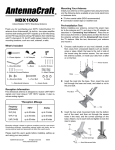
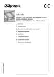
1
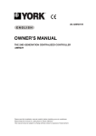
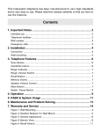
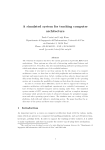
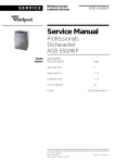
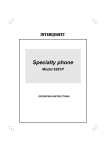
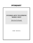
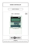
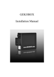
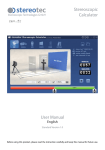
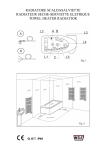
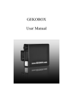
The 2nd-Generation
Centralized Controller for
Outdoor Units: DTCO-UHXRV
Installation & Operation Manual
Please keep this specifications Manual properly.
Read this specifications Manual carefully before
using the equipment.
Table of Contents
Centralized Controller DTCO-UHXRV
Table of Contents
PRESENTATION & PRECAUTIONS....................................................................................... 3
1. INSTALLATION........................................................................................................INST-1
2. USE OF THE EQUIPMENT.......................................................................................OPER-1
- Table of Contents -
Presentation & Precautions
Centralized Controller DTCO-UHXRV
PRESENTATION & PRECAUTIONS
Acknowledgments
Thank you for your confidence in DTCO-UHXRV 2nd Generation Centralized Controller for Outdoor Units
of
“XRV Systems”.
Use of this Specification Manual
This specification Manual describes the installation of Centralized Controller and the conditions of
operating it. For future reference, please keep this Manual properly after the device’s installation and
testing.
Available functions on DTCO-UHXRV device
The functions which DTCO-UHXRV device is able to carry out also depend on the available functions on
PCB of the Outdoor Units which belong to the systems to be controlled.
The Outdoor Units must have on their Control PCB a “NIM” Module (”Network Interface Module”).
Each Centralized Controller DTCO-UHXRV is able to control and monitor up to max. 32 Outdoor Units.
Therefore, through DTCO-UHXRV it is possible the following:
• To monitor the operation of the Outdoor Units that are connected to the signal network, therefore to
immediately display the main operation parameters for each Unit, that is for example: fan speed,
operation state of compressors, state of SV valves, opening of expansion valves (EXV), state of main
4-ways valve (ST1) and auxiliary 4-ways valve (ST2), automatic defrost, oil recovery from refrigerant
circuit, instant energy consumption (kWh), pilot frequency of Inverter compressor, total number of Indoor
Units connected to the Outdoor Unit, temperature on heat exchanger, outside air temperature, outlet
temperature of compressors, current values of compressors.
• To force operation mode to Cooling mode, so as to prevent Users from selecting a different operation
- Presentation & Precautions -
Presentation & Precautions
Centralized Controller DTCO-UHXRV
mode by using the Indoor Units’ remote controllers.
• To allow the consumptions’ recording of each Outdoor Unit, so as to allocate easily and equitably the
energy costs of air-conditioning systems. This function is available only in case of installation of the
Electricity Absorption Detector on each Outdoor Unit whose consumptions you want to record.
• To display the Error Codes referred to eventual Malfunctions and Protection Functions on the Outdoor
Units connected to the Centralized Controller‘s signal network.
Appearance and functions of DTCO-UHXRV device
• This DTCO-UHXRV Centralized Controller is equipped with a LCD display, which is able to display
simultaneously or in sequence a great amount of information.
• The push-button panel is protected by a cover with simplified opening for access to buttons.
• Moreover, on DTCO-UHXRV there is a Red LED, that indicates that the Centralized Controller is
powered by the provided transformer.
For further information and/or eventual explanations
In case of doubt or whatever need referred to the operation of DTCO-UHXRV Centralized Controller,
please contact the Dealer who provided the device and/or the air-conditioning systems.
- Presentation & Precautions -
Part 1: Installation
Centralized Controller DTCO-UHXRV
1. INSTALLATION
Note
In the wiring diagrams in the following pages there is the RS-485 ↔ RS-232 Converter. However, this
component and its wiring are required only in case the Control System is connected to a PC where the
BMS-UHXRV Software Package has been installed.
A PC can manage up to max. 16 DTCO-UHXRV Centralized Controllers and 16 DTC-IHXR Centralized
Controllers; each DTCO-UHXRV can control and monitor up to max. 32 Outdoor Units, while each
DTC-IHXR can control and monitor up to 64 Indoor Units. DTCO-UHXRV & DTC-IHXR Centralized
Controllers on network differ from other controllers for the address (which cannot be duplicated)
assigned to each one; for DTCO-UHXRV, you can assign an address in the range 16~31, while for
DTC-IHXR, you can assign an address in the range 00~15
Safety Precautions
Read carefully the Safety Precautions before installing the DTCO-UHXRV Centralized Controller.
Stated below are important safety issues that must be obeyed.
Safety Precautions are differentiated by the following marks, according to the possible consequences
which may result in case the instructions are not observed.
!
Warning
Means improper handling may lead to personal injury or property loss.
Note
Means improper handling may lead to personal death or severe injury.
Upon completion of the installation, check the correct operation of the DTCO-UHXRV Centralized
Controller by carrying out the Trial Run of the device. Always deliver the User’s Manual to the User, and
recommend him to keep it with care for future reference.
!
Warning
Please entrust the Distributor or the Authorized Technical Service to install the equipment. Installation by
unauthorized persons may lead to imperfect installation which may result in electric shock or fire.
INST-1
Part 1: Installation
Centralized Controller DTCO-UHXRV
To carry out correct installation of DTCO-UHXRV Centralized Controller, carefully observe this Manual.
Improper installation may lead to electric shock or fire.
In case DTCO-UHXRV device is removed and then reinstalled, it is necessary to observe the same
instructions shown in this Manual for first installation. Improper reinstallation may lead to electric shock
or fire.
Do not uninstall DTCO-UHXRV device without the User’s permission. Before removing the equipment, it
is necessary to configure again the Units and the other equipments of the Control System, otherwise the
Units may run abnormally, the wiring may get overheated and lead to fire.
Note
Do not install the equipment in a place where leakage of flammable gas may occur. Once flammable
gases are leaked and left around the Centralized Controller, fire may occur.
Examples of wiring of DTCO-UHXRV in the Control System
(Position of DTCO-UHXRV along the signal lines, as regards the Outdoor Units to be controlled and
monitor. Both wiring diagrams proposed below are correct.) It is reminded that the number max. of
Outdoor Units that can be controlled and monitored by each DTCO-UHXRV is 32.
Example 1
Outdoor Unit
Outdoor Unit
Outdoor Unit
Outdoor Unit
Outdoor Unit
Outdoor Unit
Centralized Controller DTCO-UHXRV
Example 2
Outdoor Unit
Outdoor Unit
Outdoor Unit
Centralized Controller DTCO-UHXRV
INST-2
Outdoor Unit
Outdoor Unit
Outdoor Unit
Part 1: Installation
Centralized Controller DTCO-UHXRV
Packing box list
Check whether the assemblies are complete:
1. Centralized Controller DTCO-UHXRV, with pre-wired power supply cable and bipolar female connector
of proprietary type, quick clutch.
2. Phillips roundheaded metric screws M4 x 25 (3 pcs.), for fixing the Centralized Controller inside an
electric box of commercial type.
3. Phillips roundheaded wood screws M4 x 20 (3 pcs.), for direct and on sight installation of Centralized
Controller on the fixing surface.
4. Phillips roundheaded self-tapping screws M4 x 15 (2 pcs.), for eventual other kinds of fixing (example:
sheet metal surfaces).
5. 120Ω ohmic resistance, pre-wired at both ends, to be installed at the ending and between the contacts
“K1, K2” in the connection terminal block of DTCO-UHXRV (connection to the Outdoor Units to be
controlled).
6, Current transformer for powering of DTCO-UHXRV, with bipolar male connector, quick clutch. Input
voltage: 220V AC. Output voltage: 9.5V DC.
7. This Installation & Operation Manual.
A
BACK VIEW
FRONTAL VIEW
B
• Dimensions of Centralized Controller:
• Distances between fixing holes:
- Height = 120mm.
- A ↔ C = 85mm
- Width = 120mm.
- B ↔ C = 48mm
- Depth = 20mm ~ 33mm.
INST-3
C
Part 1: Installation
Centralized Controller DTCO-UHXRV
M4 x 25
M4 x 15
120Ω
M4 x 20
LENGTH OF CABLE: 1.7 METRES
POWER CONNECTOR
INST-4
Part 1: Installation
Centralized Controller DTCO-UHXRV
Installation assemblies, not included in the packaging (to be purchased on site)
Before starting the installation, please purchase the following assemblies and material on site:
1. 3-core shielded cables, of necessary length and appopriate size according to the length required by
installation, for the connection of DTCO-UHXRV to the Outdoor Units (signal lines “K1, K2, E”) to be
controlled. The recommended min. size is of 1.0 mm2.
2. In case of several DTCO-UHXRV Centralized Controllers and of a PC provided with a BMS-UHXRV
Software package (original software, and specific for “Building Management System”) and corresponding
Hardware (RS-485 ↔ RS-232 Converter): 3-core shielded cables, of necessary length and appropriate size
(the recommended size is of 1.0 mm2) according to the length required by installation, for the connection of
DTCO-UHXRV devices each other (signal lines “F1, F2, E”) and for the connection between the first
DTCO-UHXRV and RS-485 ↔ RS-232 Converter.
3. Embedded or at sight electric boxes, according to the quantity required by installation (depending on the
number of DTCO-UHXRV Centralized Controllers), and provided with screw joints, watertightness.
4. Plastic hard pipes for electric wires, whose total length is able to satisfy installation requirements.
5. Nylon clamps for electric wires, whose quantity is able to satisfy installation requirements.
Connection of DTCO-UHXRV to the power transformer (provided)
1. DTCO-UHXRV is powered by the power transformer included in the packaging.
2. The output voltage of transformer is 9.5V DC. The input voltage of transformer is 220V AC.
3. The length of the output power cable of transformer is of 1.7m. It is recommended not to make junctions on
the cable to extend its length. Therefore, when the installation position of DTCO-UHXRV is selected, it is
necessary to take into consideration the length of cable.
4. At the end of the output cable of transformer, there is a bipolar male connector of proprietary type, quick
clutch. It must be connected to the corresponding female connector, pre-wired on DTCO-UHXRV, as it is
shown in the following page.
5. The clutch between the connectors foresees a security system composed of 2 pressure side tabs,
INST-5
Part 1: Installation
Centralized Controller DTCO-UHXRV
so as to prevent the accidental disconnection of wiring.
Centralized Controller
DTCO-UHXRV
Power transformer
Input: 220V AC / Output: 9.5V DC
2-pole Power Supply Connectors
Addressing of each DTCO-UHXRV, in the signal network
1. Each DTCO-UHXRV Centralized Controller can control up to max. 32 Outdoor Units.
2. On the same signal network, there can be up to max. 16 DTCO-UHXRV Centralized Controllers,
provided that a different address is assigned to each Centralized Controller: the same address must not be
assigned to two different DTCO-UHXRV Centralized Controllers.
3. The addressing (variable from “16” to “31”: the default address is “16”) is carried out by pressing repeatedly
with a pointed article the “ADDRESS” microswitch (see the Figure below), until in the standby screen - down
on the right - the desired address is displayed.
“ADDRESS” microswitch
INST-6
Part 1: Installation
Centralized Controller DTCO-UHXRV
4. Each time “ADDRESS” button is pressed - with a pointed article -, the address assigned to
DTCO-UHXRV increases by steps of one Unit, according to the sequence shown below:
16 → 17 → 18 → 19 → 20 → 21 → 22 → 23 → 24 → 25 → 26 → 27 → 28 → 29 → 30 → 31
Assigned Address = “16” (factory default setting)
Addressing of the Outdoor Units as regards DTCO-UHXRV Centralized Controller
In order that each Outdoor Unit can be correctly recognized in the signal network and controlled by
DTCO-UHXRV, it is necessary that it is previously “addressed” (by the assignation of one number in the
signal network), as regards DTCO-UHXRV.
To that end, on the Control PCB of the Outdoor Unit there are the following hardware assemblies:
• “S2” battery composed of 2 microswitches: each of them can be set to “ON” or to “OFF”, in order to
obtain the 2 only useful combinations for the addressing. The combination of the 2 microswitches bounds
the ends of the addresses’ range which can be assigned by S3 rotary selector (see the following item and
the Table in the following page).
• “S3” rotary selector, with 16 positions, that can be set from “0” to “F”, for the assignation of an address
number to the Outdoor Unit as regards DTCO-UHXRV Centralized Controller for Outdoor Units. If “S3”
rotary selector is used in combination with S2 - battery composed by 2 microswitches - allows to cover
an address range from “00” to “31”.
INST-7
Part 1: Installation
Centralized Controller DTCO-UHXRV
Before using a Centralized Controller for Outdoor Units, and before using BMS-UHXRV software
application, the addressing procedure of the Outdoor Units as regards the Centralized Controller must have
been necessarily completed. Each Outdoor Unit must have a different address as to the other Outdoor
Units controlled by the same DTCO-UHXRV Centralized Controller.
Selectors for the addressing of the Outdoor Unit as regards the Centralized Controller
S2
S3
da “0”
fino a “F”
00 ~ 15
~
S2
S3
Limits of the address range (S2)
da “0”
fino a “F”
~
16 ~ 31
Note.
Whatever combination of “S2” microswitches which is different from those represented in the Table, is
not correct.
INST-8
Part 1: Installation
Centralized Controller DTCO-UHXRV
Basic conditions of installing the Centralized Controller
Please observe the following basic conditions to carry out a professional installation of DTCO-UHXRV:
1. Connect the power transformer to the nearest power socket.
2. Do not lay the power cables of the Outdoor Units by inserting them inside the same plastic hard wire pipe,
used for the signal cables (“K1, K2, E”) (“F1, F2, E”). Insert the power cables and the signal cables in two
different hard wire pipes and keep a distance of at least 0.5 metres between the pipes.
3. The signal cables of DTCO-UHXRV Centralized Controller shall not exceed 1200m.
4. No intermediate joint is allowed for the shielded signal cable. If joints are inevitable, crimp them with the
terminal.
5. After the Centralized Controller is connected to the signal cables, it is no more possible to inspect
insulation between each wire of signal cables.
6. Wiring mode for connection between the Centralized Controller and the “NIM” Module (”Network Interface
Module”) of Outdoor Units to be controlled. On this point, Installers are reminded that the signal lines “K1, K2”
(between DTCO-UHXRV and the nearest Outdoor Unit, and among the Outdoor Units) are polarized,
therefore they should correspond properly at both sides. Do not cross-connect cables (see the Figure below).
The same principles apply to “F1, F2” signal lines between the DTCO-UHXRV Centralized Controllers and
between the first DTCO-UHXRV and the RS-485 ↔ RS-232 Converter - supplied with the BMS-UHXRV
Software Package - for control and monitoring by PC.
• WRONG connection
• CORRECT connection
K1 K2
E
E
E
K1 K2
E
K1 K2
K1 K2
• WRONG connection
• CORRECT correction
F1 F2
E
E
E
F1 F2
E
F1 F2
F1 F2
INST-9
Part 1: Installation
Centralized Controller DTCO-UHXRV
Installation procedure
The installation of DTCO-UHXRV Centralized Controller may take place directly on the fixing surface or
inside a special electric box (embedded or on sight installation).
• The size of the signal wires to be conncected to DTCO-UHXRV depends on the length of the signal lines.
The recommended min. size is of 1.0 mm2. The max. length is of 1200m.
• Lay the Centralized Controller’s cables inside a plastic hard wire pipe, of appropriate dimension. Never lay
in the same pipe the signal cables and the power cables.
• Remove the frontal panel of DTCO-UHXRV by inserting the point of a flathead screwdriver in the hollows
on the upper part of the device. Slightly rotate to separate the frontal panel from the back cover of
DTCO-UHXRV (see the Figure below).
For the details about the removal of the frontal panel and the connections to the terminal blocks, please
refer to the Figures below and to the following page.
Opening of the device & installation assemblies
Hollows on the upper part
(insert a screwdriver for opening)
Back cover
Front cover
Display LCD
Push-button panel
Terminal bock for the signal lines
(leave a space for cables)
Lid
Mounting screws (M4 x 25) on the electric box,
or fixing screws (M4 x 20)
Notes.
1. The central Figure shows the position of the 3 fixing holes, on the back cover.
2. For the le dimensions of DTCO-UHXRV and the distances between the fixing holes, please refer
to the Figures on page INST-3.
INST-10
Part 1: Installation
Centralized Controller DTCO-UHXRV
Total view of DTCO-UHXRV’s connections
Signal Lines
Power Supply
Terminal block for the connection of signal lines (on the back of DTCO-UHXRV)
K1, K2, E:
F1, F2, E:
Communication lines with other eventual
DTCO-UHXRV Centralized Controller and
with the PC (connection to RS-485 ↔
RS-232
Converter,
provided
with
BMS-UHXRV) that manages the Control
System.
INST-11
Communication lines of DTCO-UHXRV
with the Outdoor Units that are equipped
with a “Network Interface Module” (“NIM”).
Part 1: Installation
Centralized Controller DTCO-UHXRV
Wiring 1: DTCO-UHXRV Centralized Controllers for Outdoor Units + DTA-IHXR Time Wattmeter
Outdoor Units
Notes:
1. The power lines of each Outdoor Unit must be connected at first to DTA-IHXR Digital Ammeter,
and then to the power terminal block of Outdoor Unit. The cable size for the power lines depends
on the capacity of the Outdoor Unit.
2. Each Centralized Controller for Outdoor Units can control up to 32 Outdoor Units.
120Ω
AB CN
9
O A
AB CN
AB CN
6
Power supply
3
6
9
4
7
4
7
380~415V,
3Ph, 50Hz
1
3
4
7
N
6
9
4
7
AB C
N
380~415V,
3Ph, 50Hz
N
380~415V,
3Ph, 50Hz
Outdoor Units
120Ω
AB CN
3
6
9
3
4
7
4
7
N
4
N
L N
Power Supply(220V)
K1 K2 E F2 F1
Connections among O.U. Connections Control Network
Centralized Controller
No.16 for Outdoor Units
(DTCO-UHXRV)
AB CN
10
3
7
6
9
10
I II
DTA-IHXR
1
AB C
380~415V,
3Ph, 50Hz
O A
AB CN
DTA-IHXR
1
AB C
380~415V,
3Ph, 50Hz
9
Power supply
I II
DTA-IHXR
1
AB C
6
I II
DTA-IHXR
1
O A
AB CN
10
I II
K1 K2 E
E
H2
H1
E
H2
H1
AB CN
AB CN
10
K1 K2 E
Power supply
Secondary
Outdoor Unit (1)
O A
AB CN
AB CN
9
Power supply
Main Outdoor
Unit (No.X)
K1 K2 E
E
H2
H1
E
H2
H1
O A
Secondary
Outdoor Unit (1)
Main Outdoor
Unit (No.10)
K1 K2 E
6
Centralized Controller
No.1 for Outdoor Units
(DTCO-UHXRV)
10
120Ω
3
Connections among O.U. Connections Control Network
I II
Notes:
1. The power lines of each Outdoor Unit must be connected at first to DTA-IHXR Digital Ammeter,
and then to the power terminal block of Outdoor Unit. The cable size for power lines depends on the
capacity of the Outdoor Unit.
2. Each Centralized Controller for Outdoor Units can control up to 32 Outdoor Units.
Power supply
K1 K2 E F2 F1
DTA-IHXR
1
AB C
380~415V,
3Ph, 50Hz
L N
Power Supply(220V)
AB CN
10
DTA-IHXR
AB C
N
9
O A
I II
DTA-IHXR
1
AB C
6
I II
DTA-IHXR
1
3
Power supply
AB CN
AB CN
10
I II
K1 K2 E
E
H2
H1
E
H2
H1
O A
AB CN
AB CN
10
K1 K2 E
Power supply
Secondary
Outdoor Unit (1)
K1 K2 E
E
H2
H1
E
H2
H1
O A
Main Outdoor
Unit (No.2)
K1 K2 E
Power supply
Secondary
Outdoor Unit (1)
Main Outdoor
Unit (No.1)
120Ω
3
To RS-485 ↔ RS-232 Converter
(and to other Centralized Controllers)
4
7
AB C
N
380~415V,
3Ph, 50Hz
N
380~415V,
3Ph, 50Hz
Notes.
1. The signal lines “P, Q, E” (between the Indoor Units and the Outdoor Unit), “X, Y, E” (among the Indoor Units, and
between the Indoor Units and the Centralized Controller for Indoor Units), “H1, H2, E” (among Outdoor Units installed in
combination each other), “K1, K2, E” (among the Outdoor Units, and between the Outdoor Units and the Centralized
Controller for Outdoor Units), “F1, F2, E” (between the Personal Computer for “Building Management System”, and the
Centralized Controllers for Indoor/Outdoor Units), require the use of shielded cables having a min. size of 1.0mm2. All
wiring has a polarity that must correspond properly. During installation, do not cross-connect cables. The max. allowed
length for each signal line is of 1000m.
2. For the survey of the electric consumptions of a given Outdoor Unit, it is necessary a further connection (“O”, “A” lines)
between the Outdoor Unit and the optional device DTA-IHXR (“Digital Ammeter”), specific only for that Outdoor Unit.
3. Each Personal Computer, through BMS-UHXRV Package, can manage up to max. 16 Centralized Controller for Outdoor
Units. Each Centralized Controller for Outdoor Units can control up to 32 Outdoor Units.
4. The parallel installation of 120Ω resistances at each end of signal lines (see the diagram above) is no more strictly
required, as in the meantime the capacity of anti-interference of the integrated control firmware in the Units (in the
EEPROM) has improved.
INST-12
Part 1: Installation
Centralized Controller DTCO-UHXRV
Wiring 2: DTC-IHXR Centralized Controllers for Outdoor Units and connection to Personal Computer
Wiring between the Indoor Units and the Centralized Controllers
Serial Connector RS232
(to be connected to PC)
120Ω
; < (
PCB
RS485 ↔ RS232 Converter
(supplied with BMS-UHXRV)
; < (
PCB
NFM
Indoor Unit No. 1
; < (
PCB
NFM
Indoor Unit No. 2
NFM
Indoor Unit No. 3
F1 F1 F2 F2 E
120Ω
To other Centralized Controllers
N
L
Alimentazione (220V)
per C.C. DTC-IHXR
E
F2
F1
Al personal Computer e
ad altri C.C. DTC-IHXR
E
Y
; < (
X
PCB
Alle Unità Interne da controllare
; < (
PCB
NFM
Indoor Unit No. 64
NFM
Indoor Unit No. 63
; < (
PCB
NFM
Indoor Unit No. 62
Wired Controller
Centralized Controller
No.1 for Indoor Units
120Ω
; < (
PCB
; < (
PCB
NFM
Indoor Unit No. 1
; < (
PCB
NFM
Indoor Unit No. 2
NFM
Indoor Unit No. 3
120Ω
N
L
Alimentazione (220V)
per C.C. DTC-IHXR
E
F2
F1
Al personal Computer e
ad altri C.C. DTC-IHXR
E
Y
; < (
X
Alle Unità Interne da controllare
PCB
NFM
Indoor Unit No. 64
; < (
PCB
NFM
Indoor Unit No. 63
; < (
PCB
NFM
Indoor Unit No. 62
Wired Controller
Centralized Controller
No.16 for Indoor Units
Notes:
1. The signal lines: “X, Y, E” (between the Indoor Units, and between the Indoor Units and the Centralized Controller for
Indoor Units), “F1, F2, E” (between the PC for “Building Management System”, and the Centralized Controllers for
Indoor/Outdoor Units), require the use of shielded cables with min. size of 1.0mm2. Both sides of these wires should
correspond properly. During installation, do not cross-connect cables. The max. allowed length for each signal line is of
1200m.
2. Each Personal Computer, through the BMS-UHXRV Package, can manage up to max. 16 Centralized Controllers for
Indoor Units. Each Centralized Controller for Indoor Units can control up to max. 64 Indoor Units.
3. The parallel installation of 120Ω resistances at each end of signal lines (see the diagram above) is no more strictly
required, as in the meantime the anti-interference capacity of the control firmware inside Units (in the EEPROM) has been
improved.
INST-13
Part 2: Use of the Equipment
Centralized Controller DTCO-UHXRV
2. USE OF THE EQUIPMENT
Operative conditions for the use of DTCO-UHXRV device
It is recommended to use the DTCO-UHXRV equipment only if there are the following requirements for its
correct operation:
1. Power supply specifications of the device. Input voltage: 1-Phase, 220 ~ 242V AC.
Input power supply frequency: 50/60Hz.
2. Operating environment temperature for a correct operation of the device:
- Temperature range: -15°C ~ 43°C.
- RH conditions in the installation site: 40% ~ 90%.
Organization of the information contained in this Manual
In the following pages, the following matters will be treated in depth:
(1) Composition & Structure of Network Control System for air-conditioning installations.
(2) Keywords & General Function Description.
(3) Detailed description of electric control functions of Centralized Controller.
(4) Tables of Error and Protection Codes shown by DTCO-UHXRV’s display.
(4) Corresponding rules for Electromagnetic Compatibility (EMC) & Safety.
OPER-1
Part 2: Use of the Equipment
Centralized Controller DTCO-UHXRV
(1) Composition & Structure of Network Control System for air-conditioning installations.
1. The DTC-IHXR device allows to carry out the Centralized Control of the operation and Monitoring of
Indoor Units (query about some operating parameters, regular operating status, malfunctions, etc.),
provided that DTC-IHXR and the Indoor Units are connected each other in a signal network.
2. The DTC-IHXR Centralized Controller can be connected to a PC (which must be equipped by a
special Software), and by the PC it may interface with a Gateway (Lonworks® or BACnet®), thus
belonging to a “BMS” System (“Building Management System”): therefore, the DTC-IHXR device carries
out the Centralized Control and the Monitoring of the air conditioners.
In this way, the air conditioners can be remote controlled, by reaching the PC and consequently the
Control System even outside the building, through a WAN (“Wide Area Network”, therefore also by
connecting to the PC by Internet), thus exceeding the limits set by the signal lines’ max. length.
3. The interactive mode between the “Master” device ↔ “Slave” device - which occurs when there is a
hierarchy between hardware components - also applies to the communication between the DTC-IHXR
Centralized Controller and the Indoor Units, and between the PC and the DTC-IHXR.
In particular, inside the LAN (“Local Area Network”) made up of the DTC-IHXR and of the Indoor Units,
the DTC-IHXR device is the Primary Equipment (“Master”), while the Indoor Units represent the
Secondary Equipment (“Slave”). In the same way, inside the LAN (“Local Area Network”) made up of the
PC and of the DTC-IHXR Centralized Controller, the PC is the Primary Equipment (“Master”), while the
DTC-IHXR device is the Secondary Equipment (“Slave”).
The Figure in the following page is a simplified representation of the Control System previously
described.
If one or several Indoor Units do not have a “X, Y, E” terminal block for the connection to the Control
System, that is if the PCB does not have a “NIM” Module (“Network Interface Module”), it will be
necessary to purchase separately this network interface, which is available as optional accessory
(NIM-GRH).
OPER-2
Part 2: Use of the Equipment
Centralized Controller DTCO-UHXRV
Overall view of Control System
Indoor Units
Network Interface
Centralized Controller DTC-IHXR
Personal Computer
(with BMS-UHXRV)
Note: The Network Interface may be
already integrated on the Indoor Unit’s
PCB, otherwise it must be bought
separately as an optional accessory
(NIM-GRH).
World Wide Web
(Internet)
Up to max. 64 Indoor Units each DTC-IHXR
Up to max. 16 DTC-IHXR on the signal network
OPER-3
Part 2: Use of the Equipment
Centralized Controller DTCO-UHXRV
(2) Keywords & general function description.
2.1 What happens when DTCO-UHXRV is powered.
When DTCO-UHXRV is powered and the current transformer (that functions as a power supplier)
is connected to the network, for 3 seconds the display LCD of DTCO-UHXRV shows all indications
that can be displayed.
At the end of this interval, standby’s screen appears, which displays the following information:
- Number of “Modules”, that is of Outdoor Units, and number of Installations (in case of Outdoor
Units that are installed in combination each other, each installation is composed of min. 2
“Modules” up to max. 4 “Modules”) which are powered and connected (“On line” is displayed) to the
Centralized Controller’s signal network and which are recognized by DTCO-UHXRV (necessary
condition: the Outdoor Units must be expressly and correctly addressed as regards
DTCO-UHXRV). Concerning the addressing procedure of Outdoor Units, please refer to “Part 1:
Installation” of this Manual.
- Number of address (below on the right) assigned to DTCO-UHXRV.
2.2 Address setting method of DTCO-UHXRV, in case of several devices on the same signal
network.
In the presence of a Personal Computer equipped with a special Software (and eventually
interfaced by a Gateway Lonworks® or BACnet® to control networks of another kind), on the same
signal network there can be up to max. 16 DTCO-UHXRV equipments. In the structure for the
centralized control of the Outdoor Units, each DTCO-UHXRV is usually dedicated to the Outdoor
Units that are installed in a given area of the building. An address is assigned to each
DTCO-UHXRV - in the range 16 ~ 31 - to distinguish it from the other DTCO-UHXRV equipments;
the address setting method is carried out as it has been previously described in “Part 1: Installation”
of this Manual.
2.3 LED LED (status LED) on DTCO-UHXRV.
If the Red LED is ON, this means that DTCO-UHXRV is powered by the electric network, through
the special current transformer.
OPER-4
Part 2: Use of the Equipment
Centralized Controller DTCO-UHXRV
2.4 Lock of DTCO-UHXRV’s buttons.
In order to avoid to press unintentionally any button on DTCO-UHXRV Centralized Controller, it is
possible to lock the push-button panel, by pressing with a pointed article the special “LOCK” button when
standby’s screen is displayed. If lock function is operating, the indicator
To cancel lock function, press “LOCK” button again. The indicator
is displayed.
will disappear from the display.
2.5 Lock of Cooling mode by DTCO-UHXRV.
If a special option is activated (called “Forced Cooling”), it is possible to prevent from selecting - by the
Indoor Units’ remote controller - any operation mode incompatible with the Cooling mode. If this
happens, the Indoor Unit will work in Fan only mode.
However, if “Forced Cooling” option is activated on DTCO-UHXRV, the operation mode of one or several
Indoor Units can be changed by using a DTC-IHXR Centralized Controller for Indoor Units (present on
the signal network). In this case, the operation settings that have been selected by DTC-IHXR take the
priority over “Forced Cooling” function activated on DTCO-UHXRV.
2.6 Display of Outdoor Unit‘s instant consumption by DTCO-UHXRV.
In “QUERY” mode (see further on), among the parameters that can be displayed on each Outdoor Unit
controlled by DTCO-UHXRV, there is also the instant electric consumption, expressed in kWh.
This parameter can be displayed if an Electrical Input Detector DTA-IHXR specific for that Outdoor Unit
is installed.
OPER-5
“SET” button
“QUERY” button
“MODE” button
“ADDRESS” button
“OK” button
“LOCK” button
“PREVIOUS” & “NEXT” buttons
PUSH-BUTTON PANEL OF DTCO-UHXRV CENTRALIZED CONTROLLER
“PAGE UP/DOWN” buttons
Centralized Controller DTCO-UHXRV
Part 2: Use of the Equipment
(3) Detailed specification of parts & functions of the equipment.
3.1 Outline of DTCO-UHXRV’s buttons-
OPER-6
Part 2: Use of the Equipment
Centralized Controller DTCO-UHXRV
“QUERY” button
If you press “QUERY” button, you can enter “QUERY” mode about the operating state of the
controlled Outdoor Units.
As default setting, the information are displayed about the Outdoor Unit “On line” (that is powered,
connected to the signal network of Centralized Controller, and correctly addressed as regards
DTCO-UHXRV) which has the lower number among those that have been assigned according to
the control by the Centralized Controller.
“PREVIOUS” button
In “QUERY” mode, if you press “PREVIOUS” button, it is possible to display the operating
parameters of the Outdoor Unit “On line” having the address number immediately previous as
regards the Outdoor Unit currently displayed.
If the Outdoor Unit currently displayed has the lower number among all Outdoor Units controlled by
DTCO-UHXRV, if you press “PREVIOUS” button, the operating parameters of the Outdoor Unit
having the higher number among all the Outdoor Units controlled by DTCO-UHXRV are displayed.
“NEXT” button
In “QUERY” mode, if you press “NEXT”, it is possible to display the operating parameters of the
Outdoor Unit “On line” having the address number immediately following as regards the Outdoor
Unit currently displayed.
If the Outdoor Unit currently displayed has the higher number among all Outdoor Units controlled by
DTCO-UHXRV, if you press “NEXT” button, the operating parameters of the Outdoor Unit having the
lower number among all the Outdoor Units controlled by DTCO-UHXRV are displayed.
“PAGE UP” button
In “QUERY” mode, if you press “PAGE UP” button, it is possible to get to the screen that displays
the operating parameter immediately previous, as regards the parameter currently displayed,
OPER-7
Part 2: Use of the Equipment
Centralized Controller DTCO-UHXRV
for the Outdoor Unit previously selected.
If the operating parameter currently displayed is the first in the list of the displayed parameters, if
you press “PAGE UP” button, the last operating parameter in the list of the displayed parameters for
the Outdoor Unit previously selected is displayed.
“PAGE DOWN” button
In “QUERY” mode, if you press “PAGE DOWN” button, it is possible to get to the screen that
displays the operating parameter immediately following, as regards the parameter currently
displayed, for the Outdoor Unit previously selected.
If the operating parameter currently displayed is the last in the list of the displayed parameters, if
you press “PAGE DOWN” button, the first parameter in the list of the displayed parameters for the
Outdoor Unit previously selected is displayed.
“SET” button
If the equipment is not in “SET” mode yet, if you press “SET” button, you can select “SET” mode for
setting the available options for the operation of the Outdoor Units “On line” controlled by
DTCO-UHXRV.
“MODE” button
If the equipment is in “SET” mode, by pressing “MODE” button you can switch over - in a cyclic way
- between the “Forced Cooling” option
(that is: impossibilty to set, by the remote controllers
of the Indoor Units which belong to the system, an operation mode incompatible with the Cooling
mode) and the option “
” (that is: no limit to the operation mode that can be selected by the
Indoor Units’ remote controllers, except the restrictions which arise from the control logic inside the
system).
“OK” button
After selecting, by “MODE” button (see above), between the option “Forced Cooling”
option “
”, it will be necessary to confirm the selection by pressing “OK” button.
OPER-8
and the
Part 2: Use of the Equipment
Centralized Controller DTCO-UHXRV
In case of successful operation, after 4 seconds, in the lower part and on the right of the display the
indication
is displayed.
In case of unsuccessful operation, after 4 seconds, in the lower part and on the right of the display the
indication
is displayed.
“LOCK” button
In order to avoid to press unintentionally any button on DTCO-UHXRV Centralized Controller, it is
possible to lock the push-button panel, by pressing with a pointed article “LOCK” button when standby
screen is displayed. If lock function is operating, the indicator
To cancel lock function, press “LOCK” button again; the indicator
is displayed.
will disappear from the display.
“ADDRESS” button
As it has been already seen in “Part 1: Installation”, on the same signal network there can be up to max.
16 DTCO-UHXRV Centralized Controllers, provided that only one address is assigned to each
Centralized Controller (the same address must not be assigned to one or several DTCO-UHXRV
Centralized Controllers).
The address setting method (variable from “16” to “31”: the default address is “16”) can be carried out by
pressing repeatedly this microswitch (“ADDRESS”), until in the lower part and on the right of the display’s
screen, the desired address number is displayed.
OPER-9
OPER-10
the displayed information will concern the actual operating conditions of the installations.
The Figure shows all indicators and information that LCD is able to display. During the use of DTCO-UHXRV Centralized Controller,
Note.
DISPLAY OF DTCO-UHXRV CENTRALIZED CONTROLLER
Centralized Controller DTCO-UHXRV
Part 2: Use of the Equipment
3.2 Outline of indicators on DTCO-UHXRV’s display.
Part 2: Use of the Equipment
Centralized Controller DTCO-UHXRV
3.2.1 Indicators that can be displayed on ALL screens of display
This indicator is displayed only if DTCO-UHXRV Centralized Controller is connected to a
Personal Computer and eventually to a Gateway. If the connection is interrupted, the indicator
will disappear from the display after 20 seconds.
This indicator is displayed only if DTCO-UHXRV Centralized Controller is connected to the
Outdoor Units (through the “NIM”, that is “Network Interface Module”; the module is integrated
on the Control PCB of each Outdoor Unit). If the connection is interrupted, the indicator will
disappear from the display after 20 seconds.
This indicator is displayed in a dynamic and cyclic way (gradual switching on of the indicator,
followed by full switching off, and so on), to indicate that communication between
DTCO-UHXRV Centralized Controller and “NIM” Modules (see above) of the Outdoor Units
occurs regularly.
This indicator is displayed if Lock function of buttons on DTCO-UHXRV Centralized Controller
is operating, that is after pressing “LOCK” button. The indicator disappears from the display if
the function is cancelled, that is after pressing “LOCK” button again.
OPER-11
Part 2: Use of the Equipment
Centralized Controller DTCO-UHXRV
3.2.2 Indicators in “STANDBY” Page Display
This indicator refers to the total number of “Modules” (in case of an installation
composed of several Outdoor Units that are installed in combination each other,
from a min. of 2 up to max. 4 Units, the indicator refers to each Outdoor Unit that
belongs to the installation) which are “On line”, that is are powered, connected to
the signal network of DTCO-UHXRV and correctly “addressed” for being controlled
by the Centralized Controller.
This indicator refers to the total number of installations (where each installation
may also be composed of several Outdoor Units, called “Modules”, installed in
combination each other) which are “On line”, that is are powered and connected to
the signal network of DTCO-UHXRV, and where each Outdoor Unit of the
installation is correctly “addressed” for being controlled by the Centralized
Controlller.
Display of the address number assigned to DTCO-UHXRV, in “STANDBY”
In the lower part and on the right of “STANDBY” page
display, as it is shown in the next photo, it is also
displayed
Indirizzo assegnato = “16” (impostazione di fabbrica)
the
address
number
assigned
to
DTCO-UHXRV in the signal network, for distinguishing
it from other Centralized Controller, if they are
available.
As it has already shown previously, the address number assigned to DTCO-UHXRV in the signal
network can be modified (in the range from “16” to “31”) by pressing repeatedly the “ADDRESS”
button on the equipment, until the display shows the desired address number. The necessary
condition is that DTCO-UHXRV is powered (Red LED: ON).
OPER-12
Part 2: Use of the Equipment
Centralized Controller DTCO-UHXRV
3.2.3 Indicators displayed in “SET” Page Display
If this indicator is ON, this means that “SET” button has previously been pressed, and that the
Centralized Controller is now in “SET” mode.
This indicator refers to the address number of “Module” (in case of an installation
composed of several Outdoor Units installed in combination each other, from a min. of
2 up to max. 4 Units, the indicator refers to each Outdoor Unit that belongs to the
installation) which is currently selected, among the Modules that are “On line”.
This indicator refers to the address of the Main Outdoor Unit in the Installation (in case
of an installation composed of several Outdoor Units, calles “Modules”, installed in
combination each other) which is currently selected among the Outdoor Units that are
“On line”.
Note.
If you press “PREVIOUS” or “NEXT” button, it is possible to scroll respectively up and down the addresses of
Outdoor Units’ “Modules” to which the settings available on the Centralized Controller can be applied.
Example of possible setting in “SET” Mode
If the equipment is in “SET” mode, by pressing “MODE” button you can change over - in a
ciclic way - between the “Forced Cooling” option
(that is: impossibility to set, by the
remote controllers of the Indoor Units which belong to the installation, an operation mode
incompatible with Cooling mode) and the option “
” (that is: no limit to the operation mode
that can be selected by the Indoor Units’ remote controllers, except the restrictions which arise
from the control logic inside the system).
After selecting, by “MODE” button, between “Forced Cooling” option
“
”, it will be necessary to confirm the selection by pressing “OK” button.
OPER-13
and the option
Part 2: Use of the Equipment
Centralized Controller DTCO-UHXRV
If the operation is successful, in the lower part and on the right of the display, the indication
will be displayed after 4 seconds.
If the operation is unsuccessful, the indication
will be displayed
after 4 seconds.
Note.
• The default page display of DTCO-UHXRV is “STANDBY” screen.
If the Centralized Controller is in “SET” Mode (Setting) and no button is pressed for about 30 seconds,
“STANDBY” screen is displayed again.
OPER-14
Part 2: Use of the Equipment
Centralized Controller DTCO-UHXRV
3.2.4 Indicators displayed in “QUERY” Page Display
If this indicator is ON, this means that “QUERY” button has been previously pressed,
and that the Centralized Controller is now in “QUERY” mode.
This indicator refers to the address number of the “Module” (in case of an installation
composed of several Outdoor Units installed in combination each other, from a min. of
2 up to max. 4 Units, the indicator refers to each Outdoor Unit that belongs to the
installation) which is currently selected, among the “Modules” that are “On line”.
This indicator refers to the address of the Main Outdoor Unit of the installation (in case
of an installation composed of several Outdoor Units, called “Modules”, installed in
combination each other) which is currently selected among the Outdoor Units that are
“On line”.
By pressing “PREVIOUS” or “NEXT” button, it is possible to switch over respectively
up and down the addresses of the Outdoor Units “Modules” for which the query of the
operating parameters can be carried out.
This symbol indicates that the current operation mode of the system is the Cooling
mode.
This symbol indicates that the current operation mode of the system is the Heating
mode.
This symbol indicates that the current operation mode of the system is “OFF”, that is
the compressor is not operating.
OPER-15
Part 2: Use of the Equipment
Centralized Controller DTCO-UHXRV
This indicator is displayed when Lock function in Cooling mode is operating, for one or
all Outdoor Units controlled by DTCO-UHXRV Centralized Controller. The indicator
disappear from the display when Lock function is no more operating.
This indicator is displayed when Lock function in Heating mode is operating, for one or
all Outdoor Units controlled by DTCO-UHXRV Centralized Controller. The indicator
disappears from the display when Lock function is no more operating.
This indicator refers to fan speed on the selected Outdoor Unit. In this case, outdoor
fan works at “LOW” speed.
This indicator refers to fan speed on the selected Outdoor Unit. In this case, outdoor
fan works at “MIDDLE” speed.
This indicator refers to fan speed on the selected Outdoor Unit. In this case, fan speed
works at “HIGH” speed.
These indicators display the number of compressors which are operating now.
These indicators display the number of soleinoid valves (“SV1 ~ 6”) which are
ON.
If this indicator is ON, this means that the main 4-ways valve (“ST1”) is on the position
for operation in Heating mode.
If this indicator is ON, this means that the Outdoor Unit’s auxiliary 4-way valve (“ST2”)
is on the position for operation in Cooling mode in conditions of partial load.
OPER-16
Part 2: Use of the Equipment
Centralized Controller DTCO-UHXRV
If this indicator is ON, this means that the automatic defrosting is in progress (reversal
of refrigerant cycle from Heat to Cool).
If this indicator is ON, this means that the procedure of compressors’ oil recovery from
the refrigerant circuit is in progress.
3.2.5 Indications referred to the operating parameters in “QUERY” Page Display
As it has already shown previously, by pressing “PREVIOUS” or “NEXT” button on DTCO-UHXRV, it
is possible to switch over respectively up and down the addresses of the Outdoor Units’ “Modules” for
which the query of the operating parameters can be carried out.
After selecting the Outdoor Unit‘s “Module” for which the query can be carried out, the first page of the
operating parameters that can be displayed will appear.
In order to change over from one page to the following page or to the previous page,
press respectively “PAGE UP” button (“Previous Page”) and “PAGE DOWN” button
(“Following Page”).
•Page 0 of operating parameters.
If an Electrical Input Detector DTA-IHXR is connected to the Outdoor Unit to
be queried, this page displays the information about the Outdoor Unit’s
electric consumption, expressed in KWh.
•Page 1 of operating parameters.
This page displays the pilot frequency value of Inverter compressor on the
selected Outdoor Unit, expressed in Hertz (Hz).
OPER-17
Part 2: Use of the Equipment
Centralized Controller DTCO-UHXRV
•Page 2 of operating parameters.
This page displays the total number of the Indoor Units “On line”, connected
to the installations controlled by DTCO-UHXRV Centralized Controller.
•Page 3 of operating parameters.
This page displays “T3” temperature (temperature on heat
exchanger), detected by the special sensor on the selected Outdoor
Unit, and expressed in °C.
•Page 4 of operating parameters.
This page displays “T4” temperature (outside air temperature)
detected by the special sensor on the selected Outdoor Unit, and
expressed in °C.
•Page 5 of operating parameters.
This page displays the temperature value detected by “T6” sensor where it is available - , and expressed in °C.
In
“XRV Systems”, this temperature sensor is not
available on the Outdoor Units, so the display will show the indication
on the left (- - -).
•Page 6 of operating parameters.
This page displays the outlet temperature value which is detected on
“Compressor 1” (Inverter compressor), and expressed in °C.
OPER-18
Part 2: Use of the Equipment
Centralized Controller DTCO-UHXRV
•Page 7 of operating parameters.
This page displays the outlet temperature value which is detected on
“Compressor 2” (On/Off compressor), and expressed in °C.
•Page 8 of operating parameters.
This page displays the outlet temperature value which is detected on
“Compressor 3” (On/Off compressor), and expressed in °C.
•Page 9 of operating parameters.
This page displays the input current value of “Compressor 1” (Inverter
compressor), expressed in Ampères (A).
•Page 10 of operating parameters.
This page displays the input current value of “Compressor 2” (On/Off
compressor), expressed in Ampères (A).
•Page 11 of operating parameters.
This page displays the input current value of “Compressor 3” (ON/Off
compressor), expressed in Ampères (A).
•Page 12 of operating parameters.
On
“XRV Systems”, this parameter is not available,
so the display will show the indication on the left (- - -).
OPER-19
Part 2: Use of the Equipment
Centralized Controller DTCO-UHXRV
•Page 13 of operating parameters.
This page displays the opening angle of the electronic expansion
valve “EXV1” on the selected Outdoor Unit.
•Page 14 of operating parameters.
This page displays the opening angle of the electronic expansion
valve “EXV2” on the selected Outdoor Unit.
•Page 15 of operating parameters.
This page displays the Error Code referred to the most recent
malfunction which is detected on the selected Outdoor Unit.
or
If there are no malfunctions, the display shows the indication on the
left (- -).
•Page 16 of operating parameters.
This page displays the Protection Code referred to the intervention of
the most recent protection function on the selected Outdoor Unit.
If there is no intervention of protection functions, the display shows the
indicatio on the left (- -).
Notes.
1. The default page display of DTCO-UHXRV is “STANDBY” screen.
If the Centralized Controller is in “QUERY” Mode, and no button is pressed for about 30 seconds,
OPER-20
Part 2: Use of the Equipment
Centralized Controller DTCO-UHXRV
the display will show “STANDBY” screen again.
2. At each query of the Operating Parameters, in “QUERY” screen the first operating parameter will be
the last operating parameter that was analyzed during the previous query.
OPER-21
Part 2: Use of the Equipment
Centralized Controller DTCO-UHXRV
(4) Tables of Error Codes & Protection Codes displayed on DTCO-UHXRV.
• Table of Error Codes
Code
Malfunction Contents
EF
Other kinds of malfunction (besides the malfunctions below).
E4
Malfunction of temperature sensor T4 (outdoor air temperature).
E3
Malfunction of temperature sensor T3 (Outdoor Unit’s heat exchanger).
E2
Malfunction of temperature sensor on Inverter compressor’s discharge pipe.
E1
Phase order error or phase loss.
E0
Fault of communication between Outdoor Units (in combination each other).
H3
Malfunction caused by a transitory increase in number of the connected Outdoor
Units in combination (displayed only on Main Outdoor Unit).
H2
Malfunction caused by a transitory reduction in number of the connected Outdoor
Units in combination (displayed only on Main Outdoor Unit).
H1
Fault of communication between the integrated control circuit for network connection
and the integrated circuit for System Control.
• Table of Protection Codes
Code
Protection Contents
PF
Other kinds of malfunctions (besides the malfunctions below).
PE
Procedure activation for oil balance between compressors.
PD
Procedure activation for oil return from refrigerant circuit.
PA
Intervention of a protection function during automatic defrosting.
P8
Compressor Current 3rd Protection (On/Off compressor).
P7
Compressor Current 2nd Protection (On/Off compressor).
P5
Outdoor Unit’s heat exchanger High Temperature Protection (in Cooling mode).
P4
Discharge Pipe High Temperature Protection (on On/Off compressor).
P3
Compressor Current 1st Protection (Inverter compressor).
P2
Discharge Low-pressure Protection.
P1
Discharge High-pressure Protection.
P0
Inverter Compressor High Temperature Protection.
OPER-22
Part 2: Use of the Equipment
Centralized Controller DTCO-UHXRV
(4) Regulations for Electromagnetic Compatibility and Safety.
1. This DTCO-UHXRV Centralized Controller respects the Regulations for Electromagnetic Compatibility
(EMC), Low Voltage Directive (LVD), and conforms with CE Standards (see CE Declaration of
Conformity, in the following page).
2. This DTCO-UHXRV Centralized Controller respects the Regulations on the Safety of Electric
Equipments: GB4706.32-2004 and GB/T7725-2004.
OPER-23
Declaration
Centralized Controller DTCO-UHXRV
DECLARATION OF CONFORMITY
We
Srl - 14, Via della Salute - 40132 Bologna - Italy
DECLARE UNDER OUR SOLE RESPONSIBILITY
that
Product “DTCO-UHXRV Centralized Controller”
conforms to the following Directives:
• Electromagnetic Compatibility Directive EMC 2004/108/EC.
• Low Voltage Directive LVD 2006/95/EC.
• Harmonized Rules:
EN55014-1:2000+A1:2001+A2:2002
EN61000-3-2:2000, EN61000-3-3:1995+A1:2001
EN55014-2:1997+A1:2001 (Category II)
EN60335-2-40:2003+A11:2004
EN50336:2003.
-
Declaration -
Notes
Centralized Controller DTCO-UHXRV
Notes
Notes-1
Notes
Centralized Controller DTCO-UHXRV
Notes
Notes-2
HOKKAIDO Srl
14, Via della Salute - 40132 Bologna - Italy
Ph. +39.051.41.33.111 Fax +39.051.41.33.146
www.hokkaido.eu
Due to on-going technological development of Products by the Manufacturer, we reserve the right to vary
the technical specifications at any time and without notice.