1
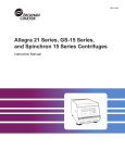
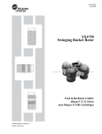
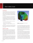
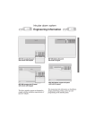
GX-IM-5
Allegra® X-12 Series
Centrifuges
Instruction Manual
Symbol
Symbol
Symbole
Símbolo
Simbolo
Title
/
Titel
/
Titre
/
Titulo
/
Titolo
Dangerous voltage
Gefährliche elektrische Spannung
Courant haute tension
Voltaje peligroso
Pericolo: alta tensione
!
Attention, consult accompanying documents
Achtung! Begleitpapiere beachten!
Attention, consulter les documents joints
Atención, consulte los documentos adjuntos
Attenzione: consultare le informazioni allegate
On (power)
Ein (Netzverbindung)
Marche (mise sous tension)
Encendido
Acceso (sotto tensione)
Off (power)
Aus (Netzverbindung)
Arrêt (mise hors tension)
Apagado
Spento (fuori tensione)
Protective earth (ground)
Schutzleiteranschluß
Liaison à la terre
Puesta a tierra de protección
Collegamento di protezione a terra
Earth (ground)
Erde
Terre
Tierra
Scarica a terra
/
/
!
SAFETY NOTICE
This safety notice summarizes information basic to the safe operation of the equipment
described in this manual. The international symbol displayed above is a reminder that all
safety instructions should be read and understood before installation, operation, maintenance, or repair of this centrifuge. When you see the symbol on other pages, pay special
attention to the safety information presented. Observance of safety precautions will also
help to avoid actions that could damage or adversely affect the performance of the
centrifuge.
Safety During Installation and/or Maintenance
This centrifuge weighs 121 kg (267 lb). Do not attempt to lift or move it without
assistance.
Any servicing of this equipment that requires removal of any covers can expose parts that
involve the risk of electric shock or personal injury. Make sure that the power switch is off
and the centrifuge is disconnected from the main power source, and refer such servicing to
qualified personnel.
Do not replace any centrifuge components with parts not specified for use on this
instrument.
Electrical Safety
To reduce the risk of electrical shock, this equipment uses a three-wire electrical cord and
plug to connect the centrifuge to earth-ground. To preserve this safety feature:
• Make sure that the matching wall outlet receptacle is properly wired and earthgrounded. Check that the line voltage agrees with the voltage listed on the name-rating
plate affixed to the centrifuge.
• Never use a three-to-two wire plug adapter.
• Never use a two-wire extension cord or a two-wire non-grounding type of multipleoutlet receptacle strip.
Do not place containers holding liquid on or near the chamber door. If they spill, liquid
may get into the centrifuge and damage electrical or mechanical components.
Safety Against Risk of Fire
This centrifuge is not designed for use with materials capable of developing flammable or
explosive vapors. Do not centrifuge such materials (such as chloroform or ethyl alcohol)
in this centrifuge nor handle or store them within the 30-cm (1-ft) area surrounding the
centrifuge.
Mechanical Safety
For safe operation of the equipment, observe the following:
• Use only the rotors and accessories designed for use in this centrifuge.
• Do not exceed the maximum rated speed of the rotor in use.
• NEVER attempt to slow or stop the rotor by hand.
• Do not lift or move the centrifuge while the rotor is spinning.
• NEVER attempt to override the door interlock system while the rotor is spinning.
• Maintain a 7.6-cm (3-in.) clearance envelope around the centrifuge while it is running.
During operation you should come within the envelope only to adjust instrument
controls, if necessary. Never bring any flammable substances within the 30-cm (1-ft)
area surrounding the centrifuge. Never lean on the centrifuge or place items on the
centrifuge while it is operating.
Chemical and Biological Safety
Normal operation may involve the use of solutions and test samples that are pathogenic,
toxic, or radioactive. Such materials should not be used in this centrifuge, however, unless
all necessary safety precautions are taken.
• Observe all cautionary information printed on the original solution containers prior to
their use.
• Handle body fluids with care because they can transmit disease. No known test offers
complete assurance that they are free of micro-organisms. Some of the most virulent—
Hepatitis (B and C) and HIV (I–V) viruses, atypical mycobacteria, and certain systemic
fungi—further emphasize the need for aerosol protection. Handle other infectious
samples according to good laboratory procedures and methods to prevent spread of
disease. Because spills may generate aerosols, observe proper safety precautions for
aerosol containment. Do not run toxic, pathogenic, or radioactive materials in this
centrifuge without taking appropriate safety precautions. Biosafe containment should
be used when Risk Group II materials (as identified in the World Health Organization
Laboratory Biosafety Manual) are handled; materials of a higher group require more
than one level of protection.
• Dispose of all waste solutions according to appropriate environmental health and safety
guidelines.
It is your responsibility to decontaminate the centrifuge and accessories before
requesting service by Beckman Coulter.
GX-IM-5
January 2009
Allegra® X-12 Series
Centrifuges
Instruction Manual
© 2009 Beckman Coulter, Inc.
Contents
Page
INTRODUCTION
Certification . . . . . . . . . . . . . . . . . . . . . . . . . . . . . . . . . . . . . . . . . . . . .
ix
Scope of Manual. . . . . . . . . . . . . . . . . . . . . . . . . . . . . . . . . . . . . . . . . .
ix
Conventions . . . . . . . . . . . . . . . . . . . . . . . . . . . . . . . . . . . . . . . . . . . . . . x
Notes, Cautions, and Warnings . . . . . . . . . . . . . . . . . . . . . . . . . . . . x
Typographic Conventions . . . . . . . . . . . . . . . . . . . . . . . . . . . . . . . . xi
CFC-Free Centrifugation. . . . . . . . . . . . . . . . . . . . . . . . . . . . . . . . . . . . xi
Radio Interference . . . . . . . . . . . . . . . . . . . . . . . . . . . . . . . . . . . . . . . . xii
Canadian Regulations . . . . . . . . . . . . . . . . . . . . . . . . . . . . . . . . . . xii
Recycling Label . . . . . . . . . . . . . . . . . . . . . . . . . . . . . . . . . . . . . . . . . . xii
SECTION 1:
DESCRIPTION
Centrifuge Function and Safety Features . . . . . . . . . . . . . . . . . . . . . . . 1-1
Centrifuge Function . . . . . . . . . . . . . . . . . . . . . . . . . . . . . . . . . . . . 1-1
Safety Features. . . . . . . . . . . . . . . . . . . . . . . . . . . . . . . . . . . . . . . . 1-2
Centrifuge Chassis . . . . . . . . . . . . . . . . . . . . . . . . . . . . . . . . . . . . . . . . 1-3
Housing . . . . . . . . . . . . . . . . . . . . . . . . . . . . . . . . . . . . . . . . . . . . . 1-3
Door . . . . . . . . . . . . . . . . . . . . . . . . . . . . . . . . . . . . . . . . . . . . . . . . 1-3
Rotor Chamber. . . . . . . . . . . . . . . . . . . . . . . . . . . . . . . . . . . . . . . . 1-3
Temperature Sensing and Control . . . . . . . . . . . . . . . . . . . . . . . . . 1-3
Drive . . . . . . . . . . . . . . . . . . . . . . . . . . . . . . . . . . . . . . . . . . . . . . . 1-4
iii
Contents
Page
Controls and Indicators . . . . . . . . . . . . . . . . . . . . . . . . . . . . . . . . . . . . 1-4
Power Switch . . . . . . . . . . . . . . . . . . . . . . . . . . . . . . . . . . . . . . . . . 1-4
Control Panel . . . . . . . . . . . . . . . . . . . . . . . . . . . . . . . . . . . . . . . . . 1-4
Name Rating Plate . . . . . . . . . . . . . . . . . . . . . . . . . . . . . . . . . . . . . . . . 1-8
Specifications . . . . . . . . . . . . . . . . . . . . . . . . . . . . . . . . . . . . . . . . . . . . 1-9
Available Rotors. . . . . . . . . . . . . . . . . . . . . . . . . . . . . . . . . . . . . . . . . 1-10
SECTION 2:
INSTALLATION
Space and Location Requirements . . . . . . . . . . . . . . . . . . . . . . . . . . . . 2-1
Electrical Requirements . . . . . . . . . . . . . . . . . . . . . . . . . . . . . . . . . . . . 2-3
Securing the Centrifuge to the Bench . . . . . . . . . . . . . . . . . . . . . . . . . 2-3
Test Run . . . . . . . . . . . . . . . . . . . . . . . . . . . . . . . . . . . . . . . . . . . . . . . . 2-4
SECTION 3:
OPERATION
Summary of Run Procedures . . . . . . . . . . . . . . . . . . . . . . . . . . . . . . . . 3-2
Manual Run . . . . . . . . . . . . . . . . . . . . . . . . . . . . . . . . . . . . . . . . . . 3-2
Programmed Run . . . . . . . . . . . . . . . . . . . . . . . . . . . . . . . . . . . . . . 3-3
Preparation . . . . . . . . . . . . . . . . . . . . . . . . . . . . . . . . . . . . . . . . . . . . . . 3-3
Installing the Rotor . . . . . . . . . . . . . . . . . . . . . . . . . . . . . . . . . . . . 3-3
Manual Operation. . . . . . . . . . . . . . . . . . . . . . . . . . . . . . . . . . . . . . . . . 3-4
Selecting a Rotor . . . . . . . . . . . . . . . . . . . . . . . . . . . . . . . . . . . . . . 3-5
Entering Run Speed . . . . . . . . . . . . . . . . . . . . . . . . . . . . . . . . . . . . 3-5
Entering Run Time . . . . . . . . . . . . . . . . . . . . . . . . . . . . . . . . . . . . 3-6
Entering Run Temperature (Allegra X-12R Only) . . . . . . . . . . . . 3-6
Entering Acceleration and Deceleration Rates . . . . . . . . . . . . . . . 3-7
Starting a Run . . . . . . . . . . . . . . . . . . . . . . . . . . . . . . . . . . . . . . . . 3-8
Pulse Function . . . . . . . . . . . . . . . . . . . . . . . . . . . . . . . . . . . . . . . . 3-9
iv
Contents
Page
Programmed Operation . . . . . . . . . . . . . . . . . . . . . . . . . . . . . . . . . . . 3-10
Creating a New Program . . . . . . . . . . . . . . . . . . . . . . . . . . . . . . . 3-10
Recalling a Program . . . . . . . . . . . . . . . . . . . . . . . . . . . . . . . . . . 3-11
Disabling/Enabling the Audible Tones . . . . . . . . . . . . . . . . . . . . . . . 3-12
SECTION 4:
TROUBLESHOOTING
User Messages . . . . . . . . . . . . . . . . . . . . . . . . . . . . . . . . . . . . . . . . . . . 4-1
Other Possible Problems . . . . . . . . . . . . . . . . . . . . . . . . . . . . . . . . . . . 4-5
Retrieving Your Sample in Case of Power Failure . . . . . . . . . . . . . . . 4-6
SECTION 5:
CARE AND MAINTENANCE
Instrument Care . . . . . . . . . . . . . . . . . . . . . . . . . . . . . . . . . . . . . . . . . . 5-1
Maintenance. . . . . . . . . . . . . . . . . . . . . . . . . . . . . . . . . . . . . . . . . . 5-2
Cleaning. . . . . . . . . . . . . . . . . . . . . . . . . . . . . . . . . . . . . . . . . . . . . 5-2
Decontamination . . . . . . . . . . . . . . . . . . . . . . . . . . . . . . . . . . . . . . 5-3
Sterilization and Disinfection . . . . . . . . . . . . . . . . . . . . . . . . . . . . 5-3
Circuit Breaker and Fuses . . . . . . . . . . . . . . . . . . . . . . . . . . . . . . . . . . 5-4
Storage and Transport . . . . . . . . . . . . . . . . . . . . . . . . . . . . . . . . . . . . . 5-4
Storage . . . . . . . . . . . . . . . . . . . . . . . . . . . . . . . . . . . . . . . . . . . . . . 5-4
Supply List . . . . . . . . . . . . . . . . . . . . . . . . . . . . . . . . . . . . . . . . . . . . . . 5-5
Replacement Parts . . . . . . . . . . . . . . . . . . . . . . . . . . . . . . . . . . . . . 5-5
Supplies . . . . . . . . . . . . . . . . . . . . . . . . . . . . . . . . . . . . . . . . . . . . . 5-5
Warranty
v
Illustrations
Page
Figure 1-1.
The Centrifuge . . . . . . . . . . . . . . . . . . . . . . . . . . . . . . . . . . . . . . . . . . . 1-2
Figure 1-2.
Control Panel . . . . . . . . . . . . . . . . . . . . . . . . . . . . . . . . . . . . . . . . . . . . 1-4
Figure 2-1.
Centrifuge Dimensions. . . . . . . . . . . . . . . . . . . . . . . . . . . . . . . . . . . . . 2-2
Figure 4-1.
Door Latch Override . . . . . . . . . . . . . . . . . . . . . . . . . . . . . . . . . . . . . . 4-6
Tables
Page
Table 3-1.
Acceleration and Deceleration Rates (in Minutes:Seconds)
to and from Maximum Speed. . . . . . . . . . . . . . . . . . . . . . . . . . . . . . 3-8
Table 4-1.
Diagnostic Message Chart . . . . . . . . . . . . . . . . . . . . . . . . . . . . . . . . . . 4-2
Table 4-2.
Troubleshooting Chart . . . . . . . . . . . . . . . . . . . . . . . . . . . . . . . . . . . . . 4-5
vii
Introduction
CERTIFICATION
To ensure full system quality, Beckman Coulter Allegra® X-12 series
centrifuges are manufactured in a registered ISO 9001 or 13485
facility. They have been designed and tested to be compliant (when
used with Beckman Coulter rotors) with the laboratory equipment
requirements of applicable regulatory agencies. Declarations of
conformity and certificates of compliance are available at
www.beckmancoulter.com.
SCOPE OF MANUAL
This manual is designed to familiarize you with the Beckman Coulter
Allegra X-12 series centrifuges, their functions, specifications, operation, and routine operator care and maintenance. We recommend that
you read this entire manual, especially the SAFETY NOTICE and
all safety-related information, before operating the centrifuge or
performing instrument maintenance.
• Section 1 contains system specifications and a brief physical and
functional description of the centrifuge, including the operating
controls and indicators.
• Section 2 provides requirements for preparing laboratory facilities
and installing the centrifuge.
• Section 3 contains centrifuge operating procedures.
• Section 4 lists diagnostic messages and other possible malfunctions, together with probable causes and suggested corrective
actions.
ix
Introduction
• Section 5 contains procedures for routine operator care and maintenance, as well as a brief list of supplies and replacement parts.
➠
NOTE
If the centrifuge is used in a manner other than
specified in this manual, the safety and performance of this equipment could be impaired.
Further, the use of any equipment other than
that recommended by Beckman Coulter has not
been evaluated for safety. Use of any equipment
not specifically recommended in this manual
and/or the applicable rotor manual is the sole
responsibility of the user.
CONVENTIONS
Certain symbols are used in this manual to call out safety-related and
other important information. These international symbols may also be
displayed on the centrifuge and are reproduced and described below
and on the inside of the front cover.
NOTES, CAUTIONS, AND WARNINGS
➠
!
x
NOTE
Used to call attention to important information
that should be followed during installation, use,
or servicing of this equipment
CAUTION
Used to indicate a potentially hazardous situation which, if not avoided, may result in minor or
moderate injury and/or mechanical damage. It
is also used to alert against unsafe practices.
Introduction
!
WARNING
Used whenever an action or condition may
potentially cause personal injury or loss of
life. Mechanical damage may also result.
WARNING
Indicates high voltage or risk of electric
shock. Refer servicing of all areas displaying
this symbol to service personnel.
TYPOGRAPHIC CONVENTIONS
Certain typographic conventions are used throughout this manual to
distinguish names of user interface components, such as keys and
displays.
• Key names (for example, [START] or [ROTOR]) appear in capital
letters within brackets.
CFC-FREE CENTRIFUGATION
To ensure minimal environmental impact, no CFCs are used in the
manufacture or operation of Allegra X-12 series centrifuges.
CFC
xi
Introduction
RADIO INTERFERENCE
This equipment has been tested and found to comply with the limits
for a Class A digital device, pursuant to Part 15 of FCC Rules. These
limits are designed to provide reasonable protection against harmful
interference when the equipment is operated in a commercial environment. This equipment generates, uses, and can radiate radio
frequency energy and, if not installed and used in accordance with
this instruction manual, may cause interference to radio communications. Operation of this equipment in a residential area is likely to
cause interference, in which case the user will be required to correct
the interference at his own expense.
CANADIAN REGULATIONS
This equipment does not exceed the Class A limits for radio noise
emissions from digital apparatus as set out in the radio interference
regulations of the Canadian Department of Communications.
Le présent appareil numérique n’émet pas de bruits radioélectriques
dépassant les limites applicables aux appareils numériques de Classe
A prescrites dans le reglement sur le brouillage radioelectrique édicté
par le Ministère des Communications du Canada.
RECYCLING LABEL
This symbol is required in accordance with the Waste Electrical and
Electronic Equipment (WEEE) Directive of the European Union. The
presence of this marking on the product indicates:
A28219-AA
Note: On the instrument, the
triangle background is yellow
rather than gray.
1) the device was put on the European market after August 13, 2005
and
2) the device is not to be disposed via the municipal waste collection
system of any member state of the European Union.
It is very important that customers understand and follow all laws
regarding the proper decontamination and safe disposal of electrical
equipment. For Beckman Coulter products bearing this label please
contact your dealer or local Beckman Coulter office for details on the
take back program that will facilitate the proper collection, treatment,
recovery, recycling and safe disposal of the device.
xii
1
Description
CENTRIFUGE FUNCTION AND SAFETY FEATURES
CENTRIFUGE FUNCTION
The Beckman Coulter Allegra X-12R (refrigerated) or Allegra X-12
(constant controlled temperature) centrifuge (see Figure 1-1) is a
benchtop centrifuge that generates centrifugal forces required for
a wide variety of applications. Together with the Beckman Coulter
rotors designed for use in this centrifuge, the centrifuge applications
include:
• Routine processing such as sample preparations, pelleting, extractions, purifications, concentrations, phase separations, receptor
binding, and column centrifugations.
• Cell isolation.
• Binding studies and separation of whole blood.
• Processing large numbers of small-volume samples in multiwell
plates for concentrating tissue-culture cells, cloning and replicate
studies, in-vitro cytotoxicity studies, receptor binding, and genetic
engineering experimentation.
• Rapid sedimentation of protein precipitates, large particles, and
cell debris.
The Allegra X-12 and X-12R are microprocessor-controlled,
providing interactive operation. The instrument design features a
brushless asynchronous motor, automatic rotor identification system,
program memory that enables repeated run conditions, temperature
control system, and a choice of acceleration and deceleration rates.
User messages alert the operator to conditions that may need
attention.
1-1
Description
Figure 1-1. The Centrifuge
SAFETY FEATURES
Allegra X-12 series centrifuges have been designed and tested to
operate safely indoors at altitudes up to 2 000 m (6 562 ft).
Safety features include the following.
• An electromechanical door lock system prevents operator contact
with spinning rotors and prevents run initiation unless the door is
shut and locked. The door is locked when a run is in progress and
can be opened only when the rotor is stopped and the LED (lightemitting diode) next to the [DOOR] key is lit. If there is a power
failure, the door lock can be manually tripped for sample recovery.
• A steel barrier surrounds the rotor chamber to provide full operator
protection.
• A rotor identification system prevents the installed rotor from
running above its maximum rated speed. During acceleration the
microprocessor checks the magnetic rotor identification. Speed is
limited to the maximum safe speed of the identified rotor. If the
system identifies a rotor different than the one entered by the user,
the system displays an error message and reduces the speed to the
maximum allowable speed of the rotor.
• An imbalance detector monitors the rotor during the run, causing
automatic shutdown if rotor loads are severely out of balance. At
low speeds, an incorrectly loaded rotor can cause imbalance. Rotor
instability can also occur if the centrifuge is moved while running,
or if it is not resting on a level and secure surface (see Section 4,
TROUBLESHOOTING).
1-2
Description
CENTRIFUGE CHASSIS
HOUSING
The centrifuge housing is made of sheet steel and structural foam and
is finished with acrylic baking enamel. The control panel overlay is
made of coated polystyrene copolymer.
DOOR
The aluminum and structural foam door is secured to the housing by
solid hinges. A window in the center allows strobe viewing. When the
door is closed, the locking system engages. The door is locked when a
run is in progress and can be opened only when the rotor is stopped
and the LED next to the [DOOR] key is lit. If there is a power failure,
the door lock can be manually tripped for sample recovery (see
Section 4, TROUBLESHOOTING).
ROTOR CHAMBER
The aluminum rotor chamber is coated with epoxy enamel for corrosion resistance. The chamber is sealed by a foam gasket.
TEMPERATURE SENSING AND CONTROL
With the power on, the temperature control system is activated when
the door is closed and locked. A sensor in the rotor chamber continuously monitors chamber temperature. The microprocessor calculates
the required chamber temperature to maintain the selected rotor
temperature. Run temperature in the Allegra X-12R can be set
between –10 and +40°C. Temperature in the Allegra X-12 is factory
set at 20°C, and is maintained at between 18 and 22°C to prevent
sample heating.
➠
NOTE
To avoid chamber icing, refrigeration is off
when the door is open. The centrifuge door must
be closed and locked for the refrigeration system
to begin operating.
1-3
Description
DRIVE
The asynchronous direct-drive motor is brushless for clean, quiet
operation. The resilient suspension ensures that loads will not be
disturbed by vibration, and prevents damage to the drive shaft if an
imbalance occurs during centrifugation. Maximum acceleration and
deceleration may be selected to allow fast processing of samples;
alternately, delicate gradients may be preserved using slower acceleration and deceleration.
CONTROLS AND INDICATORS
POWER SWITCH
The power switch, located on the left side of the centrifuge, controls
electrical power to the centrifuge. It is also a circuit breaker that will
trip to cut off power in the event of a power overload. The power
switch must be turned on before the chamber door can be opened.
CONTROL PANEL
The control panel (see Figure 1-2) is mounted at an angle on the
centrifuge front for easy visibility and access. It is used to enter run
parameters via function keys and a keypad, and to display run parameters, program information, and user messages.
PULSE
ENTER/
SAVE
Figure 1-2. Control Panel
1-4
Description
Digital Displays
The displays provide run information, user messages, and
diagnostics.
• During a run, they show the actual (real-time) operating
conditions.
• When the run parameters are being entered, they show the set
values selected. Set values can be recalled during operation by
pressing [SHOW SET]. After 5 seconds, the displays return to actual
conditions.
• Error messages (see Section 4) also appear on the displays, when
applicable. The centrifuge emits a series of audible tones to alert
the user to an error condition. (Instructions for disabling the tones
are in Section 3.)
(SPEED)
Indicates rotor speed in revolutions per minute (rpm) or in relative
centrifugal field, a term describing the ratio of the centrifugal acceleration at a specified radius and speed to the standard acceleration of
gravity (RCF × g).
(TIME)
• In a timed run, indicates the remaining run time in hours
and minutes. The time display begins counting down when
[ENTER/SAVE] then [START] is pressed and continues counting down
to 0. The run automatically ends when the set time reaches 0 and
deceleration begins (a tone sounds when the rotor stops spinning).
If a malfunction shuts down the centrifuge during a run, when the
instrument is turned back on the time will not remain and 00:00
will be displayed in the time window. By comparing this time with
the original set time, you can determine when the run ended.
• In a hold run, indicates the time elapsed since [START] was pressed.
After 99 hours and 59 minutes the timer resets to 0 and continues
counting elapsed time.
• In a pulse (momentary) run, indicates the time (in minutes and
seconds) elapsed since [PULSE] was pressed. Time continues to
count up until the [PULSE] key is released. The total elapsed time is
then displayed until another key is pressed.
(TEMPERATURE)
Indicates rotor temperature in degrees C at thermoequilibrium.
(ROTOR)
Displays the name of the selected rotor.
1-5
Description
(ACCEL)
When the [ACCEL] key is pressed, one of ten available acceleration
rates can be entered. Displays the selected acceleration rate throughout the run.
(DECEL)
When the [DECEL] key is pressed, one of eleven available deceleration
rates can be entered. Displays the selected deceleration rate throughout the run.
(PROGRAM)
• During setup—when the [PROGRAM] key is pressed, a program
number (one of ten possible) can be selected and program
parameters entered.
• During centrifugation—the number of the program being run is
displayed.
Run-Parameter Keys
Run-parameter keys are used to enter specific run information as
follows. The centrifuge emits an audible tone when each key is
pressed. (Instructions for disabling the tone are in Section 3).
Pressed to display scrollable list of compatible rotors. Can be pressed
repeatedly to scroll through the rotor list (or the arrow keys can be
used for scrolling).
If the display shows speed in rpm, the key is pressed once to enter run
speed (using the keypad) in rpm (revolutions per minute); pressed
twice to enter run speed in RCF (relative centrifugal field). If the
display shows speed in RCF, the key is pressed once to enter speed
in RCF or twice to enter speed in rpm.
Pressed to enter run time using the keypad. When [TIME] is pressed
twice, HOLD mode is selected. (Pressing it again reverts to timeentry mode.)
• Timed run—Run time up to 99 hours and 59 minutes can be set. If
more than 59 minutes are entered in the minutes field, the system
automatically converts the entry to hours and minutes. Deceleration begins when the set time counts down to 0.
• Continuous run (hold)—For runs of unspecified lengths, hold
mode is used. When 99 hours, 59 minutes is reached, the system
1-6
Description
resets to 0 and continues counting. A hold run continues until the
[STOP] key is pressed.
Allegra X-12R only—Pressed to enter run temperature (using the
keypad), from –10 to +40°C. If a new temperature is not entered, the
centrifuge uses the temperature set for the previous run.
Enables selection of one of ten preset acceleration rates (see Table 3-1
in Section 3) available to protect specific gradient and sample-togradient interfaces. If no acceleration rate is selected, the centrifuge
defaults to maximum acceleration.
Enables selection of one of eleven preset deceleration rates (see
Table 3-1 in Section 3) available to maintain optimum separation. If
no deceleration rate is selected, the centrifuge defaults to maximum
deceleration. (Deceleration rate 0 is always coast to complete stop.)
A toggle switch used to enter into and exit out of the program mode to
create or recall programs. When the key is pressed, the program
number can be selected using the keypad or arrow keys.
Up and down arrow keys, which can be pressed to increment
parameter values up or down.
The [ENTER/SAVE] key can be pressed to save parameter inputs to
system memory during manual run setup or to a program during a
program set up, and to start the centrifuge ([ENTER/SAVE], then [START]
must be pressed to start the centrifuge).
The keypad is used to enter numerical run parameters, to enter or
recall a program number, and to select acceleration and/or deceleration rates. In addition to keys 0 through 9, the keypad includes a
plus/minus key and a [CE] (clear entry) key.
The [± ] key is used to enter a temperature setting below 0°C (for
example, –2°C) in the Allegra X-12R.
The [CE] (clear entry) key clears any parameter on the display.
Pressing [CE] will also clear some diagnostic messages. If a
diagnostic message does not clear when [CE] is pressed, see Section 4,
TROUBLESHOOTING.
1-7
Description
Pressed during a run to display set values for 5 seconds.
Causes the rotor to accelerate, at maximum rate, to set speed for
short-duration runs (as long as the key is pressed). Deceleration, at
maximum rate, begins when the key is released.
Pressing [ENTER/SAVE], then [START] begins the run. ([START] must be
pressed within 5 seconds of pressing [ENTER/SAVE].) This key combination can also be used to abort a deceleration process and restart the
centrifuge.
Can be pressed at any time while the rotor is spinning to terminate
a run. The centrifuge decelerates to a complete stop according to the
deceleration setting. The green light next to the key flashes while the
rotor decelerates. A tone sounds when the rotor comes to a complete
stop. (Instructions for disabling the tone are in Section 3.)
Unlocks and opens the door. (The instrument will not accept the
unlock command if the rotor is spinning.)
NAME RATING PLATE
A name rating plate is affixed to the rear of the instrument. Always
mention the serial number and model number when contacting
Beckman Coulter regarding your centrifuge.
1-8
Description
SPECIFICATIONS
Only values with tolerances or limits are guaranteed data. Values
without tolerances are informative data, without guarantee.
Speed
Set speed . . . . . . . . . . . . . . . . . 200 to 10 200 rpm in 10-rpm increments
Speed display. . . . . . . . . . . . . . . actual rotor speed in 10-rpm increments
or in RCF (when selected)
Time
Set time . . . . . . . . . . . . . . . . . . . . . . . . . . . . . . . . . to 99 hours 59 minutes
or continuous (hold)
Time display
Timed run . . . . . . . . . . . . . . . . . . . . . . . . indicates run time remaining
Continuous (hold) or pulse run . . . . . . . . . . . . . .indicates elapsed time
Temperature
Set temperature
Allegra X-12R . . . . . . . . . . . . . . . . . . –10 to +40°C in 1° increments
Allegra X-12 . . . . . . . . . . . . . . . . . . . . . . . . . . . . factory set at 20°C
Temperature control (after equilibration)
Allegra X-12R . . . . . . . . . . . . . . . . . . . . . . ±2°C of set temperature*
Allegra X-12 . . . . . . . . . . . . . . . . . ±2°C of the 20°C set temperature
Temperature display (after equilibration) . . . . . . . . chamber temperature
in 1° increments
Ambient temperature range. . . . . . . . . . . . . . . . . . . . . . . . . . . 10 to 35°C
Ambient temperature range for optimum
operation. . . . . . . . . . . . . . . . . . . . . . . . . . . . . . . . . . . . . . . . 10 to 25°C
Humidity restrictions. . . . . . . . . . . . . . . . . . . . . . . . <75% (noncondensing)
Acceleration . . . . . . . . . . . . . . . . . . . . . . . . . . . . . . . . 10 acceleration rates
Deceleration . . . . . . . . . . . . . . . . . . . . . . . . . . . . . . . . 11 deceleration rates
Dimensions
Width . . . . . . . . . . . . . . . . . . . . . . . . . . . . . . . . . . . . . . . 76.2 cm (30.0 in.)
Depth . . . . . . . . . . . . . . . . . . . . . . . . . . . . . . . . . . . . . . . 62.2 cm (24.5 in.)
Height . . . . . . . . . . . . . . . . . . . . . . . . . . . . . . . . . . . . . . 34.3 cm (13.5 in.)
Weight . . . . . . . . . . . . . . . . . . . . . . . . . . . . . . . . . . . . . . . . . 121 kg (267 lb)
Ventilation clearances (sides and rear) . . . . . . . . . . . . . . . . . 7.6 cm (3.0 in.)
Finishes
Control panel . . . . . . . . . . . . . . . . . . . . . . . coated polystyrene copolymer
Housing surfaces . . . . . . . . . . . . . . . . . . . . . . . . . . .acrylic baking enamel
Electrical requirements
208-V, 60-Hz instrument . . . . . . . . . . . . . . . . . 187–229 VAC, 9 A, 60 Hz
200-V, 50/60-Hz instrument . . . . . . . . . . .180–220 VAC, 10 A, 50/60 Hz
230-V, 50-Hz instrument . . . . . . . . . . . . . . . . . 207–253 VAC, 8 A, 50 Hz
Electrical supply . . . . . . . . . . . . . . . . . . . . . . . . . . . . . . . . . . . . . . . . . Class I
Maximum heat dissipation into room under
steady-state conditions . . . . . . . . . . . . . . . . . . . . . . . 4100 Btu/hr (1.2 kW)
Noise level 0.91 m (3 ft) in front of centrifuge . . . . . . . . . . . . . . . . ≤ 68 dBa
Installation (overvoltage) category . . . . . . . . . . . . . . . . . . . . . . . . . . . . . . II
Pollution degree. . . . . . . . . . . . . . . . . . . . . . . . . . . . . . . . . . . . . . . . . . . . . 2†
*
During transient conditions, such as acceleration and deceleration, rotor temperature may be outside this range. To reach temperatures above
ambient, the centrifuge is dependent on the frictional heat generated inside the chamber during operation. At low run speeds or low ambient
temperatures, the centrifuge may not be able to achieve some higher temperatures.
† Normally only nonconductive pollution occurs; occasionally, however, a temporary conductivity caused by condensation must be expected.
1-9
Description
AVAILABLE ROTORS
The following Beckman Coulter rotors can be used in the Allegra
X-12 series centrifuge. The rotors are described in individual manuals
that accompany each rotor.
Max
RPM*
Max
RCF†
(× g)
at rmax
Number of
Tubes ×
Nominal
Capacity
Rotor
Manual
Number
FX6100
10 200
11 400
6 × 100 mL
GX-TB-005
Tube-and-bottle buckets,
rmax = 207.8 mm
SX4750
3 750
3 270
4 × 750 mL
GX-TB-003
Multiwell-plate carriers,
rmax = 183.2 mm
SX4750μ
3 750
2 885
4 × 96 mL
Tube-and-bottle buckets,
rmax = 207.8 mm
SX4750A
3 750
3 270
4 × 750 mL
Multiwell-plate carriers,
rmax = 183.2 mm
SX4750A
3 750
2 885
4 × 96 mL
Rotor
Selection
Code
rmax = 98.0 mm
Rotor Profile and Description
FX6100 Fixed Angle
SX4750 Swinging Bucket
SX4750A Swinging Bucket (ARIES)
GX-TB-004
* Maximum speeds are based on a solution density of 1.2 g/mL. At upper temperature and humidity ambient conditions, swinging bucket rotor
speed may require reduction.
† Relative Centrifugal Field (RCF) is the ratio of the centrifugal acceleration at a specified radius and speed (rω 2) to the standard acceleration of
gravity (g) according to the following formula:
2
--------RCF = rω
g
where r is the radius in millimeters, ω is the angular velocity in radians per second (2 π RPM /60), and g is the standard acceleration of gravity
(9807 mm/s2). After substitution:
RPM 2
RCF = 1.12 r ⎛⎝ ------------⎞⎠
1000
1-10
2
Installation
Preinstallation requirements have been sent prior to shipment of your
centrifuge.
!
WARNING
This centrifuge weighs 121 kg (267 lb). Do not
attempt to lift or move it without assistance.
SPACE AND LOCATION REQUIREMENTS
!
WARNING
Do not place the centrifuge near areas
containing flammable reagents or
combustible fluids. Vapors from these
materials could enter the centrifuge air
system and be ignited by the motor.
The centrifuge ships in a cardboard box on a wooden pallet. For easy
access, remove the top of the box, the foam insert on top of the centrifuge, and then the upper part (sides) of the box and set them aside.
Then, with the help of another person, move the centrifuge from the
pallet to its final position.
Position the centrifuge on a level surface, such as a sturdy table or
laboratory bench that is able to support the weight of the centrifuge
(121 kg/267 lb) and resist vibration. Make sure that the centrifuge
front feet are fully supported on the table.
2-1
Installation
• Locate the centrifuge in an area with sufficient ventilation to allow
for heat dissipation.
• Check that there are 7.6-cm (3-in.) clearances at the sides and back
of the centrifuge to ensure sufficient air circulation. Dimensions
are shown in Figure 2-1. Additional clearance is required on the
left side to allow access to the power switch. The centrifuge must
have adequate air ventilation to ensure compliance to local
requirements for vapors produced during operation.
•
Ambient temperatures during operation should not be lower than
10°C (50°F) or higher than 35°C (95°C). Relative humidity should
not exceed 75% (noncondensing). The centrifuge must have
adequate air ventilation to ensure conformance to local requirements for vapors produced during operation.
cm
in.
96.5
38.0
34.3
13.5
62.2
24.5
7.6
3.0
76.2
30.0
7.6
3.0
Figure 2-1. Centrifuge Dimensions
2-2
Installation
ELECTRICAL REQUIREMENTS
208-V, 60-Hz centrifuge . . . . . . . . . . . . . . 187–229 VAC, 9 A, 60 Hz
200-V, 50/60-Hz centrifuge . . . . . . . . .180–220 VAC, 10 A, 50/60 Hz
230-V, 50-Hz centrifuge . . . . . . . . . . . . . . 207–253 VAC, 8 A, 50 Hz
To reduce the risk of electrical shock, this centrifuge comes with
a 2.5-m (8-ft) three-wire electrical cord (attached to the power
connector at the rear of the instrument) and plug to connect the
centrifuge to earth-ground. The plug for use with 208-VAC, 60-Hz
centrifuges is the NEMA 6-15P; a NEMA 6-15R socket should be
available. In regions where the instrument is supplied with an
unterminated cord, a plug that meets local electrical and safety
requirements must be supplied. (Contact your local Beckman Coulter
Service Office for specific information regarding these requirements.)
• Make sure that the matching wall outlet receptacle is properly
wired and earth-grounded. Check that the line voltage agrees with
the voltage listed on the name rating plate affixed to the centrifuge.
• Never use a three-to-two wire plug adapter.
• Never use a two-wire extension cord or a two-wire non-grounding
type of multiple-outlet receptacle strip.
• If there is any question about voltage, have a qualified service
person measure it under load while the drive is operating.
To ensure safety, the centrifuge should be wired to a remote emergency switch (preferably outside the room where the centrifuge is
housed, or adjacent to the exit from that room) in order to disconnect
the centrifuge from the main power source in case of a malfunction.
SECURING THE CENTRIFUGE TO THE BENCH
Allegra X-12 series centrifuges are certified to meet the requirements
of the European CE mark. To meet these requirements, the centrifuge
must be secured to the bench using the anchoring kit shipped with the
instrument. This will prevent the centrifuge from moving in the
unlikely event of a rotor mishap.
Complete instructions for installing the anchoring kit are packaged
with the hardware, which is shipped with the centrifuge. The instructions (publication GX-TB-002) include a full-size template to be used
as a guide for drilling holes in the bench. Refer to this document for
installation instructions.
2-3
Installation
TEST RUN
➠
NOTE
The centrifuge must be plugged in and the power
switch turned to on position (I) before the door
can be opened.
We recommend that you make a test run to ensure that the centrifuge
is in proper operating condition following shipment. See Section 3 for
instructions on operating the centrifuge.
After completing the test run, return the pre-addressed warranty
card included with this literature. This will validate the centrifuge
warranty and ensure your receipt of further information regarding
new accessories and/or modifications as they become available.
2-4
3
Operation
This section contains centrifuge operating procedures. A summary is
provided at the start of this section. If you are an experienced user
of this centrifuge, you can turn to the summary for a quick review of
operating steps. Refer to the applicable rotor manual for instructions
on preparing the rotor for centrifugation.
!
WARNING
Handle body fluids with care because they
can transmit disease. No known test offers
complete assurance that they are free of
micro-organisms. Some of the most
virulent—Hepatitis (B and C) and HIV (I–V)
viruses, atypical mycobacteria, and certain
systemic fungi—further emphasize the need
for aerosol protection. Handle other infectious samples according to good laboratory
procedures and methods to prevent spread of
disease. Because spills may generate aerosols,
observe proper safety precautions for aerosol
containment. Do not run toxic, pathogenic, or
radioactive materials in this centrifuge without taking appropriate safety precautions.
Biosafe containment should be used when
Risk Group II materials (as identified in
the World Health Organization Laboratory
Biosafety Manual) are handled; materials of
a higher group require more than one level
of protection.
Do not use the centrifuge in the vicinity of
flammable liquids or vapors, and do not
run such materials in the instrument. Do not
lean on the centrifuge or place items on it
while it is operating.
3-1
Operation
SUMMARY OF RUN PROCEDURES
For runs at other than room temperature, refrigerate or warm
the rotor beforehand for fast equilibration.
MANUAL RUN
1
POWER
Turn the power switch on (I).
2
[DOOR]
Press [DOOR] to open the chamber door; lift the door open.
3
3-2
Install the rotor according to the applicable rotor manual, then
close the chamber door.
4
[ROTOR]
Press [ROTOR], then press [ROTOR] again or use the arrow keys to
select the rotor.
5
[RPM/RCF]
Press [RPM/RCF], then use the keypad to enter the run speed. Press
[RPM/RCF] a second time to toggle between RPM and RCF modes.
6
[TIME]
Press [TIME], then use the keypad to enter the run time (to 99 hrs,
59 minutes); or press [TIME] twice to toggle between hold
(continuous) run and set time mode.
7
[TEMP °C]
Press [TEMP °C], then use the keypad to enter the required run
temperature –10 to +40°C (Allegra X-12R only).
8
[ACCEL]
Press [ACCEL], then use the keypad or arrow keys to enter the
selected acceleration rate number, 1 (SLOW) through 10 (MAX).
9
[DECEL]
Press [DECEL], then use the keypad or arrow keys to enter the
selected deceleration rate number, 0 (OFF) through 10 (MAX).
10
[ENTER/SAVE]
[START]
Check that all parameters are correct and that the door is closed
(door LED will be lit). Press [ENTER/SAVE], then press [START]
(within 5 seconds).
11
[STOP]
Wait for the set time to count down to zero, or end the run by
pressing [STOP].
12
[DOOR]
When the rotor stops (a tone sounds), press [DOOR] to open the
chamber door; lift the door.
Operation
PROGRAMMED RUN
1
POWER
Turn the power switch on (I).
2
[DOOR]
Press [DOOR] to open the chamber door.
3
Install the rotor according to the applicable rotor manual, then
close the chamber door.
4
[PROGRAM]
Press [PROGRAM], use the keypad or arrow keys to enter the
required program number, then press [ENTER/SAVE].
5
[ENTER/SAVE]
[START]
Check that all parameters are correct and that the door is closed
(door LED will be lit). Press [ENTER/SAVE], then press [START]
(within 5 seconds).
6
[STOP]
Wait for the run to end, or end the run by pressing [STOP].
7
[DOOR]
When the rotor stops (a tone sounds), press [DOOR] to open the
chamber door; lift the door.
PREPARATION
Prepare the rotor for centrifugation as described in the applicable
rotor manual. For runs at other than room temperature, refrigerate
or warm the rotor beforehand for fast equilibration.
INSTALLING THE ROTOR
The power must be turned on before you can unlock and open the
chamber door. (To end a run for any reason, do not turn the power
switch off; press [STOP] instead.)
3-3
Operation
Action
Result
1. Turn the power switch on.
The control panel display shows “Allegra X-12R (or Allegra X-12)”
and the software version.
2. Press [DOOR]. The centrifuge
will accept this command
only when the rotor is at rest.
The door opens.
3. Install the rotor according
to directions in the rotor
manual. Ensure that the rotor
is seated on the drive hub.
Avoid bumping the control
panel keys during rotor
installation or removal.
4. Close the chamber door
by pressing down firmly
on both sides.
The door locks. When the latches engage, the LED next to the [DOOR]
key lights up.
MANUAL OPERATION
➠
NOTE
When using multiwell-plate carriers, enter
SX4750A as the rotor and limit top speed of
the instrument to 3750 rpm in an Allegra X-12
series centrifuge or 4450 rpm in an
Allegra X-15R (when running up to three
stacked Beckman Coulter plates separated by
cap strips; reduce speed to 2700 rpm if running
four stacked plates). Set rotor speed using rpm
values only. To set speed to a specific RCF, use
the rpm-to-RCF conversion chart (GX-TB-015)
to determine the applicable rpm to enter.
• When a run-parameter key ([ROTOR], [RPM/RCF], [TIME], [TEMP],
[ACCEL], or [DECEL]) is pressed, a parameter can be entered or
changed. Entry is completed when [ENTER/SAVE] or another function key is pressed.
3-4
Operation
• To change an entry before you’ve pressed [ENTER/SAVE] or another
parameter key, enter a different value. Press [CE] to abort changes
and start over. To change an entry after you’ve pressed
[ENTER/SAVE], press the run-parameter key again.
• If an unacceptable value is entered, an out of range message is
displayed in the message line. Enter the correct value.
SELECTING A ROTOR
Action
Result
1. Press [ROTOR], then use the
arrow keys or press [ROTOR]
again to select a rotor.
2. Press the next run-parameter
key or press [ENTER/SAVE].
ENTERING RUN SPEED
Enter a run speed up to the maximum speed of the rotor in use. Or,
enter a relative centrifugal field (RCF) value up to the maximum
achievable RCF of the rotor.
Action
Result
1. Press [RPM/RCF] once to enter
speed in RPM. Press
[RPM/RCF] again to toggle
between RPM and RCF
modes.
Allowed speed range for the selected rotor is displayed.
2. Use the keypad to enter
required speed.
Entered speed appears on the speed display. (If the entered speed is
out of the speed range of the installed rotor, an error message will
appear and the input will be cleared. Enter an acceptable value from
the range displayed.)
3-5
Operation
Action
Result
3. Press the next run-parameter
key or [ENTER/SAVE].
You can change the set speed at any time during a run by repeating
steps 1 through 3. The rotor will accelerate or decelerate to the
new speed.
ENTERING RUN TIME
Run time can be set for up to 99 hours and 59 minutes or for a hold
(continuous) run. The time display begins counting down when the
rotor starts to spin. For a timed run, the run automatically terminates
when the set time reaches zero and deceleration begins at the selected
rate; a tone sounds when the rotor has stopped. For a hold run, the
elapsed time is displayed and the run continues until [STOP] is
pressed.
Action
Result
1. Press [TIME].
If HOLD is displayed, press [TIME] again to enter time.
2. Use the keypad or arrow keys
to enter required time.
Entered time appears on the display. If you entered a number higher
than 59 minutes, the centrifuge automatically recalculates the time in
hours and minutes.
or
Press [TIME] again for a
hold run.
HOLD appears on the display.
3. Press the next run-parameter
key or [ENTER/SAVE].
ENTERING RUN TEMPERATURE (ALLEGRA X-12R ONLY)
➠
3-6
NOTE
Temperature is factory set at 20°C on the
Allegra X-12.
Operation
Run temperature can be set from –10 to +40°C. If no value is entered,
the centrifuge selects the last entered temperature.
Action
Result
1. Press [TEMP].
The cursor and the temperature range (–10 to 40°C) appear.
2. Use the keypad or arrow
keys to enter required
temperature.
Entered temperature appears on the display. (If the entered temperature is outside the valid temperature range, an error message will
appear and the input will be cleared. Enter a valid temperature.)
3. Press the next run-parameter
key or [ENTER/SAVE].
ENTERING ACCELERATION AND DECELERATION RATES
You can select one of ten acceleration rates and eleven deceleration
rates to protect the gradient and sample-to-gradient interface. Select
rates depending on the type of run you are performing—for pelleting
runs, where sample mixing is not a concern, maximum acceleration
and deceleration can be used. If running delicate gradients, a lower
setting may be needed. Typical acceleration and deceleration rates are
listed in Table 3-1. If no rate is selected, the centrifuge automatically
accelerates and decelerates at maximum.
Action
Result
1. Press [ACCEL], then use the
keypad or arrow keys to
select the required acceleration rate.
Entered acceleration rate appears on the display.
2. Press the next run-parameter
key or [ENTER/SAVE].
3-7
Operation
Table 3-1. Acceleration and Deceleration Rates (in Minutes:Seconds) to and from Maximum Speed.
Times shown are with the rotor fully loaded in the Allegra X-12R.
(Times are approximate; actual times will vary depending on the rotor
in use, the rotor load, run speed, and voltage fluctuations.)
SX4750
SX4750μ
SX4750A
FX6100
(3 750 RPM)
(3 750 RPM)
(3 750 RPM)
(10 200 RPM)
Rate
Accel
Decel
Accel
Decel
Accel
Decel
Accel
Decel
10 (MAX)
9
8
7
1:21
1:51
2:00
2:12
1:15
1:55
2:06
2:17
1:16
1:51
2:02
2:23
1:09
1:52
2:04
2:13
1:19
1:51
2:01
2:13
1:15
1:52
2:03
2:17
1:33
2:30
3:36
4:52
1:23
2:22
3:14
4:09
6
5
4
3
2:28
2:47
3:12
3:49
2:29
2:49
3:17
3:53
3:04
3:18
4:24
4:34
2:26
2:47
3:16
3:52
2:55
3:11
3:46
4:37
2:28
2:48
3:14
3:53
5:12
6:05
6:59
8:33
5:08
6:03
7:02
7:54
2
1 (SLOW)
0 (OFF)
4:43
6:15
—
4:49
6:21
coast
4:59
6:54
—
4:47
6:24
coast
6:11
6:15
—
4:49
6:20
coast
8:49
10:11
—
8:50
10:18
coast
Action
Result
3. Press [DECEL], then use the
keypad or arrow keys to
select the required deceleration rate.
Entered deceleration rate appears on the display.
4. Press the next run-parameter
key or [ENTER/SAVE].
STARTING A RUN
3-8
Action
Result
1. Press [ENTER/SAVE] and
[START].
The light next to the [START] key flashes and the rotor begins to spin.
Operation
Action
Result
➠
NOTE
To begin a run, [ENTER/SAVE] must always be the
last key pressed before pressing [START]. If you
wait more than 5 seconds, the [START] key will
not activate. If this happens, press [ENTER/SAVE]
and [START] again to begin the run.
The run will end when the time display counts down to zero. (Press
[STOP] to terminate a run for any reason.) The green light next to the
[STOP] key will flash while the rotor decelerates. A tone sounds when
the rotor comes to a complete stop. (Instructions for disabling the tone
are at the end of this section.)
2. After the rotor has stopped
and the LED lights, press
[DOOR].
The door opens.
!
3. Remove the rotor (or
containers).
➠
CAUTION
If disassembly reveals evidence of leakage, you
should assume that some fluid escaped the rotor.
Apply appropriate decontamination procedures
to the centrifuge and accessories.
NOTE
Depending upon the duration of the event,
transient power-line interruptions may cause
this equipment to decelerate or reset with the
possible loss of in-process operation. If you
suspect this has occurred, simply repeat the runs.
PULSE FUNCTION
The pulse function, accessed by pressing the [PULSE] key, is used for
short-duration runs as follows.
3-9
Operation
• When the [PULSE] key is pressed, the rotor accelerates at maximum
rate to the set speed and continues to spin as long as the [PULSE]
key is pressed. (The current run time, acceleration, and deceleration settings are overridden by the pulse function.) When the
[PULSE] key is released, the rotor begins decelerating to 0 rpm
using maximum deceleration. Using the pulse function eliminates
the need to press the [START] and [STOP] keys.
• When the [PULSE] key is pressed, the TIME display begins
displaying the elapsed seconds. When the [PULSE] key is released,
the seconds stop accumulating.
• The centrifuge memory retains the parameters of the last run
performed before the [PULSE] key was pressed. At the end of a
pulse run, after the centrifuge door is opened and closed the
previous run parameters are displayed.
PROGRAMMED OPERATION
The instrument internal memory can store up to 10 programs which
can be recalled by keypad numbers 0 through 9. Saved programs are
retained in memory even if the power is turned off. Procedures for
entering run parameters are the same for programmed operation as
those described above for manual operation.
CREATING A NEW PROGRAM
3-10
Action
Result
1. Press [PROGRAM], then use
the keypad or arrow keys to
select a program number that
is not in use, or one that you
want to overwrite, and press
[ENTER/SAVE].
The program number flashes.
2. Enter run parameters (rotor,
speed, time, temperature,
acceleration/deceleration rate
settings). Press [ENTER/SAVE].
If you entered an unacceptable parameter, an error message will be
displayed. (Press [CE] and enter an acceptable value, then press the
next run-parameter key.)
Operation
Action
Result
3. When all parameters are
entered, press [ENTER/SAVE].
The program is saved into memory and “Program saved” appears
on the display. The program number displayed will stop flashing.
If any parameters are then modified, the program number will show
a dash.
4. Press [ENTER/SAVE] [START]
to run the programmed run.
➠
NOTE
If the [PROGRAM] key is pressed while the
program number is flashing, program mode is
exited without saving entered parameters into
program memory.
RECALLING A PROGRAM
Action
Result
1. Press [PROGRAM], then use
the keypad or arrow keys
to enter the number of the
program. Press [ENTER/SAVE]
to recall a program or press
[PROGRAM] to exit program
mode.
The program parameters are displayed if [ENTER/SAVE] was pressed.
2. Press [ENTER/SAVE] and
[START] to begin the
programmed run.
The run starts, the green light next to the [START] key flashes, and the
rotor begins to spin.
➠
NOTE
To begin a run, [ENTER/SAVE] must always be the
last key pressed before pressing [START]. If you
wait more than 5 seconds, the [START] key will
not activate. If this happens, press [ENTER/SAVE]
and [START] again to begin the run.
The run will end automatically when the time display counts down to
zero. (Press [STOP] to terminate a run at any time.) The green light
next to the [STOP] key will flash while the rotor decelerates. A tone
will sound when the rotor has come to a complete stop.
3-11
Operation
Action
Result
3. After the rotor has stopped
and the LED is lit, press
[DOOR].
The door opens.
4. Remove the rotor (or
containers).
DISABLING/ENABLING THE AUDIBLE TONES
The audible tones (beeps) that sound when a run-parameter key is
pressed, or at the end of each run, or if an error occurs may be turned
on and off by following the steps below (rotor must be at 0 rpm).
1. To disable the key or error tone press [ENTER], then
press [2] [3] [6]. The words “Disable KEY beep” appear
on the display.
2. To disable the end-of-run tone, press [ENTER], then
press [2] [2] [3]. The words “Disable RUN beep” appear
on the display.
Tones that have been disabled can be enabled as follows.
1. To enable a key or error tone press [ENTER], then
press [2] [3] [5]. The words “Enable KEY beep” appear
on the display.
2. To enable the end-of-run tone press [ENTER], then
press [2] [2] [2]. The words “Enable RUN beep” appear
on the display.
3-12
4
Troubleshooting
This section lists possible malfunctions, together with probable
causes and corrective actions. Maintenance procedures are given
in Section 5. For any problems not covered here, contact Beckman
Coulter Field Service (1-800-742-2345 in the United States;
worldwide offices are listed on the inside back cover of this manual)
for assistance.
➠
NOTE
It is your responsibility to decontaminate the
instrument, as well as any rotors and/or accessories, before requesting service by Beckman
Coulter Field Service.
USER MESSAGES
User messages appear on the display to communicate information
about the instrument or to alert you to abnormal conditions that need
attention.
• Help and informational messages caused by incorrect input or
certain operating conditions can be cleared by pressing [CE] and
following the instructions in the message.
• Diagnostic messages that result from abnormal operating conditions or equipment malfunction require troubleshooting. Refer to
Table 4-1 to determine the nature of the condition and any recommended actions. If a problem persists after you have performed the
recommended action, call Beckman Coulter Field Service (in the
United States, call 1-800-742-2345; outside the U.S., call your
4-1
Troubleshooting
local Beckman Coulter office). To help the field service representative diagnose and correct the problem, gather as much information about the situation as you can, including:
• the diagnostic number and message,
• the operating situation when the diagnostic condition occurred
(such as rotor in use, speed, or load type), and
• any unusual environmental and/or operating conditions (such
as ambient temperature or voltage fluctuations).
Table 4-1. Diagnostic Message Chart
Diagnostic Number/
Message
Problem
Result
Recommended Action
P1–
Power failure
occurred, see manual
System or facility
power failure
Run shuts down
Press [CE] to clear message. Restart run.
Remaining time shows on display.
L1 through L6–
Door latch, see
manual
Latches are not
operating properly
Error message
appears; run shuts
down with maximum
brake
Press down on both sides of the door until
the [DOOR] LED comes on. Press [CE] to
clear message. If you close the door
repeatedly and the problem continues, call
Beckman Coulter Field Service.
L7–
Can’t open door, see
manual
Door latches do not
release
Door doesn’t open
when [DOOR] key is
pressed
Press down on the door, then press
[DOOR] again. If door still doesn’t open call
Beckman Coulter Field Service.
(Procedures for retrieving your sample are
at the end of this section.) If the door
opens but the message stays on the
display, press [CE] to clear.
C1–
Rotor temp exceeds
4C above set
Rotor temperature
exceeds temperature setting by more
than 4°C but less
than 8°C after
equilibration
Run continues;
the message is
informational
Press [CE] to clear message.
C2–
Rotor temp exceeds
8C above set, call
Service
Rotor temperature
exceeds temperature setting by more
than 8°C after
equilibration
Run shuts down with
no brake
Call Beckman Coulter Field Service.
C3 and C5–
Temp error, call
Service
Refrigeration system
error
Run shuts down with
maximum brake
Call Beckman Coulter Field Service.
Continued—
4-2
Troubleshooting
Table 4-1. Diagnostic Message Chart (continued)
Diagnostic Number/
Message
Problem
Result
Recommended Action
T1 and T2–
Temp, door locks for
45 minutes, call
Service
System temperature
problem
Run shuts down with
no brake; door locks for
45 minutes
Call Beckman Coulter Field
Service.
T3–
Temp, door locks for
45 minutes, see
manual
Motor overheated
Run shuts down with
no brake; door locks for
45 minutes
Wait 45 minutes for motor to cool
down, then restart run. Press [CE]
to clear message. If problem
persists, call Beckman Coulter
Field Service.
D1 through D9–
Drive error, see
manual
Drive system problem
Run stops, usually with
no brake
After run stops press [CE] to clear
message, then restart run. If
problem repeats, call Beckman
Coulter Field Service. Before
trying to open the door, listen
carefully and make sure that
no sound is coming from the
chamber (indicating a spinning
rotor). Follow the directions under
RETRIEVING YOUR SAMPLE IN
CASE OF POWER FAILURE, below.
R1 and R2–
Rotor ID problem,
see manual
No magnets identified, or
magnets incorrectly
identified
Run shuts down with
maximum brake
Check that magnets are in place
on rotor bottom. Press [CE] to
clear message. If problem
repeats, call Beckman Coulter
Field Service.
R3–
Rotor ID mismatch,
check rotor
The entered rotor
number is not the same
as the rotor identified
Run shuts down with
maximum brake
Press [CE] to clear message.
Enter the correct rotor entry
identification.
R4 and R5–
No rotor match, see
manual
The system cannot
identify the rotor
Run shuts down with
maximum brake
• Make sure the rotor in use is
a compatible Beckman Coulter
rotor (see AVAILABLE ROTORS
in Section 1). Check that
magnets are in place on rotor
bottom. Press [CE] to clear the
message.
• Call Beckman Coulter Field
Service.
S1–
System error, call
Service
There is a problem with
the system control software, EPROM, or RAM
System shuts down,
no brake
Call Beckman Coulter Field
Service.
S8–
System error, door
locks for 45 minutes,
see manual
There is a problem
with system control
software
Run shuts down with
no brake; door locks for
45 minutes
Wait 45 minutes then press [CE] to
clear message; restart run. If
problem persists, call Beckman
Coulter Field Service.
Continued—
4-3
Troubleshooting
Table 4-1. Diagnostic Message Chart (continued)
Diagnostic Number/
Message
Problem
Result
Recommended Action
H1, H2, H4–
Speed error, call
Service
Speed control problem
Run shuts down with
maximum brake.
Call Beckman Coulter Field Service.
H3, H5, and H6–
Speed error, door
locks for 45 minutes,
call Service
Speed control problem
Run shuts down with
no brake; door locks
for 45 minutes
Call Beckman Coulter Field
Service.
I1–
Imbalance, see
manual
Rotor load is severely
out of balance
Run shuts down with
maximum brake
• Make sure that tubes or bottles are
balanced and loaded symmetrically
in the rotor as described in the
applicable rotor manual.
• With swinging bucket rotors, remove
the buckets and clean and lubricate
the pivot pin sockets where the
buckets contact as described in the
applicable rotor manual. Unlubricated pivot pin sockets can prevent
the buckets from reaching
horizontal position, which can cause
imbalance.
• Press [CE] to clear message.
I2–
Imbalance error,
see manual
4-4
Rotor tie-down is not
properly fastened
Run shuts down with
maximum brake
Make sure rotor lid is properly aligned
and tie-down T-bar is securely
fastened. Press [CE] to clear
message.
Centrifuge is
misaligned (tilted)
Run shuts down with
maximum brake
Level the centrifuge on the bench or
table. Press [CE] to clear message.
Centrifuge was moved
during operation
Run shuts down with
maximum brake
After the rotor comes to a complete
stop, open and close the centrifuge
door, then restart. Press [CE] to clear
message.
Drive error (mechanical damage)
Run shuts down with
maximum brake
Call Beckman Coulter Field Service.
System imbalance
error
Run shuts down with
maximum brake
Press [CE] to clear message, then
restart run. If problem persists, call
Beckman Coulter Field Service.
Troubleshooting
OTHER POSSIBLE PROBLEMS
Operating problems that may not be indicated by diagnostic messages
are described in Table 4-2, along with probable causes, listed in the
probable order of occurrence, and corrective actions. Perform the
recommended corrective action in sequence, as listed. If you are
unable to correct the problem, call Beckman Coulter Field Service.
Table 4-2. Troubleshooting Chart
Problem
Problem/Result
Rotor cannot
achieve set
speed
Line voltage below rating
Have a qualified service person measure line voltage
while the instrument is operating.
Electrical failure
Make sure the power cord is securely connected; call
Beckman Coulter Field Service.
Motor failure
Call Beckman Coulter Field Service.
Rotor spinning
Wait until the rotor stops.
Power not on
Plug in the power cord; turn power on.
Source power failure
See RETRIEVING YOUR SAMPLE, below.
Power not on
Plug in the power cord; turn power on.
Electrical failure
Make sure the power cord is securely connected; call
Beckman Coulter Field Service.
Centrifuge cannot maintain
selected temperature for rotor
in use at speed selected
• Precool or prewarm rotors before running at low or high
temperatures.
Door will not
open
Displays are
blank
Chamber does
not reach
selected
temperature
Recommended Action
• Precool rotor chamber by running a 30-minute cycle
at the required temperature with the speed set at
2000 rpm (Allegra X-12R).
• Make sure the air intake vent is clear.
• If using multiwell-plates for runs exceeding 2 hours in a
warm and/or humid environment, speed reduction may
be required to maintain low sample temperature.
Chamber icing
(Allegra X-12R)
Excess humidity in chamber
Wipe out moisture before each run.
Condensation build-up between
runs
• Leave door open between runs.
• Set temperature to a setting higher than ambient
temperature.
• Turn centrifuge power off.
4-5
Troubleshooting
RETRIEVING YOUR SAMPLE IN CASE OF POWER FAILURE
If facility power fails you will have to restart the run when the power
is restored. In the event of an extended power failure, it may be necessary to trip the door-locking mechanism manually to remove the rotor
and retrieve your sample.
Action
Result
1. Turn the power off and
disconnect the power cord
from the main power source.
No displays or LEDs are lit.
2. Make sure that the rotor
is not spinning.
No sound or vibration comes from the centrifuge.
!
WARNING
Never attempt to override the door interlock
system while the rotor is spinning.
3. Locate the release device cap
underneath the bottom center
of the centrifuge (not visible
from the centrifuge front).
See Figure 4-1.
4. Use a flat-blade screwdriver
to pry the cap loose.
Release device cap
Figure 4-1. Door Latch Override
4-6
Troubleshooting
Action
Result
5. Insert the screwdriver
through the two cords and
pull to release.
The latch releases and the door opens.
If the rotor is still spinning, close the door and wait until it stops
before attempting to remove it.
!
WARNING
Never attempt to slow or stop the rotor
by hand.
6. Reinstall the cap in the
opening after sample
retrieval.
4-7
5
Care and Maintenance
This section contains care and maintenance procedures that should
be performed regularly. For maintenance not covered in this manual,
contact Beckman Coulter Field Service (1-800-742-2345 in the
United States; worldwide offices are listed on the inside back cover
of this manual) for assistance. User messages and recommended
actions are discussed in Section 4, TROUBLESHOOTING.
➠
NOTE
It is your responsibility to decontaminate the
centrifuge, as well as any rotors and/or accessories, before requesting service by Beckman
Coulter Field Service.
INSTRUMENT CARE
!
WARNING
Any maintenance procedure requiring
removal of a panel exposes the operator to
the possibility of electrical shock and/or
mechanical injury. Therefore, turn the power
off and disconnect the instrument from the
main power source, and refer such maintenance to service personnel.
5-1
Care and Maintenance
MAINTENANCE
Perform the following procedures regularly to ensure continued
performance and long service life of the centrifuge.
• Inspect the centrifuge chamber for accumulations of sample, dust,
or glass particles from broken sample tubes. Clean as required (see
CLEANING, below).
• Check the air intake and exhaust for obstructions. Keep vents clear
and clean.
• Wipe condensation out of the rotor chamber between runs with a
sponge or clean cloth to prevent chamber icing.
• If chamber icing occurs, defrost the system and wipe moisture out
of the chamber before use. To defrost the system (Allegra X-12R),
set the temperature to 30°C for 20 minutes. (These are suggested
settings which may be adjusted as appropriate for your laboratory
conditions.)
➠
NOTE
Before using any cleaning or decontamination
methods except those recommended by the
manufacturer, users should check with the
manufacturer that the proposed method will not
damage the equipment.
CLEANING
Clean the centrifuge frequently. Always clean up spills when they
occur to prevent corrosives or contaminants from drying on component surfaces.
Rotor Cleaning
Kit (339558)
• To prevent accumulations of sample, dust, and/or glass particles
from broken sample tubes, keep the chamber clean and dry by
frequent wiping with a cloth or paper towel. For thorough
cleaning, wash the chamber using a mild detergent such as
Beckman Solution 555™, diluted 10 to 1 with water. Rinse
thoroughly and dry completely.
5-2
Care and Maintenance
• Clean the centrifuge exterior surfaces by wiping with a cloth
dampened with Solution 555, diluted 10 to 1 with water. Do not
use acetone.
• Remove the rotor from the centrifuge and clean the drive hub
regularly using Solution 555 (diluted 10 to 1 with water) and a soft
brush. Rinse thoroughly and dry completely.
Tube Breakage
If a glass tube breaks, and all the glass is not contained in the bucket
or rotor, be sure to thoroughly clean the chamber.
!
WARNING
Be careful when examining or cleaning the
chamber and chamber gasket, as sharp glass
fragments may be embedded in their
surfaces.
• Examine the chamber gasket to make sure that no glass particles
are retained in it. Carefully remove any glass particles that may
remain.
• Carefully wipe away any glass particles that remain in the
chamber.
DECONTAMINATION
If the centrifuge and/or accessories are contaminated with radioactive
or pathogenic solutions, perform all appropriate safety and decontamination procedures. Refer to Chemical Resistances (publication
IN-175) to be sure the decontamination method will not damage
any part of the instrument.
5-3
Care and Maintenance
STERILIZATION AND DISINFECTION
The centrifuge is finished with acrylic baking enamel. Ethanol
(70%)1 may be used on this surface. See Chemical Resistances for
chemical compatibilities of centrifuge and accessory materials.
While Beckman Coulter has tested ethanol (70%) and found that it
does not damage the centrifuge, no guarantee of sterility or disinfection is expressed or implied. When sterilization or disinfection is a
concern, consult your laboratory safety officer regarding proper
methods to use.
CIRCUIT BREAKER AND FUSES
There are no user-replaceable fuses in the centrifuge.
If the centrifuge circuit breaker trips for any reason, the power switch
will move to the off (O) position. Reset the circuit breaker by turning
the power switch back to the on (I) position. If it trips again immediately, do not reset it. Call Beckman Coulter Field Service.
!
CAUTION
Repeated attempts to reset the centrifuge circuit
breaker can cause substantial damage to
electrical and electronic components.
STORAGE AND TRANSPORT
STORAGE
To ensure that the centrifuge does not get damaged, contact Beckman
Coulter Field Service for specific instructions and/or assistance
in preparing the equipment for transport or long-term storage.
Temperature and humidity conditions for storage should meet the
environmental requirements described under SPECIFICATIONS in
Section 1.
1
5-4
Flammability hazard. Do not use in or near operating centrifuges.
Care and Maintenance
SUPPLY LIST
Call Beckman Coulter Sales (1-800-742-2345 in the United States;
worldwide offices are listed on the back cover of this manual) for
detailed information on ordering parts and supplies. For your
convenience, a partial list is given below.
➠
NOTE
Publications referenced in this manual can be
obtained by calling Beckman Coulter at 1-800742-2345 in the United States, or by contacting
your local Beckman Coulter office.
REPLACEMENT PARTS
Anti-rotation kit. . . . . . . . . . . . . . . . . . . . . . . . . . . . . . . . . . . . . . . . . . 392482
SUPPLIES
Spinkote lubricant (2 oz) . . . . . . . . . . . . . . . . . . . . . . . . . . . . . . . . . . . 306812
Silicone vacuum grease (1 oz) . . . . . . . . . . . . . . . . . . . . . . . . . . . . . . 335148
Beckman Solution 555 (1 qt) . . . . . . . . . . . . . . . . . . . . . . . . . . . . . . . 339555
Program library record . . . . . . . . . . . . . . . . . . . . . . . . . . . . . . . . . . . . 233679
5-5
ALLEGRA X-12 SERIES CENTRIFUGE WARRANTY
Subject to the exceptions and upon the conditions specified
below and the warranty clause of the Beckman Coulter, Inc.
terms and conditions in effect at the time of sale, Beckman
Coulter agrees to correct either by repair or, at its election, by
replacement, any defects of material or workmanship which
develop within one (1) year after delivery of an Allegra X-12
Series centrifuge (the product), to the original buyer by
Beckman Coulter or by an authorized representative, provided
that investigation and factory inspection by Beckman Coulter
discloses that such defect developed under normal and proper
use.
Some components and accessories by their nature are not
intended to and will not function for as long as one (1) year. A
complete list of such components or accessories is maintained
at the factory and at each Beckman Coulter District Sales
Office. The lists applicable to the products sold hereunder
shall be deemed to be part of this warranty. If any such component or accessory fails to give reasonable service for a reasonable period of time, Beckman Coulter will repair or, at its
election, replace such component or accessory. What constitutes either reasonable service and a reasonable period of time
shall be determined solely by Beckman Coulter.
REPLACEMENT
Any product claimed to be defective must, if requested by
Beckman Coulter, be returned to the factory, transportation
charges prepaid, and will be returned to Buyer with the transportation charges collect unless the product is found to be
defective, in which case Beckman Coulter will pay all transportation charges.
CONDITIONS
Beckman Coulter makes no warranty concerning products or
accessories not manufactured by it. In the event of failure of
any such product or accessory, Beckman Coulter will give reasonable assistance to the Buyer in obtaining from the respective manufacturer whatever adjustment is reasonable in light
of the manufacturer’s own warranty.
Beckman Coulter shall be released from all obligations under
all warranties, either expressed or implied, if the product(s)
covered hereby are repaired or modified by persons other than
its own authorized service personnel, unless such repair in the
sole opinion of Beckman Coulter is minor, or unless such
modification is merely the installation of a new Beckman
Coulter plug-in component for such product(s).
DISCLAIMER
IT IS EXPRESSLY AGREED THAT THE ABOVE WARRANTY SHALL BE IN LIEU OF ALL WARRANTIES OF
FITNESS AND OF THE WARRANTY OF MERCHANTABILITY AND THAT BECKMAN COULTER, INC.,
SHALL HAVE NO LIABILITY FOR SPECIAL OR CONSEQUENTIAL DAMAGES OF ANY KIND WHATSOEVER ARISING OUT OF THE MANUFACTURE, USE,
SALE, HANDLING, REPAIR, MAINTENANCE, OR
REPLACEMENT OF THE PRODUCT.
Beckman Coulter, Inc. • 250 S. Kraemer Blvd. • Brea, California 92821
Sales and Service: 1-800-742-2345 • Internet: www.beckmancoulter.com
©2009 Beckman Coulter, Inc.
All rights reserved