1
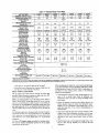
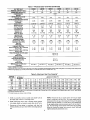
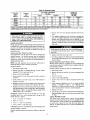
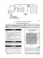
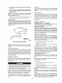
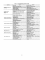
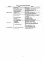
Table 13--Troubleshooting
SYMPTOM
He.ware failure.
(LED OFF)
Fan OWOFF
delay
(LED 1 FLASH)
Limit
switch
2 flashes)
REMEDY
Check 5-amp fuse on IGC*, power to urdt. 24-v circuit breaker, and
transformer. Units without a 24_/circuit breaker have an internal
ovehoad in the 24-v transformer. If the overlOad tdps, al_w 10 minutes
for automatk_reset.
LosS of power to control module (]GC)*.
modified
High Jim[t switch opens duhog heat
exchanger
warm-up
panod before fan-on
delay expires.
Limit switch opens within three minutes
alter
(LED
Guide-LED Error Codes
CAUSE
blower_ff
delay
timing
in Heating
mode.
Check the operation ol the indoor lan motor. Ensure
that the supply-air temperature rise is in accordance with the range
on the unit nameplate.
fauhs,
High temperature
limit switch
Fteme sense fault.
(LED 3 flashes)
4 consecutive limit switch faults,
(LED 4 flashes)
The IGC*
Dreserlt,
flame
Ignition lockout.
(LED 5 flashes)
Unit unsuccessfully
15 minutes.
Induced-draft motor fautt.
(LED 6 flashes)
IGC does
inadequate
motor
sensed
is open.
thai should
nol be
not sense
ignition for
is operating,"
Rollout switch
Rollout control toulL
(LED S flashes)
Microprocessor
has sensed
software or hardware.
9 Ftashes
Redundant Safety Circuit
Software Maitunolion
Check ignitor and flame sensor electrode spamng, gaps, etc. Ensure
that flame sense and ignition wires are propedy terminated. Verify
that unit is obtaining proper amount of gas.
Check for proper voltage. II motor is operating, check the speed
sensor plug/IGC Terminal J2 connection. Proper connection:
PIN 1-- White
PIN 2 -- Red
PIN 3 -- BlacK.
that induced°draft
Roltout switch fault.
(LED 7 flashes)
Reset unit. If problem persisls, replace control board.
Check operation ol indoor fan motor and that supply-air
temperature rise agrees with range on unit nameplate information.
airflow to unit
attempted
Ensure unit is fired on rate; ensure temperature rise is correct.
Ensure unit's external static pressure is within application guidelines.
Rot[out switch wiJl automatically reset, but IGC° will conchue to lOCkout unil. Check gas valve operation. Ensure that ioduce_-draft
blower wheel is properly secured to motor shaft. Reset unit at unit
disconnect.
has opened.
an eKor
in the
fl error code is not cleared by resetting unit power, replace the IGC'.
Irdemal processor fault that Wi, reset itself in t hour.
Fault can be caused by stray RF signals in the structure or nearby.
ThLs is a UL Requirement.
• WARNING_,_ : If the tGC must be replaced, be sure to ground yourse, to dissipate any electrical charge that may be present before handling new control board. The
IGC is sensitive to static electdcity and may be damaged it the necessary precautions are not taken.
IMPORTANT: Refer to Table 12--TrOubleshooting Guide-Heating
for additional troubleshOOtinganalysis.
LEGEND
_rdegrated
Gas Unit Controller
LED -- LightoEmitting Diode
32