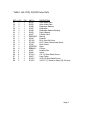
1
Catalog No.
X017
X014
X015
X016
Quantity
Description
Detail No.
2
Diaphragms
2
2
8
2
2
8
1
Diaphragms
Valves
“O” Rings
Diaphragms
Valves
“O” Rings
Mounted Bearing
38
50
48
38
50
48
42, 43
38
2
2
8
1
Diaphragms
Valves
“O” Rings
Mounted Bearing
38
50
48
42, 43
1
Motor
47
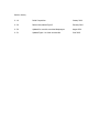
Part No.
A2187
A2187
B1408
BUNA010
A2187
B1408
BUNA010
DDRI-6632, and
A1294
A2187
B1408
BUNA010
DDRI-6632, and
A1294
PQ Motor
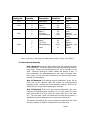
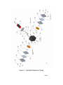
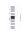
Note: In working on the pump unit, detail numbers refer to Figure 1 and Table 1.
3.1 Motor/Bearing Assembly
Step 1-Required Remove two sheet metal screws (88) securing the motor
to the pump body. The motor assembly may now be pulled away from the
pump body. Inspect the eccentric/bearing (42, 43) for looseness on the
shaft. Inspect the bearing for smooth rotation and absence of play. If
these components are undamaged/unworn, then wipe the bearing clean
with a fresh, lint free cloth and re-lubricate all over with any light grease.
Set aside for reassembling.
Step 2-If Required If the bearing requires replacement, loosen the set
screw (44) on the eccentric shaft and remove the bearing/eccentric
assembly (42,43). Replace with a new assembly, pushing it firmly on the
shaft as far as it will go, before tightening the set screw.
Step 2-If Required If the motor also requires replacement, then, after
removing the bearing/eccentric assembly (42, 43) also remove the three
motor plate screws (45) which secure the motor plate (46) to the motor
(47). The new motor, which is furnished with the cable and connector, is
assembled to the plate utilizing the three screws just removed (45).
The eccentric and bearing (42, 43) are replaced as described in step 2 and
the motor assembly is ready for re-attachment to the pump body.
Page 2