1
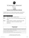
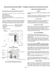
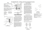
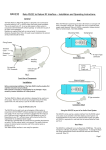
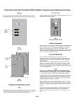
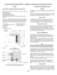
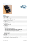
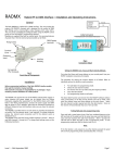
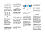
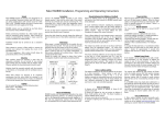
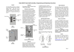
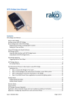
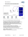
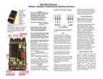
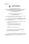
WAVMI User Manual
What is WAVMI
WAVMI allows mains voltage signals to be detected by a Rako wired system. So, the Rako system can
be made aware that certain circuits are active. This includes inputs from Alarm sensors & PIR
modules, central heating controls, fan motors – almost anything.
Figure 1
Send Commands to
Rako Wired system
AUX AC supply
eg. Electric Motor unit
Up to
5 circuits
eg. Mains switching PIR
unit
Issue A Jan 2012
Page 1 of 7
Getting started with WAVMI
Connect WAVMI to system
WAVMI must be connected to A RAKO Wired System. The simplest method is by connecting the RJ11
patch lead from the WAVMI to one of the RJ11 sockets on a system RAK-Link or RAK-Star. The RJ11
patch lead may also be plugged into a WA-Con access point.
If the WAVMI cannot be mounted near to a RAK-Link etc then the connection may be made by CAT5
cable to a Punch Down Daughterboard. The normal rules apply for terminations when connecting
the CAT5 cable in this way, as on a Wired Wallplate.
A WIRED INSTALLATION
INCLUDING WAVMI MODULES.
230v ac
RJ45 RAK4 cables
Internal
Figure 2
Lighting Circuits
Cat5 data cable
RAKLink
Wallplate1
WAVMI 1
Wallplate 2
WAVMI 2
WAVMI 3
In Figure 2 above:
WAVMI 1 is connected using Punch Down Daughterboard. It is at the end of the CAT5 cable so the
Term Jumper is set on its daughterboard.
WAVMI 2 is connected using Punch Down Daughterboard. It is in middle of the CAT5 cable so No
jumpers are set on its daughterboard.
WAVMI 3 is connected directly to a RAK-Link using RJ11 Patch Lead. A Daughterboard is not used
and No jumpers should be set on that daughterboard.
Issue A Jan 2012
Page 2 of 7
Connector for Punchdown
daughterboard
Figure 3
Pushbutton Setup Switch
RJ11 socket for direct connection
to a RAK-Link, RAK-Star or WP-Con
DC Power indicator
Inputs Indicator LED’s
Inputs Grouping Jumpers
Inputs terminal blocks
Aux AC Input
AC Wiring to the WAVMI
WAVMI has 5 inputs. Each input is a 4 way terminal block.
An input will register as ON when it has LIVE volts on it’s SL terminal.
The WAVMI must have a common Neutral connection between itself and the switching source.
Other aux Live, Neutral, Earth terminals are provided to allow tidy wiring to security PIR’s and so on.
Figure 4 shows some wiring examples.
230V AC SUPPLY
L
N
AC Switching PIR
sensor.
N
L
N
L
E
Central Heating
Motor
↓
(Eg Busch-Wachter 90 type 8653)
Figure 4a
Issue A Jan 2012
(Switched)
Ac Supply
to motor Figure 4b
Page 3 of 7
Example 1 (Figure 4a).
AC supply goes to WAVMI AC INPUT terminal block. Now
each 4 way terminal block has L,N,E supply. Live, Neutral is
fed to the PIR sensor. Switched Live Output of the PIR
sensor is fed back from the sensor to the WAVMI.
(L)
N
(E)
N
L
E
Central Heating
Motor
(Switched)
Ac Supply
to motor Figure 4c
Example 2 (Figure 4b).
Motor has switched ac supply (L & N) from heating
controller (not shown). Neutral connection is taken from
motor “N” terminal to WAVMI “N”. The (Switched) Live
terminal of the motor is connected to an “SL” input of the
WAVMI. The WAVMI does not require it’s own ac supply.
Example 3 (Figure 4c).
Motor has switched ac supply (L & N) from heating
controller (not shown). WAVMI has it’s own connection to
AC Neutral. Only the (Switched) Live from the motor to the
WAVMI “SL” is required to compete the circuit. WAVMI “L”
and “E” connections are optional.
Connecting WAVMI to RAKO System.
WAVMI AC Wiring MUST be kept separate from the Rako CAT5 and RJ11 system wiring
The WAVMI electronics takes its power from the RAKO wireless network. No other power supply is
required. Connect WAVMI by CAT5, or RJ11 to the wired system and power up.
The “Power” LED next to the RJ11 indicates that correct volts are being received from the system.
The Inputs Indicator LEDs (A,B,C,D,E) will illuminate at all times. A DIM LED indicates that it’s
corresponding Input is OFF. A BRIGHT LED indicates that it’s input is ON (LIVE)
Configure the WAVMI using RASOFT
For WAVMI to operate correctly with a RAKO system some initial setup must be performed. This is
done using a PC running RASOFT software and communicating with the Wired System via a RAKO
Bridge Product (WRE-Bridge, WA-Bridge of WTC-Bridge).
Open the Project File for the installed Rako system. Make sure that Rasoft is talking to the system
through a Bridge – Do not try to use RAUSB, RAH-Smart, RAV232 to make the connection. (Refer to
the Bridge User Instructions or the Wired System Programming Guide for assistance).
Press and Hold the WAVMI Setup Switch. After a few seconds the WAVMI will enter Setup Mode
and LED’s A,B,C,D,E on the WAVMI will start to blink.
Issue A Jan 2012
Page 4 of 7
A Message will pop up in Rasoft to acknowledge
that the WAVMI is in Setup Mode.
Press the Yes button to continue.
Add the WAVMI to the system. Give the
WAVMI a room number and name. Then press
Add button followed by Quit
The room number itself is not too important. Much more
important is that the WAVMI has its own unique identity.
It must not exist with the same Device Number as a
different device (WallPlate, RakLink etc) that is in the
same logical room. The Advanced Options check box will
allow manual setting of Device Number if this is proving
to be a problem
Wired Volt Free Setup screen will be shown:
Press Update List Button to make the new WAVMI appear on list at bottom LH Corner. (The Default
WAVMI can be deleted from the list).
The new WAVMI should now appear as On-line. If it does
not, try Updating the List again, or even closing &
reopening this setup screen (Under Controls-WiredWAVMI tab)
Issue A Jan 2012
Page 5 of 7
Program the WAVMI functions
The WAVMI is programmed in a similar way to a Rako Wired Wallplate.
Input Enable Buttons
The current Map
being Edited
The edit screen includes Input Enable buttons. Press in the buttons that correspond to WAVMI
inputs that have inputs connected. Leave the buttons for any unused inputs unpressed. Compare the
Input Enable buttons on this screen with figure 3. In each case only inputs A,B,C are in use.
(WAVMI uses the same RASOFT Programming screen as WAVFR. Since WAVMI only has 5 inputs, the
Inputs F,G,H,I,J must always be disabled).
Each Map has a Source and Action.
In this example the Source is that Input A is Made (Logic Low) for any time greater than zero
seconds. Each of the Source Buttons has a check box. This is used to set which inputs are used to
determine when this particular Map get triggered.
The Action for this map is that a Room 6, Scene 1 command is sent.
Other Maps will have different (or the same) source and will send appropriate commands.
Issue A Jan 2012
Page 6 of 7
Grouping Inputs
It is possible to program the WAVMI so it responds to multiple inputs, by creating a “Source” that
has multiple selections. The logic of multiple inputs can become confusing when considering all the
combinations of the multiple inputs.
Alternatively it is possible to use the “Inputs Grouping Jumpers” on the WAVMI circuit board.
In this example input A and input C have been
linked. This means that the programming of the
WAVMI for input A with respond if input A, OR
input C is active.
The jumpers should be used when there are (eg)
multiple PIR detectors covering a large area. If any
one of the PIR’s is triggered then the area lighting
can be switched ON.
Since A & C have been linked, the WAVMI software cannot distinguish between an A input and a C
input. Thus it is only necessary to program one of the inputs – ie just create a map for input A, not
input C also.
In this example inputs A & B are linked (group 1)
and inputs C & D are linked (group 2).
________________________________________________________________________________
Technical Support
For more information contact Rako Controls Ltd 01634 226666 www.rakocontrols.com
Issue A Jan 2012
Page 7 of 7