1
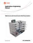
Applications
Engineering Manual
Chilled-Water VAV Systems
September 2009
SYS-APM008-EN
Chilled-Water
VAV Systems
John Murphy, applications engineer
Beth Bakkum, information designer
Preface
As a leading HVAC manufacturer, we deem it our responsibility to serve the
building industry by regularly disseminating information that promotes the
effective application of building comfort systems. For that reason, we
regularly publish educational materials, such as this one, to share
information gathered from laboratory research, testing programs, and
practical experience.
This publication focuses on chilled-water, variable-air-volume (VAV) systems.
These systems are used to provide comfort in a wide range of building types
and climates. To encourage proper design and application of a chilled-water
VAV system, this guide discusses the advantages and drawbacks of the
system, reviews the various components that make up the system, proposes
solutions to common design challenges, explores several system variations,
and discusses system-level control.
We encourage engineering professionals who design building comfort
systems to become familiar with the contents of this manual and to use it as
a reference. Architects, building owners, equipment operators, and
technicians may also find this publication of interest because it addresses
system layout and control.
Trane, in proposing these system design and application concepts, assumes no
responsibility for the performance or desirability of any resulting system design. Design of
the HVAC system is the prerogative and responsibility of the engineering professional.
“Trane” and the Trane logo are registered trademarks, and TRACE, System Analyzer and
TAP are trademarks of Trane, a business of Ingersoll-Rand.
© 2009 Trane. All rights reserved
Chilled-Water VAV Systems
SYS-APM008-EN
Contents
Preface ................................................................................................. ii
Overview of a Chilled-Water VAV System ........................... 1
Basic System Operation ................................................................... 3
Benefits of Chilled-Water VAV Systems ........................................... 6
Drawbacks/Challenges of Chilled-Water VAV Systems .................... 9
Common Building Types That Use Chilled-Water VAV Systems ..... 10
Primary System Components .................................................. 11
VAV Air-Handling Unit ...................................................................... 11
Indoor versus outdoor air-handling units ...................................... 12
Chilled-water cooling coil ............................................................. 15
Maximum face velocity to prevent moisture carryover ........ 17
Freeze prevention ................................................................. 18
Evaporative cooling ............................................................ 21
Heat source inside the VAV air-handling unit ............................... 23
Heating coil (electric, hot water, or steam) .......................... 23
Gas-fired burner ................................................................... 24
Recovered heat ................................................................... 26
Fans (supply, return, relief) .......................................................... 26
Supply fan only .................................................................... 26
Supply fan and relief fan ...................................................... 29
Supply fan and return fan .................................................... 30
Should the system use a relief fan or a return fan? ............. 30
Fan types ............................................................................. 32
Blow-thru versus draw-thru? ................................................ 35
Supply fan capacity modulation ........................................... 38
Air cleaning .................................................................................. 40
Particulate filters .................................................................. 40
Gaseous air cleaners ........................................................... 46
Biologicals ........................................................................... 48
Water management ..................................................................... 50
Casing performance (leakage and thermal) ................................. 51
VAV Terminal Units ......................................................................... 54
Types of VAV terminal units ......................................................... 55
Cooling-only VAV terminal units ........................................... 55
VAV reheat terminal units .................................................... 56
Fan-powered VAV terminal units ......................................... 58
Dual-duct VAV terminal units ............................................... 62
Minimum primary airflow settings ............................................... 62
Perimeter versus interior zones ................................................... 63
Typical combinations used in chilled-water VAV systems ............ 66
SYS-APM008-EN
Chilled-Water VAV Systems
iii
Air Distribution ............................................................................... 70
Supply duct system ..................................................................... 70
Supply-air diffusers .......................................................................74
Return-air path ............................................................................. 77
Chilled-Water System ..................................................................... 79
Types of water chillers ................................................................. 79
Chilled-water and condenser-water distribution ........................... 81
Design temperatures and flow rates ................................... 81
Control valve selection ........................................................ 83
Variable- versus constant-flow pumping .............................. 86
Freeze prevention ................................................................ 87
Condenser heat recovery ............................................................ 88
Waterside economizer .................................................................. 91
Thermal storage ........................................................................... 92
Hot-Water System .......................................................................... 92
Types of hot-water boilers ........................................................... 92
Hot-water distribution .................................................................. 94
Design temperatures and flow rates ................................... 94
Control valve selection ........................................................ 95
Variable- versus constant-flow pumping .............................. 97
Controls .......................................................................................... 98
System Design Issues and Challenges ............................... 99
Thermal Zoning ............................................................................... 99
Optimizing the number of zones ................................................. 99
Locating the zone sensor ........................................................... 100
Using wireless technology ..........................................................101
Ventilation ...................................................................................... 101
Zone-level ventilation requirements.............................................101
Minimum ventilation rate required in breathing zone (Vbz) ... 102
Impact of zone air-distribution effectiveness ...................... 102
System-level ventilation requirement .........................................104
Challenge of ventilating a multiple-zone VAV system ......... 104
Calculating system intake airflow (Vot) ................................ 105
Appendix A, “calculated Ev” method ................................. 109
Heating versus cooling design ............................................ 111
Systems with multiple recirculation paths .......................... 113
Fixed outdoor-air damper position ...................................... 113
Proportional outdoor-air damper control ............................. 114
Direct measurement and control of outdoor airflow .......... 115
Dedicated outdoor-air systems ................................................... 115
Dynamic reset of intake airflow .................................................. 117
Humidity Control ........................................................................... 118
Dehumidification .........................................................................118
Full-load versus part-load dehumidification performance ... 118
Impact of minimum airflow settings for VAV terminal units 119
Resetting supply-air temperature ....................................... 120
Reheating supply air at the VAV terminal units ................... 120
iv
Chilled-Water VAV Systems
SYS-APM008-EN
Methods for improving dehumidification performance ...... 121
After-hours dehumidification ............................................... 125
Humidification............................................................................ 126
Energy Efficiency ........................................................................... 127
Minimum efficiency requirements ............................................. 127
Minimum equipment efficiencies ....................................... 127
Maximum allowable fan system power .............................. 128
Simultaneous heating and cooling limitation ...................... 130
VAV fan control ................................................................... 132
Demand-controlled ventilation ............................................ 132
Opportunities to further reduce system energy use ................. 132
Acoustics ....................................................................................... 135
Defining an acoustical model .................................................... 135
Specific acoustical recommendations ....................................... 138
Air-cooled chillers ................................................................ 139
Water-cooled chillers ........................................................... 140
VAV air-handling units ......................................................... 141
VAV terminal units .............................................................. 145
System Design Variations ....................................................... 147
Cold-Air VAV Systems ...................................................................
Benefits of cold-air distribution ..................................................
Challenges of cold-air distribution..............................................
Effects of delivering cold air into the zone ...........................
Impact on overall system energy consumption ..................
Avoiding condensation on components ...............................
Best practices when using cold-air distribution .........................
Single-Zone VAV ............................................................................
Best practices in a single-zone VAV application .........................
Air-to-Air Energy Recovery ............................................................
Benefits of outdoor-air preconditioning.....................................
Drawbacks of outdoor-air preconditioning .................................
Best practices for preconditioning outdoor air...........................
Dual-Duct VAV Systems ................................................................
Dual- versus single-fan system ..................................................
Variable- versus constant-volume to the zone ...........................
Best practices for dual-duct VAV systems .................................
147
147
149
149
151
153
155
157
158
160
161
162
162
165
166
167
169
System Controls .......................................................................... 171
Unit-Level Controls ........................................................................ 171
VAV air-handling unit ...................................................................171
Discharge-air temperature control ...................................... 171
Ventilation control ............................................................... 171
Supply-fan capacity control ................................................. 172
Airside economizer control ................................................. 174
Building pressure control .................................................... 178
Return-fan capacity control ................................................. 181
Safeties ............................................................................... 182
SYS-APM008-EN
Chilled-Water VAV Systems
v
VAV terminal units ..................................................................... 183
Zone temperature control ................................................... 183
Ventilation control ............................................................... 184
Space pressure control ....................................................... 187
Safeties ............................................................................... 188
Water chiller ............................................................................... 188
Condensing pressure control ............................................. 188
Hot-water boiler ......................................................................... 190
Return water temperature control ...................................... 190
System-Level Control .................................................................... 190
Coordination during different operating modes ......................... 191
Occupied mode .................................................................. 191
Occupied standby mode .................................................... 192
Unoccupied mode .............................................................. 193
Morning warm-up (or cool-down) mode ............................. 194
Scheduling ................................................................................. 196
Chilled-water plant ..................................................................... 197
Hot-water plant .......................................................................... 197
System optimization .................................................................. 198
Optimal start ....................................................................... 198
Optimal stop ....................................................................... 199
Unoccupied “economizing” ................................................ 199
Fan-pressure optimization ................................................. 200
Supply-air-temperature reset ............................................. 202
Ventilation optimization ...................................................... 205
Pump-pressure optimization .............................................. 208
Chilled-water temperature reset ........................................ 208
Hot-water temperature reset ............................................. 209
Condenser-water temperature (chiller-tower) optimization . 210
Coordination with other building systems .................................. 211
Glossary .......................................................................................... 213
References .................................................................................... 225
Index ............................................................................................... 230
vi
Chilled-Water VAV Systems
SYS-APM008-EN
Overview of a
Chilled-Water VAV System
A typical chilled-water variable-air-volume (VAV) system consists of a VAV airhandling unit that serves several individually controlled zones. Each zone has
a VAV terminal unit that varies the quantity of air delivered to maintain the
desired temperature in that zone.
The primary components of a typical chilled-water VAV system (Figure 1)
include:
•
VAV air-handling unit that contains a mixing box; filters; a chilled-water
cooling coil; possibly a heating coil, gas-fired burner, or electric heater; a
variable-volume supply fan; possibly a return or relief fan; and controls
•
VAV terminal unit with a temperature sensor for each independently
controlled zone
•
Supply ductwork and supply-air diffusers
•
Return-air grilles, ceiling plenum, and return ductwork
•
Water chiller(s) with associated water distribution pumps and heat
rejection equipment (cooling towers for water-cooled chillers, condenser
fans for air-cooled chillers)
•
Hot-water boiler(s), with associated water distribution pumps, or electric
heat
•
System-level controls
Figure 1. Primary components of a chilled-water VAV system
VAV
air-handling
unit
supply ductwork
supply-air diffuser
VAV terminal unit
chilled-water
distribution
pumps
water chillers
SYS-APM008-EN
Chilled-Water VAV Systems
1
Overview of a Chilled-Water VAV System
The VAV air-handling unit can be located either outdoors, typically on the roof
of the building, or indoors, typically in a penthouse or mechanical equipment
room in the basement or on one of the occupied floors of the building. A
building may use a single air-handling unit or several units, depending on its
size, load characteristics, and function. Return air from inside the building is
drawn back to the air-handling unit. Some of this air is exhausted while the
rest enters the air-handling unit through a return-air damper to be mixed with
outdoor air that enters through a separate damper. This mixed air typically
passes through a filter, a heating coil, a chilled-water cooling coil, and a
supply fan before it is discharged from the unit (Figure 2).
Figure 2. Typical air-handling unit used in a VAV system
discharge
plenum
filter
return-air
damper
supply
fan
chilled-water
cooling coil
hot-water
heating coil
outdoor-air
damper
The supply air is distributed through ductwork that is typically located in the
ceiling plenum above each floor (Figure 1). The supply ductwork delivers air
to each of the VAV terminal units, then this air is introduced into the zones
through supply-air diffusers. Each independently controlled zone has a VAV
terminal unit that varies the quantity of air delivered to maintain the desired
temperature in that zone. Air typically returns from the zones through ceilingmounted return-air grilles and travels through the open ceiling plenum to a
central return duct that directs this return air back to the air-handling unit.
The chilled water for cooling is provided by a chilled-water system, which
includes one or more water chillers with associated water distribution pumps
and heat rejection equipment (cooling towers for water-cooled chillers,
condenser fans for air-cooled chillers).
Heating can be accomplished in several ways. One approach uses a heating
coil (hot water, steam, or electric) or gas-fired burner inside the air-handling
unit. In this configuration, the air-handling unit can warm the supply air
during cold weather or during a morning warm-up period. A second
approach uses individual heating coils (hot water or electric) installed in the
VAV terminal units. Each coil is controlled to warm the supply air when
necessary. A third approach uses perimeter baseboard radiant heat within
those zones that require heat. The baseboard heaters can be controlled
separately or by the controller on the VAV terminal unit.
2
Chilled-Water VAV Systems
SYS-APM008-EN
Overview of a Chilled-Water VAV System
When hot water is used for heating, it is provided by a hot-water system,
which includes one or more boilers with associated water distribution
pumps.
Each VAV terminal unit is equipped with a unit controller that regulates the
flow of primary (supply) air to the zone to provide cooling, heating, and
ventilation for the zone it serves. The VAV air-handling unit is also equipped
with its own controller. A system-level controller ties the individual VAV
terminal unit controllers to the controller on the air-handling unit, providing
intelligent, coordinated control so that the individual pieces of equipment
operate together as a system.
Basic System Operation
Unlike a constant-volume system, which delivers a constant quantity of air at
varying temperatures, a VAV system delivers a varying quantity of constanttemperature air. The following section describes, in a very simple manner,
how a typical chilled-water VAV system operates. For a more detailed
discussion, see “System Controls,” p. 171.
Zone is occupied and requires cooling
A sensor in each zone compares the dry-bulb temperature in the zone to a
setpoint, and the VAV terminal responds by modulating the volume of supply
air to match the changing cooling load in the zone. As the cooling load
decreases, the VAV terminal responds by reducing the quantity of cold air
delivered to the zone.
The VAV air-handling unit is controlled to maintain a constant supply-air
temperature. Depending on the condition of the outdoor air, this may involve
modulating a control valve on the chilled-water cooling coil, using outdoor
air for “free cooling” (airside economizing), or modulating a control valve on
the hot-water heating coil or gas-fired burner. The central supply fan
modulates to maintain the pressure in the supply ductwork at a setpoint; this
pressure ensures that all zones receive their required quantities of cold air.
The outdoor air damper allows the required amount of fresh, outdoor air to
be brought into the system for ventilation.
Zone is occupied, but requires no cooling or heating
As the cooling load in the zone decreases, the damper in the VAV terminal
closes until it reaches the minimum airflow setting. As the load continues to
decrease further, the constant quantity of cool air causes the dry-bulb
temperature in the zone to drop below the cooling setpoint. If the
temperature in the zone falls below the cooling setpoint, but remains above
the heating setpoint, the VAV terminal takes no control action, remaining at
its minimum airflow setting. The temperature range between the cooling and
heating setpoints is called the deadband (Figure 3).
SYS-APM008-EN
Chilled-Water VAV Systems
3
Overview of a Chilled-Water VAV System
zone dry-bulb temperature
Figure 3. Occupied zone temperature setpoints
occupied cooling setpoint
deadband
occupied heating setpoint
The air-handling unit is controlled to maintain a constant supply-air
temperature by either modulating the chilled-water control valve, using the
airside economizer, or modulating the heating control valve. The supply fan
modulates to maintain a constant pressure in the supply ductwork, and the
outdoor-air damper brings in at least the minimum required amount of
outdoor air for ventilation.
Zone is occupied and requires heating
In many chilled-water VAV systems, zones that require heating include a
heating coil (hot water or electric) in the VAV terminal unit. Alternatively,
some systems use baseboard radiant heat located along the perimeter walls
within the zone.
When the temperature in the zone drops below the heating setpoint, the
controller on the VAV terminal unit activates the heating coil, warming the air
supplied to the zone. If baseboard radiant heat is used instead, it is activated
to add heat directly to the zone.
The air-handling unit is controlled to maintain a constant supply-air
temperature, by either modulating the chilled-water control valve, using the
airside economizer, or modulating the heating control valve. The supply fan
modulates to maintain a constant pressure in the supply ductwork, and the
outdoor-air damper brings in at least the minimum required amount of
outdoor air.
Zone is unoccupied
When the zone is scheduled to be unoccupied, most buildings relax the zone
setpoints, allowing the temperature in the zone to either increase or
decrease. (In fact, this practice is required in many buildings by local codes or
4
Chilled-Water VAV Systems
SYS-APM008-EN
Overview of a Chilled-Water VAV System
energy standards.) These new setpoints are often called setback
temperatures, and the result is a much wider deadband (Figure 4).
Figure 4. Unoccupied zone setback temperatures
zone dry-bulb temperature
unoccupied cooling setback temperature
occupied cooling setpoint
deadband
occupied heating setpoint
unoccupied heating setback temperature
During unoccupied periods, as long as the temperature in the zone is within
this wider deadband, the VAV terminal unit closes to prevent any air from
being supplied to the zone. Also, any local heat (heating coil in the VAV
terminal or baseboard heat within the zone) is off.
If all zones served by the air-handling unit are unoccupied and the zone
temperatures are within the deadband, the supply fan typically shuts off.
Because the building is unoccupied, no ventilation is required and the
outdoor-air damper is closed.
Some systems incorporate a “timed override” button on the zone
temperature sensor, which allows the occupant to temporarily switch the
system into the occupied mode, even though it is scheduled to be
unoccupied. After a fixed period of time (three hours, for example), the
system automatically returns the zone to the unoccupied mode.
In addition, an occupancy sensor can be used to indicate that a zone is
actually unoccupied, even though it is scheduled to be occupied. This
“unoccupied” signal can be used to switch the zone to an “occupied
standby” mode, in which all or some of the lights can be shut off, the
temperature setpoints can be raised or lowered slightly, the ventilation
delivered to that zone can be reduced, and the minimum airflow setting of
the VAV terminal can be lowered. When the occupancy sensor indicates that
the zone is again occupied, the zone is switched back to the normal occupied
mode.
SYS-APM008-EN
Chilled-Water VAV Systems
5
Overview of a Chilled-Water VAV System
Benefits of Chilled-Water VAV Systems
A comprehensive list of system benefits depends on which type of system is
the basis of comparison. The following section discusses some of the
primary benefits of using a chilled-water VAV system.
Provides multiple zones of comfort control
Chilled-water VAV systems are popular because they are capable of
controlling the temperature in many zones with dissimilar cooling and
heating requirements, while using a central air-handling unit. This is
accomplished by providing a VAV terminal unit and temperature sensor for
each independently controlled zone.
When the sun is shining against the west side of the building in the late
afternoon, a VAV system can provide an increased amount of cool supply air
to keep the perimeter zones along the west exposure comfortable, while
throttling back the airflow to the zones along the east exposure so as not to
overcool them.
Load diversity results in less supply airflow and a smaller
supply fan
For more information on the impact of
load diversity in multiple-zone systems,
refer to the Trane Air Conditioning Clinic
titled “Cooling and Heating Load
Estimation” (TRG-TRC002-EN).
6
When an air-handling unit is used to deliver air to multiple zones, the method
used to size that supply fan depends on whether the system is designed to
deliver a constant or variable quantity of air to each zone. If the system is
designed to deliver a constant quantity of air to each zone (a constant-volume
system), the supply fan must be sized by summing the peak (design) airflow
requirements for each of the zones it serves, regardless of when those peak
requirements occur. However, if the system varies the quantity of air
delivered to each zone, as is the case in a VAV system, the supply fan can be
sized based on the one-time, worst-case overall (“block”) airflow requirement
of all the zones it serves, since all zones do not require peak (design) airflow
simultaneously.
Chilled-Water VAV Systems
SYS-APM008-EN
Overview of a Chilled-Water VAV System
Impact of load diversity on sizing the supply fan
As seen in the example shown in Table 1,
the peak space cooling loads do not
necessarily occur at the same time for all
spaces served by the system. Room 101
has several west-facing windows, so the
peak (highest) space sensible cooling load
occurs in late afternoon (4:00 p.m.) when
the sun is shining directly through the
windows. Room 102 has several eastfacing windows, so the peak space
sensible cooling load occurs in the morning
(8:00 a.m.) when the rising sun shines
directly through its windows.
If a single, constant-volume system is
used to serve these two zones, the system
must deliver 3,440 cfm (1.62 m3/s) to
Room 101 and 2,880 cfm (1.36 m3/s) to
Room 102 at all times. So, a constantvolume supply fan needs to be sized to
deliver 6,320 cfm (2.98 m3/s). This is
often called the “sum-of-peaks” airflow.
Although Rooms 101 and 102 peak at
different times during the day, there will
be a single instance in time when the sum
of these two space loads is highest. If
these two rooms are served by a single
VAV system, the supply fan need only be
sized for the time when the sum of the
space sensible cooling loads is the highest,
which occurs at 4:00 p.m. in this example.
So, a variable-volume supply fan need
only be sized to deliver 5,990 cfm (2.82
m3/s). This is often called the “block”
airflow.
This zone-by-zone load variation
throughout the day (called “load
diversity”) is the reason that VAV systems
can deliver less air (18 percent less in this
example) and use smaller supply fans,
than multiple-zone constant-volume
systems.
Similarly, the peak cooling coil loads do
not necessarily occur at the same time for
all VAV air-handling units served by a
central chilled-water plant. This systemby-system load variation (“block load”) is
the reason that the chilled-water plant
serving VAV air-handling units can be
sized for less total capacity than if the
building is served by multiple rooftop VAV
systems.
Table 1. Sum-of-peaks versus block airflow
8:00 a.m.
4:00 p.m.
space sensible supply airflow, space sensible supply airflow,
cooling load,
cfm (m3/s)
cooling load,
cfm (m3/s)
Btu/hr (W)
Btu/hr (W)
Room 101
(faces West)
44,300
(13,000)
2,040
(0.96)
74,600
(21,900)
3,440
(1.62)
Room 102
(faces East)
62,400
(18,300)
2,880
(1.36)
55,300
(16,200)
2,550
(1.20)
“Block” airflow
“Sum-of-peaks”
airflow
4,920
(2.32)
5,990
(2.82)
3,440 + 2,880 = 6,320 cfm
(1.62 + 1.36 = 2.98 m3/s)
Opportunity to save energy
The part-load energy savings inherent with a VAV system is twofold. First,
reducing the amount of air delivered at part load creates an opportunity to
reduce the fan energy required to move this air. The magnitude of this energy
savings depends on the method used to modulate the capacity of the fan.
Second, the reduced airflow across the cooling coil allows the chilled-water
control valve to reduce water flow in order to deliver a constant supply-air
temperature. This results in a reduction in cooling energy compared to a
constant-volume reheat system.
SYS-APM008-EN
Chilled-Water VAV Systems
7
Overview of a Chilled-Water VAV System
In addition, using chilled water as the cooling medium presents further
opportunity for energy savings through the use of centralized, higherefficiency cooling equipment and a water distribution system.
Flexibility of equipment location
Chilled-water VAV systems offer significant flexibility when locating the
various components of the system. The design team can maximize the
amount of usable floor space in the building by using an air-cooled chiller,
outdoor air-handling units, and VAV terminal units installed in the ceiling
plenum. Or, equipment can be located indoors (water-cooled chillers and
indoor air-handling units) to improve access for maintenance and prolong
equipment life.
Centralizing the cooling and heating equipment minimizes disruption of the
occupants when maintenance or repair is required. Similarly, the VAV
terminals can be installed above corridors to minimize disruption of the
occupants.
Typically, the only equipment located within the occupied space is the
temperature sensor mounted on the wall. However, as mentioned earlier, in
cold climates some VAV systems may use baseboard radiant heat located
along the perimeter walls within the occupied space.
This flexibility also makes chilled-water VAV systems a popular choice for
taller buildings, which are not well-suited for roof-mounted DX equipment
and large areas for vertical air shafts.
Finally, using water chillers for cooling centralizes the refrigerant inside a few
pieces of equipment. This minimizes the risks associated with refrigerant
leaks compared to having refrigerant-containing equipment spread
throughout the facility.
Flexibility of air-handling equipment
In general, air-handling units offer greater flexibility than packaged DX
equipment. Air-handling units can typically be applied to a wider range of
operating conditions, making them better suited for systems requiring
variable airflow, lower cfm/ton (L/s/kW) (such as those with high percentages
of outdoor air or colder supply-air temperatures), and tighter space control
requirements.
In addition, air-handling units are typically available with a broader range of
options, such as energy recovery devices, dehumidification enhancements,
fan choices, air cleaning equipment, sound attenuation choices, and casing
performance (thermal and leakage) options.
Able to adapt to changes in building use
Most chilled-water VAV systems use an open return-air plenum to allow air
from all the zones to return back to the VAV air-handling unit. This, combined
with the use of flexible ductwork to connect the VAV terminal units to supply8
Chilled-Water VAV Systems
SYS-APM008-EN
Overview of a Chilled-Water VAV System
air diffusers, provides flexibility for the system to adapt to potential changes
in building use.
Also, using chilled water as the cooling medium offers more flexibility to
adapt to future changes in the building load. It is easier to design a chilledwater air-handling unit with “reserve capacity” than it is for a directexpansion (DX) refrigeration system. In addition, centralized chilled-water
and hot-water plants can also be designed to have “reserve capacity,” which
can be used by any of the air-handling units they serve.
Drawbacks/Challenges of Chilled-Water
VAV Systems
Similar to the discussion of benefits, a list of drawbacks is dependent on
which type of system is the basis of comparison. The following section,
however, discusses some of the primary challenges related to chilled-water
VAV systems, along with some potential ways to address those challenges.
More sophisticated system to design, control, and
operate
The flexibility of a chilled-water VAV system, achieved through the use of
more sophisticated equipment and controls, also means that it can be more
challenging to design, control, and operate properly, than a system that uses
more “packaged” components.
Single-zone, packaged DX equipment is simpler to design, install, and
operate. But the packaged nature of this equipment limits flexibility,
minimizes the potential to reduce energy use, and can increase maintenance
since the equipment is distributed throughout the facility.
The challenge for the design team is to take advantage of the benefit of
flexibility, while keeping the system easy to operate and maintain. Preengineered controls and easy-to-use building automation systems are two
technologies that can help achieve this balance.
Ceiling space and vertical shafts are required to deliver
conditioned air
Because the conditioned air is delivered by a central supply fan, ceiling space
is required to duct the air from the air-handling unit to the VAV terminals, and
eventually to the occupied spaces. In addition, for a multi-story building, one
or more vertical air shafts may be needed to duct the outdoor air to floor-byfloor air-handling units. These vertical shafts take up some usable floor space
in the building.
To minimize impact on the floor plan, these shafts are often located in the
core of the building, next to elevator shafts and restrooms.
SYS-APM008-EN
Chilled-Water VAV Systems
9
Overview of a Chilled-Water VAV System
More sophisticated equipment to maintain and repair
Water chillers and hot-water boilers are more complicated pieces of
equipment than packaged DX units. Some facilities prefer to use smaller,
simpler equipment that can be maintained by the facility staff.
Many buildings that use chilled-water VAV systems use facility staff to
perform regular maintenance (such as changing filters, inspecting and
tightening fan belts, and cleaning drain pans) and then hire an outside
service provider for repair work and regular maintenance of the larger pieces
of equipment.
The right answer for each project depends on the expertise and availability of
the facilities maintenance staff.
Common Building Types That Use
Chilled-Water VAV Systems
Chilled-water VAV systems are used in almost all building types, but the most
common uses include:
10
•
Commercial office buildings
•
Schools (both K-12 and higher education)
•
Hospitals, clinics, and medical office buildings
•
Large hotels and conference centers
•
Large retail centers (shopping malls)
•
Airports
•
Laboratories
•
Industrial facilities and manufacturing processes
Chilled-Water VAV Systems
SYS-APM008-EN
Primary System Components
This chapter discusses the primary components of a typical chilled-water VAV
system in greater detail. For details on specific pieces of equipment, consult
the manufacturer.
VAV Air-Handling Unit
Return air from inside the building is drawn into the VAV air-handling unit
(AHU) (Figure 5) through the return-air damper and is mixed with outdoor air
that enters through the outdoor-air damper. This mixed air passes through a
filter, a heating coil, a chilled-water cooling coil, the supply fan, and possibly
a final filter before it is discharged into the supply ductwork.
Figure 5. Typical air-handling unit used for VAV applications
discharge
plenum
filter
return-air
damper
supply
fan
chilled-water
cooling coil
hot-water
heating coil
outdoor-air
damper
A few large air-handling units or
several smaller units?
A building may use a few large airhandling units or several smaller units,
depending on size, load characteristics,
and function. A study commissioned by
the U.S. General Services Administration
(GSA) concluded that using multiple
small air-handling units is more
desirable than using fewer large airhandling units (Callan, Bolin, and
Molinini 2004).
Smaller air-handling units allow more
diversity for after-hours operation,
provide more flexibility, result in less
cross-contamination between zones,
allow for greater optimization of
setpoints for energy savings, and often
avoid the need for return fans. A survey
of five newly constructed buildings
revealed that using smaller air-handling
units (< 50,000 cfm [24 m3/s]) resulted
in 7 to 8 percent energy savings
compared to using larger air-handling
units.
SYS-APM008-EN
VAV air-handling units are typically available with a broad range of options,
such as energy recovery devices, dehumidification enhancements, fan
choices, air cleaning equipment, sound attenuation choices, and casing
performance (thermal and leakage) options. Because of this flexibility, there
is generally no “standard” configuration for a VAV system.
When multiple units are used, a common approach is to dedicate one airhandling unit (and, therefore, one VAV air distribution system) to serve each
floor of the building. An advantage of this approach is that it minimizes the
number and/or size of vertical shafts used to route ductwork inside the
building. Using fewer and/or smaller vertical air shafts will likely increase the
amount of usable floor space in the building. Another advantage is that, if the
floors are leased to different organizations, it offers a simple way to bill
tenants individually for their HVAC energy use.
An alternative approach is to use one air-handling unit to serve each
exposure of the building. For example, all the west-facing zones are served
by one unit, all the east-facing zones are served by another unit, and so on.
The advantage of this approach is that all the zones served by an air-handling
Chilled-Water VAV Systems
11
Primary System Components
unit are thermally similar, potentially allowing for reduced energy use. A
drawback is that, depending on the shape of the building, it may necessitate
the use of multiple, vertical air shafts, which can result in less usable floor
space. This approach may be combined with the use of floor-by-floor airhandling units to serve the interior zones.
Indoor versus outdoor air-handling units
The VAV air-handling unit can be located either outdoors or indoors. An
outdoor unit is typically installed on the roof of the building. An indoor unit is
typically installed in a penthouse, the basement, or a mechanical equipment
room located on one of the occupied floors of the building.
Table 2 describes the advantages and drawbacks of each location.
Table 2. Indoor versus outdoor location of air-handling units
Indoor AHU
Advantages:
Disadvantages:
• Preventive maintenance on the AHU is performed indoors, away
from harsh weather.
• Requires indoor floor space that could have otherwise been used by
the building owner or leased to a tenant.
• Thermal performance of the AHU casing is less critical since indoor • May require the equipment room to be conditioned to prevent
temperatures are milder, resulting in less heat loss/gain.
condensation (sweating) on the exterior surfaces of the AHU.
Outdoor AHU
Advantages:
Disadvantages:
• Frees indoor floor space that can be used by the building owner or
leased to a tenant.
• Preventive maintenance on the AHU may need to be performed
during harsh weather or require the construction of an outdoor
service corridor.
• Less concern about condensation (sweating) on the exterior
surfaces of the AHU, since any condensation drains onto the roof
surface.
• May require more space for vertical air shafts, reducing the amount
of usable floor space.
• Roof structure may need to be strengthened to support the added
weight of the AHUs.
• Thermal performance of the AHU casing is more critical since
extreme outdoor temperatures result in more heat loss/gain.
Installing the air-handling units indoors requires floor space that could have
otherwise been used by the building owner or leased to a tenant. Following
are several strategies used to minimize the floor space required by an indoor
air-handling unit:
•
Stacked configurations
If the frame of the air-handling equipment is sturdy enough, components
can be stacked on top of one another to minimize the footprint, or floor
space required.
The top unit in Figure 6 depicts an example VAV air-handling unit, with
both a supply fan and relief fan, configured on one level. The overall
length is 23.2 ft (7.1 m) and the width is 7.8 ft (2.4 m).
12
Chilled-Water VAV Systems
SYS-APM008-EN
Primary System Components
Figure 6. Example of a stacked configuration to reduce unit length
OA
RA
SA
EA
EA
RA
SA
OA
Source: Images from Trane TOPSS program
The bottom unit in Figure 6 depicts the same components configured in a
stacked arrangement, where the diverting box and relief fan are stacked
on top of the other modules. This reduces the overall length to 13.8 ft
(4.2 m). The width of the unit remains the same but, of course, the unit is
taller—10.2 ft (3.2 m) compared to 5.1 ft (1.6 m) for the non-stacked unit.
In many buildings with slab-to-slab heights of 12 ft (3.7 m) or more, the
added height of a stacked air-handling unit is not an issue. And, by using a
stacked configuration, the footprint of this example unit is reduced by 40
percent.
Of course, the larger the airflow capacity, the taller the air-handling unit
will be. So, for very large units, stacking may not be possible due to the
floor-to-floor height limitation of the building.
•
Multiple fans (dual fans or fan arrays)
Using multiple fans, rather than a single supply fan, can also result in a
shorter air-handling unit (Figure 27, p. 35). For a given airflow, a unit with
multiple fans uses several, smaller-diameter fan wheels, rather than a
single, larger-diameter fan wheel. Upstream and downstream spacing
(length) requirements are typically a function of the fan wheel diameter—
except for very small sizes where access requirements dictate the
necessary spacing. Therefore, using multiple, smaller-diameter fan
wheels can shorten the upstream and downstream spacing required, and
can shorten the length of the overall air-handling unit (see “Fan types,”
p. 32). However, using multiple fans is typically less efficient and
increases the cost of the air-handling unit.
•
Dual-path configuration
Another way to reduce AHU footprint is to use a dual-path configuration
to separately condition the recirculated return air (RA) and outdoor air
(OA). Each air path includes a dedicated cooling coil, but the same fan
serves both paths (Figure 7).
For more information on direct-drive
fans and using multiple versus single
fans, refer to the Trane engineering
bulletin titled “Direct-Drive Plenum Fans
for Trane Climate Changer™ Air
Handlers” (CLCH-PRB021-EN).
SYS-APM008-EN
Chilled-Water VAV Systems
13
Primary System Components
Figure 7. Dual-path VAV air-handling unit
Avoiding fan surge in a dual-path
AHU
When a dual-path configuration is used
for a VAV air-handling unit, preventing
the supply fan from operating in the
surge region can be more challenging.
As supply airflow is reduced at part load,
outdoor airflow through the OA path may
remain nearly constant (to ensure
proper ventilation) while the recirculated
airflow through the RA path is reduced.
Therefore, the pressure drop through
the OA path remains high while the
pressure drop through the RA path
decreases. This high-pressure drop
through the OA path can cause the
supply fan to surge at reduced supply
airflow.
To help prevent the fan from operating in
the surge region:
•
Size the components in the OA path
for a low airside pressure drop. This
may involve increasing the casing
size for the top section (OA path) of
the air-handling unit.
•
Carefully select the supply fan to
reduce the potential for surge. A
direct-drive plenum fan (p. 35) often
provides the greatest flexibility for
selection.
•
Implement the fan-pressure
optimization control strategy
(p. 199), which allows the fan to
generate less pressure at part load.
•
14
Implement the ventilation
optimization control strategy
(p. 204), which reduces outdoor-air
intake flow during partial occupancy.
With less intake airflow, the pressure
drop through the OA path decreases.
OA
SA
RA
Source: Image adapted from Trane TOPSS program
The face area of a cooling coil is dictated by the design airflow through
that coil, and the size of the coil typically dictates the footprint of the airhandling unit: the larger the coil, the larger the AHU must be to house it.
In a dual-path unit, because the RA cooling coil only conditions the
recirculated air, rather than the mixture of outdoor and recirculated air, it
can be smaller than it would be for a single-path unit.
Consider an example VAV air-handling unit that is sized for 13,000 cfm
(6.1 m3/s) of supply air, of which 3,500 cfm (1.6 m3/s) is outdoor air and
9,500 cfm (4.5 m3/s) is recirculated return air. In a single-path
configuration, the single cooling coil must be sized for the total 13,000
cfm (6.1 m3/s). For this unit, a size 30 AHU casing results in a coil face
velocity of 435 fpm (2.2 m/s).
Note: The unit “size” typically represents the nominal face area of the
cooling coil, in terms of ft2. In this example, the face area of the size 30 airhandling unit is 29.90 ft2 (2.78 m2).
In a dual-path configuration, the RA (lower) cooling coil need only be
sized for the 9,500 cfm (4.5 m3/s) of recirculated air. For this path, a size 21
AHU casing results in a coil face velocity of 456 fpm (2.3 m/s). The OA
(upper) coil, which is sized for the 3,500 cfm (1.6 m3/s) of outdoor air,
requires a size 8 AHU casing, which results in a coil face velocity of 438
fpm (2.2 m/s). The overall footprint of the dual-path unit (size 8 casing
stacked on top of a size 21 casing) is smaller than that of a dual-path unit
(size 30 casing), although the dual-path unit is taller (Figure 8 and
Table 3).
Chilled-Water VAV Systems
SYS-APM008-EN
Primary System Components
Figure 8. Example footprint reduction from using a dual-path air-handling unit
(see Table 3)
6.7 ft
(2.0 m)
Dual-path AHU
-Size 21 on bottom
-Size 8 on top
7.8 ft
(2.4 m)
11.4 ft (3.5 m)
Single-path AHU (Size 30)
11.7 ft (3.6 m)
Table 3. Impact of dual-path configuration on AHU footprint and weight
Size 30
Dual-path AHU
bottom: Size 21
top: Size 8
11.7 x 7.8
(3.6 x 2.4)
11.4 x 6.7
(3.5 x 2.0)
Single-path AHU
AHU footprint, ft (m)
AHU height, ft (m)
AHU weight, lbs (kg)
•
5.1 (1.6)
7.5 (2.3 m)
2800 (1270)
2800 (1270)
Cold-air distribution
By reducing the supply-air temperature, less supply airflow is required to
offset the sensible cooling loads in the zones. Reducing supply airflow
can allow for the selection of smaller air-handling units, which can
increase usable (or rentable) floor space.
Cold-air VAV systems typically deliver supply air at a temperature of 45°F
to 52°F (7°C to 11°C). For more information, see “Cold-Air VAV Systems,”
p. 147.
Chilled-water cooling coil
Figure 9. Actual cooling coil
Cooling in a chilled-water VAV system is accomplished using a chilled-water
coil in the VAV air-handling unit. Cooling coils are finned-tube heat
exchangers consisting of rows of tubes that pass through sheets of formed
fins (Figure 9). As air passes through the coil and contacts the cold tube and
fin surfaces, heat transfers from the air to the water flowing through the
tubes (Figure 10).
SYS-APM008-EN
Chilled-Water VAV Systems
15
Primary System Components
Figure 10. Chilled-water cooling coil
airflow in
airflow out
water in
water out
In most applications, the cooling coil also dehumidifies as water vapor in the
air condenses on the cold fin surfaces of the coil. This water then drains
down the coil surfaces, drops into the drain pan located beneath the cooling
coil, and is piped away by the condensate drain line.
The coil tubes are usually constructed of copper, and the coil fins of
aluminum. For some applications, coils may use copper fins or a
manufacturer may cover the coil surfaces with a coating to minimize
corrosion.
Selection of the cooling coil impacts the cost of installing, operating, and
maintaining both the VAV air-handling unit and the chilled-water system. For
example, the amount of material used to construct the coil—overall size,
number of tubes, number of fins—determines the initial cost: more material
increases the cost. But the size of the cooling coil also dictates the weight and
footprint of the air-handling unit: the larger the coil, the larger the AHU must
be to house it. A larger AHU may require a larger mechanical room (reducing
usable or rentable floor space), limit access for service, impact the amount of
structural support needed, or challenge the arrangement of ductwork and
piping.
Because the cooling coil is also part of the air distribution system, its
geometry—size, number of rows, fin spacing, and fin profile—contributes to
the airside pressure drop and affects the energy used and sound generated
by the fans. A larger AHU will typically result in a lower airside pressure drop
through its components, which can reduce fan energy (see example in
Table 4).
Finally, because a chilled-water cooling coil is also part of the chilled-water
system, its geometry contributes to the waterside pressure drop and affects
the energy used by the pumps. And, the extent to which coils raise the
chilled-water temperature dramatically affects both the installed cost of
chilled-water piping and pumping energy. Coil performance can even
influence the efficiency of the water chiller. For further discussion, see
“Chilled-Water System,” p. 79.
16
Chilled-Water VAV Systems
SYS-APM008-EN
Primary System Components
Maximum face velocity to prevent moisture carryover
If a cooling coil also dehumidifies, it must be selected to prevent moisture
carryover at design air velocities. While a long-time industry rule-of-thumb
has been to select cooling coils for a face velocity no greater than 500 fpm
(2.5 m/s) at design airflow, many of today’s heat exchanger surfaces have
been engineered to prevent moisture carryover at much higher velocities.
The footprint of the AHU cabinet is typically dictated by the size of the cooling
coil, and the size of the cooling coil is often dictated by the allowable face
velocity. An overly restrictive limit on coil face velocity results in the selection
of a larger air-handling unit than may be necessary. This increases the cost of
the equipment, results in heavier equipment that requires more structural
support, and requires more floor space. Table 4 shows an example selection
of a 13,000-cfm (6.1-m3/s) VAV air-handling unit, selected to provide 525 MBh
(154 kW) of total cooling capacity. Arbitrarily limiting coil face velocity to 500
fpm (2.5 m/s) results in the need to select a size 30 unit.
Note: The unit “size” typically represents the nominal face area of the cooling
coil, in terms of ft2. In the example depicted in Table 4, the face area of the
size 30 air-handling unit is 29.90 ft2 (2.78 m2).
A size 25 unit, with its reduced coil face area, would result in a coil face
velocity of 521 fpm (2.6 m/s) at design airflow. While this is higher than the
industry rule-of-thumb, it is well below the manufacturer’s tested limit for
preventing moisture carryover.
Table 4. Impact of cooling coil face velocity on AHU footprint and weight
Coil face area, ft2 (m2)
Face velocity, fpm (m/s)
Coil rows
Size 25 AHU
Size 30 AHU
Size 35 AHU
24.97 (2.32)
29.90 (2.78)
34.14 (3.17)
521 (2.6)
435 (2.2)
381 (1.90)
6 rows
6 rows
4 rows
Fin spacing, fins/ft (fins/m)
103 (338)
83 (272)
137 (449)
Total cooling capacity, MBh
(kW)
525 (154)
525 (154)
525 (154)
Airside pressure drop, in
H2O (Pa)
0.69 (173)
0.50 (125)
0.36 (90)
Fluid pressure drop, ft H2O
(kPa)
12.1 (36.3)
13.6 (40.6)
9.1 (27.1)
12.1 x 6.7
(3.7 x 2.0)
12.1 x 7.8
(3.7 x 2.4)
13.5 x 8.0
(4.1 x 2.4)
9.1 (2.8)
9.1 (2.8)
9.3 (2.8)
3350 (1520)
3570 (1620)
4700 (2130)
AHU footprint1, ft (m)
AHU height1, ft (m)
AHU weight1, lbs (kg)
1 Based on a typical VAV air-handling unit layout consisting of an OA/RA mixing box, high-efficiency filters,
hot-water heating coil, chilled-water cooling coil, airfoil centrifugal supply fan, and a top-mounted
discharge plenum.
Selecting the smaller (size 25) air-handling unit results in lower cost of the
equipment, reduces the weight of the unit by 6 percent, and reduces the
footprint (floor space required) by 14 percent (Figure 11).
SYS-APM008-EN
Chilled-Water VAV Systems
17
Primary System Components
Figure 11. Impact of coil face velocity on AHU footprint (see Table 4)
Size 25
Size 35
Size 30
Note that in order to deliver equivalent capacity, the cooling coil in the
smaller-sized AHU requires more fins than the coil in the larger-sized AHU.
This slightly increases the cost of the coil and, along with the smaller coil face
area, increases the airside-pressure drop—0.69 in H2O (173 Pa) for size 25
unit versus 0.50 in H2O (125 Pa) for the size 30 unit. This does impact fan
energy use. However, in a VAV air-handling unit, the airside-pressure drop
decreases quickly as supply airflow is reduced at part load, so the actual
impact on annual fan energy use is lessened. Finally, the smaller coil reduces
the fluid pressure drop—12.1 ft H2O (36.3 kPa) for size 25 unit versus 13.6 ft
H2O (40.6 kPa) for the size 30 unit—which may decrease pumping energy.
If the goal for a project is to minimize footprint and/or equipment cost,
consider specifying that the face velocity at design airflow should not exceed
90 percent (for example) of the manufacturer’s tested and published limit to
prevent moisture carryover, rather than specifying an arbitrary maximum coil
face velocity of 500 fpm (2.5 m/s). For example, if the manufacturer’s
published limit is 600 fpm (3.0 m/s), specify that the coil face velocity not
exceed 540 fpm (2.7 m/s) at design airflow.
However, if the goal for a project is to reduce energy use, consider selecting a
slightly larger air-handling unit. The example in Table 4 also shows a
selection for a size 35 unit. With more surface area, the cooling coil can
deliver equivalent capacity with only four rows of tubes, rather than six.
Fewer rows, along with the larger coil face area, decreases the airsidepressure drop to 0.36 in H2O (90 Pa) and decreases the fluid pressure drop to
9.1 ft H2O (27.1 kPa). The result is reduced fan and pumping energy. However,
this does increase the cost, footprint (Figure 11), and weight of the airhandling unit.
Freeze prevention
As discussed in “Ventilation,” p. 101, at part-load conditions a properly
controlled VAV air-handling unit typically brings in a high percentage of
outdoor air. During cold weather it is difficult to mix the outdoor air and
recirculated return air when the two air streams are at widely differing
18
Chilled-Water VAV Systems
SYS-APM008-EN
Primary System Components
temperatures. Incomplete mixing results in distinct temperature layers
(stratification) in the resulting “mixed” air stream (Figure 12). If a layer of
sub-freezing air moves through an unprotected chilled-water or hot-water
coil, the water can freeze and damage the coil.
Figure 12. Temperature stratification during cold weather
80°F
(27°C)
return air
warm air
10°F
(-12°C)
outdoor air
mixed air
cold air
cooling coil
Typically, a low-limit thermostat (or “freezestat”) is installed on the upstream
face of the water coil. This sensor measures the lowest temperature in any
12-in. (30-cm) section of the coil face. If the temperature of the air entering
any section of the coil approaches 32°F (0°C), the unit controller responds by
stopping the supply fan, closing the outdoor-air damper, or both. This
adversely affects occupant comfort and indoor air quality.
If a chilled-water coil is likely to be exposed to air that is colder than 32°F
(0°C), the system must include some method to protect the coil from freezing.
Several common freeze-prevention methods are listed below. Choose the
method that best suits the application.
•
Drain the chilled-water cooling coils during cold weather.
This requires vent and drain connections on every coil, as well as shutoff
valves to isolate the coils from the rest of the chilled-water distribution
system. After draining each coil, use compressed air to remove as much
water as possible, add a small amount of antifreeze to prevent any
remaining water from freezing, and disconnect the freezestat to avoid
nuisance trips.
The advantage of this approach is that it has minimal impact on the cost
of the air-handling unit and has no impact on energy use. However, it
does increase maintenance cost, especially in locations where the
temperature can fluctuate widely during seasonal transitions, requiring
the coils to be drained and filled several times each season.
•
SYS-APM008-EN
Add antifreeze to the chilled-water system.
Adding antifreeze (such as glycol) to the chilled-water system lowers the
temperature at which the solution will freeze. Given a sufficient
concentration of glycol, no damage to the system will occur. For a VAV
system, since the cooling coil is typically not used during sub-freezing
Chilled-Water VAV Systems
19
Primary System Components
weather, a concentration that provides “burst protection” is usually
sufficient for the chilled-water system (Table 13, p. 87). A concentration
that provides “freeze protection” is only needed in those cases where no
ice crystals can be permitted to form (such as a coil loop that operates
during very cold weather) or where there is inadequate expansion volume
available. Make sure to also use an inhibitor package to help resist
corrosion.
The advantage of this approach is that it is predictable and relatively easy
to maintain. However, antifreeze degrades the heat-transfer performance
of cooling coils and chillers, often increasing the size and cost of these
components. In addition, it increases the fluid pressure drop through the
coils and chillers, impacting pumping energy use.
•
Preheat the outdoor air before it mixes with the recirculated air.
Using an electric heater, steam coil, or hot-water heating coil to preheat
the sub-freezing outdoor air before it enters the mixing box decreases the
temperature difference between the two air streams, which improves
mixing effectiveness and reduces stratification.
The advantage of this approach is that it is predictable and effective. In
cold climates, a source of heat may already be needed in the centralized
VAV air-handling unit. However, because the heat source needs to be
located in the outdoor air stream, this approach may limit flexibility or
increase the cost of the air-handling unit. And, if a hot-water or steam
preheat coil is used, they also require some method of freeze prevention
(see “Heating coil,” p. 23).
One common approach is to use a preheat coil with integral face-andbypass dampers. These dampers modulate to vary the amount of heat
transferred to the air, while allowing full water or steam to flow through
the coil tubes.
•
Use air-to-air energy recovery to preheat the outdoor air.
As an alternative to the prior method, an air-to-air energy recovery device
(such as a coil loop, fixed-plate heat exchanger, heat pipe, or wheel) can
be used to preheat the entering outdoor air during cold weather (see “Airto-Air Energy Recovery,” p. 160).
The advantage of this approach is that it also reduces cooling and heating
energy use, and can allow for downsizing of cooling and heating
equipment. However, such a device does increase the cost of the airhandling unit and adds a pressure drop to both the outdoor and exhaust
air streams, which increases fan energy use.
Figure 13. Air-mixing baffles
•
Use air-mixing baffles.
This configuration of baffles (Figure 13), located immediately
downstream of the mixing box, adds rotational energy and increases the
velocity of the air stream, which improves mixing (blending) to prevent or
minimize temperature stratification.
The advantage of this approach is that it works consistently and requires
no maintenance. However, it does increase the cost and length of the airhandling unit, since distance is needed downstream for the air to finish
mixing and slow down before reaching the filters. Also, the baffles add
20
Chilled-Water VAV Systems
SYS-APM008-EN
Primary System Components
pressure drop (typically 0.2 in. H2O [50 Pa]), which increases fan energy
use, and mixing effectiveness decreases as airflow is reduced.
•
Introduce cold outdoor air downstream of the cooling coil.
This configuration, sometimes called a “winterizer,” uses a combination
of two different-sized air-handling units (Figure 14) configured to allow
the outdoor air to be introduced downstream of the cooling coil whenever
the outdoor air is colder than 32°F (0°C). The smaller air-handling unit,
sized for the minimum required ventilation airflow, contains filters and
possibly a small preheat coil.
Figure 14. “Winterizer” configuration
preheat coil
OA
winter
OA
summer
SA
RA
cooling coil
Source: Image adapted from Trane TOPSS program
This “winterizer” configuration removes the length and pressure drop
associated with a preheat coil from the main air path, resulting in a
shorter air-handling unit than if a conventional preheat coil, air-mixing
baffles, or an energy-recovery device is used. And, since it adds no static
pressure drop to the design of the supply fan, it has less impact on fan
energy than these other approaches. However, the cost of the second,
smaller air-handling unit is typically higher than an air-mixing baffles, and
it requires a second, smaller set of filters that need to be replaced
periodically.
Evaporative cooling
Using an evaporative process to cool the air can reduce the energy used by
mechanical cooling equipment. However, it requires careful attention to
water treatment, periodic cleaning, and routine maintenance to ensure safe
and efficient operation. Finally, it consumes water, which may be in limited
supply in the arid climates where evaporative cooling provides the greatest
energy-saving benefit.
Direct evaporative cooling introduces water directly into the air stream,
usually with a spray or wetted media. The water evaporates as it absorbs
heat from the passing air stream, which lowers the dry-bulb temperature of
the air. Evaporation of the water, however, also raises the dew point of the air
(Figure 15).
SYS-APM008-EN
Chilled-Water VAV Systems
21
Primary System Components
Figure 15. Direct versus indirect evaporative cooling
65°F DB
58°F WB
OA’ 53°F DP
dire
ct e
vap
ora
SA supplemental
tive
coo
mechanical
ling
cooling
OA’
SA
55°F DB
22°F DP
For more information on evaporative
cooling, refer to Chapter 40, “Evaporative
Air-Cooling Equipment,” in the 2008
ASHRAE Handbook - HVAC Systems and
Equipment (www.ashrae.org).
93°F DB
58°F WB
OA 22°F DP
indirect evaporative cooling
The leaving-air temperature depends on how much the dry-bulb temperature
of the entering air exceeds its wet-bulb temperature. For example, if the
condition of the entering outdoor air (OA) is 93°F dry bulb and 58°F wet bulb
(34°C DB, 14°C WB), and the direct evaporative process is 80 percent
effective, the condition of the leaving air (OA’) will be 65°F DB and 58°F WB
(18°C DB, 14°C WB).
DBTleaving = DBTentering – effectiveness x (DBTentering – WBTentering)
DBTleaving = 93°F – 0.80 x (93°F – 58°F) = 65°F
(DBTleaving = 34°C – 0.80 x [34°C – 14°C] = 18°C)
In a VAV system that is designed to supply air at 55°F (13°C) dry bulb, a
conventional cooling coil is usually required to supplement the evaporative
cooling process, and further cool the supply air to the desired setpoint
(Figure 15). The system could be designed for warmer supply-air temperature
and/or use an aggressive supply-air-temperature reset strategy to minimize
the need for supplemental mechanical cooling, but these approaches also
increase supply airflow and fan energy use.
Any cooling energy saved is offset somewhat by the increased fan energy
use, as the evaporative media increases the airside pressure drop that the
supply fan must overcome.
Indirect evaporative cooling typically uses an evaporative cooling tower to
cool water, and then pumps this water through a conventional cooling coil to
cool the air. This approach does not involve the evaporation of water into the
air stream, so it does not increase the dew point of the air (Figure 15). The
evaporation process occurs outside the building in the cooling tower.
In some applications, indirect evaporative cooling is implemented using a
stand–alone cooling tower (or similar device) and a separate coil located
upstream of the conventional cooling coil. However, in a chilled-water VAV
system, because a water distribution system is already part of the system, a
more common approach is to add a plate-and-frame heat exchanger to the
chilled-water system, allowing cool condenser water (from the cooling tower)
22
Chilled-Water VAV Systems
SYS-APM008-EN
Primary System Components
to cool the chilled water (see Figure 78, p. 91). This configuration is often
called a waterside economizer.
Heat source inside the VAV air-handling unit
Heating in a VAV system can be accomplished in several ways. While many
systems include heating coils (hot water or electric) in the VAV terminal units
or baseboard radiant heat installed within the zone, some systems also
include a heating coil (hot water, steam, or electric) or gas-fired burner inside
the air-handling unit. This centralized source of heat is primarily used to: 1)
warm up the building in the morning prior to occupancy and 2) maintain the
desired supply-air temperature during extremely cold weather, preventing air
that is too cold from being delivered to the zones that may still require
cooling (such as interior zones).
Heating coil (electric, hot water, or steam)
An electric heater, installed inside the air-handling unit at the factory,
simplifies jobsite installation and avoids the need to install a boiler and hotwater (or steam) distribution system in the building or to provide gas service
to the unit.
A hot-water or steam heating coil can also be mounted inside the AHU in the
factory, but requires a boiler and hot-water (or steam) distribution system to
be installed in the building. This approach centralizes the heating equipment
and can incorporate various methods of heat recovery to reduce energy use
(see “Condenser heat recovery,” p. 88).
A hot-water coil that contains pure water (no antifreeze) should not be used if
the coil will be exposed to air that is colder than 32°F (0°C). During normal
operation, with both the circulation pump and boiler operating, the water
inside the coil may not freeze until it is exposed to air that is much colder than
32°F (0°C). But if the pump fails, the stagnant water inside the tubes of the
coil will be at risk of freezing, and the consequences of a frozen coil (burst
tubes and water leaks) are too severe. If a hot-water coil is likely to be
exposed to air that is colder than 32°F (0°C), consider one of the following
methods of freeze protection:
SYS-APM008-EN
•
Add antifreeze to the hot-water system.
Adding antifreeze (such as glycol) to the hot-water system lowers the
temperature at which the solution will freeze. Given a sufficient
concentration of glycol, no damage to the system will occur. For a VAV
system, since the hot-water coil operates during sub-freezing weather, a
concentration that provides “freeze protection”—to prevent the solution
from forming crystals at the coldest expected outdoor temperature—is
required (Table 13, p. 87). Make sure to also use an inhibitor package to
help resist corrosion. At the warmer fluid temperatures used in the hotwater system, the impact of glycol on pressure drop is much lower than in
cooling coils.
•
Use air-to-air energy recovery to preheat the outdoor air.
An air-to-air energy recovery device (such as a coil loop, heat pipe, fixedplate heat exchanger, or wheel) can typically preheat the entering outdoor
Chilled-Water VAV Systems
23
Primary System Components
air to a temperature warmer than 32°F (0°C), minimizing (or possibly
avoiding) the risk of coil freezing (see “Air-to-Air Energy Recovery,”
p. 160).
The advantage of this approach is that it also reduces cooling and heating
energy use, and can allow for downsizing of cooling and heating
equipment. However, such a device does increase the cost of the airhandling unit and adds a pressure drop to both the outdoor and exhaust
air streams, which increases fan energy use.
Steam heating coils can also freeze if the condensate is allowed to remain
inside the tubes of the coil. If a steam coil is likely to be exposed to air that is
colder than 32°F (0°C):
•
Use a distributing-type steam coil. This type of coil has steam
“distributing” tubes inside the larger “condensing” tubes. Orifices
located in the bottom of the distributing tubes are directed toward the
condensate return header, improving condensate drainage.
•
If possible, pitch the steam coil toward the condensate connection to
assist with drainage. Also, make sure the air-handling unit is installed
within the manufacturer’s tolerance for levelness.
•
Properly size, install, and maintain the steam trap.
•
Because steam coils are very sensitive to piping practices, it is extremely
important to follow the manufacturer’s instructions regarding installation
of the condensate piping, steam trap, and vacuum breakers.
Gas-fired burner
Figure 16. Direct-fired versus indirectfired gas burners
Direct-fired gas burner
Alternatively, gas-fired burners can be installed inside the air-handling unit at
the factory. This simplifies installation at the jobsite and may eliminate the
need for a boiler and hot-water (or steam) distribution system in the building.
In addition, gas-fired burners do not require freeze protection and may cost
less to operate than an electric heater.
Direct-fired burners locate the flame directly in the air stream, while indirectfired burners separate the combustion process from the air stream through
the use of a heat exchanger (Figure 16).
Direct-fired burners are simpler (because no heat exchanger is needed) and
more efficient (because there are no heat transfer losses associated with the
heat exchanger) than indirect-fired burners. However, direct-fired burners
introduce the products of combustion into the air stream. This requires
careful control of the combustion process, but is generally considered safe in
most commercial and industrial applications. However, many building codes
and industry standards prevent the use of direct-fired burners for any parts of
a building that contain sleeping quarters.
•
Indirect-fired gas burner
24
Location within the air-handling unit
Indirect-fired burners should be located downstream of the supply fan
(Figure 17). In this location, the pressure inside the casing of the airhandling unit is greater than the pressure outside. This positive pressure
difference reduces the likelihood that combustion gases will be drawn
into the supply air stream and, therefore, into the occupied spaces.
Chilled-Water VAV Systems
SYS-APM008-EN
Primary System Components
Figure 17. Indirect-fired burner located downstream of supply fan
indirect-fired
gas burner
supply fan
OA
SA
RA
RA
Source: Image adapted from Trane TOPSS program
Direct-fired burners should be located upstream of the supply fan
(Figure 18). This helps avoid unstable burner operation and nuisance trips
of airflow safety switches, which are often caused by localized high
velocities when the burner is located in close proximity to the fan
discharge.
Figure 18. Direct-fired burner located upstream of supply fan
supply fan
direct-fired
gas burner
OA
SA
SA
RA
Source: Image adapted from Trane TOPSS program
•
Gas supply
The supply of natural gas connected to the gas train must be within the
range of allowable pressures. A higher inlet gas pressure may require a
pressure regulator, while a lower inlet pressure may require an oversized
gas train. Consult the manufacturer for specific gas pressure and volume
requirements.
•
Combustion gas flue stack (indirect-fired burner only)
For air-handling units located outdoors, the manufacturer often provides
a combustion gas flue stack to be installed at the jobsite. Because the
burner is located outside of the building, concerns about combustion
gases are lessened.
For units located indoors, the engineer must design the combustion gas
flue stack based on heat output, horizontal and vertical lengths of the
stack, type of material to be used, and all applicable codes. For long or
high-pressure-drop stacks, a flue booster fan may be required. And, a
SYS-APM008-EN
Chilled-Water VAV Systems
25
Primary System Components
barometric damper may be required if a tall chimney produces excessive
draft.
•
Controls
Because airflow across the gas-fired burner varies, the heating capacity of
the burner must be modulated to prevent the temperature rise through
the burner from exceeding the maximum allowable limit. For most VAV
applications, this likely requires a burner with a 10:1 turndown ratio. This
means the burner can operate at a capacity as low as 10 percent of its
rated capacity. In addition, air temperature sensors on the entering and
leaving sides of the burner are needed to protect it from damage.
Finally, allow the supply fan to continue to operate for a period of time
after the gas-fired burner has been shut off, allowing the heat exchanger
to dissipate any residual heat. Consult the manufacturer for the length of
this “cool-down” period.
In VAV applications, the air velocity across a direct-fired burner must
remain within a specific range for safe operation. In this case,
manufacturers typically provide an adjustable opening that automatically
varies the opening size as airflow changes, keeping the air velocity
relatively constant.
Recovered heat
In some applications, heat may be recovered from another part of the HVAC
system. Common sources of recoverable heat include:
•
Warm condenser water leaving a water-cooled chiller or hot refrigerant
vapor leaving the compressor in an air-cooled chiller (see “Condenser
heat recovery,” p. 88)
•
Another air stream, or another location in the same air stream, using an
air-to-air heat exchanger (see “Air-to-Air Energy Recovery,” p. 160)
Fans (supply, return, relief)
Fans are used to move air throughout the various components of a VAV
system. Depending on the application, the system may include: 1) a supply
fan only, 2) a supply fan and a relief (or exhaust) fan, or 3) a supply fan and a
return fan.
Supply fan only
In this configuration (Figure 19), the supply fan must create high enough
pressure at its outlet (A) to overcome the pressure losses associated with
pushing the air through the main supply ductwork, VAV terminal units,
supply-duct runouts, and supply-air diffusers. (Note: If the system uses series
fan-powered VAV terminals, the small terminal fan is used to overcome the
pressure losses between the terminal unit and the zone. For further
discussion, see “Fan-powered VAV terminal units,” p. 58.)
26
Chilled-Water VAV Systems
SYS-APM008-EN
Primary System Components
Figure 19. VAV system with supply fan only (100% recirculated air)
VAV
terminal
unit
static pressure relative to outdoors
zone
return-air grille,
ceiling plenum,
return ductwork
AHU
main supply
ductwork
supply duct
runouts,
diffusers
zone
A
+
supply
fan
0
-
C
B
In addition, the supply fan must create low enough pressure at its inlet (B) to
overcome the pressure losses associated with drawing the return air out of
the zones and through the return-air grilles, through the open ceiling plenum
and/or return ductwork, and then through the return-air damper, filter, and
coils inside the air-handling unit.
Figure 19 depicts a typical “supply fan only” system operating with 100
percent recirculated air, as it might operate during unoccupied periods or
morning warm-up (no outdoor air is being brought into the building). Due to
the pressure drop through the return-air path, the pressure at the inlet to the
air-handling unit (C) is lower than the ambient pressure. With this negative
pressure differential, no air will be forced out of the relief damper.
With this “supply fan only” configuration, the only way for any air to leave
the building (which is required if outdoor air is to be brought into the
building) is for the pressure in the zone and return-air path to increase.
SYS-APM008-EN
Chilled-Water VAV Systems
27
Primary System Components
Figure 20 depicts this same system operating with 25 percent outdoor air.
The pressure in the zone and return-air path has increased to the point that
the pressure at the inlet to the air-handling unit (C) is now higher than the
ambient pressure. This positive pressure differential will force air out through
the relief damper.
Figure 20. VAV system with supply fan only (25% outdoor air)
VAV
terminal
unit
static pressure relative to outdoors
zone
return-air grille,
ceiling plenum,
return ductwork
+
0
C
main supply
ductwork
AHU
A
supply duct
runouts,
diffusers
zone
supply
fan
D
-
B
return-air
damper
However, the pressure inside the mixing box (D) must still be lower than the
ambient pressure in order for air to be drawn in through the outdoor-air
damper. So the return-air damper must be closed far enough to create the
necessary pressure drop (from C to D). This requires the supply fan to
generate a larger pressure differential (inlet to outlet, from B to A) in order to
deliver the desired supply airflow and bring in the required amount of
outdoor air.
It also results in a higher pressure in the zone, which could cause doors to
stand open without latching. For proper control of building pressure, this
“supply fan only” configuration should usually be avoided and either a relief
fan or return fan should be used.
28
Chilled-Water VAV Systems
SYS-APM008-EN
Primary System Components
Supply fan and relief fan
As an alternative, a relief fan can be added to the system. In this
configuration (Figure 21), the supply fan must still create a high enough
pressure at its outlet (A) to overcome the pressure losses associated with the
supply-air path, and create a low enough pressure at its inlet (B) to overcome
the pressure losses associated with the return-air path and the components
inside the air-handling unit.
Figure 21. VAV system with supply and relief fans (25% outdoor air)
VAV
terminal
unit
static pressure relative to outdoors
zone
return-air grille,
ceiling plenum,
return ductwork
AHU
supply
ductwork
supply duct
runouts,
diffusers
zone
A
+
relief
fan
0
-
supply
fan
E
C
B
relief
damper
However, the relief fan is used to raise the pressure of the air to be exhausted
(from C to E) so that it is high enough to overcome the pressure loss
associated with the relief damper, and force the excess air out of the building.
Adding the relief fan allows the system to exhaust the air that is to be
replaced by fresh, outdoor air, and does so without increasing the pressure in
the zone or requiring the supply fan to generate a larger pressure differential.
In smaller VAV systems that do not use an airside economizer cycle, local
exhaust fans (serving restrooms or copy centers) and local barometric relief
dampers may exhaust enough air without the need for a central relief fan.
SYS-APM008-EN
Chilled-Water VAV Systems
29
Primary System Components
Supply fan and return fan
The final configuration uses a fan in the return-air path, rather than in the
exhaust air path. When the system includes a return fan, the supply fan must
still create the same pressure at its outlet (A) to overcome the pressure losses
associated with the supply-air path (Figure 22).
Figure 22. VAV system with supply and return fans (25% outdoor air)
VAV
terminal
unit
static pressure relative to outdoors
zone
return-air grille,
ceiling plenum,
return ductwork
AHU
main supply
ductwork
supply duct
runouts,
diffusers
zone
A
+
0
F
supply
fan
return
fan
-
C
B
return-air
damper
However, the pressure at the inlet of the supply fan (B) only needs to be low
enough to overcome the pressure losses associated with drawing the return
air through the return-air damper, filter, and coils (or the pressure associated
with drawing the outdoor air through the outdoor-air damper, whichever is
higher). The return fan is used to overcome the pressure losses associated
with drawing the return air out of the zones and through the return-air grilles,
open ceiling plenum and/or return ductwork. It must also generate enough
pressure (F) to push any relief air out through the relief damper.
Should the system use a relief fan or a return fan?
The “supply fan and relief fan” configuration usually works best in VAV
systems that use an open ceiling plenum for part of the return-air path
(Table 5). Systems with relief fans are easier to control, typically lower the
cost of the air-handling unit, and are often less costly to operate than systems
with return fans. (See “Building pressure control,” p. 178.)
When the pressure drop through the return-air path is very high (which may
be the case in a larger system with a fully ducted return-air path), evaluate
both the relief- and the return-fan configurations. If the supply fan is capable
of handling the pressure drop of both the supply- and return-air paths, then
the relief-fan configuration is preferred for the reasons mentioned above. Use
a return fan only if the return-air path adds more pressure drop than the
supply fan can handle.
30
Chilled-Water VAV Systems
SYS-APM008-EN
Primary System Components
Table 5. Return fan versus relief fan in a VAV system
Return Fan
Advantages:
Disadvantages:
• Lower differential pressure across the supply fan, if the
pressure drop of the return air path is greater than the
pressure drop of the outdoor air path (which is likely in most
VAV systems).
• Higher operating costs, especially in applications with extended hours of
economizer cooling1 (the return fan must run whenever the supply fan
operates).
•
• Potentially lower installed cost for a system with a fully
ducted, return-air path. A smaller differential pressure across
the supply fan can result in a smaller fan motor and variablespeed drive.
•
Potential for air to leak out through the relief damper, because the returnair plenum inside the air-handling unit operates at a positive pressure (F
in Figure 22). Note: Using low-leak relief dampers can minimize air
leakage to the outdoors.
More complex (expensive) fan-speed control. Controlling the pressure in
the return-air plenum inside the air-handling unit requires an additional
pressure sensor and modulating device (either a damper actuator or
variable-speed drive), and the pressure sensor is difficult to situate
because this plenum is usually small and turbulent. (See “Return-fan
capacity control,” p. 181.)
• Requires more fan power at part load. The pressure in the return-air
plenum inside the air-handling unit must always be high (positive) enough
to force air out through the relief damper. The return-air damper must
therefore create a significant pressure drop between the positive returnair plenum and the negative mixed-air plenum. This added pressure drop
requires more combined fan power than a system with a relief fan.
• Limited layout flexibility. The return fan must be situated between the airhandling unit and the closest leg of the return-air path (usually near the
air-handling unit) because it must draw the entire return path negative
relative to the occupied spaces. It must also discharge into the return-air
plenum during modulated economizer operation.
Relief fan
Advantages
Disadvantages
• Lower operating cost. In some applications, the relief fan can • Potential for negative building pressure at low loads. This condition can
occur when a variable-speed drive controls the relief fan, supply airflow is
remain off during “non-economizer” hours1 and operate at low
very low, and required relief airflow is less than is delivered with the relief
airflow during many “economizer” hours. Also, the return-air
fan operating at lowest speed. Note: Using a constant-speed relief fan
damper can be sized for a lower pressure drop.
with a modulating relief damper avoids this problem.
• Simpler control scheme. One less sensor and one less
actuator simplifies installation and air balancing. Applications • Potential for air to leak in through the relief damper because the return-air
plenum inside the air-handling unit operates at negative pressure
with a relatively low pressure drop through the return-air path
whenever the relief fan is turned off (C in Figure 21). Note: Using low-leak
(which is common in a system that uses an open ceiling
relief dampers can minimize air leakage from outdoors.
plenum for part of the return-air path) can use lower-cost fans
as well as fewer (less costly) controls.
• Higher differential pressure across the supply fan than in a system with a
return fan. The supply fan must overcome the pressure drop of the return
• Greater layout flexibility. The relief fan can be positioned
path as well as the supply path. For this reason, an air-handling unit with
anywhere in the return-air path because the supply fan draws
a relief fan may not be capable of delivering the pressure differential
the return path negative (relative to the occupied spaces)
required in a system with a fully ducted return-air path.
during modulated economizer operation. An air-handling unit
installed in the basement with a central relief fan installed on
the roof can take advantage of winter stack effect to lower
operating cost.
1 In many applications, when the system is bringing in minimum ventilation airflow (not in airside economizer mode), local exhaust fans (in restrooms and copy
centers, for example) and exfiltration (due to positive building pressurization) are often sufficient to relieve all the air brought into the building for ventilation. In
this case, no central relief is needed and the central relief fan can be turned off, only needing to operate during economizer mode.
SYS-APM008-EN
Chilled-Water VAV Systems
31
Primary System Components
Fan types
VAV air-handling units are typically available with several choices for fan
types and sizes. This affords the opportunity to select a fan that optimizes the
balance of energy efficiency, acoustics, and cost.
The most common type of fan used in VAV systems is a centrifugal fan, in
which air enters the center of the fan wheel (axially) and follows a radial path
through it. A centrifugal fan may be characterized by the shape of the fan
blades, whether it contains a fan scroll (housed) or not (plenum), whether it is
belt-driven or direct-drive, and whether one or multiple fan wheels are used.
•
For more information on fan types, refer
to the Trane Air Conditioning Clinic titled,
“Air Conditioning Fans” (TRG-TRC013-EN).
Shape of fan blades
A forward curved (FC) fan has blades that are curved in the direction of
wheel rotation. These fans are operated at relatively low speeds and are
used to deliver large volumes of air against relatively low static pressures.
Due to the inherently light construction of the fan wheel, FC fans are
typically used in smaller systems that require static pressures of 4 in. H2O
(1000 Pa) or less. FC fans are typically less costly, but usually less
efficient, than the other types.
Systems that require greater than 3 in. H2O (750 Pa) of static pressure are
usually best served by the more-efficient backward curved (BC), backward
inclined (BI), or airfoil-shaped (AF) fan blades. In larger systems, the
higher fan efficiencies can result in significant energy savings.
A BI fan has flat blades that are slanted away from the direction of wheel
rotation, while a BC fan has shaped blades that are curved away from the
direction of wheel rotation. Their rugged construction allows them to
operate at higher speeds than FC fans, and makes them suitable for
moving large volumes of air in higher static-pressure applications. Also,
BC and BI fans are typically more efficient than FC fans.
A refinement of the BI fan changes the shape of the blade from a flat plate
to that of an airfoil, similar to an airplane wing. The smooth airflow across
the blade surface reduces turbulence and noise within the wheel. The
result is that an AF fan typically requires less input power than other fan
types (Table 6).
Table 6. Impact of fan type on input power (brake horsepower)1
Fan type and size
Input power,
bhp (kW)
Rotational speed,
rpm
Housed FC, 22.375 in. (568 mm)
16.07 (11.98)
979
Housed AF, 25 in. (635 mm)
14.65 (10.92)
1433
Belt-drive plenum AF, 35.56 in. (903 mm)
16.15 (12.04)
1108
Direct-drive plenum AF, 30 in. (762 mm)
14.85 (11.07)
1388
1 Based on a typical VAV air-handling unit configuration (OA/RA mixing box, high-efficiency filter, hot-water
heating coil, chilled-water cooling coil, and draw-thru supply fan with a single discharge opening off the fan
section) operating at 13,000 cfm (6.1 m3/s) and 3 in. H2O (750 Pa) of external static pressure drop.
32
Chilled-Water VAV Systems
SYS-APM008-EN
Primary System Components
•
Figure 23. Direct-drive plenum fan
Housed versus plenum
A variation of the centrifugal fan is a plenum fan. This type of fan consists
of an unhoused centrifugal fan wheel with an inlet cone and typically
airfoil fan blades (Figure 23). The fan wheel pressurizes the plenum
surrounding the fan, allowing the air to discharge in multiple directions.
Depending on the configuration of the fan inside the air-handling unit, a
plenum fan may be more or less efficient than a housed fan. A housed fan
is specifically designed to discharge into a straight section of ductwork,
which minimizes losses as velocity pressure is converted to static
pressure. In the configuration used in this example (a single front
discharge opening off the fan section; see diagrams in Figure 24), the
input power for the housed AF fan is lower than for either of the plenum
fans (Table 6).
However, a plenum fan typically has lower discharge sound levels than a
housed fan (Figure 24). The reduced sound levels occur because air
velocity dissipates more quickly as the air pressurizes the plenum
surrounding the fan and because the plenum provides an opportunity for
some of the sound to be absorbed before the air discharges from the airhandling unit.
Figure 24. Plenum fan can reduce discharge sound levels1
110
housed AF 25 in. (635 mm)
belt-drive plenum AF 35.56 in. (903 mm)
direct-drive plenum AF 30 in. (762 mm)
discharge sound power (Lw), dB ref 10-12W
housed FC 22.375 in. (568 mm)
100
90
80
70
60
housed fan
plenum fan
50
63
125
250
500
1000
2000
4000
8000
octave band frequency, Hz
1 Based on a typical VAV air-handling unit configuration with a single (front-top) discharge opening,
operating at 13,000 cfm (6.1 m3/s) and 3 in. H2O (750 Pa) of external static pressure drop.
SYS-APM008-EN
Chilled-Water VAV Systems
33
Primary System Components
To allow a housed fan to achieve similar discharge sound levels, a
discharge plenum can be added to the air-handling unit. While this
plenum helps reduce discharge sound levels, it increases fan input power
and increases the overall length of the unit (Figure 25 and Figure 26). In
this example, when a discharge plenum is added to the housed fan, the
input power for the housed AF fan is higher than for the direct-drive
plenum fan (Figure 26).
Figure 25. Plenum fan can reduce overall AHU length
RA
housed
fan
SA
OA
SA
discharge
plenum
18.3 ft (5.6 m)
15.0 ft (4.6 m)
RA
SA
plenum
fan
SA
OA
Source: Images from Trane TOPSS program
Figure 26. Discharge sound levels with multiple discharge connections1,2
housed AF 25 in. (635 mm) + discharge
plenum
unit length = 18.3 ft. (5.6 m)
input power = 16.1 bhp (12.0 kW)
belt-driven plenum AF 35.56 in. (903 mm)
unit length = 15.0 ft. (4.6 m)
input power = 17.4 bhp (13.0 kW)
direct-drive plenum AF 30 in. (762 mm)
unit length = 15.9 ft. (4.8 m)
input power = 14.6 bhp (10.9 kW)
110
discharge sound power (Lw), dB ref 10-12W
housed AF 25 in. (635 mm)2
unit length = 15.0 ft. (4.6 m)
input power = 14.7 bhp (10.9 kW)
100
90
80
70
60
50
63
125
250
500
1000
2000
4000
8000
octave band frequency, Hz
1 Based on a typical VAV air-handling unit configuration with multiple discharge openings (Figure 25),
operating at 13,000 cfm (6.1 m3/s) and 3 in. H2O (750 Pa) of external static pressure drop.
2 Discharge sound power for a housed AF fan with a single (front-top) discharge opening (Figure 24),
included here to demonstrate the sound reduction provided by the discharge plenum.
34
Chilled-Water VAV Systems
SYS-APM008-EN
Primary System Components
When space is a prime consideration, and multiple supply duct
connections are desired, a housed fan requires a discharge plenum to
allow for the multiple connections. If a plenum fan is used, however,
multiple duct connections can be made to the fan module itself,
eliminating the need for a discharge plenum, and resulting in a shorter
air-handling unit (Figure 25).
•
For more information on direct-drive
fans and using multiple versus single
fans, refer to the Trane engineering
bulletin titled “Direct-Drive Plenum Fans
for Trane Climate Changer™ Air
Handlers” (CLCH-PRB021-EN).
Figure 27. Fan array with direct-drive
plenum fans
Belt-driven versus direct-drive
Historically, most large fans used in VAV systems were belt-driven.
However, with the increased use of VFDs, direct-drive fans have become
popular, primarily with plenum fans. With a direct-drive plenum fan, the
fan wheel is mounted directly on the motor shaft, rather than using a belt
and sheaves (Figure 23). Because there are no belts or sheaves, and fewer
bearings, direct-drive fans are more reliable and require less
maintenance. In addition, there are no belt-related drive losses, so directdrive fans are typically more efficient, quieter, and experience less
vibration (Table 6, Figure 24, and Figure 26).
However, the air-handling unit may be slightly longer since the fan motor
is mounted at end of the shaft.
•
Single versus multiple fans
Most fans in VAV systems use a single fan wheel. However, using
multiple fans can shorten the length of the AHU. This is often referred to
as a fan array (Figure 27).
For a given airflow, a unit with multiple fans uses several, smallerdiameter fan wheels, rather than a single, larger-diameter fan wheel. The
distance (length) required both upstream and downstream of the fan is
typically a function of the fan wheel diameter. Therefore, using multiple,
smaller-diameter fan wheels can shorten the required upstream and
downstream spacing required, and can shorten the overall length of the
air-handling unit.
While the overall length can be reduced significantly by changing from
one to two fans, the potential length reduction diminishes as the number
of fans increases. When more than four to six fan wheels are used, the
upstream and downstream spacing requirements begin to be dictated by
the need for access rather than by fan wheel diameter, so there is
generally little further length reduction benefit.
upstream (inlet) side
Another benefit of using multiple fans is redundancy. If one fan fails,
another fan is available to compensate. In most cases, three or four fans
are able to provide the required level of redundancy.
However, using multiple fans is typically less efficient and increases the
cost of the air-handling unit.
Blow-thru versus draw-thru?
In a blow-thru configuration, the fan blows air through a cooling coil located
downstream of the fan (Table 7, p. 37). The heat generated by the fan and
motor is added to the air upstream of the cooling coil.
downstream (outlet) side
SYS-APM008-EN
Chilled-Water VAV Systems
35
Primary System Components
In a draw-thru configuration, the fan draws air through a cooling coil located
upstream. The heat generated by the fan and motor is added to the air
downstream of the cooling coil.
Assuming equivalent supply airflows, in a draw-thru configuration the air
must leave the cooling coil at a colder temperature in order to achieve the
same supply-air temperature delivered down the duct. Because the fan heat
gain is equal, the sensible cooling capacity required is the same for both
configurations (Figure 28). However, because the cooling coil in the drawthru configuration must make the air colder (since the fan heat is added
downstream of the coil), it also makes the air drier (in non-arid climates). This
increases the latent cooling capacity. Therefore, achieving the same 55°F
(13°C) supply-air temperature with the draw-thru configuration requires
slightly more total cooling capacity, but offers the benefit of slightly drier air
delivered to the zones.
Figure 28. Effect of fan heat gain on cooling capacity (equal supply airflows)
blow-thru
sensible
coil
capacity
draw-thru
latent
coil
capacity
Of course, this colder air leaving the coil in a draw-thru configuration can also
be of benefit. At equivalent supply-air temperatures, the draw-thru
configuration delivers the supply air at a lower dew point (Figure 28), which
improves dehumidification performance.
In a blow-thru configuration, the air-handling unit typically needs to be longer
to avoid uneven velocities as the air passes through the cooling coil.
Alternatively, a diffuser (set of baffles) can be used to provide even airflow
across components downstream of the fan and minimize additional length. In
the example shown in Figure 29, the diffuser section increases the overall
length of the air-handling unit by 1.5 ft. (0.4 m), or 8 percent.
36
Chilled-Water VAV Systems
SYS-APM008-EN
Primary System Components
Figure 29. Effect of draw-thru versus blow-thru (with diffuser) on AHU length
draw-thru configuration
RA
SA
SA
OA
16.0 ft (4.9 m)
17.5 ft (5.3 m)
diffuser
RA
SA
SA
SA
OA
blow-thru configuration
Source: Images from Trane TOPSS program
Note: When using a blow-thru configuration, consider using a plenum fan.
The required distance between the fan and cooling coil is much shorter and a
diffuser is not needed. In addition, this avoids the negative impact of the
abrupt discharge on the performance of a housed fan.
Finally, systems that use the blow-thru configuration have often experienced
problems with final filters getting wet. Experience indicates that this problem
can often be minimized by using a draw-thru supply fan or by adding a few
degrees of heat to the air before it passes through the final filters.
Table 7. Blow-thru versus draw-thru configuration
Blow-thru
Advantages:
Disadvantages:
• Heat generated by the fan and motor is added to the air upstream • Often results in a longer AHU, or the use of a diffuser section, to
of the cooling coil, allowing for a warmer leaving-coil temperature
develop an acceptable velocity profile for air passing through the
to achieve a desired supply-air temperature.
cooling coil (Figure 29).
• Locating the fan upstream of the cooling coil often lowers the
discharge sound levels slightly, but also raises inlet sound levels.
• If final filters are used, this configuration often results in problems
with final filters getting wet (Figure 38, p. 45).
• Greater concern with air leaking out of the AHU since more of the
casing is pressurized. (See “Air leakage,” p. 51.)
Draw-thru
Advantages:
Disadvantages:
• Typically results in a shorter AHU since less distance is needed
between the upstream cooling coil and the fan (Figure 29).
• Heat generated by fan and motor is added to the air downstream of
the cooling coil, requiring a colder leaving-coil temperature to
achieve a desired supply-air temperature.
• Colder leaving-coil temperature results in increased
dehumidification capacity.
• Heat added by the supply fan (located between the cooling coil and
final filters) typically prevents final filters from getting wet.
• Proper condensate trapping is critical to avoid wetting the interior of
the AHU, because the drain pan is under a negative pressure.
• Less concern with air leaking out of the AHU since less of the casing
is pressurized. (See “Air leakage,” p. 51.)
SYS-APM008-EN
Chilled-Water VAV Systems
37
Primary System Components
Supply fan capacity modulation
For more information on fan
performance curves, system resistance
curves, and VAV fan modulation, refer to
the Trane Air Conditioning Clinic titled
“Air Conditioning Fans” (TRG-TRC013EN).
To accommodate variable airflow in a VAV system, the supply fan must be
selected and controlled so that it is capable of modulating over the required
airflow range.
The pressure drop through ducts, fittings, coils, filters, and so forth change as
airflow varies. The capacity of the supply fan must be modulated to generate
sufficient static pressure to offset these pressure losses, and provide the
minimum pressure required for proper operation of the VAV terminal units
and supply-air diffusers at all airflows.
To achieve this balance, a simple control loop is used (Figure 30). A pressure
sensor measures the static pressure at a particular location in the duct
system. A controller compares this static pressure reading to a setpoint, and
the supply fan capacity is modulated to generate enough static pressure to
maintain the desired pressure setpoint at the location of the sensor.
Figure 30. Supply fan capacity control
static-pressure
sensor
supply
fan
controller
Figure 31 depicts an exaggerated example to illustrate this control loop. As
the cooling loads in the zones decrease, the dampers in all or most of the VAV
terminal units modulate toward a closed position. This added restriction
increases the pressure drop through the system, reducing supply airflow and
causing the (part-load) system resistance curve to shift upwards.
Figure 31. VAV system modulation curve
part-load system
resistance curve
static pressure
full-load system
resistance curve
A
VAV system
modulation curve
B
1,000 rpm
sensor
setpoint
800 rpm
airflow
38
Chilled-Water VAV Systems
SYS-APM008-EN
Primary System Components
In response, the fan begins to “ride up” the constant-speed (rpm)
performance curve, from the design operating point (A), trying to balance
with this new system resistance curve. As a result, the fan delivers less
airflow at a higher static pressure. The static pressure controller senses this
higher pressure and sends a signal to reduce the capacity of the supply fan.
Modulating the fan capacity shifts the performance curve of the fan
downward until the system balances at an operating point (B) that brings the
system static pressure back down to the setpoint. This response, over the
range of system supply airflows, causes the supply fan to modulate along the
VAV system modulation curve.
The most common method used to modulate supply fan capacity in a VAV
system is to vary the speed at which the fan wheel rotates. This is commonly
accomplished using a variable-speed drive (or variable-frequency drive, VFD)
on the fan motor (Figure 32).
Figure 32. Fan-speed control
supply
fan
variable-speed
drive
When the system static pressure controller sends a signal to reduce fan
capacity, the variable-speed drive reduces the speed at which the fan wheel
rotates. Reducing fan speed (rpm) shifts the performance curve of the fan
downward, until the system balances at an operating point (B) along the VAV
system modulation curve, bringing the system static pressure back down to
the setpoint (Figure 33).
Figure 33. Performance of fan-speed control in a VAV system
part-load system
resistance curve
full-load system
resistance curve
static pressure
A
VAV system
modulation curve
B
sensor
setpoint
800 rpm
900 rpm 1,000 rpm
airflow
SYS-APM008-EN
Chilled-Water VAV Systems
39
Primary System Components
The modulation range of the supply fan is limited by how far the variablespeed drive can be turned down (typically 30 to 40 percent of design airflow).
Air cleaning
Another requirement of the HVAC system is to ensure that the air delivered to
the conditioned space is relatively clean. This improves system performance
(by keeping the coils cleaner, for example) and keeps the air distribution
system relatively clean. Some of the contaminants that affect indoor air
quality can be classified as particulates, gases, or biologicals. The methods
and technologies for effectively controlling these contaminants differ, so it is
important to define the contaminants of concern for a given facility.
Particulate filters
For more information on the various
types of particulate filters, refer to
Chapter 28, “Air Cleaners for Particulate
Contaminants,” in the 2008 ASHRAE
Handbook—HVAC Systems and
Equipment (www.ashrae.org) or the
NAFA Guide to Air Filtration
(www.nafahq.org).
Particulate matter (“particulates”) describes a broad class of airborne
chemical and physical contaminants that exist as discrete grains or particles.
Common particulates include pollen, tobacco smoke, skin flakes, and fine
dust.
Airborne particulates vary in size, ranging from submicron to 100 microns
(µm) and larger (Figure 34). Many types of particle filters are available
(Figure 35). Some are designed to remove only large particles, while others—
high-efficiency particulate air (HEPA) filters, for example—also remove
particles with diameters less than one micron.
Figure 34. Typical particle sizes
Ultrafine (PM0.1)
.001
.005
.01
Fine (PM2.5)
.05
.1
.5
Coarse (PM10)
1
5
10
100
1000
Human
Human
Hair
Atmospheric Dust Atmospheric Dust
Mold Spores
Viruses
particulate
contaminants
50
Bacterial Spores
Pollen
Carbon Black
Tobacco Smoke
Oil Smoke
Paint Pigments
Insecticide Dust
filter
types
Panel Filters
High Efficiency
(Pleated) Air Filters
Electrostatic Precipitators
.001
.005 .01
.05
.1
.5
1
5
10
50
100
1000
particle diameter, μm
40
Chilled-Water VAV Systems
SYS-APM008-EN
Primary System Components
Figure 35. Types of particulate media filters
pleated media filter
HEPA filter
bag filter
cartridge filter
Images used by permission from CLARCOR Air Filtration Products (www.clcair.com)
Particulate filter efficiency is typically expressed in terms of “dust-spot
efficiency” or “minimum efficiency reporting value“ (MERV). Dust-spot
efficiency is defined by ASHRAE Standard 52.1 and relates to the amount of
atmospheric dust that a filter captures. ASHRAE 52.1 is now obsolete and has
been replaced by ASHRAE Standard 52.2. The minimum efficiency reporting
value (MERV) is defined by ASHRAE 52.2, and relates to how efficiently a
filter removes particles of various sizes, from 0.3 to 1 micron.
Table 8 identifies common types of particulate filters and their typical
applications. It also approximates equivalent dust-spot efficiencies for the
various MERV levels.
SYS-APM008-EN
Chilled-Water VAV Systems
41
Primary System Components
Table 8. Applications guidelines for various filter types
Collection
efficiency1
Dust-spot
efficiency
Typical controlled
contaminant
Typical applications
and limitations
Typical air filter/cleaner type
IEST Type F
n/a
0.30 μm particles
• Cleanrooms
HEPA/ULPA filters
• Virus (unattached)
• Radioactive materials
• Carbon dust
• Sea salt
• Pharmaceutical
manufacturing
• All combustion smoke
• Carcinogenic materials
• Radon progeny
• Orthopedic surgery
0.3 to 1.0 μm particles
• Hospital inpatient care
• All bacteria
• General surgery
• Most tobacco smoke
• Smoking lounges
• Droplet nuclei (sneeze)
• Superior commercial
buildings
(t 99.999% on 0.1 to
0.2 μm particles)
IEST Type D
n/a
(t 99.999% on 0.3 μm
particles)
IEST Type C
n/a
(t 99.99% on 0.3 μm
particles)
IEST Type A
n/a
(t 99.97% on 0.3 μm
particles)
MERV 16
MERV 15
n/a
>95%
MERV 14
90% to 95%
MERV 13
80% to 90%
• Cooking oil
• Most smoke
• Insecticide dust
Bag filters Nonsupported
(flexible) microfine fiberglass or
synthetic media, 12 to 36 in.
deep, 6 to 12 pockets
Box filters Rigid style cartridge
filters, 6 to 12 in. deep, may use
lofted (air-laid) or paper (wetlaid) media
• Copier toner
• Most face powder
• Most paint pigments
MERV 12
70% to 75%
1.0 to 3.0 μm particles
• Legionella
MERV 11
60% to 65%
MERV 10
50% to 55%
MERV 9
40% to 45%
• Humidifier dust
• Lead dust
• Milled flour
• Coal dust
• Auto emissions
• Superior residential
buildings
Bag filters Nonsupported
(flexible) microfine fiberglass or
• Better commercial buildings synthetic media, 12 to 36 in.
deep, 6 to 12 pockets
• Hospital laboratories
Box filters Rigid style cartridge
filters, 6 to 12 in. deep, may use
lofted (air-laid) or paper (wetlaid) media
• Nebulizer drops
• Welding fumes
MERV 8
MERV 7
30% to 35%
25% to 30%
MERV 6
<20%
MERV 5
<20%
3.0 to 10.0 μm particles
• Commercial buildings
• Mold
• Better residential buildings
• Spores
• Industrial workplaces
• Hair spray
• Paint booth inlet air
• Fabric protector
• Dusting aids
• Cement dust
Pleated filters Disposable,
extended surface, 1 to 5 in. thick
with cotton/polyester blend
media, cardboard frame
Cartridge filters Graded-density
viscous-coated cube or pocket
filters, synthetic media
Throwaway Disposable,
synthetic media panel filters
• Pudding mix
• Snuff
• Powdered milk
MERV 4
MERV 3
<20%
<20%
> 10.0 μm particles
• Minimum filtration
• Pollen
• Residential buildings
• Spanish moss
• Window air conditioners
• Dust mites
MERV 2
<20%
MERV 1
<20%
• Sanding dust
• Spray paint dust
• Textile fibers
• Carpet fibers
Throwaway Disposable,
fiberglass or synthetic panel
filters
Washable Aluminum mesh,
latex-coated animal hair, or foam
rubber panel filters
Passive electrostatic
(electret) Self-charging
(passive) woven polycarbonate
panel filter
1 Minimum Efficiency Reporting Value (MERV) is defined by ANSI/ASHRAE Standard 52.2-1999, Method of Testing General Ventilation Air-Cleaning Devices for
Removal Efficiency by Particle Size. HEPA/ULPA classifications are defined by IEST-RP-CC001.4, HEPA and ULPA Filters.
Source: 2008 ASHRAE Handbook—HVAC Systems and Equipment, Chapter 28, Table 3. © American Society of Heating, Refrigerating and Air-Conditioning Engineers,
Inc., www.ashrae.org.
42
Chilled-Water VAV Systems
SYS-APM008-EN
Primary System Components
Key factors to consider when selecting particulate filter types for a specific
application include:
•
Target particle size and degree of cleanliness required (collection
efficiency)
The “collection efficiency” of a particulate filter is a function of how well it
removes particles of various sizes. Filters with higher efficiencies remove
a higher percentage of particles, and smaller particles, than filters with
lower efficiencies. Since particulate contaminants vary in size (Figure 34),
it is important to define the contaminants of concern for a given facility
when selecting the type of filter to be used.
•
Allowable airside pressure drop
A direct correlation usually exists between collection efficiency and
airside pressure drop. Generally, a filter with a higher efficiency will cause
a higher pressure drop in the passing air stream, increasing fan energy
use. The number of pleats in a media filter determines the surface area of
the media. In general, the more surface area, the lower the airside
pressure drop. Pressure drop is also related to air velocity; higher velocity
through a media filter results in a higher static pressure drop.
One common method of reducing airside pressure drop is to angle the
filters within the air-handling unit (Figure 36). This decreases air velocity
through the media and increases the surface area of the media, which
increases its dirt-holding capacity.
Figure 36. Angled filters increase
surface area and lower airside
pressure drop
•
Dirt-holding capacity
Dirt-holding capacity is an indication of how much dirt the filter will hold
at the “dirty” (or final) pressure drop. This indicates how often the filter
will need to be replaced. In general, a filter with more media surface area
will hold more dirt and will need to be replaced less frequently. (This
varies with the brand of filter.)
•
Available space
In general, filters with higher efficiencies, lower airside pressure drop,
and/or greater dirt-holding capacity, require more space than filters that
perform more poorly in these categories. This can impact the physical
size of the air-handling unit.
•
Available budget
Filters with more media surface area generally cost more than filters with
less surface area. This impacts both the installed cost and maintenance
(replacement) cost of the filter system.
In a typical VAV system, the mixture of outdoor air and recirculated return air
passes through a particulate filter to remove airborne particulate
contaminants. Locating these filters upstream of the heating and cooling
coils (Figure 37) helps keep the coils cleaner for a longer period of time, and
allows the system to operate more efficiently.
SYS-APM008-EN
Chilled-Water VAV Systems
43
Primary System Components
Figure 37. Particulate filters in a VAV air-handling unit
final HEPA filter
SA
angled,
particulate filters
RA
OA
Source: Image adapted from Trane TOPSS program
Some high-efficiency filtration systems incorporate a lower-efficiency prefilter upstream to capture larger particles, and thus extend the useful life of
the higher-efficiency filter downstream. The benefit of this longer life,
however, must be carefully weighed against the additional cost and pressure
drop of the upstream pre-filters, as well as the labor required to periodically
replace them.
An addendum (c) to ASHRAE Standard
62.1-2007 requires a MERV 11 filter if
the building is located in an area of the
country that exceeds the U.S. EPA limit
for airborne particles with a diameter of
2.5 microns or less (PM2.5).
One of the requirements for earning the
“Indoor Chemical and Pollutant Source
Control” credit (Indoor Environmental
Quality section) of LEED 2009 is to
install a MERV 13 (or higher) filter to
clean both return and outside air that is
delivered as supply air.
ASHRAE Standard 62.1-2007 (Section 5.9) requires that a filter with a MERV
rating of at least 6 be installed upstream of all wet surfaces, including cooling
coils. Note: ASHRAE 62.1 (Section 6.2.1) also requires a MERV 6 filter if the
building is located in an area of the country that exceeds the U.S. EPA limit
for airborne particles with a diameter of 10 microns or less (PM10). In general,
this requirement can be met with most standard “throwaway” or “pleated”
filters (see Table 8). However, when a higher level of filtration is desired, bag
or cartridge filters are sometimes used (Figure 35, p. 41). Bag or cartridge
filters typically cost more than pleated filters, which may make them a good
candidate for using a pre-filter to extend their useful life.
In order to maintain the desired level of cleanliness and minimize system
energy use, never operate the air-handling unit without the filters in place,
especially during construction of the building. Filters used during
construction should be replaced prior to building occupancy.
It is important to maintain and replace filters as recommended by the
manufacturer. Typically filters are replaced based on the length of time in
operation or on the measured air pressure drop across the filter. A differential
pressure sensor can be used to indicate when the filters are dirty (the
pressure drop exceeds a pre-determined limit) and can send an alarm to the
building automation system to indicate that they need to be replaced. Filter
manufacturers typically publish a “dirty” (or final) pressure drop. However,
this is sometimes overridden by the air-handling equipment manufacturer
based on the ability of the fan to overcome this pressure drop. The
replacement filters should have similar performance characteristics as the
filters originally specified by the design engineer. Critical characteristics
include efficiency (MERV rating, for example), airside pressure drop at the
desired operating airflow, and physical size. In addition, air bypass can
reduce the effectiveness of the filtration system. During replacement, the
filter assembly should be carefully inspected to identify any areas that can
allow air to bypass around the filters. These areas should be sealed (with
44
Chilled-Water VAV Systems
SYS-APM008-EN
Primary System Components
tape or gasketing, for example) to minimize airflow through the space
between adjacent filters.
Some applications, such as certain areas of hospitals, clinics, laboratories, or
manufacturing facilities require final filters located downstream of all other
components in the air-handling unit (Figure 37).
When HEPA filters are used, locate them in the furthest downstream section
of the air-handling unit. If these high-pressure-drop filters are located
upstream of the supply fan, the pressure inside the unit casing—between the
filters and fan inlet—will likely be at a significantly negative pressure with
respect to the air surrounding the casing. Any air that leaks into the airhandling unit at this location will introduce particles downstream of the highefficiency filters, negating some of the benefit of using final filters.
Finally, if possible, avoid combining final filters with a blow-thru supply fan—
that is, where the cooling coil is located between the supply fan and final
filters (Figure 38). Systems with this configuration often experience problems
with final filters getting wet. Experience indicates that this problem can often
be minimized by using a draw-thru supply fan—where the supply fan is
located between the cooling coil and the final filters—or by adding a few
degrees of heat to the air before it passes through the final filters.
Figure 38. Avoid combining a blow-thru supply fan with final filters
final filters
supply fan
cooling
coil
Some particulate filters use electrostatic attraction to enhance efficiency.
These electronic air cleaners are either passively charged (electret) or
actively charged (electrostatic precipitators). Passively charged filters are
standard panel or pleated media filters that receive an electrostatic charge to
the media during the manufacturing process. This charge increases the
efficiency rating by one to two MERV levels and typically dissipates over
time.
Actively charged air cleaners (electrostatic precipitators) include an active
electrical field that charges the media and, in some cases, the particles, as
they enter the filter system. This can greatly improve the fine-particle
collection efficiency and, in some cases, the dirt-holding capacity of the filter
SYS-APM008-EN
Chilled-Water VAV Systems
45
Primary System Components
system. Some types of electrostatic precipitators are cleanable, which
significantly reduces the cost of system maintenance.
The benefit of this technology is higher collection efficiency and increased
dust-holding capacity at a lower airside pressure drop. The primary drawback
is an increase in first cost, and it typically increases the cost and size of the
air-handling unit. Many actively charged electrostatic precipitators are not
MERV-rated, but are rated by collection efficiency at a specific particle size
(99.8 percent efficient at capturing 0.5 micron particles, for example).
Gaseous air cleaners
For more information on the various
types of gaseous air cleaners, refer to
Chapter 29, “Industrial Gas Cleaning and
Air Pollution Control,” in the 2008
ASHRAE Handbook—HVAC Systems and
Equipment (www.ashrae.org) or the
NAFA Guide to Air Filtration
(www.nafahq.org).
The presence of undesirable gases and vapors (particularly carbon
monoxide, radon, oxidants, and volatile organic compounds, or VOCs, such
as formaldehyde) indoors can be detrimental to building occupants,
materials, and contents. Controlling VOC concentrations is particularly
challenging—hundreds of them are present (often at very low
concentrations), few are unique to any one source, and there are many
potential sources, some of which emit several VOCs and at various
generation rates.
A common way to control the concentration of gaseous contaminants
indoors is to dilute them with outdoor air. This approach is appealing
because many VOCs defy individual treatment. However, it is only practical if
the quality of the outdoor air is suitable, and if the resulting supply airflow is
consistent and appropriate and if it mixes effectively with the air in the
occupied space.
Removal of gaseous contaminants typically relies on the principles of
adsorption, oxidation, or catalysis. Of these, adsorption is the most common.
The media used for adsorption depends on the contaminants to be removed
(Table 9). Of these, granular, activated carbon is the most widely used. This
typically involves installation of a pleated panel or packed-bed media in the
air stream (Figure 39).
Figure 39. Activated carbon
pleated panel impregnated with
activated carbon
packed-bed media filled with
granular activated carbon (shown
with prefilters)
Images used by permission from CLARCOR Air Filtration Products (www.clcair.com).
46
Chilled-Water VAV Systems
SYS-APM008-EN
Primary System Components
All types of gaseous air cleaners require
medium- to high-efficiency particle
filtration (typically MERV 13 or higher)
upstream to keep the media or catalytic
surfaces clean.
Carbon filtration can reliably remove a variety of gases and odors from the
air stream. Application considerations include:
•
The activated carbon media adds a pressure drop to the airside system,
which increases fan energy use.
•
Lower air velocity is required through the bed (typically 250 to 300 fpm
[1.3 to 1.5 m/s]) for effective operation, often increasing the size of the airhandling unit.
•
Filtration efficiency is reduced by high humidity levels.
•
Activated carbon does not remove some gases, such as carbon monoxide
or carbon dioxide.
•
The technology requires frequent maintenance to ensure expected
performance, and is messy.
No single media works for all gaseous contaminants (Table 9), so it is
important to define the contaminants of concern for a given facility. In
addition, the lack of standard performance ratings makes it difficult to
effectively evaluate and apply gaseous air cleaners.
Table 9. Recommended removal media for gaseous contaminants
Contaminant
Activated
Carbon
Acetic acid
•
Acetone
•
Acrolein
•
Potassium
Permanganate
Impregnated
Media
•
Caustic
Impregnated
Carbon
Phosphoric Acid
Impregnated
Carbon
•
•
Amines
•
Ammonia
•
Benzene
•
Chlorine
•
Ethyl alcohol
•
Formaldehyde
Gluteraldehyde
•
•
•
•
Hydrogen cyanide
•
Hydrogen sulfide
Methyl alcohol
•
•
•
Mercaptans
•
•
Methylene chloride
•
Methyl ethyl ketone
•
Nitric oxide
•
Nitrogen dioxide
Ozone
•
•
•
Sulfur dioxide
•
•
Sulfur trioxide
•
•
Toluene
•
Source: NAFA Guide to Air Filtration, 4th Edition, Figure 11.5 © National Air Filtration Association,
www.nafahq.org
SYS-APM008-EN
Chilled-Water VAV Systems
47
Primary System Components
Photocatalytic oxidation (PCO) can also be used to remove VOCs from
the air stream. VOCs are adsorbed onto the surface of the catalyst, commonly
a bed of titanium dioxide (TiO2), and ultraviolet light is used to drive a
reaction with oxygen and water vapor. Ideally, this process oxidizes all of the
organic compounds into carbon dioxide (CO2) and water (H2O). (See p. 49 for
further discussion of PCO.)
Biologicals
For more information on the various
methods for dealing with biological
contaminants in the air stream, refer to
the NAFA Guide to Air Filtration
(www.nafahq.org).
Biological, or microbial, contaminants describe a subset of airborne particles
that originate from living or once-living organisms (e.g., bacteria, fungi,
viruses). Inhaling these agents may cause occupants to experience
hypersensitivity and allergic reactions, respiratory disorders, or infectious
diseases.
Many of the larger biological particles, such as fungal and bacterial spores,
are 3 micron to larger than 10 micron in size, which makes them easily
captured with medium-efficiency particle filters (see Figure 34, p. 40). Other
biological particles, such as viruses, are sub-micron in size and cannot be
practically removed by particle filtration.
For more information on the benefits and
concerns related to using UV-C lights in
HVAC systems, including
recommendations and precautions for
when they are used, refer to the Trane
engineering bulletin titled “Using
Ultraviolet Light to Control Microbial
Growth in Buildings” (CLCH-PRB014-EN)
or Chapter 16, “Ultraviolet Lamp
Systems,” in the 2008 ASHRAE
Handbook—HVAC Systems and
Equipment (www.ashrae.org).
Given sufficient dose (time and intensity), C-band ultraviolet light (UV-C)
can inactivate (kill) microorganisms. In applications where sufficient
residence times exist, such as on stationary surfaces, it is possible and often
practical to deliver a “killing” dose of UV energy to the organism. In this
application, the UV-C lamps are sized and positioned inside the air-handling
unit to irradiate interior surfaces and components (typically the cooling coil
and condensate drain pan) to limit fungal and bacterial growth on those
stationary surfaces.
In addition to controlling microbial growth on surfaces, UV-C lights are
sometimes applied to inactivate microbes in moving air streams (referred to
as airborne, or “on-the-fly,” kill). The high air velocity through most airhandling units or air distribution systems requires the use of much higher
intensity lamps to deliver the required dose of UV energy to the moving
microbes (Figure 40). This approach has been effectively applied in some
health care applications with specially designed low velocity air systems.
However, it is typically impractical for most conventional HVAC systems.
The required dose of UV-C light varies widely depending on the type and
form of the microorganism. Viruses require a much lower dose of UV energy
than spore forms of fungi (such as mold) and bacteria (Figure 40).
48
Chilled-Water VAV Systems
SYS-APM008-EN
Primary System Components
Figure 40. Effectiveness of UV-C light
100
inactivation rate, %
viruses
bacteria
spores
(fungal, bacterial)
0
low
high
dose
If using UV-C lamps in air-handling units, be aware of the following safety and
material considerations:
For more information on photocatalytic
oxidation (PCO), refer to the Trane
engineering bulletin, “Trane Catalytic Air
Cleaning System” (CLCH-PRB023-EN).
•
Include interlock switches and warning signs at each entry location.
UV-C energy poses a significant health hazard to unprotected human skin
and eyes. To safeguard against inadvertent exposure by operators or
maintenance personnel, electrical interlock switches should be provided
at all entry locations to the air-handling unit to disconnect power to the
lamps when a door is opened. Industry-recognized warning signs should
also be placed at all entry locations.
•
Substitute or shield any susceptible materials.
UV energy can also prematurely age many polymeric (plastic) materials.
Susceptible materials (such as electrical wiring insulation, gaskets, caulk
and sealants, and insulation) in close proximity to the lamps should be
shielded from direct expose to the UV energy or substituted with other
materials. Failure to properly protect these materials can result in serious
safety and equipment reliability issues.
•
Clean and replace lamps as specified by the manufacturer.
Proper maintenance, including periodic cleaning of the lamp surface
(typically every three months), is important to keep the UV lamps
operating effectively. The UV intensity degrades over time so lamps need
to be replaced at intervals specified by the manufacturer (typically every
9000 operating hours, or annually). Since UV lamps contain mercury,
which is a regulated hazardous waste, disposal of lamps is subject to state
and federal regulations.
Photocatalytic oxidation (PCO) uses ultraviolet light shining on the
surface of a catalyst, commonly a bed of titanium dioxide (TiO2), to create
highly reactive hydroxyl radicals. The cells of microbiological organisms that
contact these hydroxyl radicals are destroyed through a process called lysis
(destruction of the cell by rupturing its membrane or cell wall).
Biological organisms also create low levels of VOCs, which typically cause
odors. As mentioned earlier (p. 48), PCO technology is able to break down
VOCs and remove these biological-related odors.
SYS-APM008-EN
Chilled-Water VAV Systems
49
Primary System Components
PCO technology can be applied directly to the air stream since it has a very
low airside pressure drop and the reaction takes place at ambient
temperatures (Figure 41). The primary drawback is high installed cost and the
operating costs associated with cleaning, replacing, and disposing of the UV
lamps.
Figure 41. Photocatalytic oxidation (PCO)
Water management
Preventing blowing snow from entering
through the intake of an outdoor airhandling unit is difficult, so the unit
should be designed to minimize the
impact of the snow on downstream
components (e.g., wetting the filters).
Consider including a drain pan in the
intake module or mixing box to allow
melted snow to drain away.
Preventing moisture problems in buildings is a shared responsibility among
all parties involved in the design, construction, maintenance, and use of the
building. As for preventing water-related problems within the air-handling
unit itself, follow these basic practices:
•
If a preheat coil is used to help melt
snow, configure the unit with the filters
located downstream of the preheat coil
to keep them from getting wet.
Installing a separate throwaway filter
upstream of the preheat coil helps keep
the coil clean and allows that filter to be
removed during winter to avoid it getting
wet from snow.
Prevent rain from entering through outdoor-air intakes, or from leaking
through the equipment casing or roof curb.
An outdoor-air intake sized to avoid too high of air velocity and a hood
mounted over the intake both help to prevent rain from being drawn into
the ductwork or air-handling unit. A mist eliminator just inside the intake
opening can be used to remove water droplets that may be carried along
with the intake air.
For an outdoor air-handling unit, the casing should prevent water from
leaking in, by including water-tight seams, gasketed doors, and a sloped
roof to prevent water from puddling. Puddling (standing) water can lead
to rust and eventually water leaking into the unit.
•
Use nonporous, cleanable interior surfaces.
Smooth, double-wall interior surfaces allow for easier inspection and
cleaning, and also isolate the casing insulation from the air stream. For
acoustically sensitive installations, consider a perforated interior surface
with matte-faced, coated, or wrapped insulation. The perforated surface is
still cleanable, but the casing will absorb some of the generated sound.
Ensure that the air-handling unit includes easily removable panels and/or
access doors to allow for regular inspection and cleaning. Poor location of
50
Chilled-Water VAV Systems
SYS-APM008-EN
Primary System Components
the air-handling unit or limited service clearance can also discourage
inspection and cleaning.
For more information on water
management in buildings, including
proper condensate trap design, refer to
the Trane application manual titled
Managing Building Moisture (SYS-AM15).
•
Use sloped drain pans and clean them regularly.
A flat drain pan retains water, and stagnant water can provide a habitat
for microbial growth. A sloped pan improves drainage considerably and
eliminates standing water. Be sure that the drain connection is located at
the lowest point in the pan, and install the air-handling unit within the
manufacturer’s tolerance for levelness.
•
Properly install condensate traps and periodically clean them out.
If the cooling coil and its associated drain pan are located upstream of the
supply fan (draw-thru configuration), the pressure inside the air-handling
unit casing at that section is less than the pressure outside. Without a
drain seal, air can be drawn in through the condensate drain line from
outside. Improper condensate trapping results in the wetting of the
interior of the unit, and may even allow water to leak into the building.
If the cooling coil and drain pan are located downstream of the supply fan
(blow-thru configuration), the pressure inside the casing is greater than
the pressure outside. Without a drain seal, air and condensate are pushed
out through the condensate drain line. This eliminates concerns for
wetting the interior of the unit, but results in conditioned air leaking out of
the unit (wasted energy).
In either a draw-thru or blow-thru configuration, the condensate drain line
must include a properly designed drain seal to allow condensate to flow
out of the drain pan, and maintain the air seal. Although other sealing
devices are sometimes used, a simple P-trap is used in the majority of
installations. Follow the manufacturer’s recommendations for the design
and installation of this condensate trap. Note that the design of the trap
differs depending on whether the cooling coil is a draw-thru or blow-thru
configuration.
Remember, even a well-designed trap, if plugged, causes the drain pan to
overflow. Inspect traps regularly for blockage. Clean and prime the trap, if
necessary, especially just prior to the cooling season.
Casing performance (leakage and thermal)
The primary role of the air-handling unit casing is to direct air through the
various components (filters, coils, fans, etc.). To accomplish this in an energyefficient manner, the casing must minimize air leaking into or out of the airhandling unit and minimize heat loss or gain through the casing.
Air leakage
In addition to the casing of the air-handling unit being designed to minimize
air leakage, the impact of air leakage on the overall energy use of the HVAC
system depends on the configuration of the unit and its location within the
system.
For example, Figure 42 depicts an indoor, draw-thru air-handling unit that is
installed in a mechanical room, in which the return air passes through the
mechanical room before entering the unit. The static pressure inside the unit
SYS-APM008-EN
Chilled-Water VAV Systems
51
Primary System Components
and upstream of the fan is at a negative pressure relative to the air
surrounding the unit. (Only the fan discharge is at a positive pressure.) This
will result in air leaking into the air-handling unit. Any air that leaks into the
unit between the cooling coil and supply fan will raise the temperature of the
supply air. Since the VAV air-handling unit is controlled to maintain the
supply-air temperature at a setpoint, this leakage results in the cooling coil
needing to overcool the portion of air that passes though the coil (in order to
offset the mixing of warmer air downstream of the coil). But any air that leaks
into the unit upstream of the cooling coil does not impact the supply-air
temperature because it will still pass through the cooling coil. This is simply
return air that enters the unit via leakage, rather than through the return-air
damper. Of course, if the return air is ducted directly to the air-handling unit,
the air that leaks in is not conditioned return air and will likely increase
cooling energy.
Figure 42. Example impact of air leakage (draw-thru indoor AHU)
return air
supply air
outdoor air
air leakage
air leakage
By contrast, Figure 43 depicts the same indoor air-handling unit configured
as a blow-thru unit. The static pressure inside the unit and downstream of the
fan is at a positive pressure relative to the air surrounding the unit. This will
result in air leaking out of the air-handling unit. This will increase fan airflow
and fan energy use, because the fan is moving more air than is being
delivered to the spaces. In addition, the air that leaks out of the unit has
already passed through the cooling coil, so the unit is using more cooling
energy to condition air that is not being sent to the spaces. However, since
the return air from the spaces passes through the mechanical room where
the air-handling unit is located, any air that leaks out of the unit mixes with
(and pre-cools) this return air, so not all of the excess cooling energy is lost.
Of course, if the return air is ducted directly to the air-handling unit, the
energy used to cool the air that leaks out is lost.
52
Chilled-Water VAV Systems
SYS-APM008-EN
Primary System Components
Figure 43. Example impact of air leakage (blow-thru indoor AHU)
return air
supply air
outdoor air
air
leakage
The actual impact of air leakage on the overall energy use of the HVAC
system depends on whether the air-handling unit is located indoors or
outdoors, the location of the fan within the overall unit (draw-thru or blowthru), whether the return air is ducted directly to the air-handling unit or
returns through the mechanical room in which the unit is located, and many
other factors. As an example, Figure 44 illustrates the impact of air leakage
from a blow-thru, indoor air-handling unit on the overall energy use of the
building.
Figure 44. Impact of AHU leakage on building energy use (blow-thru indoor AHU
with ducted return)
overall building energy use, % of base
105%
Houston
Los Angeles
0% 1% 5% 10%
(base)
0% 1% 5% 10%
(base)
Philadelphia
St. Louis
104%
103%
102%
101%
100%
99%
98%
97%
96%
95%
0% 1% 5% 10%
(base)
0% 1% 5% 10%
(base)
air-handling unit leakage, % of design airflow
Regardless of unit or system configuration, all penetrations through the
casing and base of the air-handling unit should be sealed, including any
electrical and piping connections.
SYS-APM008-EN
Chilled-Water VAV Systems
53
Primary System Components
Thermal performance
The air-handling unit casing also provides an insulating function to minimize
heat loss or gain and to minimize condensation from forming on the interior
or exterior surfaces of the unit. If the air surrounding the air-handling unit is
unconditioned, or significantly warmer or colder than the conditioned air
inside the unit, heat gain/loss and condensation may be a design issue.
For more information on preventing
condensation of air-handling units,
including design strategies for the
mechanical equipment room, refer to the
Trane application manual titled Managing
Building Moisture (SYS-AM-15).
To prevent condensation from forming on the surfaces of the air-handling
unit, the casing thermal resistance must maintain the surface temperature of
the casing exterior above the dew point of the surrounding air. The following
equation defines the cold-spot thermal-resistance ratio (TR) required for a
specific application:
TRmin = (DPTout – DBTin) / (DBTout – DBTin)
where,
TRmin = minimum cold-spot thermal-resistance ratio required
DPTout = dew point of the air outside the casing, °F (°C)
DBTin = dry-bulb temperature of the air inside the casing, °F (°C)
DBTout = dry-bulb temperature of the air outside the casing, °F (°C)
Pressure-dependent versus
pressure-independent control
A pressure-dependent VAV controller
uses the zone temperature sensor to
directly control the position of the
modulating damper. The actual airflow
delivered to the zone is a by-product of
this position and depends on the static
pressure at the inlet of the terminal unit.
Although the zone temperature sensor
will continually correct the position of
the damper, the response can be
sluggish and may cause unacceptable
temperature variations within the zone,
particularly if reheat is not used.
In contrast, a pressure-independent VAV
controller directly controls the actual
volume of primary air that flows to the
zone. This requires accurate
measurement of primary airflow, which
is typically accomplished with a
multipoint airflow sensor mounted on
the inlet. The position of the modulating
damper is not directly controlled and is a
by-product of regulating the airflow
through the unit. Because the airflow
delivered to the zone is directly
controlled, it is independent of inlet
static pressure. Pressure-independent
control increases the stability of airflow
control, and allows minimum and
maximum airflow settings to become
actual airflows rather than physical
positions of the modulation device.
54
For example, consider an air-handling unit that will be installed in an
unconditioned equipment room. The worst-case conditions for the
equipment room are 96°F (36°C) dry bulb and 60 percent relative humidity,
which equates to a 80°F (27°C) dew point. If the temperature of the air leaving
the cooling coil is 55°F (13°C), the thermal-resistance ratio of the air-handling
unit casing must be at least 0.61.
TRmin = (80°F – 55°F) / (96°F – 55°F) = 0.61
[TRmin = (27°C – 13°C) / (36°C – 13°C) = 0.61]
To minimize the risk of condensation, either the air-handling unit casing must
be above this calculated minimum TR value or the mechanical equipment
room can be conditioned to lower the dew point of the air surrounding the
unit (see Figure 110, p. 155, and Figure 96, p. 124).
VAV Terminal Units
The supply ductwork delivers air to each of the VAV terminal units. Each zone
has a VAV terminal unit that varies the quantity of air delivered to maintain
the desired temperature in that zone.
A VAV terminal unit is a sheet-metal assembly consisting of an airflowmodulation device, a flow sensor (on units with pressure-independent
control), a controller, and possibly a heating coil, small terminal fan, or filter.
Modulating airflow to the zone is typically accomplished by using a rotating
blade damper that changes airflow resistance by rotating the damper and
adjusting the size of the air passage to the zone.
Chilled-Water VAV Systems
SYS-APM008-EN
Primary System Components
Types of VAV terminal units
This section describes the various types of VAV terminal units used in VAV
systems (Figure 45). See “Typical combinations used in chilled-water VAV
systems,” p. 66, for further discussion on the typical applications for these
different terminal units.
Figure 45. Types of VAV terminal units
cooling only
parallel
fan-powered
VAV reheat
series
fan-powered
Cooling-only VAV terminal units
Figure 46. Cooling-only VAV
terminal unit
primary air
The cooling-only VAV terminal unit (Figure 46) consists of an airflowmodulation device, with a flow sensor and controls packaged inside a sheet
metal enclosure. Primary airflow to the zone is reduced as the cooling load
decreases. Responding to the zone sensor, primary airflow is modulated
between maximum and minimum settings (Figure 47). The maximum setting
is determined by the design cooling load of the zone. The minimum setting is
normally determined to ensure that the zone is properly ventilated or to meet
requirements for proper operation of the terminal unit or supply-air diffusers.
Most cooling-only units are used for zones that require year-round cooling,
like the interior zones of a building. When cooling-only units are applied to
zones that do have a need for heat, the heat is typically provided by a remote
source, such as baseboard radiant heat located along the perimeter wall in
the zone. When the zone requires heating, primary airflow is at the minimum
setting, and the remote heat source is activated (Figure 47). Many VAV unit
controllers provide an output signal to control this remote source of heat.
SYS-APM008-EN
Chilled-Water VAV Systems
55
Primary System Components
Figure 47. Control of a cooling-only VAV terminal unit
maximum
primary
airflow
remote source of heat activated
% airflow to space
100%
minimum
primary
airflow
0%
design
heating load
space lo ad
design
cooling load
VAV reheat terminal units
Figure 48. VAV reheat terminal unit
primary air
The VAV reheat terminal unit (Figure 48) also contains an airflow-modulation
device, flow sensor, and controls, but it also contains an electric or hot-water
heating coil. In the cooling mode, the unit is controlled in the same manner
as the cooling-only unit. Primary airflow is reduced as the cooling load in the
space decreases (Figure 49).
When primary airflow reaches the minimum setting for the unit, and the
cooling load continues to decrease, the heating coil warms (tempers) the air
to avoid overcooling the zone.
Figure 49. Control of a VAV reheat terminal unit
heating coil
100%
maximum
primary
airflow
heating coil activated
% airflow to space
minimum primary
heating airflow
minimum primary
cooling airflow
0%
design
heating load
space lo ad
design
cooling load
When the zone heating load requires the air to be delivered at a temperature
warmer than the zone, the primary airflow may be increased to a higher
minimum setting than is used during the cooling mode (Figure 49). This
“heating minimum airflow” setting is needed because when warm, buoyant
air is supplied from the ceiling, a higher velocity is required to effectively mix
56
Chilled-Water VAV Systems
SYS-APM008-EN
Primary System Components
the air and avoid temperature stratification in the occupied portion of the
zone. Increased airflow may also be needed to meet the minimum
requirement for safe and proper operation of an electric heating coil.
Figure 50 shows an alternate method to control a VAV reheat terminal unit.
When the zone requires cooling, the control sequence is unchanged; primary
airflow is varied between maximum and minimum cooling airflow, as
required to maintain the desired temperature in the zone.
Figure 50. Alternate control of a VAV reheat terminal unit
% airflow to space
maximum discharge-air
temperature
maximum primary
airflow
maximum primary
heating airflow
t
oin
An addendum (h) to ASHRAE Standard
90.1-2007 allows this alternate control
strategy (with a maximum heating
primary airflow 50% of maximum
cooling primary airflow) as an exception
to comply with the limitation on
simultaneous heating and cooling (see
“Simultaneous heating and cooling
limitation,” p. 130).
heating coil activated
100%
ir setp
e-a
arg ure
ch rat
dis mpe
te
For more information on this alternate
control strategy (referred to by some as
the “dual maximum” strategy), refer to
the California Energy Commission’s
Advanced Variable Air Volume System
Design Guide (500-03-082-A-11,
October 2003).
minimum primary
cooling airflow
0%
design
heating load
space lo ad
design
cooling load
When primary airflow reaches the minimum cooling airflow setting, and the
cooling load continues to decrease, the heating coil is activated to warm
(temper) the air to avoid overcooling the zone. As more heat is needed, the
controller resets the discharge-air temperature setpoint upward to maintain
zone temperature at setpoint (dark, dashed line in Figure 50), until it reaches a
defined maximum limit. (This control sequence requires a discharge-air
temperature sensor installed for each VAV terminal.) The discharge
temperature is limited to minimize temperature stratification when delivering
warm air through overhead diffusers (see “Best practices for locating supplyair diffusers,” p. 75).
When the discharge-air temperature reaches the maximum limit, and the
zone requires more heating, primary airflow is increased, while the
discharge-air temperature setpoint remains at the maximum limit (Figure 50).
The result is that the airflow-modulation damper and hot-water valve will
modulate open simultaneously.
By actively controlling the discharge-air temperature, it can be limited so that
temperature stratification and short circuiting of supply to return are
minimized when the zone requires heating. This improves occupant comfort
and results in improved zone air-distribution effectiveness (see “Impact of
zone air-distribution effectiveness,” p. 102).
SYS-APM008-EN
Chilled-Water VAV Systems
57
Primary System Components
Fan-powered VAV terminal units
Figure 51. Parallel fan-powered VAV
terminal unit
air from ceiling plenum
primary air
Fan-powered VAV terminal units include an airflow modulation device, a flow
sensor, and a small fan packaged inside an insulated cabinet. The terminal
fan mixes warm air from the ceiling plenum with cool primary air from the
central air-handling unit to offset heating loads in the zone. A heating coil can
be added to the terminal unit and activated when additional heat is required.
A parallel fan-powered VAV terminal unit (Figure 51) has a small fan
configured inside the terminal unit so that its airflow is in parallel with the
primary airflow path. In the cooling mode, the unit is controlled in the same
manner as the cooling-only unit. Primary airflow is reduced as the cooling
load in the zone decreases.
However, when primary airflow reaches the minimum setting for the unit,
and the cooling load continues to decrease, the small fan activates to mix
warm plenum air with the cool primary air (Figure 52). This increases the
total airflow to the zone, which improves mixing, decreases the risk of
temperature stratification, and allows the diffusers to perform better. It also
results in a warmer supply-air temperature. As additional heating is required,
the terminal fan remains on, and a heating coil is used to further warm the
supply air.
Figure 52. Control of a parallel fan-powered VAV terminal unit
maximum
primary
airflow
100%
heating coil activated
% airflow to space
plenum air
minimum
primary
airflow
primary air
0%
design
heating load
Figure 53. Series fan-powered VAV
terminal unit
primary air
air from
ceiling plenum
58
space load
design
cooling load
The terminal-unit fan cycles on only when the zone requires heating.
Operating the fan is a form of energy recovery. It tempers the supply air with
warm return air, which has gained heat from the building and lights. This
delays the need to use “new” energy by activating the heating coil.
A series fan-powered VAV terminal unit (Figure 53) has a relatively large fan
configured inside the terminal unit so its airflow is in series with the primary
airflow path. The terminal-unit fan operates continuously whenever the zone
is occupied, and draws air from either the primary air stream or the ceiling
plenum, based on the cooling or heating requirement of the zone. The result
is a constant volume of air delivered to the zone at all times.
Chilled-Water VAV Systems
SYS-APM008-EN
Primary System Components
In the cooling mode, the primary airflow is reduced as the cooling load in the
zone decreases. The total airflow to the zone remains constant, a
combination of cool primary air and warm plenum air (Figure 54). When
primary airflow reaches the minimum setting for the unit, and the cooling
load continues to decrease, a heating coil can be used to warm the air to
maintain zone temperature.
Figure 54. Control of a series fan-powered VAV terminal unit
heating coil activated
maximum
primary
airflow
% airflow to space
100%
plenum air
minimum
primary
airflow
primary air
0%
design
heating load
space lo ad
design
cooling load
Parallel versus series fan-powered VAV terminals. Series fan-powered units
are sometimes selected because the zones receive constant airflow. Constant
airflow simplifies selection of the supply-air diffusers and, compared to
parallel fan-powered units, increases air motion at part load, which can
improve occupant comfort.
However, because the terminal fan runs continuously whenever the zone is
occupied, and because it must be sized for the design airflow to the zone, a
series fan-powered unit consumes more energy than a parallel fan-powered
unit. The use of series fan-powered terminals can decrease the energy used
by the central supply fan, because the series fan overcomes the pressure loss
between the terminal and zone. However, the actual impact on overall system
energy use depends on the efficiency differences between the supply and
terminal fans and motors. In general, the larger centralized supply fan has a
significant efficiency advantage (both fan and motor efficiency) over the
terminal fan, even with the use of ECM technology (see “Electronically
commutated motors on fan-powered VAV terminal units,” p. 60).
In addition, the heat generated by the terminal fan motor in a series unit is
added to the air stream during both cooling and heating operation, while the
fan heat in a parallel unit is only added to the air stream when it provides a
benefit (that is, only when heating is required).
Figure 55 shows the impact of using parallel versus series fan-powered VAV
terminals in an example office building. The “base case” is a chilled-water
VAV system that uses series fan-powered units equipped with conventional,
permanent split capacitor (PSC) motors. For this example, parallel fanSYS-APM008-EN
Chilled-Water VAV Systems
59
Primary System Components
powered VAV (also with PSC motors) consumed 20 percent less HVAC energy
in Atlanta, 28 percent less in Los Angeles, and 12 percent less in Minneapolis.
Even when the series fan-powered VAV terminals are equipped with ECMs,
they still used more energy than parallel fan-powered VAV.
Figure 55. Energy consumption of parallel versus series fan-powered VAV
HVAC energy consumption, % of base
100
80
60
40
20
0
Atlanta
series FPVAV (PSC)
Los Angeles
series FPVAV (ECM)
Minneapolis
parallel FPVAV (PSC)
Another difference between the two types of fan-powered terminals is sound.
Series fan-powered units typically produce higher sound levels in the
occupied space, but some people may prefer the constant sound level of a
series unit to the on-off sound generated by the cycling fan in a parallel fanpowered unit. Adding an ECM to a parallel fan-powered unit allows the
terminal fan to ramp up slowly when activated, which minimizes the
distraction of the fan cycling on and off.
Finally, a series fan-powered unit typically costs more than an equivalent
parallel fan-powered unit because it requires a larger terminal fan—sized to
deliver design airflow to the zone. And, a system that uses series fanpowered VAV terminals typically uses them in all zones. This approach costs
more than a system that uses parallel fan-powered VAV terminals in the
perimeter zones and cooling-only VAV terminals in the interior zones.
For more information on electronically
commutated motors (ECM), refer to the
Trane Engineers Newsletter titled
“Setting a New Standard for Motor
Efficiency: Brushless DC Motors” (ADMAPN013-EN).
Electronically commutated motors on fan-powered VAV terminal units. An
electronically commutated motor (ECM) is a brushless DC motor that
combines a permanent-magnet rotor, wound-field stator, and an electronic
commutation assembly to eliminate the brushes (Figure 56). They are more
efficient than the single-speed, fractional-horsepower motor technologies
that have traditionally been used in fan-powered VAV terminals.
To offset some of the increased energy use of series, fan-powered VAV
systems, the use of ECMs has become increasingly popular. Some of the
benefits include:
•
60
Energy savings
Figure 57 compares the performance of a standard AC motor with that of
an ECM, at various airflows, for a series fan-powered VAV terminal unit.
Although the efficiency advantage is less at the upper end of the
Chilled-Water VAV Systems
SYS-APM008-EN
Primary System Components
application range for the motor, the efficiency benefit of the ECM is
significant at the lower end of the airflow range. This efficiency difference
often allows ECMs to offer substantial energy savings compared to
conventional motor technologies.
Figure 56. Electronically commutated
motor
Figure 57. Comparison of motor power in series fan-powered VAV boxes
size 05
(1.05)
permanent split capacitor AC motor with SCR speed control
energy input, W/cfm
(W/m3/s)
© GE Industrial Systems
(0.84)
(0.63)
(0.42)
(0.21)
electrically-commutated motor (ECM)
(0.24)
(0.48)
(0.72)
(0.96)
(1.20)
airflow, cfm
(m3/s)
The added cost of an ECM can be offset more quickly in applications that
require a relatively high number of hours of operation. For this reason,
they are more commonly used with series fan-powered terminals, in
which the terminal fan operates whenever the zone is occupied (see
“Parallel versus series fan-powered VAV terminals,” p. 59).
However, even if a zone may not be a good candidate for this type of
motor based solely on energy savings, the decision to use an ECM may
be based on the other benefits listed below.
•
Self-balancing
An ECM is capable of maintaining a relatively constant airflow, regardless
of future changes to downstream ductwork.
•
Gradually changing sound levels
The “soft-start” nature of the ECM allows the fan to ramp up slowly when
activated. This minimizes the distraction of the fan cycling on and off in a
parallel fan-powered VAV terminal.
Potential drawbacks include:
SYS-APM008-EN
•
Higher installed cost
ECMs require power transistors to drive the stator windings at a specified
motor current and voltage level. This addition, coupled with electronic
commutation controls, currently make them more expensive to purchase
than their AC counterparts.
•
Potential for disruptive harmonic currents
Harmonic currents are created when AC power is converted to DC power.
In some cases, these currents can overheat conductors and connectors,
Chilled-Water VAV Systems
61
Primary System Components
interfere with the operation of sensitive equipment, and in severe cases,
burn out transformers and motors.
Determining whether harmonic currents will cause a problem in a
particular building requires review of the electrical system before it’s
installed so that appropriate steps can be taken. When necessary, it is
possible to alter the design of the system (by oversizing the neutral wire,
for example) and/or reduce motor-generated harmonics (by adding a
harmonic filter, for example).
Dual-duct VAV terminal units
A dual-duct VAV terminal unit consists of two airflow-modulation devices
packaged inside a sheet metal enclosure (Figure 58). One modulation device
varies the amount of cold primary air and the other varies the amount of
warm primary air. These two air streams mix inside the dual-duct unit before
being distributed downstream to the zone.
Figure 58. Dual-duct VAV terminal unit
cool
primary air
warm
primary air
Dual-duct VAV systems are intended for buildings that require seasonal
cooling and heating. The energy use of this system is generally low, and it
can provide excellent control of both temperature and humidity. However,
this system is relatively uncommon because of the need to install two
separate duct systems.
For more discussion, see “Dual-Duct VAV Systems,” p. 165.
Minimum primary airflow settings
In most applications, each VAV terminal unit has a minimum primary airflow
setting to ensure proper ventilation or to ensure proper operation of the
terminal unit or supply-air diffusers. Providing less than this required
minimum airflow may:
62
•
Underventilate the zone and degrade indoor air quality
•
Result in poor distribution (mixing) of supply air into the conditioned
space (some types of supply-air diffusers require a minimum discharge
velocity)
Chilled-Water VAV Systems
SYS-APM008-EN
Primary System Components
•
Cause erroneous airflow readings that interfere with proper control of the
VAV terminal unit (the accuracy of the flow sensor in the VAV terminal is
based upon a specific airflow range)
For multiple-zone VAV systems, this minimum primary airflow setting should
be greater than the zone ventilation requirement (Voz). This avoids
excessively high zone primary outdoor-air fractions (Zp), which could
significantly increase the required system intake airflow (see “Ventilation,”
p. 101). However, ASHRAE Standard 90.1 places limits on using “new”
energy to reheat air that has been previously cooled. See “Simultaneous
heating and cooling limitation,” p. 130, for more information on how to select
minimum primary airflow settings that comply with both ASHRAE Standards
62.1 and 90.1.
Finally, for certain types of spaces, building codes or process requirements
dictate a certain minimum air change rate (air changes per hour, or ACH) for
the zone. This is most common in certain health care facilities, laboratories,
and manufacturing plants. In this case, the minimum primary airflow setting
for the VAV terminal unit is set equal to this minimum air change rate:
minimum airflow setting, cfm = minimum required air change rate x
volume of zone, ft3 / 60 min/hr
(minimum airflow setting, m3/s = minimum required air change rate x
volume of zone, m3 / 3600 s/hr)
Perimeter versus interior zones
For simplicity, a typical building can be described as having two types of
thermal zones, perimeter and interior. As mentioned earlier, each zone is
typically served by an individual VAV terminal unit, allowing independent
control of cooling and heating.
Perimeter zones
In many climates, perimeter zones with walls and windows exposed to the
outdoors require seasonal cooling or heating. Such zones require cooling in
the summer: it is warm outside, the sun is shining through the windows,
people are occupying the zone, and the lights are turned on. In the winter,
these zones can require heating to offset the heat loss through the exterior
walls and windows, even though some heat is generated in the zone by
people, lights, and equipment.
Before a VAV terminal unit can be selected to serve a perimeter zone, the
design engineer must determine the heating load for that zone. This
determines whether the heating load can be satisfied by supplying warm air
through overhead diffusers or if the load must be offset by a separate
perimeter heating system (e.g., baseboard radiant heat). The following
guidelines for heating a perimeter zone are based on the heat loss per unit
length of perimeter wall.
SYS-APM008-EN
Chilled-Water VAV Systems
63
Primary System Components
If the design heat loss in a perimeter zone exceeds 450 Btu/hr per linear foot
(430 W/m) of perimeter wall, an under-the-window (or baseboard) heating
system is typically used (Figure 59). With this much heat loss, supplying a
high quantity of warm air from overhead diffusers can cause downdrafts,
leading to occupant discomfort.
Figure 59. Perimeter heating in a zone with a high amount of heat loss
heat loss > 450 Btu/hr/ft
(430 W/m)
diffuser
cooling-only
VAV terminal unit
baseboard
heating system
The cooling requirements of these perimeter zones are satisfied by a coolingonly VAV terminal unit. The supply-air diffusers are located in the center of
the room to distribute cool air throughout the zone. During the heating mode,
the terminal unit provides a minimum airflow to the zone to meet ventilation
requirements. The baseboard heating system is separate, but can be
controlled by the same VAV unit controller. Having only one controller for the
zone ensures proper sequencing of the cooling and heating systems.
If the design heat loss in a perimeter zone is less than 450 Btu/hr per linear
foot (430 W/m) of perimeter wall, downdrafts are typically less problematic
and heated air can be supplied through ceiling-mounted diffusers. When
overhead heating is acceptable, VAV reheat or fan-powered VAV terminal
units can be used to provide both cooling and heating for perimeter zones.
The rate of heat loss is then used to determine proper diffuser location.
If the design heat loss is between 250 and 450 Btu/hr per linear foot (240 to
430 W/m) of perimeter wall, the diffuser airflow pattern should blanket the
perimeter walls with warm air (Figure 60).
64
Chilled-Water VAV Systems
SYS-APM008-EN
Primary System Components
Figure 60. Perimeter heating in a zone with a moderate amount of heat loss
heat loss = 250 - 450 Btu/hr/ft
(240 - 430 W/m)
VAV reheat
(or fan-powered)
terminal unit
diffusers blanket perimeter wall
If the design heat loss is less than 250 Btu/hr per linear foot (240 W/m) of
perimeter wall, diffusers can typically be located in the center of the room
and still provide adequate blanketing to handle the perimeter heat loss
(Figure 61).
Figure 61. Perimeter heating in a zone with a minimal amount of heat loss
heat loss < 250 Btu/hr/ft
(240 W/m)
diffusers in center of zone
VAV reheat
(or fan-powered)
terminal unit
Interior zones
Interior zones are typically surrounded by other zones at the same
temperature, so they do not experience the same heat gain and heat loss
fluctuations as a perimeter zone. Therefore, many interior zones require yearround cooling due to the relatively constant amount of heat generated by
people, lights, and equipment and the absence of heat losses through the
building envelope. Interior zones on the top floor of a building might need to
be treated as a perimeter zone if they experience a significant heat loss
through the roof.
Most interior zones are served by cooling-only VAV terminal units that
modulate supply airflow in response to the changing cooling load. Some
interior zones, such as conference rooms, may require some amount of
tempering (reheat) to avoid overcooling the zone at partial occupancy.
SYS-APM008-EN
Chilled-Water VAV Systems
65
Primary System Components
Typically, either VAV reheat or fan-powered VAV terminal units are used to
provide the tempering needed at lower cooling loads. They also have a
minimum airflow setting to serve ventilation requirements.
Typical combinations used in chilled-water VAV systems
Most buildings use a combination of VAV terminal unit types. Following is a
discussion of the most common combinations:
Interior zones: Cooling-only VAV
Perimeter zones: Cooling-only VAV with baseboard radiant heat
All zones, interior and perimeter, are served by cooling-only VAV terminal
units. However, the perimeter zones also include baseboard radiant heat
along the perimeter walls.
Benefits
Drawbacks/Challenges
•
Simple, dependable heating
system
•
•
Radiant heat below the
windows helps minimize
downdrafts
Requires coordinated control to
prevent the baseboard heating
system from “fighting” with the
cooling-only VAV system
•
Hot water baseboard radiant heat
normally has a relatively high
installed cost
•
Baseboard heating systems require
floor space within the perimeter
zones
•
Hot water or steam radiant heat
requires additional space in the
building for a boiler and water or
steam distribution system
•
Simple control of morning
warm-up operation
•
No hot water pipes (to serve
VAV terminals) need to be
installed in the ceiling plenum
•
No VAV terminal fan energy
consumption
Interior zones: Cooling-only VAV
Perimeter zones: VAV reheat
Most of the interior zones are served by cooling-only VAV terminal units. The
perimeter zones, and certain densely occupied interior zones that experience
widely varying occupancy (such as conference rooms), are served by VAV
reheat terminal units.
VAV reheat typically has the lowest installed cost among VAV systems,
particularly when electric heat is used in the VAV terminals. But this
combination is typically less efficient than systems that use parallel, fanpowered VAV terminals (fan-powered VAV terminals recover heat from the
ceiling plenum). See “Fan-powered VAV terminal units,” p. 58.
The magnitude of this trade-off varies with building usage and climate. For
example, consider a well-constructed building in a mild climate. During the
day, the heat generated by people and lights may be more than enough to
66
Chilled-Water VAV Systems
SYS-APM008-EN
Primary System Components
overcome the heat loss through the building envelope. This can result in a
net cooling load on most days, even in perimeter zones. Therefore, during
occupied hours, the system may not need to activate the heating coils in the
VAV terminal units.
During the night, on the other hand, when people are generally gone and
most of the lights are turned off, the heat loss through the building envelope
causes the temperature in the zone to drop. In the morning, prior to
occupancy, the supply fan is turned on, the outdoor-air damper is closed, and
the heating coils in the VAV reheat terminal units are used to warm the zone.
In this example, the VAV reheat terminals either operate in the cooling mode
or in the morning warm-up mode, and the heating coils are never used to
reheat previously cooled air. The result is that, for a well-constructed building
in a mild climate, overall energy use is likely to be very close to that of a fanpowered VAV system, and the installed cost is typically lower. Of course, this
changes with climate and building type.
Benefits
•
•
•
SYS-APM008-EN
Drawbacks/Challenges
•
Normally has the lowest
installed cost among VAV
systems, particularly when
•
electric heat is used in the VAV
terminal units
Often preferred in retrofit
projects because cooling and
•
heating are both provided by a
single VAV terminal unit, and
VAV reheat terminals are
smaller than fan-powered VAV •
terminals
Economical method of
providing heat to perimeter
zones in a building with
relatively small heating loads
•
No floor space is required in
the zone for the heating
system
•
Does not require a boiler and
water distribution system, if
electric heating coils are used
in the VAV terminal units
Chilled-Water VAV Systems
Uses more terminal heating energy
than fan-powered VAV units
VAV terminals with hot water coils
require piping and valves for each
unit to be installed in the ceiling
plenum
Units with electric heat typically
require larger power wiring to each
unit
Potential for downdraft problems in
perimeter zones with very high heat
loss (Figure 59, p. 64)
•
High minimum airflow settings may
require boiler operation during the
cooling season
•
High minimum heating airflow
settings may be required to minimize
drafts and provide adequate mixing
in the zone
67
Primary System Components
Interior zones: Cooling-only VAV
Perimeter zones: Parallel fan-powered VAV
Most of the interior zones are served by cooling-only VAV terminal units. The
perimeter zones, and certain densely occupied interior zones that experience
widely varying occupancy (such as conference rooms), are served by parallel,
fan-powered VAV terminal units.
Benefits
•
•
•
•
•
Drawbacks/Challenges
•
Minimizes terminal heating
energy by using warm air from
the ceiling plenum, which has
been warmed from heat
•
generated by lights
Often suitable for retrofit
projects because both cooling
and heating can be provided
•
by a single VAV terminal
No floor space is required in
the zone for the heating
system
Does not require a boiler and
water distribution system, if
electric heating coils are used
in the VAV terminal units
Fan-powered VAV terminal units
typically cost more than VAV reheat
terminal units
Terminals with hot water heating
coils require piping and valves for
each unit to be installed in the ceiling
plenum
Typically require larger power wiring
to each unit because of the terminal
fan
•
Potential for downdraft problems in
perimeter zones with very high heat
loss (Figure 59, p. 64)
•
Additional source of noise (terminal
fan) is located above, or very near,
the occupied space
Fan-powered terminals
•
equipped with a heating coil
can provide unoccupied
heating to the zone without the
need to turn on the central
supply fan
Operation of the terminal fan
consumes energy
Fan-powered terminal units without a heating coil are typically used for those
zones that require year-round cooling and have relatively high minimum
airflow settings, such as interior conference rooms. Fan-powered terminal
units with a heating coil are typically used for zones that require seasonal
cooling and heating, such as the perimeter zones of a building.
68
Chilled-Water VAV Systems
SYS-APM008-EN
Primary System Components
Interior zones: Series fan-powered VAV
Perimeter zones: Series fan-powered VAV
All of the zones, both interior and perimeter, are served by series fanpowered VAV terminal units.
Benefits
•
•
•
•
Reduces terminal heating
energy by using warm air from
the ceiling plenum, which has
been warmed from heat
generated by lights
•
Series fan-powered terminals
deliver constant airflow to the
zone at all times
Series fan-powered terminals
can allow for a smaller, central
•
supply fan because the
terminal fans overcome the
pressure loss between the
terminal and the zone
•
•
Often suitable for retrofit
projects because both cooling
and heating can be provided
by a single VAV terminal
•
No floor space is required in
the zone for the heating
system
•
•
SYS-APM008-EN
Drawbacks/Challenges
Does not require a boiler and
water distribution system, if
electric heating coils are used
in the VAV terminal units
A system that uses series fanpowered VAV terminals in all zones
costs more than a system that uses
parallel fan-powered VAV terminals
in perimeter zones and cooling-only
VAV terminals in the interior zones
Terminals with hot-water heating
coils require piping and valves for
each unit to be installed in the ceiling
plenum
Typically require larger power wiring
to each unit because the terminal fan
in a series fan-powered unit is larger
than the fan in a parallel fan-powered
unit
•
Potential for downdraft problems in
perimeter zones with very high heat
loss (Figure 59, p. 64)
•
Additional source of noise (terminal
fan) is located above, or very near,
the occupied space
•
Fan-powered terminals
equipped with a heating coil
can provide unoccupied
heating to the zone without the
need to turn on the central
supply fan
Chilled-Water VAV Systems
Series fan-powered VAV terminal
units typically cost more than either
VAV reheat or parallel fan-powered
VAV terminal units
Continuous operation of the terminal
fan (operates whenever the zone is
occupied) consumes more energy
than a parallel fan-powered unit
(where the terminal fan only operates
when heating is required)
69
Primary System Components
Interior zones: Cooling-only VAV
Perimeter zones: Dual-duct VAV
Most of the interior zones are served by cooling-only VAV terminal units. The
perimeter zones, and certain densely occupied interior zones that experience
widely varying occupancy (such as conference rooms), are served by dualduct VAV terminal units.
Benefits
Drawbacks/Challenges
•
•
Two duct systems are required
•
Dual-duct VAV terminal units typically
cost more than VAV reheat terminal
units
•
Potential for downdraft problems in
perimeter zones with very high heat
loss (Figure 59, p. 64)
•
Eliminates terminal heating
energy by using warm,
centrally recirculated air
No heating coils in the dualduct VAV terminals, and no
associated water distribution
system
•
No fans located in the dualduct VAV terminals
•
No floor space is required in
the zone for the heating
system
Air Distribution
For an indoor installation, a VAV air-handling unit can be configured to
discharge the supply air horizontally or vertically, depending on the floor
space available and the layout of the mechanical room with respect to the
area of the building to be conditioned. Additionally, the return air can enter
the air-handling unit from one of many directions.
For an outdoor installation, both the supply-air and return-air paths are
typically routed downward, through the roof curb and building roof, into the
building. However, architectural or acoustic limitations may require the
supply air to be discharged horizontally from the air-handling unit. The return
air may also need to be connected horizontally, rather than from below.
Contact the equipment manufacturer for specific information on available
configurations.
Supply duct system
The supply duct system transports air from the air-handling unit to each of
the VAV terminal units, and then on to the supply-air diffusers (Figure 62).
From its connection to the air-handling unit, the supply duct may be routed
through a central, vertical shaft and connected to ductwork that is located in
the ceiling plenum above each floor of the building.
Between the air-handling unit and the VAV terminal units, most of the supply
ductwork is constructed of sheet metal. However, a short section of flexible
70
Chilled-Water VAV Systems
SYS-APM008-EN
Primary System Components
duct is commonly used to connect the sheet metal duct to the inlet of each
VAV terminal unit. This allows for some flexibility when the sheet metal
ductwork and VAV terminals are not installed at the same time.
Figure 62. Air distribution components of a chilled-water VAV system
VAV air-handling
unit
supply air diffuser
supply ductwork
VAV terminal unit
return ductwork
system-level
controller
The supply ductwork between the VAV terminal units and the supply-air
diffusers is constructed of either sheet metal or flexible duct. It is best,
however, to limit the use of flexible duct to no longer than 6-ft (2-m) sections
to reduce the turbulence and high pressure drop associated with flexible
duct. If the overall distance between the VAV terminal and diffuser is greater
than 6 ft (2 m), sheet metal should be used for the initial sections of ductwork,
while limiting the use of flexible duct to no more than the last 6 ft (2 m)
needed to connect to the supply-air diffusers.
A successful design of the supply duct system achieves the following:
•
Supplies the required quantity of air to each VAV terminal unit without
excessive noise
•
Minimizes the static pressure and associated power requirements of the
supply fan
•
Minimizes the installed cost without great sacrifices in system efficiency
•
Accommodates space limitations without excessive pressure drop
To achieve all of the above, system designers commonly use one of two
methods to design the supply duct system: the equal friction method or the
static regain method.
SYS-APM008-EN
Chilled-Water VAV Systems
71
Primary System Components
Equal friction method
Duct systems designed using the equal friction method are sized to have a
nearly equal static-pressure drop per foot (meter) of duct length. The result is
that the static pressure is very high near the discharge of the fan, and steadily
decreases until it is very low at the inlet to the farthest VAV terminal unit.
Figure 63. Trane Ductulator®
The equal friction method is often used because the calculations are simple,
and are easily performed using a hand-held duct sizing calculator like the
Trane Ductulator® (Figure 63). Drawbacks include the possibility of a higher
total pressure drop and higher operating costs.
Static pressures throughout the duct system are balanced at design airflow
through the use of balancing dampers, but will not remain balanced at partload airflows. For this reason, the equal friction method is better suited for
constant-volume systems than for VAV systems.
If the equal friction method is used for the main supply ductwork in a VAV
system, the VAV terminal units should have pressure-independent control
capability and possibly some balancing dampers to avoid excessive flow
rates when upstream duct pressures are high.
Static regain method
For more information on the static regain
method of duct design, refer to the Trane
application manual titled Variable-AirVolume Duct Design (AM-SYS-6). For
more information on the VariTrane™
Duct Designer software, which can use
either the equal friction or static regain
method; visit www.trane.com.
Duct systems that are designed using the static regain method strive to
maintain a fairly constant static pressure in each section of the entire duct
system. With this method, static pressure is “regained” as the duct size
decreases by converting velocity pressure to static pressure.
Advantages of using the static regain method include the possibility of
reduced overall static pressure drop and lower fan operating costs, and more
equally balanced pressures throughout the system. The drawback of this
method is the time-consuming, iterative calculation procedure. For large
systems, this often requires the use of a computer program.
The static regain method is recommended for sizing the main supply ducts
upstream of the VAV terminal units. The higher air velocity increases the
benefit of “regaining” static pressure. Because of the lower pressures
associated with the ductwork downstream of the VAV terminal units, these
benefits are not as significant. So, the equal friction method is often used for
this portion of the system.
Best practices for the design and layout of the supply duct system
For more information on best practices
for the design and layout of duct
systems, refer to the Sheet Metal and Air
Conditioning Contractors National
Association (SMACNA) manual titled
HVAC Systems Duct Design.
72
Other publications contain more complete details related to duct design, but
following are a few general recommendations:
•
Keep the duct layout as simple and symmetrical as possible.
Use low-pressure-drop duct fittings and follow the best practices
published by the Sheet Metal and Air Conditioning Contractors National
Association (SMACNA) for designing and installing duct systems.
Chilled-Water VAV Systems
SYS-APM008-EN
Primary System Components
•
Use at least three diameters of straight duct downstream of the discharge
from the air-handling unit, before the first elbow, junction, etc.
Satisfactory fan performance and distribution of air throughout the
system requires unrestricted and relatively uniform airflow from the
discharge of the air-handling unit. This first section of supply ductwork
should be straight for at least three duct diameters to allow turbulence to
decrease and for a uniform velocity profile to develop before the air
encounters an elbow or junction.
However, when jobsite conditions dictate that an elbow or junction be
installed near the air-handling unit, consider using a plenum fan or
adding a discharge plenum downstream of a housed fan. In either case,
the plenum can often eliminate the need for the elbow or junction by
allowing for straight duct takeoffs in multiple directions (Figure 64). This
reduces pressure losses and the associated impact on fan energy and
sound.
Figure 64. Discharge plenum with multiple, straight connections
discharge
plenum
supply fan
•
Place main duct runs and, when possible, branch runs and VAV terminal
units, above hallways and other “unoccupied” areas.
This typically eases installation and maintenance and helps minimize
sound radiated to the occupied spaces.
•
Limit the use of flexible ductwork upstream of VAV terminal units.
While flexible ductwork has many benefits, improper use can cause
numerous problems in a VAV system. Flexible ductwork causes turbulent
airflow and relatively large static pressure loss. In addition, using flexible
ductwork at the inlet of a VAV terminal unit may impact the accuracy and
consistency of the flow sensor, due to the turbulence it causes. Therefore,
the use of flexible ductwork upstream of VAV terminal units should be
kept to an absolute minimum.
Ideally, flexible ductwork should only be used downstream of the VAV
terminal units. All runs of flexible ductwork should be kept as short as
possible, even though the ease of installation is an enticement to push
the limits of acceptable practice.
SYS-APM008-EN
Chilled-Water VAV Systems
73
Primary System Components
•
If needed, reducers should be located several duct diameters upstream of
VAV terminal units.
A reducer (a transition that reduces the size of the duct) causes a
significant drop in static pressure (velocity pressure increases as air
velocity increases, then static pressure decreases as velocity pressure
increases) and it creates turbulence. The turbulence is greatest just
downstream of the reducer. If installed too close to the inlet of the VAV
terminal unit, this turbulence can impact the accuracy and consistency of
the flow sensor, possibly increasing fan energy use.
After the VAV terminals have been selected and approved for purchase,
the design engineer should coordinate with the installing contractor.
Installing an upstream duct that is the same diameter as the inlet to the
VAV terminal will eliminate the need for a reducer.
If a reducer is needed, locate it at least three duct diameters upstream of
the inlet to the VAV terminal unit. This allows most of the turbulence to
dissipate before air enters the VAV terminal unit, improving airflow
measurement accuracy and control stability. Be sure to consider the
pressure loss of reducers in the sizing of the supply ductwork and
selection of the supply fan.
•
Add balancing dampers to the runout ducts downstream of the VAV
terminal units.
This allows adjustment to deliver the desired airflow to each diffuser
served by the VAV terminal. Many types of diffusers are available with an
integral balancing damper to simplify installation.
Balancing dampers may also be necessary upstream of some VAV
terminals, especially those located closest to the supply fan. Pressureindependent control and using the static regain method may reduce the
need for upstream balancing dampers.
Supply-air diffusers
Figure 65. Linear slot diffuser
Each VAV terminal unit is connected, via sheet metal or flexible ductwork, to
remotely located diffusers. Supply-air diffusers are used to introduce supply
air into the conditioned space. Proper air diffusion is an important comfort
consideration, especially in VAV systems. Because most VAV systems require
the diffuser to deliver air into the space over a wide range of airflows,
diffusers that are specifically intended for use in VAV applications should be
used to increase circulation and prevent cold air “dumping” at lower airflow
rates.
Linear slot diffusers (Figure 65) are designed to effectively distribute air over
a wide range of airflows, making them the preferred diffuser for VAV
systems. They use a principle known as the Coanda effect to distribute air
into the conditioned space (Figure 66). When air is discharged at a relatively
high velocity along the surface of the ceiling, it creates an area of low
pressure that causes the supply air to hug the ceiling and air from the space
to be drawn into, and mixed with, the supply air stream. This increases air
circulation and allows the air to reach an average temperature before it
settles to the occupied levels of the space.
74
Chilled-Water VAV Systems
SYS-APM008-EN
Primary System Components
Figure 66. Coanda effect of linear slot diffusers
supply air
linear slot diffuser
supply duct
55°F (13°C)
air from space
5 ft.
(1.5 m)
Best practices for locating supply-air diffusers
For more information on space air
diffusion, refer to:
•
2005 ASHRAE Handbook—
Fundamentals, Chapter 33
(www.ashrae.org)
•
ASHRAE’s “Designer’s Guide to
Ceiling-Based Air Diffusion”
(www.ashrae.org)
SYS-APM008-EN
Proper selection and placement of supply-air diffusers generates air
movement throughout the conditioned space, eliminating areas of stagnant
and stratified air. Other publications contain more complete details related to
sizing and locating supply-air diffusers, but the following are a few general
recommendations:
•
Select and lay out supply-air diffusers to achieve at least an 80 percent
ADPI at cooling design airflow.
Air Diffusion Performance Index (ADPI) is a measure of the diffuser's
performance when delivering cool air to the zone.
•
Keep air throw as long as possible to maximize the effectiveness of air
diffusion.
For a VAV system, some amount of “overthrow” at design airflow is often
acceptable in order to improve performance at reduced airflows.
•
When ceiling-mounted diffusers will deliver warm air to the zone, try to
limit the difference between the supply-air temperature and the zone
temperature to 15°F (8.3°C).
Limiting the supply-air temperature during heating avoids excessive
temperature stratification when supplying warm air from overhead. This
may also increase the zone air-distribution effectiveness used to
determine required ventilation airflow (see “Impact of zone airdistribution effectiveness,” p. 102).
•
In perimeter zones with high heat loss through the building envelope,
discharge diffusers to “blanket” the perimeter wall or window area
(Figure 60, p. 65).
This helps prevent downdraft problems that can occur when large
volumes of heated air are distributed through ceiling-mounted diffusers.
Chilled-Water VAV Systems
75
Primary System Components
In addition, when using linear slot diffusers:
•
Maintain recommended separation between diffusers (Figure 67).
The maximum recommended end-to-end distance between linear slot
diffusers is three diffuser lengths. The maximum recommended distance
between the end of a linear slot diffuser and a perimeter wall (when
airflow is parallel to the wall) is two diffuser lengths.
Figure 67. Maximum separation distances and collision velocities
interior wall
150 FPM max.
(0.76 m/s)
perimeter
wall
2 diffuser
lengths max.
interior
wall
3 diffuser
lengths max.
perimeter wall
•
75 FPM max.
(0.38 m/s)
150 FPM max.
(0.76 m/s)
Avoid high collision velocities (Figure 67).
The collision velocity is the speed at which moving air meets a wall or
another air stream. Excessively high collision velocities often result in
uncomfortable drafts for the occupants.
For perimeter walls, the collision velocity should not exceed 150 fpm (0.76
m/s). For interior walls, the collision velocity should not exceed 75 fpm
(0.38 m/s). When two air streams collide, the collision velocity
(determined by adding the velocities of both air streams at the point of
collision) should not exceed 150 fpm (0.76 m/s).
•
Locate linear slot diffusers to maintain parallel flows, and avoid air
streams colliding at a right angle (Figure 68).
This improves air circulation and avoids high collision velocities.
Figure 68. Avoid locating linear slot diffusers that cause air streams to collide
at right angles
supply-air
diffusers
NEVER do this!
(perpendicular air flows)
76
Chilled-Water VAV Systems
SYS-APM008-EN
Primary System Components
Return-air path
Because a VAV system uses a central supply fan to serve many zones, a path
is needed to allow air to return from the zones back to the air-handling unit.
Air typically leaves the zones through ceiling-mounted return-air grilles and
travels through the open ceiling plenum to either the mechanical room (when
floor-by-floor indoor air-handling units are used) or a central, vertical air shaft
(when outdoor air-handling units are used). A return-air duct may be used to
direct the air returning from the open ceiling plenum into the mechanical
room or up the vertical shaft (Figure 62, p. 71).
Open ceiling plenum versus fully ducted return
Most VAV systems use the open plenum space above the ceiling to return air
from the zones. This minimizes installed cost and lowers the pressure loss
through the return-air path.
Alternatively, some applications use sheet metal ductwork from the return-air
grilles all the way back to the return-air opening of the air-handling unit. This
increases installed cost, adds more pressure loss that the fans need to
overcome (typically requiring a return fan, and possibly VAV terminals in the
return duct system), and makes the system more difficult to balance and
control. So why do it? Sometimes it is required to meet a local building code.
Sometimes it is done to allow easier cleaning of the return-air path.
Figure 69. Static pressure in plenum
versus occupied space
return-air grille
0.02 in. H2O
(5.0 Pa)
0.05 in. H2O
(12.5 Pa)
Some in the industry recommend using a ducted return to prevent moisturerelated problems in the ceiling plenum. They claim that using an open
plenum for the return-air path causes the air pressure inside the plenum to be
lower than outdoors, resulting in humid air being drawn in from outdoors.
However, this problem can be minimized or avoided by controlling building
pressure and properly sizing return-air grilles. When properly sized, the
pressure drop through a return-air grille is 0.02 to 0.03 in. H2O (5.0 to 7.5 Pa).
This means that the pressure in the ceiling plenum will be 0.02 to 0.03 in. H2O
(5.0 to 7.5 Pa) less than the pressure in the occupied space. Consider this
example (Figure 69): If building pressure is controlled to 0.05 in. H2O (12.5 Pa)
above the outdoor pressure, then the pressure in the ceiling plenum will be
0.02 in. H2O (5.0 Pa) higher than outdoors.
Best practices for the return-air path
When designing the return-air path for a VAV system, consider the following
general recommendations:
•
SYS-APM008-EN
When using return-air linear slots (to match the appearance of linear slot
supply-air diffusers), place them perpendicular to the supply-air slot
diffusers (Figure 70).
This helps avoid supply air from bypassing the occupied portion of the
space and allows for proper air circulation.
Chilled-Water VAV Systems
77
Primary System Components
Figure 70. Place return-air slots perpendicular to supply-air slot diffusers
supply diffuser
return diffuser slot
perpendicular
•
Avoid undersizing return-air grilles.
If the return-air openings are too small, they create too much pressure
drop, and result in a significant pressure difference between the occupied
space and the ceiling plenum. A space-to-plenum pressure difference of
no more than 0.02 to 0.03 in. H2O (5.0 to 7.5 Pa) is acceptable under most
conditions.
When a suspended T-bar ceiling is used, a high pressure difference
between the occupied space and the ceiling plenum typically causes
some of the return air to be forced around the edges of the ceiling tiles.
This causes soiling of the tiles, which increases the frequency of cleaning
or replacement.
78
•
Avoid undersizing return-air openings within the ceiling plenum.
When the return-air path must pass through an interior partition wall that
extends from floor-to-floor, make sure the opening through the wall is
large enough to avoid an excessive pressure drop. In addition, the
opening into the return air ductwork must be large enough to avoid an
excessive pressure drop.
•
Use an open ceiling plenum, rather than a ducted return, whenever
possible (Table 10).
Using an open ceiling plenum for the return-air path reduces installed
cost and lowers airside pressure drop, which results in less fan energy
used. However, open plenum returns should not be used when prohibited
by local codes, or when space-to-space pressure differentials must be
controlled.
Chilled-Water VAV Systems
SYS-APM008-EN
Primary System Components
Table 10. Open-plenum versus fully ducted return-air path
Open plenum return
Advantages
Disadvantages
• Lower installed cost (little or no return ductwork, smaller fan motor • Potential exists to lower the pressure in the ceiling plenum below
due to lower pressure drop through the return-air path)
outdoor pressure, if return-air grilles are not sized properly and
building pressure is not properly controlled
• Often results in lower supply airflow because some of the heat
generated by recessed lights and some of the heat conducted
through perimeter walls or the roof is picked up by the return air
stream, rather than being transferred through the ceiling into the
zone
• Local code may require surfaces and materials used in the plenum
to meet a certain fire rating
• Space-to-space pressure control is not possible
• More difficult to clean than a fully ducted return-air path
• Less fan energy use due to lower pressure drop through the returnair path (and possibly less supply airflow)
• Allows use of barometric relief dampers or a central relief fan rather
than a return fan
• Often allows the use of a shorter ceiling plenum because space is
not required for ducting
Fully ducted return
Advantages
Disadvantages
• May avoid the need for surfaces and materials used in the plenum
to meet a certain fire rating required by local code
• Higher installed cost due to more return ductwork, a larger fan
motor to offset the increased pressure drop through the return-air
path, and possibly VAV terminals in the return duct system
• While still difficult to clean due to limited access, a fully ducted
return-air path is easier to clean than an open ceiling return
• Allows the system to be designed for space-to-space pressure
control, which may be required in certain areas of healthcare
facilities and in some laboratories
• More fan energy use due to higher pressure drop through the
return-air path
• Often dictates the need to use a return fan, rather than barometric
relief dampers or a central relief fan
• Often requires a taller ceiling plenum to allow space for ducting
Chilled-Water System
For more information on chilled-water
systems, refer to the Trane application
manuals titled Chiller System Design and
Control (SYS-APM001-EN) and
Absorption Chiller System Design
(SYS-AM-13).
The chilled-water cooling coil, located inside each VAV air-handling unit, is
connected to one or more water chillers by the chilled-water distribution
system.
Types of water chillers
Water chillers are used to cool water that is subsequently transported to the
chilled-water cooling coils by pumps and pipes.
The refrigeration cycle is a key differentiating characteristic between chiller
types. Vapor-compression water chillers use a compressor (reciprocating,
scroll, helical-rotary or screw, centrifugal) to move refrigerant around the
chiller. The most common energy source to drive the compressor is an
electric motor. Absorption water chillers do not have a mechanical
compressor, but instead use heat to drive the refrigeration cycle. Steam, hot
water, or the burning of oil or natural gas are the most common energy
sources for absorption chillers.
SYS-APM008-EN
Chilled-Water VAV Systems
79
Primary System Components
Air-cooled versus water-cooled
Besides the refrigeration cycle and type of compressor, the most distinctive
difference is the type of condensing used—air-cooled versus water-cooled
(Figure 71).
Figure 71. Air-cooled versus water-cooled chiller
air-cooled chiller
water-cooled chiller
A packaged air-cooled chiller contains all the refrigeration components
(compressor, air-cooled condenser, expansion device, evaporator, and
interconnecting refrigerant piping), wiring, and controls. The components are
usually assembled and tested in the factory, which can result in faster
installation and improved system reliability. Air-cooled chillers are typically
available in packaged chillers ranging from 7.5 to 500 tons (25 to 1,760 kW).
A packaged water-cooled chiller also contains all the refrigeration
components, assembled and tested in the factory. But a water-cooled system
requires the design and installation of a condenser-water system (piping,
pumps, cooling tower, and associated controls). Packaged water-cooled
chillers are typically available from 10 to 3,800 tons (35 to 13,000 kW).
Air-cooled chillers are popular because of their simplicity and convenience,
due to the elimination of the cooling tower and condenser-water distribution
system. This eliminates the maintenance, chiller condenser-tube cleaning,
freeze protection, and water treatment associated with a cooling tower. In
addition, it eliminates the concern for the availability and quality of makeup
water. This often favors air-cooled chillers in areas that have an inadequate or
costly water supply, or where the use of water for the purpose of air
conditioning is restricted.
On the other hand, water-cooled chillers typically last longer than air-cooled
chillers, since an air-cooled chiller is typically installed outdoors, whereas a
water-cooled chiller is installed indoors. In addition, water-cooled chillers are
typically more energy efficient.
In an air-cooled chiller, the condensing temperature of the refrigerant is
dependent on the dry-bulb temperature of the ambient air. For example, if the
ambient dry-bulb temperature is 95°F (35°C), the refrigerant condensing
temperature might be 125°F (52°C).
80
Chilled-Water VAV Systems
SYS-APM008-EN
Primary System Components
In a water-cooled chiller, however, the refrigerant condensing temperature is
dependent on the condenser-water temperature, which is dependent on the
wet-bulb temperature of the ambient air. For the same 95°F (35°C) ambient
dry-bulb temperature, if the wet-bulb temperature is 78°F (26°C), the cooling
tower likely delivers 85°F (29°C) water to the water-cooled condenser, and the
refrigerant condensing temperature might be 105°F (40°C). This lower
condensing temperature (pressure) reduces the amount of work required by
the compressors (Figure 72), which reduces compressor energy use. This
efficiency advantage, however, may lessen at part-load conditions because
the dry-bulb temperature tends to drop off faster than the wet-bulb
temperature.
Figure 72. Comparison of condensing pressures
pressure
air-cooled
condenser
expansion
water-cooled
condenser
evaporator
compressor
enthalpy
Finally, when comparing the efficiency of a water-cooled versus air-cooled
chilled-water system, be sure to consider the impact of cooling tower fan and
condenser-water pump energy in the water-cooled system, and condenser
fan energy in the air-cooled system. Performing a comprehensive energy
analysis is the best method of estimating the operating-cost difference.
Chilled-water and condenser-water distribution
The chilled-water distribution system consists of piping, pumps, valves, an
air separator and expansion tank, and other accessories. When a watercooled chiller is used, the condenser-water distribution system consists of
piping, pumps, valves, and other accessories.
Design temperatures and flow rates
For more information on “low-flow”
chilled-water systems and condenserwater systems, refer to the Trane
application manual titled Chiller System
Design and Control (SYS-APM001-EN).
SYS-APM008-EN
It is important to remember that water temperatures and flow rates are
variables. They should be selected to design an efficient and flexible water
distribution system.
Table 11 shows an example of selecting a chilled-water cooling coil in a
13,000-cfm (6.1-m3/s) VAV air-handling unit. The left-hand column shows the
performance of this coil when it is selected with a 44°F (6.7°C) entering fluid
Chilled-Water VAV Systems
81
Primary System Components
temperature and a 10°F (5.5°C) fluid temperature rise ('T). To provide the
required 525 MBh (154 kW) of cooling capacity, the coil requires 105 gpm (6.6
L/s) of water.
The right-hand column shows the performance of same coil, but in this case
it is selected with 40°F (4.4°C) entering fluid and a 15.5°F (8.7°C) 'T. To
provide the equivalent capacity, the coil requires only 67.5 gpm (4.3 L/s) of
water.
Table 11. Impact of entering fluid temperature and flow rate on cooling coil
Coil face area, ft2 (m2)
Face velocity, fpm (m/s)
Coil rows
Fin spacing, fins/ft (fins/m)
Total cooling capacity, MBh (kW)
“Conventional”
system design
“Low-flow”
system design
29.90 (2.78)
29.90 (2.78)
435 (2.2)
435 (2.2)
6 rows
6 rows
83 (272)
83 (272)
525 (154)
525 (154)
Entering fluid temperature, °F (°C)
44 (6.7)
40 (4.4)
Leaving fluid temperature, °F (°C)
54 (12.2)
55.5 (13.1)
Fluid 'T, °F (°C)
Fluid flow rate, gpm (L/s)
Fluid pressure drop, ft H2O (kPa)
10 (5.5)
15.5 (8.7)
105 (6.6)
67.5 (4.3)
13.6 (40.6)
6.2 (18.4)
By lowering the entering fluid temperature, this coil can deliver the same
cooling capacity with 36 percent less flow, at less than half of the fluid
pressure drop, with no impact on the airside system.
For water-cooled systems, this “low-flow” strategy can also be used for the
condenser-water distribution system.
The benefits of applying this coil in a “low-flow” chilled-water system include
reduced installed cost (lower flow rates can allow the pipes, fittings, pumps,
valves, and cooling tower to be smaller) and/or reduced pumping energy
(since the system has to pump less water). And, although the chiller will
consume more energy to make the colder water, in most applications, the
total system (chillers, pumps, and cooling tower for water-cooled systems)
energy consumption will be reduced (Figure 73).
82
Chilled-Water VAV Systems
SYS-APM008-EN
Primary System Components
Figure 73. Chilled-water system energy use: standard flow versus low flow
350
chilled-water plant energy use, kW
300
standard flow rates
250
low flow rates
200
150
100
50
0
25% load
50% load
75% load
full load
Standard flow conditions are 2.4 gpm/ton (0.043 L/s/kW) chilled water and 3.0 gpm/ton (0.054 L/s/kW)
condenser water. Low flow conditions are 1.5 gpm/ton (0.027 L/s/kW) chilled water and 2.0 gpm/ton
(0.036 L/s/kW) condenser water.
If further energy savings is desired, consider keeping the same-sized pipes
(not downsizing them for installed cost savings). This also improves the
ability of the chilled-water system to respond to possible future increases in
load, since the pipes will be capable of handling an increased flow rate if
needed.
Control valve selection
The purpose of the control valve on a chilled-water coil in a VAV air-handling
unit is to vary (modulate) the flow of chilled water through the coil to
maintain the desired discharge-air temperature.
Either a three-way or two-way control valve can be used (Figure 74). As a
three-way control valve modulates to allow less water to flow through the
coil, thus decreasing its capacity, the excess water bypasses the coil and
mixes downstream with the water that flows through the coil. A two-way
modulating valve does not bypass any unused water. It simply throttles the
amount of water passing through the coil. The coil experiences no difference
in the cooling effect of using a three-way versus a two-way valve. The chilledwater distribution system, however, sees a great difference (Table 12, p. 84).
SYS-APM008-EN
Chilled-Water VAV Systems
83
Primary System Components
Figure 74. Three-way versus two-way control valves
airflow
three-way
modulating
valve
bypass
pipe
airflow
two-way
modulating
valve
With a three-way valve, the “terminal” water flow rate (water flowing
through the coil plus the water bypassing the coil) is relatively constant at all
loads. Therefore, pumping energy will remain relatively constant regardless
of the cooling load. In addition, because cold water is bypassing the coil the
temperature of the water returning to the chiller decreases as the zone
cooling load decreases.
With a two-way valve, however, the “terminal” water flow varies
proportionately with the load. This provides the opportunity to significantly
reduce pumping energy at part load. Because there is no mixing of coil and
bypassed water, the temperature of the water leaving the terminal remains
relatively constant at all load conditions.
Table 12. Three-way versus two-way control valves
Characteristics of system that uses
three-way, modulating control valves
Characteristics of system that uses
two-way, modulating control valves
• Water flow rate through each load terminal • Water flow rate through each load terminal
(water flowing through the coil plus water
varies proportionately to the load, providing
bypassing the coil) remains relatively
the opportunity to significantly reduce
constant at all load conditions, which
pumping energy at part load
results in relatively constant pumping
• Temperature of the water returning to the
energy
chiller remains relatively constant as the
• Temperature of the water returning to the
cooling load decreases
chiller decreases as the cooling load
• A variable-flow system is less sensitive to
decreases
water balance than most constant-flow
• Water-flow balance is critical to ensure
proper operation because flow is constant
84
Chilled-Water VAV Systems
systems
SYS-APM008-EN
Primary System Components
The most common approach to select the control valve is the valve flow
coefficient (Cv or Kv):
Cv
§
¨
¨ Kv
¨¨
©
Q
'P
SG
·
36 u Q ¸
¸
'P ¸¸
U¹
where,
Cv = valve flow coefficient (Kv)
Q = fluid flow rate, gpm (L/s)
'P = pressure drop across the valve, psi (kPa)
SG = specific gravity of the fluid (1.0 for water)
U = density of fluid, kg/m3 (1,000 kg/m3 for water)
In general, the pressure drop ('P) across the valve should be equal to, or
slightly greater than, the pressure drop through the chilled-water coil
(obtained from the manufacturer).
For example, consider a chilled-water coil that has a design flow rate of 68
gpm (4.3 L/s) with a pressure drop of 2.5 psi (17.2 kPa). Ideally the pressure
drop across the valve should be equal to the pressure drop through the coil.
Therefore, if the fluid is pure water, the desired valve flow coefficient is 43.0
(1180).
Cv
68 gpm
2.5 psi
43.0
1.0
§
¨
¨ Kv
¨
¨
©
36 u 4.3L / s
17.2kPa
1000kg / m 3
·
¸
1180 ¸
¸
¸
¹
If a valve with a smaller Cv (Kv) is selected, the pressure drop through that
valve will be larger than the pressure drop through the coil, at design flow.
This is generally considered good for valve controllability, but make sure that
the pump can handle this increase in pressure drop. If this valve is located
near the pump, the added pressure drop will probably not impact the size of
the pump. On the other hand, if this valve is part of the “critical” path
(highest pressure drop path), the added pressure drop through the valve may
necessitate the selection of a larger pump.
If a valve with a larger Cv (Kv) is selected, the pressure drop through the
valve will be less than the pressure drop through the coil. If this difference in
pressure drops is too large, it could result in poor controllability (low valve
authority).
SYS-APM008-EN
Chilled-Water VAV Systems
85
Primary System Components
Variable- versus constant-flow pumping
For more information on variable-flow
chilled-water or condenser-water
systems, refer to the Trane application
manual titled Chiller System Design and
Control (SYS-APM001-EN).
As previously mentioned, using two-way control valves results in variable
water flow through the chilled-water system, which provides the opportunity
to significantly reduce pumping energy at part load.
A variable-flow chilled-water distribution system (Figure 75), however,
requires the chillers be equipped to handle variable water flow (in a variableprimary-flow configuration) or the system be designed to provide constant
water flow through the chillers (such as a primary-secondary, or decoupled,
configuration).
Figure 75. Variable-flow chilled-water systems
Variable-primary-flow configuration
Primary-secondary configuration
variablevolume
pump
constantvolume
pump
~
chillers
chillers
variablevolume
pump
constantvolume
pump
~
bypass (decoupler)
variablevolume
pump
~
two-way
control
valve
cooling coil
minimum flow bypass valve
two-way
control
valve
cooling coil
While much less common, the condenser-water distribution system can also
be designed for variable flow. Reducing the condenser-water flow rate does
reduce pumping energy, but it increases chiller energy use and can
sometimes increase cooling tower energy use. As the flow rate through the
chiller condenser decreases, the temperature of the water leaving the
condenser (and, therefore, the refrigerant condensing pressure) increases.
This increases compressor lift and energy use. In addition, the condenserwater flow rate must be maintained above the minimum required for proper
operation of the chiller, cooling tower, and pumps (motor cooling). For these
reasons, controlling a variable-flow condenser-water system to minimize
overall energy use is complicated. Instead, many projects choose to design a
“low-flow” condenser-water system to minimize pump energy and simplify
system-level control (see “Design temperatures and flow rates,” p. 81).
86
Chilled-Water VAV Systems
SYS-APM008-EN
Primary System Components
Freeze prevention for the chilled-water distribution system
Adding antifreeze (such as glycol) to the chilled-water system lowers the
temperature at which the solution will freeze. Given a sufficient concentration
of glycol, no damage to the system will occur.
As the temperature drops below the glycol solution’s freeze point, ice crystals
begin to form. Because the water freezes first, the remaining glycol solution
is further concentrated and remains a fluid. The combination of ice crystals
and fluid makes up a flowable slush. The fluid volume increases as this slush
forms and flows into available expansion volume.
“Freeze protection” indicates the concentration of antifreeze required to
prevent ice crystals from forming at the given temperature. “Burst
protection” indicates the concentration required to prevent damage to
equipment (e.g., coil tubes bursting). Burst protection requires a lower
concentration of glycol, which results in less degradation of heat transfer
(Table 13).
Table 13. Concentration required for freeze protection vs. burst protection
Ethylene Glycol
Propylene Glycol
Concentration (% volume)
Concentration (% volume)
freeze
protection
burst
protection
freeze
protection
burst
protection
20 (-7)
16
11
18
12
10 (-12)
25
17
29
20
0 (-18)
33
22
36
24
-10 (-23)
39
26
42
28
-20 (-29)
44
30
46
30
-30 (-34)
48
30
50
33
-40 (-40)
52
30
54
35
-50 (-46)
56
30
57
35
-60 (-51)
60
30
60
35
Temperature,
°F (°C)
Source: Dow Chemical Company. 2008. HVAC Application Guide: Heat Transfer Fluids for HVAC and Refrigeration Systems.
www.dow.com/heattrans.
For a chilled-water VAV system, since the cooling coil is typically shut off
during sub-freezing weather, burst protection is usually sufficient. Freeze
protection is mandatory in those cases where no ice crystals can be
permitted to form (such as a coil loop that operates during very cold weather)
or where there is inadequate expansion volume available.
When an air-cooled chiller is used, an alternative approach is to use a
packaged condensing unit (condenser and compressor) located outdoors,
with a remote evaporator barrel located in an indoor equipment room. The
two components are connected with field-installed refrigerant piping. This
configuration locates the part of the system that is susceptible to freezing
(evaporator) indoors and still uses an outdoor air-cooled condenser.
SYS-APM008-EN
Chilled-Water VAV Systems
87
Primary System Components
Freeze prevention for the condenser-water distribution system
In a water-cooled system, the cooling tower and sections of the condenserwater piping located outdoors are often drained during cold weather to avoid
freezing. Alternatively, some systems use special control sequences, sump
basin heaters, heat tape on outdoor piping, or even locate the sump indoors
to prevent freezing.
In another configuration, the cooling tower can be located indoors, with
outdoor air ducted to and from the tower. This typically requires the use of a
centrifugal fan to overcome the static-pressure losses due to the ductwork,
which increases tower fan energy are compared to a conventional outdoor
cooling tower with propeller fans.
For systems with year-round cooling requirements that cannot be met with
an airside economizer, air-cooled chillers are often used. Air-cooled
condensers have the ability to operate in below-freezing weather, and can do
so without the problems associated with operating the cooling tower in these
conditions. Alternatively, a dry cooler can use the cold ambient air to cool the
water directly, without needing to operate a chiller or cooling tower.
Condenser heat recovery
For more information on employing heat
recovery in a water-cooled chilled-water
system, refer to the Trane application
manual titled Waterside Heat Recovery
in HVAC Systems (SYS-APM005-EN).
A water-cooled chiller rejects heat to the condenser water, then the cooling
tower rejects this heat to the outdoors. An air-cooled chiller rejects heat from
the hot refrigerant vapor leaving the compressor to the outside air flowing
across the air-cooled condenser coils. In some systems, all or part of this heat
can be recovered and used within the facility, rather than rejecting it to the
outdoors.
Locating a water-cooled chiller in the “sidestream” configuration (Figure 76)
allows heat rejected from the condenser to be used within the facility, while
chiller capacity is controlled to provide only the amount of condenser heat
required at a given time. Alternatively, some water-cooled chillers can be
equipped with a separate heat-recovery condenser bundle to allow for
simultaneous heat recovery and heat rejection.
Some air-cooled chillers are available with an integral refrigerant-to-water
heat exchanger (Figure 77), which recovers heat from the hot refrigerant
vapor for use within the facility.
88
Chilled-Water VAV Systems
SYS-APM008-EN
Primary System Components
Figure 76. Water-cooled chiller in sidestream configuration for heat recovery
cooling
coils
sidestream water-cooled chiller
heating coils
In a chilled-water VAV system, this recovered heat is typically used for
preheating domestic (or service) hot water or for reheat (or tempering) at VAV
terminals. Many times, reheat loads can be met with water temperatures of
105°F (40.6°C) or lower, because the heat required for tempering air is
minimal. This is an ideal application for heat recovery from any chiller.
Figure 77. Air-cooled chiller with
heat-recovery heat exchanger
The example in Table 14 depicts a VAV terminal selected to deliver 2000 cfm
(0.94 m3/s) at cooling design conditions, with a minimum airflow setting of
600 cfm (0.28 m3/s).
During reheat (tempering) mode, the heating coil needs to reheat the 600 cfm
(0.28 m3/s) of cool primary air just enough to avoid overcooling the space.
When the space cooling load is zero (when the “reheat” load is highest), it
requires heating the air from 55°F (12.8°C) to 75°F (23.9°C) in this example.
refrigerant-to-water heat exchanger
for heat recovery
In order to use 105°F (40.6°C) water for reheat, the VAV terminal unit must be
equipped with a two-row heating coil. Table 14 compares the performance of
a two-row coil, operating in the reheat mode, to a one-row coil operating at
the same condition using 150°F (65.6°C) water. While the two-row coil is able
to provide the required reheat capacity with the lower water temperature,
both the airside pressure drop and fluid flow rate are higher, which increase
fan and pumping energy.
Table 14 also compares the performance of the same coils operating at
design heating conditions—delivering 90°F (32.2°C) air to the space. The two-
SYS-APM008-EN
Chilled-Water VAV Systems
89
Primary System Components
row coil is able to provide the required heating capacity using a lower hotwater temperature—150°F (65.6°C) compared to 180°F (82.2°C) for the onerow coil. When combined with the use of a condensing boiler, this lower
water temperature can significantly increase the efficiency of the heating
system (see “Non-condensing versus condensing boilers,” p. 92). In addition,
the fluid pressure drop due to the coil is larger for the single-row coil,
increasing the size and energy use of the pumps.
Table 14. Using condenser-water heat recovery and 105ºF (40.6ºC) water for
reheat (tempering)
Airside pressure drop at design cooling
airflow, in H2O (Pa)
2-row coil
1-row coil
0.79 (196)
0.45 (112)
Operating in reheat (tempering) mode
2-row coil
1-row coil
Entering air temperature, ºF (ºC)
55 (12.8)
55 (12.8)
Leaving air temperature, ºF (ºC)
75 (23.9)
75 (23.9)
Heating capacity, MBh (kW)
13.0 (3.8)
13.0 (3.8)
Entering fluid temperature, ºF (ºC)
105 (40.6)
150 (65.6)2
Returning fluid temperature, ºF (ºC)
91 (32.8)
107 (41.9)
1.88 (0.12)
0.61 (0.04)
0.23 (0.68)
0.29 (0.85)
0.07 (17.6)
0.04 (10.1)
2-row coil
1-row coil
Entering air temperature, ºF (ºC)
55 (12.8)
55 (12.8)
Leaving air temperature, ºF (ºC)
90 (32.2)
90 (32.2)
Heating capacity, MBh (kW)
22.8 (6.7)
22.8 (6.7)
150 (65.6)3
180 (82.2)2
Coil flow rate, gpm (L/s)
Fluid pressure drop, ft H2O (kPa)
Airside pressure drop at reheat
in H2O (Pa)
airflow1,
Operating at design heating conditions
Entering fluid temperature, ºF (ºC)
Returning fluid temperature, ºF (ºC)
Coil flow rate, gpm (L/s)
116 (46.7)
146 (63.3)
1.34 (0.085)
1.33 (0.084)
Fluid pressure drop, ft H2O (kPa)
0.12 (0.35)
1.10 (3.3)
Airside pressure drop at heating airflow1,
in H2O (Pa)
0.07 (17.6)
0.04 (10.1)
1 Assumes airside pressure drop changes with the square of the airflow reduction: design cooling airflow =
2000 cfm (0.94 m3/s), reheat/heating airflow = 600 cfm (0.28 m3/s).
2 Assumes the hot-water supply temperature has been reset from 180°F (82.2°C) to 150°F (65.6°C) during
the months when reheat (rather than heating) is needed (see “Hot-water temperature reset,” p. 209).
3 The two-row coil is able to provide the required heating capacity using a lower hot-water temperature,
which presents the opportunity to use a condensing boiler (see “Non-condensing versus condensing
boilers,” p. 92).
Some engineers express concern about the increase in air-pressure drop, and
this certainly should be considered—it requires higher static pressure and fan
horsepower at design conditions. However, because the coil air-pressure
difference drops quickly as airflow is reduced, the actual impact on annual
fan energy use is small.
In many cases, the energy-related benefits of using waterside heat recovery
and condensing boilers will outweigh the increase in annual fan energy.
Pumping energy may increase during reheat mode, but will likely decrease
90
Chilled-Water VAV Systems
SYS-APM008-EN
Primary System Components
during heating mode. The overall impact on annual pumping energy use
depends on climate and building operating characteristics.
Waterside economizer
For more information on incorporating a
waterside economizer into a chilledwater system, refer to the Trane
application manual titled Chiller System
Design and Control (SYS-APM001-EN).
In a chilled-water system, there are several ways to accomplish “free”
cooling through the use of a waterside economizer. The three most common
approaches are to 1) use a plate-and-frame heat exchanger in the condenserwater system, 2) allow for refrigerant migration inside a centrifugal chiller, or
3) use cool water from a well, river, or lake.
In the case of the plate-and-frame heat exchanger, it is used to keep the
chilled-water distribution system separate from the condenser-water system.
When the outdoor wet-bulb temperature is low enough, the cooling tower
cools the condenser water to a temperature that is colder than the water
returning to the chiller(s). In the “sidestream” configuration shown in
Figure 78, this plate-and-frame heat exchanger is able to pre-cool the warm
water returning from the cooling coils, reducing chiller energy use.
Figure 78. Example waterside economizer using a plate-and-frame heat exchanger
chillers
cooling
towers
condenser
pump(s)
waterside
economizer
pump
heat
exchanger
cooling coils with
two-way control valves
SYS-APM008-EN
Chilled-Water VAV Systems
91
Primary System Components
Thermal storage
For more information on adding thermal
storage to a chilled-water system, refer
to the Trane Air Conditioning Clinic titled
“Ice Storage Systems” (TRG-TRC019EN) and the Trane application manuals
titled Ice Storage Systems (SYS-AM-10)
and Control of Ice Storage Systems
(ICS-AM-4).
Adding thermal storage to the chilled-water system can reduce utility costs
by shifting the operation of the chiller from periods when the cost of
electricity is high (e.g., daytime) to periods when the cost of electricity is
lower (e.g., nighttime). This reduces the electricity required to operate the
chiller during the periods of high-cost electricity, and shifts operation of the
chiller to the period of low-cost electricity.
The chiller is used during the period of low-cost electricity to cool or freeze
water inside storage tanks. During the nighttime hours, the outdoor dry-bulb
and wet-bulb temperatures are typically lower than during the day. This
allows the chiller to operate at a lower condensing pressure and regain some
of the capacity and efficiency lost by producing the colder fluid temperatures
needed to “recharge” the storage tanks.
Another potential benefit of thermal storage is to reduce the required
capacity of the chiller. When thermal storage is used to satisfy all or part of
the cooling load, the chiller may be able to be downsized as long as there is
still enough time to recharge the storage tanks.
Hot-Water System
As mentioned earlier, heating in a VAV system can be accomplished using
either:
•
Baseboard radiant heat installed in the zone
•
Heating coils (hot water or electric) in the individual VAV terminal units
•
A heating coil (hot water, steam, or electric) or a gas-fired burner that is
located inside the VAV air-handling unit
If any of these options uses hot water, a boiler and hot-water distribution
system is needed.
Types of hot-water boilers
For more information on the various
types of boilers, refer to Chapter 31
(Boilers) of the 2008 ASHRAE
Handbook—HVAC Systems and
Equipment (www.ashrae.org), The Boiler
Book from Cleaver-Brooks (www.boiler
spec.com), or the Gas Boilers design
guide from the New Buildings Institute
(www.newbuildings.org).
A hot-water boiler is a pressure vessel that typically consists of a water tank
(or tubes with water flowing through them), a heat exchanger, fuel burners,
exhaust vents, and controls. It transfers the heat generated by burning fuel to
either water or steam. The majority of boilers used in VAV systems are lowpressure (<160 psig [1100 kPa] and <250°F [120°C]), hot-water boilers.
Non-condensing versus condensing boilers
Hot-water boilers are classified by whether they are condensing or noncondensing. A conventional, non-condensing boiler is designed to operate
without condensing the flue gases inside the boiler. Only the sensible heat
value of the fuel is used to heat the hot water. All of the latent heat value of
the fuel is lost up the exhaust stack. This avoids corrosion of cast-iron or steel
parts. Hot water systems with non-condensing boilers are often operated to
92
Chilled-Water VAV Systems
SYS-APM008-EN
Primary System Components
ensure that the return-water temperature is no lower than 140ºF (60ºC) to
prevent condensing.
A condensing boiler, on the other hand, uses a high-efficiency heat
exchanger that is designed to capture nearly all of the available sensible heat
from the fuel, as well as some of the latent heat of vaporization. The result is
a significant improvement in boiler efficiency. Condensing, gas-fired boilers
have combustion efficiencies that range from 88 to over 95 percent, while
non-condensing boilers have combustion efficiencies that range from 80 to
86 percent.
Condensing of the flue gases also allows for a lower return-water
temperature, much lower than the 140ºF (60ºC) limit that is common with
non-condensing boilers. In fact, the efficiency of a condensing boiler
increases as the return-water temperature decreases (Figure 79). Therefore,
to maximize the efficiency of a condensing boiler, it is important that the rest
of the heating system be designed to operate at these lower return-water
temperatures.
Figure 79. Impact of return-water temperature on boiler efficiency
100
natural gas = 1050 Btu/ft3 (39 MJ/kg)
98
stoichiometric air = 17.24 lb/lb of fuel
(17.24 kg/kg of fuel)
96
boiler efficiency, %
94
92
noncondensing mode
90
dew point
88
86
10%
exces
s
condensing mode
air
84
82
80
60
(16)
100
(38)
140
(60)
180
(82)
220
(104)
inlet water temperature, °F (ºC)
Source: 2008 ASHRAE Handbook—HVAC Systems and Equipment, Chapter 31, Figure 6. © American Society
of Heating, Refrigerating and Air-Conditioning Engineers, Inc., www.ashrae.org.
Because of the potential for corrosion, a condensing boiler must be
constructed of special materials that resist the corrosive effects of the
condensing flue gases. This typically results in a higher first cost.
Finally, condensing boilers must be vented with a corrosion-resistant stack.
However, since most of the heat has been removed from the combustion
gases, the stack for a condensing boiler is usually smaller than for a noncondensing boiler. In addition, it can often be constructed out of PVC pipe
SYS-APM008-EN
Chilled-Water VAV Systems
93
Primary System Components
(although stainless steel may be required in some cases) and can often be
directly vented through an exterior wall of the building.
Hot-water distribution
For more information on the design of
hot-water distribution systems, refer to
Chapters 12 (Hydronic Heating and
Cooling System Design) and 46 (Valves)
of the 2008 ASHRAE Handbook—
HVAC Systems and Equipment
(www.ashrae.org) or The Boiler Book by
Cleaver-Brooks (www.boilerspec.com).
The hot-water distribution system consists of piping, pumps, valves, an air
separator and expansion tank, and other accessories.
Design temperatures and flow rates
It is important to remember that hot-water temperatures and flow rates are
variables. They should be selected to design an efficient and flexible hotwater distribution system.
Many hot-water heating systems are currently designed for 180°F (82.2°C)
fluid temperature. Designing the system for a lower temperature may require
more coil surface area (more rows, more fins) to deliver the same heating
capacity.
Table 15 shows an example of the same VAV terminal unit with heating coils
selected to deliver 22.8 MBh (6.7 kW) of capacity using either 180°F (82.2°C)
or 150°F (65.6°C) hot water. Note that in order to deliver equivalent capacity,
the coil selected for 150°F (65.6°C) hot water requires two rows of tubes
rather than one row. This increases the cost of the VAV terminal unit.
Table 15. Comparison of 180ºF (82.2ºC) and 150ºF (65.6ºC) supply-water
temperature
Coil rows
Heating capacity, MBh (kW)
Coil flow rate, gpm (L/s)
Fluid 'T, °F (°C)
Returning fluid temperature, ºF (ºC)
180ºF (82.2ºC)
hot water
150ºF (65.6ºC)
hot water
1 row
2 rows
22.8 (6.7)
22.8 (6.7)
1.33 (0.084)
1.34 (0.085)
34 (18.9)
34 (18.9)
146 (63.3)
116 (46.7)
Fluid pressure drop, ft H2O (kPa)
1.10 (3.3)
0.12 (0.35)
Airside pressure drop at design cooling
airflow, in H2O (Pa)
0.45 (112)
0.79 (196)
Airside pressure drop at heating airflow1,
in H2O (Pa)
0.04 (10.1)
0.07 (17.6)
1 Assumes airside pressure drop changes with the square of the airflow reduction: design cooling airflow =
2000 cfm (0.94 m3/s), reheat/heating airflow = 600 cfm (0.28 m3/s).
However, using a lower entering-water temperature and/or a larger fluid 'T,
results in a lower return-water temperature. In this example, with 150°F
(65.6°C) supply-water temperature, the temperature of the water returning to
the boiler decreases to 116°F (46.7°C). While this may be too low for a
conventional, non-condensing boiler, it can significantly increase the
efficiency of a condensing boiler (Figure 79).
94
Chilled-Water VAV Systems
SYS-APM008-EN
Primary System Components
In addition, the larger, two-row coil reduces the fluid pressure drop—1.10 ft
H2O (3.3 kPa) for the one-row coil versus 0.12 ft H2O (0.35 kPa) for the tworow coil—which may decrease pumping power.
Some engineers raise concerns about the increase in airside-pressure drop—
0.45 in H2O (112 Pa) for the one-row coil versus 0.79 in H2O (196 Pa) for the
two-row coil—and its impact on increasing fan power. However, because the
airside pressure drop decreases quickly as airflow is reduced at part load, the
actual impact on annual fan energy use is typically small.
In addition to the supply-water temperature, the design temperature
difference ('T) also impacts the cost and energy consumption of a hot-water
system. Many hot-water heating systems are currently designed for either a
20°F (11°C) or 30°F (17°C) fluid temperature drop ('T). Designing the system
for a larger 'T allows a lower fluid flow rate to deliver the same heating
capacity. Lower flow rates can allow the pipes, pumps, and valves to be
smaller, reducing system installed cost. In addition, lower flow rates can
reduce pumping energy, at both full load and part load. If further energy
savings is desired, consider keeping the same-sized pipes (not downsizing
them for installed cost savings). This also improves the ability of the hotwater system to respond to possible future increases in load, since the pipes
will be capable of handling an increased flow rate if needed.
Finally, recognize that hot-water heating coils in VAV terminal units may be
used for two purposes: 1) to provide heated supply air to offset heating loads
in the zone, and 2) to reheat the cool supply air to avoid overcooling the zone
at low cooling loads. When the zone requires heating, the hot-water coil
heats the supply air to a temperature that is significantly warmer than the
zone temperature. When the air must be reheated to avoid overcooling,
however, the coil warms the supply air to a temperature that is no higher
than the zone temperature. The water temperature required for reheating can
often be much lower than the temperature required for heating. Therefore,
consider using heat recovery (see “Condenser heat recovery,” p. 88) or
temperature-reset control strategies (see “Hot-water temperature reset,”
p. 209) to reduce boiler energy use.
Control valve selection
The purpose of the control valve is to vary the flow of water through the coil
to maintain space comfort. Hot water coils in VAV terminal units are typically
either staged (on/off) or modulated. With staged control, the control valve is
either fully opened or fully closed. With modulated control, the position of
the control valve is varied to maintain zone temperature.
Either a three-way or two-way control valve can be used (Figure 80). As a
three-way control valve modulates to allow less water to flow through the
coil, thus decreasing its capacity, the excess water bypasses the coil and
mixes downstream with the water that flows through the coil. A two-way
modulating valve does not bypass any unused water. It simply throttles the
amount of water passing through the coil. The coil experiences no difference
in the heating effect of using a three-way versus a two-way valve. The hotwater distribution system, however, sees a great difference (Table 16).
SYS-APM008-EN
Chilled-Water VAV Systems
95
Primary System Components
Figure 80. Three-way versus two-way control valves
airflow
three-way
modulating
valve
bypass
pipe
airflow
two-way
modulating
valve
With a three-way valve, the “terminal” water flow rate (water flowing
through the coil plus the water bypassing the coil) is relatively constant at all
loads. Therefore, pumping energy will remain relatively constant regardless
of the heating load. In addition, because hot water is bypassing the coil the
temperature of the water returning to the boiler increases as the zone heating
load decreases.
With a two-way valve, however, the “terminal” water flow varies
proportionately with the load. This provides the opportunity to significantly
reduce pumping energy at part load. Because there is no mixing of coil and
bypassed water, the temperature of the water leaving the terminal remains
relatively constant at all load conditions.
Table 16. Three-way versus two-way control valves
Characteristics of system that uses
three-way, modulating control valves
Characteristics of system that uses
two-way, modulating control valves
• Water flow rate through each load terminal • Water flow rate through each load terminal
(water flowing through the coil plus water
varies proportionately to the load,
bypassing the coil) remains relatively
providing the opportunity to significantly
constant at all load conditions, which
reduce pumping energy at part load
results in relatively constant pumping
• Temperature of the water returning to the
energy
boiler remains relatively constant as the
• Temperature of the water returning to the
heating load decreases
boiler increases as the heating load
• A variable-flow system is less sensitive to
decreases
water balance than most constant-flow
• Water-flow balance is critical to ensure
proper operation because flow is constant
96
Chilled-Water VAV Systems
systems
SYS-APM008-EN
Primary System Components
The most common approach to select the control valve is the valve flow
coefficient (Cv or Kv):
Cv
§
¨
¨ Kv
¨¨
©
Q
'P
SG
·
36 u Q ¸
¸
'P ¸¸
U¹
where,
Cv = valve flow coefficient (Kv)
Q = fluid flow rate, gpm (L/s)
'P = pressure drop across the valve, psi (kPa)
SG = specific gravity of the fluid (1.0 for water)
U = density of fluid, kg/m3 (1,000 kg/m3 for water)
In general, the pressure drop ('P) across the valve should be equal to, or
slightly greater than, the pressure drop through the hot water coil. (The coil
pressure drop can be obtained from the manufacturer of the VAV terminal
unit.)
For example, consider a hot water coil that has a design flow rate of 1.5 gpm
(0.095 L/s) with a pressure drop of 0.61 psi (4.2 kPa). Ideally the pressure drop
across the valve should be equal to the pressure drop through the coil.
Therefore, if the fluid is pure water, the desired valve flow coefficient is 1.92
(52.8).
Cv
1.5 gpm
0.61 psi
1.92
1.0
§
¨
¨ Kv
¨
¨
©
36 u 0.095 L / s
4.2kPa
1000kg / m 3
·
¸
52.8 ¸
¸
¸
¹
If a valve with a smaller Cv (Kv) is selected, the pressure drop through that
valve will be larger than the pressure drop through the coil, at design flow.
This is generally considered good for valve controllability, but make sure that
the pump can handle this increase in pressure drop. If this valve is located
near the pump, the added pressure drop will probably not impact the size of
the pump. On the other hand, if this valve is part of the “critical” path
(highest pressure drop path), the added pressure drop through the valve may
necessitate the selection of a larger pump.
If a valve with a larger Cv (Kv) is selected, the pressure drop through the
valve will be less than the pressure drop through the coil. If this difference in
pressure drops is too large, it could result in poor controllability (low valve
authority).
Variable- versus constant-flow pumping
As previously mentioned, using two-way control valves results in variable
water flow through the system, which provides the opportunity to
significantly reduce pumping energy at part load.
SYS-APM008-EN
Chilled-Water VAV Systems
97
Primary System Components
A variable-flow hot-water distribution system, however, may require some
means to provide constant water flow through the boilers, or the boilers
must be equipped to handle variable water flow. Common approaches
include a pressure-actuated bypass valve, primary-secondary pumping
system, or a temperature-actuated valve (internal to the boiler) to divert hot
water from the supply and mix it with cooler return water.
Controls
The control of a chilled-water VAV system is often grouped into unit-level and
system-level control functions. Unit-level control refers to the functions
required to control and protect each individual piece of equipment. Systemlevel control refers to the intelligent coordination of the individual pieces of
equipment so they operate together as an efficient system.
In a typical direct digital control (DDC) system, the VAV air-handling unit, VAV
terminal units, water chiller, and boiler (if included) are each equipped with a
separate unit-level controller. These unit-level controllers are connected to a
centralized, system-level controller (Figure 81). With this configuration, each
unit-level controller is capable of performing its functions, even if
communication with the system-level controller is lost. A common analogy is
to view the individual unit-level controllers as members of an orchestra, and
the system-level controller as the conductor.
Figure 81. Control of a chilled-water VAV system
VAV terminal unit
cooling
tower
VAV air-handling unit
water-cooled
chiller
pumps
exhaust
fan
system-level
controller (BAS)
boiler
Note: Common unit-level and system-level control functions for a chilledwater VAV system are discussed in detail in the chapter, “System Controls,”
p. 171. Specific details should be obtained from the equipment or controls
manufacturer.
98
Chilled-Water VAV Systems
SYS-APM008-EN
System Design Issues and
Challenges
This chapter proposes solutions to several common challenges of designing
a chilled-water VAV system. This is not an exhaustive list of all challenges or
all solutions, but is meant to cover the most common. The chapter, “System
Design Variations,” p. 147, addresses several variations on the typical chilledwater VAV system.
Thermal Zoning
Single or multiple air-handling
units?
A building may use a few large airhandling units or several smaller units,
depending on size, load characteristics,
and function. See “VAV Air-Handling
Unit,” p. 11.
In a VAV system, each thermal zone has a VAV terminal unit that is controlled
to maintain the temperature in the zone it serves. Defining the zones in a VAV
system is often more of an art than a science, and requires judgment by the
system design engineer. An individual “zone” might be any of the following:
•
A single room separated by physical boundaries (walls, windows, doors,
floor, and ceiling)
The individual offices in an office building or individual classrooms in a
school could each be a separate zone. In this case, each office or
classroom would be served by a dedicated VAV terminal unit and zone
sensor.
•
A group of several rooms
Several of the offices or classrooms along the west-facing perimeter of
the building could be grouped together as one zone. In this case, one VAV
terminal unit would be used to serve the entire group of rooms, and a
zone sensor would typically be installed in only one of the rooms.
•
A subsection of a large, open area
An office building might include a large open area that is divided into
cubicles. The interior portion of this open area might be separated into
several zones in order to provide better temperature control. If the area is
bounded by a perimeter wall, the outer 15 ft (4.6 m) of this area might be
its own zone, due to the impact of heat gain and loss through the building
envelope.
In all cases, rooms that are grouped together as a single thermal zone should
have similar heating and cooling requirements. Whenever possible, a zone
should have definite, physical boundaries (walls, windows, doors, floor, and
ceiling). Loss of temperature and humidity control can result if air can be
supplied to the zone by a VAV terminal unit other than the one connected to
the zone sensor.
Optimizing the number of zones
Definition of a zone
A space or group of spaces within a
building with heating and cooling
requirements that are sufficiently similar
so that desired conditions (e.g.,
temperature) can be maintained
throughout using a single sensor (e.g.,
temperature sensor).
SYS-APM008-EN
If a VAV system is designed with too few thermal zones, it may result in
undesirable temperature variations for many occupants within the zone. A
smaller zone is typically better able to closely control temperature, which
contributes to better occupant comfort. However, increasing the number of
independently controlled zones also raises the installed cost of the system.
Chilled-Water VAV Systems
99
System Design Issues and Challenges
Therefore, the optimum number of zones best balances occupant comfort
requirements with the budgetary limits of the project. The first step is to
determine the maximum number of potential thermal zones, ignoring cost.
Each room separated by physical boundaries should be a separate zone.
Larger open areas should be divided up into several smaller zones.
The next step is to determine how many of these zones can be easily
combined, using the following criteria.
For perimeter zones (or interior zones on the top floor of the building):
•
Are there adjacent zones in which the perimeter wall and/or roof have the
same exposure (east-facing, west-facing, and so on)?
•
If so, do these zones have the same percentage and type of glass?
•
If so, do these zones have approximately the same density of occupants,
lighting, and equipment, and are the time-of-use schedules similar?
•
If so, will the occupants accept the temperature varying slightly?
For interior zones (not on the top floor of the building):
•
Are there adjacent zones that have approximately the same density of
occupants, lighting, and equipment, and are the time-of-use schedules
similar?
•
If so, will the occupants accept the temperature varying slightly?
If adjacent zones meet these criteria, they likely can be grouped together into
a single zone without much sacrifice in occupant comfort.
Locating the zone sensor
The zone temperature sensor should be installed in a representative location
within the zone. If the zone consists of more than one room, place the sensor
in the room where tighter temperature control is most important. The
temperature in the other rooms may vary more than in the room with the
temperature sensor.
Follow these general guidelines when locating the zone sensor:
100
•
Do not place the zone sensor where it will be affected by air discharged
from a supply-air diffuser.
•
Make certain that only the VAV terminal unit that is connected to the zone
sensor can influence the temperature being sensed by that sensor. This
also means that a zone should only be served by diffusers connected to
the VAV terminal that is controlled by the temperature sensor located
within that zone. Do not serve a zone with diffusers connected to two
separately controlled VAV terminals.
•
Do not place the zone sensor directly on a wall with a large amount of
heat gain or loss, or where solar radiation will create a false reading
(generally, this means placing the sensor on an interior wall).
Chilled-Water VAV Systems
SYS-APM008-EN
System Design Issues and Challenges
Using wireless technology
In the HVAC industry, the use of wireless technology can often result in an
overall lower installed cost when compared to traditional wired sensors,
especially in historical or difficult-to-wire buildings, renovations, or in
locations with high labor rates.
Figure 82. Wireless zone sensor
By eliminating the wires between a zone temperature sensor and a VAV
terminal, the sensor (Figure 82) can be easily placed in the best location to
accurately measure the zone temperature. This might be on a cubicle wall, a
concrete or brick wall, or some other difficult-to-wire location. A wireless
zone sensor is easy and inexpensive to move when the layout or use of the
zone changes, or if the initial placement of the sensor turns out to be a poor
location.
To ensure reliable operation, make sure the wireless technology adheres to
the Institute of Electrical and Electronics Engineers (IEEE) Standard 802.15.4.
This standard was created to minimize the risks of interference with other
wireless devices. In addition, ensure that the wireless sensor has a long
battery life (at least five years) and a visible “low battery” indicator to
minimize ongoing maintenance.
Ventilation
For this manual, ventilation refers to the introduction of outdoor air to dilute
contaminants that are generated inside the building (by people, equipment,
processes, or furnishings). Of course, the introduction of outdoor air requires
the removal of an equal quantity of air from the building.
The “Ventilation Rate Procedure” (Section 6.2) in ASHRAE Standard 62.1,
Ventilation for Acceptable Indoor Air Quality, prescribes the quantity of
outdoor air that must be delivered to each zone, based on the expected use of
that zone, and then prescribes how to calculate the outdoor airflow needed at
the system-level intake.
In addition, Section 5 of this standard includes several requirements related
to the design of the ventilation equipment and distribution system. The
requirements related to ventilation system controls, particulate filtration, and
humidity control are each discussed in other sections of this manual.
Note: Because ASHRAE 62.1 is under continuous maintenance, it can change
frequently. This manual is based on the 2007 published version of the
standard. Refer to the most current version for specific requirements.
Zone-level ventilation requirements
ASHRAE 62.1 requires the following three-step procedure to determine the
outdoor airflow required for each ventilation zone:
1 Calculate the outdoor airflow that must be delivered to the breathing zone
(Vbz), using the prescribed rates in Table 6-1 of the standard.
SYS-APM008-EN
Chilled-Water VAV Systems
101
System Design Issues and Challenges
2 Determine the zone air-distribution effectiveness (Ez), which depends on
the location of supply-air diffusers and return-air grilles, using the default
values in Table 6-2 of the standard.
3 Calculate the outdoor airflow required for the zone (typically at the
supply-air diffusers) by dividing the breathing-zone outdoor airflow by
the zone air-distribution effectiveness (Voz = Vbz/Ez).
Minimum ventilation rate required in breathing zone (Vbz)
Caution: Occupant load, or exit
population, is often determined for use
in designing egress paths that comply
with the fire code. However, this
population is typically much larger than
the expected peak zone population (Pz)
used for designing the ventilation
system and for calculating cooling loads.
Using occupant load, rather than zone
population, to calculate ventilation
requirements will often result in
oversized HVAC equipment and
excessive energy use.
Table 6-1 of ASHRAE 62.1 prescribes two ventilation rates for each occupancy
category: one for people-related sources of contaminants and another for
building-related sources.
For step 1, determine the occupancy category for the zone and look up the
corresponding minimum outdoor air rates in Table 6-1. The people-related
ventilation rate (Rp) is quantified in terms of cfm/person (L/s/person) and the
building-related ventilation rate (Ra) is quantified in terms of cfm/ft2 (L/s/m2).
Then, determine the peak number of people expected to occupy the zone
during typical usage (Pz) and occupiable floor area (Az). Finally, solve the
following equation to find the minimum outdoor airflow required for the
breathing zone (Vbz).
Vbz = Rp × Pz + Ra × Az
Impact of zone air-distribution effectiveness
Figure 83. Impact of zone airdistribution effectiveness (Ez)
Voz = Vbz/Ez
RA
RA
Voz
Voz
Vbz
Vbz
In addition to defining the breathing-zone outdoor airflow (Vbz), ASHRAE 62.1
also prescribes a zone air-distribution effectiveness (Ez) that accounts for how
well the ventilation air, which is delivered to the zone by supply-air diffusers,
actually gets into the breathing zone (Figure 83). The breathing-zone outdoor
airflow (Vbz) is divided by this effectiveness (Ez) to determine the outdoor
airflow that must be delivered through the supply-air diffusers (Voz).
Table 17 is an excerpt from ASHRAE 62.1, and provides default values for Ez
for air distribution configurations commonly used in VAV systems. It is based
on the placement of supply-air diffusers and return-air grilles, and the
temperature of the air being supplied.
breathing zone
102
Chilled-Water VAV Systems
SYS-APM008-EN
System Design Issues and Challenges
Table 17. Zone air-distribution effectiveness (Ez)*
Location of supply-air Location of return-air Supply-air temperature
diffusers
grilles
(TSA)
ceiling
ceiling
Ez
cooler than zone
1.0
ceiling
floor
cooler than zone
1.0
ceiling
ceiling
warmer than zone
Tzone + 15°F (8°C)
0.8
ceiling
ceiling
warmer than zone
<Tzone + 15°F (8°C)
1.0
ceiling
floor
warmer than zone
1.0
floor (thermal
displacement ventilation)
ceiling
cooler than zone
1.2
floor (underfloor air
distribution)
ceiling
cooler than zone
1.0
floor
ceiling
warmer than zone
0.7
*Excerpt from Table 6-2 of ANSI/ASHRAE Standard 62.1-2007
In most VAV systems, the supply-air diffusers are located in or near the
ceiling. When cool air (TSA < Tzone) is delivered to the zone through these
ceiling-mounted diffusers, the system is 100 percent effective at getting the
outdoor air into the actual breathing zone (that is, Ez = 1.0). This is the case
whether the return-air grilles are located in (or near) the ceiling or in (or near)
the floor.
However, when hot air (TSA > Tzone + 15°F [8°C]) is delivered to the zone
through the same ceiling-mounted diffusers, and then leaves the zone
through ceiling-mounted return-air grilles, the zone air-distribution
effectiveness is only 0.8. When supplied and returned overhead, the
buoyancy of this hot air will tend to cause some of the air to bypass from the
supply-air diffusers to the return-air grilles, without reaching the actual
breathing zone. Therefore, this configuration is less than 100 percent
effective at delivering outdoor air from the diffusers into the breathing zone.
For zones that require heating, employ one of the following strategies:
SYS-APM008-EN
•
If TSA > Tzone + 15°F (8°C), increase the outdoor airflow delivered through
the diffusers (Voz = Vbz/0.8) during the heating mode to compensate for
the zone air-distribution effectiveness (Ez = 0.8) of using ceiling-mounted
return-air grilles.
•
Locate the return-air grilles in the floor or at the base of a side wall (Ez =
1.0 during both cooling and heating modes).
•
Design the system so that the supply-air temperature (TSA) during the
heating mode is less than 15°F (8°C) above the zone temperature (Tzone),
and select the supply-air diffusers to achieve a velocity of 150 fpm
(0.8 m/s) within 4.5 ft (1.4 m) of the floor. With this design, a zone airdistribution effectiveness (Ez) of 1.0 can be achieved, even with overhead
supply of warm air and overhead return. (See “VAV reheat terminal units,”
p. 56.)
•
Use baseboard radiant heat as the source of heat within the zone. Since
the supply air is not used for heating, the supply-air temperature (TSA)
Chilled-Water VAV Systems
103
System Design Issues and Challenges
does not need to be warmer than the zone (Tzone) during the heating
mode, and a zone air-distribution effectiveness (Ez) of 1.0 can be achieved.
Note: The only configuration that has a zone air-distribution effectiveness
greater than 1 is when cool air is delivered to the zone using low-velocity,
thermal displacement ventilation (TDV). Typical underfloor air distribution
(UFAD) systems, which result in partially mixed zones, do not use thermal
displacement ventilation and Ez = 1.0 during cooling. However, if either of
these two systems is used to deliver warm air through their floor-mounted
diffusers, and return air through ceiling-mounted grilles, zone air-distribution
effectiveness (heating) is only 0.7.
System-level ventilation requirement
Calculating system-level intake
(Vot) for a single-zone VAV system
For a single-zone VAV system (see
p. 157), in which one air-handling unit
delivers a mixture of outdoor air and
recirculated air to only one zone,
ASHRAE 62.1 prescribes that the
system-level intake (Vot) needs to equal
the calculated zone outdoor airflow
(Voz):
Vot = Voz
There is no need to account for system
ventilation efficiency (Ev) when
designing a single-zone system.
Note: For more information on
calculating system-level intake (Vot) for
a dedicated OA system, see p. 115.
For more information on ASHRAE
Standard 62.1, and its procedures for
calculating zone-level and system-level
outdoor airflow requirements in singlezone or 100 percent outdoor-air
systems, refer to the Trane Engineers
Newsletter Live broadcast DVD titled
“ASHRAE Standard 62.1: Ventilation
Requirements” (APP-CMC023-EN) or to
the October 2004 ASHRAE Journal
article, titled “Addendum 62n: Singlezone & Dedicated-OA Systems”
(available at www.ashrae.org or
www.trane.com).
As mentioned earlier, ASHRAE Standard 62.1 also prescribes a process to
calculate the outdoor airflow needed at the system-level intake (Vot) in order
to make sure that the required quantity of outdoor air is delivered to each
zone (Voz).
Challenge of ventilating a multiple-zone VAV system
In a multiple-zone recirculating system, one supply fan delivers a mixture of
outdoor air and recirculated return air to more than one zone. This supply air
contains a certain fraction (percentage) of outdoor air, and all zones receive
the same fraction. That is, if the supply air leaving the air-handling unit
contains 40 percent outdoor air (some “first pass” outdoor air that enters
through the intake and some “unused” outdoor air that returns from the
zones), the air delivered to each zone served by that supply fan will contain 40
percent outdoor air, regardless of the overall airflow actually being delivered
to the zone.
In the simple example shown in Figure 84, the outdoor airflow required in
Zone 1 is 300 cfm (0.14 m3/s), while the total supply airflow is 1000 cfm (0.47
m3/s). So 30 percent of the air being supplied to Zone 1 must be outdoor air.
The “critical” zone (that is, the zone that requires the highest fraction of
outdoor air, Zp) is Zone 3. It requires 40 percent of the air being supplied to be
outdoor air.
Figure 84. Challenge of ventilating a multiple-zone VAV system
VAV
air-handling unit
OA
EA
some excess
(unused) OA
leaves building
RA
VAV
VAV
SA
RA
zone 1
104
SA
VAV
RA
zone 2
SA
RA
zone 3
Vpz
= 1000
Vpz
= 1200
Vpz
= 1000
Voz
Zp
= 300
= 0.30
Voz
Zp
= 400
= 0.33
Voz
Zp
= 400
= 0.40
Chilled-Water VAV Systems
SYS-APM008-EN
System Design Issues and Challenges
As a result, in order to properly ventilate the “critical” zone (Zone 3, in this
example), the system must over-ventilate all other zones. Therefore, the air
that returns from the “non-critical” zones (Zones 1 and 2) contains some
“unused” or excess outdoor air. Most of this unused outdoor air recirculates
back through the system, which allows the air-handling unit to bring in less
than 40 percent outdoor air through the intake. But some of the unused
outdoor air leaves the building in the exhaust air stream. In other words,
some outdoor air enters the system, passes through non-critical zones, and
then leaves the building without being fully used to dilute indoor
contaminants.
For this reason, multiple-zone recirculating systems have a system
ventilation efficiency (Ev) that is less than 100 percent. Some of the outdoor
air brought into the system is “wasted” because of over-ventilation in noncritical zones. However, as demonstrated below, multiple-zone recirculating
systems can account for population diversity, which helps offset some of this
inherent inefficiency.
Calculating system intake airflow (Vot)
For more information on ASHRAE
Standard 62.1 and its procedures for
calculating zone-level and system-level
outdoor airflow requirements in a VAV
system, refer to the Trane Engineers
Newsletter Live broadcast DVD titled
“ASHRAE Standard 62.1: Ventilation
Requirements” (APP-CMC023-EN) or the
following ASHRAE Journal articles:
1) Stanke, D. “Addendum 62n: SinglePath Multiple-Zone System Design.”
ASHRAE Journal 47 (January 2005): 28–
35. Available at www.ashrae.org or
www.trane.com.
2) Stanke, D. “Standard 62.1-2004:
Designing Dual-Path, Multiple-Zone
Systems.” ASHRAE Journal 47 (May
2005): 20–30. Available at
www.ashrae.org or www.trane.com.
ASHRAE Standard 62.1 defines a procedure to account for system ventilation
efficiency, and to determine the system-level intake airflow (Vot)—the
quantity brought through the outdoor-air damper in the air-handling unit—
required to deliver the proper quantity of outdoor air to each of the individual
zones.
The standard provides two methods for determining system ventilation
efficiency, Ev:
•
Table 6-3, “default Ev” method
•
Appendix A, “calculated Ev” method
The default approach is simpler and takes less time than the calculated
approach. However, the calculated approach is more accurate and usually
results in higher efficiency and lower intake flow, and may be worth the
added effort.
Note: The examples below are not intended to reflect a real-life system, but
rather to demonstrate the calculation methods, so the numbers used are
simple rather than realistic. For more realistic examples, refer to the ASHRAE
Journal articles listed in the sidebar.
Table 6-3, “default Ev” method. Beginning with the default method, which
uses Table 6-3 in the standard, determining system ventilation efficiency and
the required outdoor-air intake flow involves several steps:
1 Calculate breathing-zone outdoor airflow (Vbz)
2 Determine the zone air-distribution effectiveness (Ez)
3 Calculate zone outdoor airflow (Voz)
4 Calculate the zone primary outdoor-air fraction (Zp)
5 Determine the “uncorrected” outdoor-air intake (Vou)
SYS-APM008-EN
Chilled-Water VAV Systems
105
System Design Issues and Challenges
6 Determine system ventilation efficiency (Ev)
7 Calculate the system outdoor-air intake (Vot)
Figure 85 shows an example, eight-zone VAV system serving an office
building. Supply air is delivered to the zones through ceiling-mounted
diffusers and return air leaves the zones through ceiling-mounted return-air
grilles. All zones have VAV reheat terminals. The first three steps (zone-level
calculations) have already been completed (Table 18); see “Zone-level
ventilation requirements,” p. 101.
Figure 85. Example office building with a VAV system
warehouse
N
north
conference
room
north
offices
north
interior offices
west
offices
east
offices
south
interior offices
south
conference
room
south
offices
Table 18. Zone-level ventilation calculations for example office building (cooling design)
Rp (cfm/p) x Pz (qty) = Vbz,p (cfm) Ra (cfm/ft2) x
Az (ft2) =
Vbz,a (cfm)
Vbz (cfm)/ Ez =
Voz (cfm)
South offices
5
18
90
0.06
2000
120
210
1.0
West offices
5
20
100
0.06
2000
120
220
1.0
210
220
South conf room
5
30
150
0.06
3000
180
330
1.0
330
East offices
5
20
100
0.06
2000
120
220
1.0
220
South interior offices
5
50
250
0.06
10,000
600
850
1.0
850
North interior offices
5
50
250
0.06
10,000
600
850
1.0
850
North offices
5
16
80
0.06
2000
120
200
1.0
200
North conf room
5
20
100
0.06
2000
120
220
1.0
220
System totals
106
224
1120
1980
6Pz
6(RpuPz)
6(RauAz)
Chilled-Water VAV Systems
SYS-APM008-EN
System Design Issues and Challenges
The fourth step is to calculate the fraction of outdoor air that is required in
the primary air for each zone. The primary outdoor-air fraction, Zp, is the ratio
of zone outdoor airflow to the primary airflow being delivered to the zone.
The larger the ratio, the richer the concentration of outdoor air required to
meet the zone ventilation demand.
Zp = Voz/Vpz
where,
Voz = zone outdoor airflow, cfm (m3/s)
Vpz = primary airflow, cfm (m3/s)
What is the “minimum expected
primary airflow”?
Conservative designers use the
minimum airflow setting for the VAV
terminal (see “Minimum primary airflow
settings,” p. 62) as the “minimum
expected primary airflow” in this
calculation. While straightforward, this
approach results in a lower system
ventilation efficiency (Ev) and a higher
outdoor-air intake flow (Vot) at design.
Less conservative designers might use a
value for “minimum expected primary
airflow” that exceeds the minimum
airflow setting for the VAV terminal. For
most VAV systems, the highest outdoorair intake flow (Vot) occurs when the
total system primary airflow is at design
(block) airflow. When system airflow is
at design, it is unlikely that any VAV
terminal will be closed down to its
minimum primary airflow setting. Using
a higher, more realistic value for
“minimum expected primary airflow” will
result in a higher system ventilation
efficiency (Ev) and a lower outdoor-air
intake flow (Vot) at design.
One of the keys at this step is to be
realistic. ASHRAE 62.1 does not require
the system to be designed to handle ANY
combination of conditions that might
conceivably occur, just those that can
reasonably be expected to occur under
normal operation. The 62MZCALC
spreadsheet, provided with the Standard
62.1 User’s Manual, is a useful tool that
allows design engineers to analyze the
impact of various operating scenarios.
For more information on selecting
minimum airflow settings that comply
with both ASHRAE Standard 62.1 and
90.1, refer to the Trane Engineers
Newsletter titled “Potential ASHRAE
Standard Conflicts: Indoor Air Quality
and Energy Standards” (ADM-APN030EN) and to the Trane Engineers
Newsletter Live broadcast DVD titled
“ASHRAE Standards 62.1 and 90.1 and
VAV Systems” (APP-CMC034-EN).
SYS-APM008-EN
In a VAV system, the primary airflow changes with the cooling load, so Zp
increases when the zone primary airflow decreases. For this reason, for
design purposes ASHRAE 62.1 requires using the “minimum expected
primary airflow” (Vpz = Vpzm) for VAV systems. Determining this “minimum
expected” value requires judgment by the design engineer. It may be the
minimum airflow setting for the VAV terminal, or it might be a higher value
(see sidebar).
Note: Do not set the minimum primary airflow (Vpzm) equal to the zone
outdoor airflow (Voz). This approach results in an intake airflow equal to the
system primary airflow (that is, 100 percent outdoor air).
Using the minimum primary airflow (Vpzm), the outdoor-air fractions (Zp) vary
from 0.40 to 0.50 for this example system (Table 19). So 0.50 represents the
critical (highest) demand of the system.
Table 19. System-level ventilation calculations based on “default Ev” method
South offices
design Vpz
(cfm)
Vpzm
Voz
Zp
(cfm)
(cfm)
(Voz/Vpzm)
1900
475
210
0.44
West offices
2000
500
220
0.44
South conf room
3300
825
330
0.40
East offices
2000
500
220
0.44
South interior offices
7000
1750
850
0.49
North interior offices
7000
1750
850
0.49
North offices
1600
400
200
0.50
North conf room
1800
450
220
0.49
The fifth step is to determine the “uncorrected” outdoor-air intake, Vou. This
is the intake airflow that would be required if the system was 100 percent
efficient at delivering the outdoor air to the breathing zone.
Vou = D × 6(Rp × Pz) + 6(Ra × Az)
Most of these values were determined for the zone-level ventilation
calculations (see Table 18). As part of this step, the designer can take credit
for population diversity within the system (D), since buildings are seldom
occupied with peak population in all zones simultaneously. For example, if all
Chilled-Water VAV Systems
107
System Design Issues and Challenges
of the work spaces in an office building are fully occupied, the conference
rooms will be sparsely occupied.
Mathematically, occupant diversity (D) is the ratio of the expected peak
system population (Ps) to the sum of the peak populations in the individual
zones (6 Pz).
D = Ps / 6 Pz
In this same example, the sum of the peak zone populations (6Pz) is 224
(Table 18). Assuming the maximum expected system population (Ps) is only
164 people, the occupant diversity factor (D) is 0.73 (164 / 224). The architect
or owner usually prepares a program indicating the building’s expected
occupancy and use. This program may be a good source for information
related to expected system population.
Note that this occupant diversity value is multiplied by only the peoplerelated component of the ventilation requirement (Rp × Pz), not the buildingrelated component (Ra × Az). For this example, the uncorrected outdoor-air
intake is 2800 cfm (1.3 m3/s).
Vou = 0.73 × 1120 cfm + 1980 cfm = 2800 cfm
The sixth step is to determine system ventilation efficiency, Ev. Table 20 is
an excerpt from ASHRAE 62.1. It lists the default value for system ventilation
efficiency based on the largest zone outdoor-air fraction (Zp). Interpolating in
this table is allowed.
Table 20. Ev defaults from Table 6-3 of ASHRAE 62.1-2007
Maximum Zp
Ev
0.25
0.90
0.35
0.80
0.45
0.70
0.55
0.60
> 0.55
Use Appendix A
For the zones served by the system in this example, the largest Zp is 0.50
(Table 19). Interpolating in Table 20, the system ventilation efficiency (Ev) is
determined to be 0.65.
Notice that if the largest Zp is greater than 0.55, the standard requires the use
of the “calculated Ev” method that is outlined in Appendix A of the standard.
The final step is to calculate the required outdoor-air intake for the system,
Vot. This is determined by dividing the uncorrected outdoor-air intake (Vou) by
system ventilation efficiency (Ev):
Vot = Vou / Ev
108
Chilled-Water VAV Systems
SYS-APM008-EN
System Design Issues and Challenges
For this example, the uncorrected outdoor-air intake is 2800 cfm (1.3 m3/s)
with a system ventilation efficiency of 0.65, resulting in a required outdoor-air
intake (Vot) flow of 4310 cfm (2.0 m3/s).
Appendix A, “calculated Ev” method
As mentioned earlier, ASHRAE 62.1 provides a second method for
determining system ventilation efficiency. This “calculated Ev” method may
be used for any system, but it must be used if the maximum primary outdoorair fraction (Zp) is greater than 0.55. Calculating Ev, rather than using the
default value from Table 6-3 of the standard, usually results in a lower
outdoor-air intake requirement (Vot).
The steps involved in this method are very similar to those in the default
method:
1 Calculate breathing-zone outdoor airflow (Vbz)
2 Determine the zone air-distribution effectiveness (Ez)
3 Calculate zone outdoor airflow (Voz)
4 Calculate the zone discharge outdoor-air fraction (Zd)
5 Determine the “uncorrected” outdoor-air intake (Vou)
6 Determine system ventilation efficiency (Ev)
7 Calculate the system outdoor-air intake (Vot)
Using the same, eight-zone VAV system example, the first three steps (zonelevel calculations) have already been completed (Table 18).
The fourth step is to calculate the fraction of outdoor air that is required in
the discharge air for each zone. The discharge outdoor-air fraction, Zd, is the
ratio of zone outdoor airflow to the discharge airflow being delivered to the
zone.
Zd = Voz/Vdz
where,
Voz = zone outdoor airflow, cfm (m3/s)
Vdz = discharge airflow, cfm (m3/s)
Note that Appendix A uses the term discharge outdoor-air fraction, Zd, rather
than primary outdoor-air fraction, Zp. In this way, the equations can be
applied to systems with multiple recirculation paths, such as fan-powered
VAV or dual-duct systems. However, in a single-path system (VAV reheat) like
the one used in this example, outdoor air only enters the zone from the
central air-handling unit. Therefore, discharge airflow and primary airflow are
the same, and Zd and Zp are also the same.
In a VAV system, the discharge airflow may change with the space load, so Zd
increases when the zone discharge airflow decreases. For this reason, for
design purposes ASHRAE 62.1 recommends using the “minimum expected
discharge airflow” (Vdzm) for VAV systems. Determining this “minimum
SYS-APM008-EN
Chilled-Water VAV Systems
109
System Design Issues and Challenges
expected” value requires judgment by the design engineer. It may be the
minimum airflow setting for the VAV terminal, or it might be a higher value
(see the sidebar, "What is the minimum expected primary airflow?" p. 107).
For this example, the discharge outdoor-air fractions are the same as the
primary outdoor-air fractions calculated in the previous section, ranging from
0.40 to 0.50 (Table 19).
The fifth step is to determine the “uncorrected” outdoor-air intake, Vou.
Again this step is identical to the “default Ev” method discussed earlier
(p. 107). Taking credit for occupant diversity, the people-related component is
reduced, and the uncorrected outdoor-air intake for this example is 2800 cfm
(1.3 m3/s).
The sixth step is to calculate system ventilation efficiency, Ev. The equations
for this step are included in Appendix A of ASHRAE 62.1. For systems with a
single recirculation path (cooling-only VAV terminals or VAV reheat
terminals), like the system used in this example, this calculation is a fairly
simple process. For systems with multiple recirculation paths (fan-powered
VAV terminals or dual-duct VAV systems), the process is more complex. (See
“Systems with multiple recirculation paths,” p. 113.)
Calculating system ventilation efficiency for a system with a single
recirculation path requires three steps. Step 6a is to calculate the average
fraction of outdoor air in the system, Xs:
Xs = Vou / Vps
where,
Vou = uncorrected outdoor-air intake, cfm (m3/s)
Vps = system primary airflow, cfm (m3/s)
Appendix A of the standard defines system primary airflow (Vps) as the sum
of the zone primary airflows. In a VAV system, for cooling design calculations,
the maximum airflow delivered by the supply fan (or “block” airflow) is less
than the sum of the zone peak airflows because of load diversity (Table 21).
This block airflow can be obtained from a load calculation program or by
summing the peak airflows for all the zones, and multiplying this sum by an
assumed load diversity factor.
For this example system, the system block airflow (system primary airflow at
cooling design conditions) is 18,600 cfm (8.8 m3/s). So, the average outdoorair fraction for the system, Xs, is 0.15 (2800/18,600 [1.3/8.8]). This means that
if the system was 100 percent efficient at delivering outdoor air from the
intake to the breathing zones, then 15 percent of the system primary airflow
would need to be outdoor air.
110
Chilled-Water VAV Systems
SYS-APM008-EN
System Design Issues and Challenges
Table 21. System-level ventilation calculations based on “calculated Ev” method
(cooling design)
design Vpz
Vpzm
Voz
Zd
Evz
(cfm)
(cfm)
(cfm)
(Voz/Vpzm)
(1 + Xs Zd)
South offices
1900
475
210
0.44
0.71
West offices
2000
500
220
0.44
0.71
South conf room
3300
825
330
0.40
0.75
East offices
2000
500
220
0.44
0.71
South interior offices
7000
1750
850
0.49
0.66
North interior offices
7000
1750
850
0.49
0.66
North offices
1600
400
200
0.50
0.65
North conf room
1800
450
220
0.49
0.66
System totals
6Vpz = 26,600
Vps = 18,600
(“block” airflow)
Step 6b is to determine the ventilation efficiency for each zone (Evz). This
describes how efficiently the system delivers outdoor air from the systemlevel intake to the individual breathing zone. For single-path systems,
Appendix A provides the following equation for zone ventilation efficiency:
Evz = 1 + Xs – Zd
Xs was calculated in step 6a, and Zd for each zone was calculated in step 4.
For this example, zone ventilation efficiencies vary from 0.65 to 0.75
(Table 21).
For Step 6c, system ventilation efficiency (Ev) is equal to the worst-case, or
lowest, zone ventilation efficiency (Evz). That is 0.65 for the “north offices” in
this example.
The final step is to calculate the required outdoor-air intake at the airhandling unit, Vot. This is determined by dividing the uncorrected outdoor-air
intake (Vou) by system ventilation efficiency (Ev):
Vot = Vou / Ev
For this example, the uncorrected outdoor-air intake is 2800 cfm (1.3 m3/s)
with a system ventilation efficiency of 0.65, resulting in a required outdoor-air
intake flow of 4310 cfm (2.0 m3/s).
In this example, using Appendix A resulted in an intake airflow that is the
same as if determined using Table 6-3. The default values in that table are
based on an assumed average outdoor air fraction, Xs, of 0.15. For systems
with a higher average fraction, Appendix A results in a higher system
ventilation efficiency, and a lower intake airflow.
Heating versus cooling design
As mentioned earlier, supplying warm air to the zone may result in a zone airdistribution effectiveness (Ez) that is less than one. How does this impact
SYS-APM008-EN
Chilled-Water VAV Systems
111
System Design Issues and Challenges
system intake airflow? Table 22 and Table 23 include the calculations for this
same example system at the heating design condition, with several zones
having a zone air-distribution effectiveness of 0.8.
Table 22. Zone-level ventilation calculations for example office building (heating design)
Rp (cfm/p) x Pz (qty) = Vbz,p (cfm)
Ra (cfm/ft2) x
Az (ft2) = Vbz,a (cfm)
Vbz (cfm)/ Ez =
Voz (cfm)
South offices
5
18
90
0.06
2000
120
210
0.8
West offices
5
20
100
0.06
2000
120
220
0.8
263
275
South conf room
5
30
150
0.06
3000
180
330
0.8
413
East offices
5
20
100
0.06
2000
120
220
0.8
275
South interior offices
5
50
250
0.06
10,000
600
850
1.0
850
North interior offices
5
50
250
0.06
10,000
600
850
1.0
850
North offices
5
16
80
0.06
2000
120
200
1.0
200
North conf room
5
20
100
0.06
2000
120
220
1.0
220
System totals
224
1120
1980
(6Pz)
6 (RpuPz)
6 (RauAz)
Table 23. System-level ventilation calculations based on “calculated Ev” method
(heating design)
design Vpz
(cfm)
Vpzm
Voz
(cfm)
(cfm)
1900
475
263
South offices
Zd
Evz
(Voz/Vpzm) (1 + Xs - Zd)
0.55
0.87
West offices
2000
500
275
0.55
0.87
South conf room
3300
825
413
0.50
0.92
East offices
2000
500
275
0.55
0.87
South interior offices
7000
1750
850
0.49
0.94
North interior offices
7000
1750
850
0.49
0.94
North offices
1600
400
200
0.50
0.92
North conf room
1800
450
220
0.49
0.93
System totals
Vps = 6650
(6Vpzm)
Because zone primary airflows are lower at the heating design condition, the
overall system primary airflow (Vps) is also lower (Table 23). This results in a
higher average outdoor-air fraction, Xs.
Xs = Vou / Vps = 2800 cfm / 6650 cfm = 0.42
For this example, higher required zone outdoor airflows (Voz) increase the
outdoor-air fractions (Zd), but the average outdoor-air fraction (Xs) also
increases. The overall impact is a higher system ventilation efficiency
(Ev = 0.87) and a lower intake airflow.
Vot = Vou / Ev = 2800 cfm / 0.87 = 3220 cfm
Using the “calculated Ev” method from Appendix A of the standard, the
system intake airflow is calculated to be 3220 cfm (1.5 m3/s) at heating
design, compared to 4310 cfm (2.0 m3/s) at cooling design. Note that if the
“default Ev” method had been used for heating design calculations in this
112
Chilled-Water VAV Systems
SYS-APM008-EN
System Design Issues and Challenges
example, the default value for Ev would be 0.60 (maximum Zp = 0.55) and the
required system intake would have been much higher, 4670 cfm (2.2 m3/s).
Note: Unlike multiple-zone recirculating systems, single-zone and most 100
percent outdoor-air systems (for which Vot depends strictly on Voz), usually
require more intake airflow during heating operation than during cooling
operation.
Systems with multiple recirculation paths (fan-powered VAV and dual-duct)
For a detailed discussion of calculations
for systems with multiple recirculation
paths, refer to the May 2005 ASHRAE
Journal article, titled “Standard 62.1:
Designing Dual-Path, Multiple-Zone
Systems.”
Fan-powered VAV systems (Figure 51 and Figure 53, p. 58) have two paths for
outdoor air to get into the zone. One path is the primary air stream from the
central air-handling unit, and the other path is the recirculation of “unused”
outdoor air that the fan-powered VAV terminal draws in from the ceiling
plenum.
Dual-fan, dual-duct VAV systems (Figure 116, p. 166) also have two ventilation
paths. One path is the primary air stream from the central cooling airhandling unit, which brings in outdoor air and mixes it with recirculated
return air. The other path is from the central heating air-handling unit that
recirculates return air from all zones.
Fixed outdoor-air damper position
One common practice (which rarely works as intended) for ventilating a VAV
system is to set a fixed, minimum position for the outdoor-air damper. With
the system delivering design supply airflow, this position is set by the test,
adjust, and balance (TAB) contractor when the system is first started, and the
damper remains at this same position throughout the full range of system
airflows. The outdoor-air damper is allowed to open further for economizer
cooling. (See “Airside economizer control,” p. 174).
As the system supply airflow drops during part-load conditions, the pressure
losses due to return-air grilles, ceiling plenum, and return ductwork are
lessened (Figure 86). This causes the pressure inside the mixing plenum
(where the outdoor air mixes with the recirculated return air) to increase.
That is, it is not as negative (with respect to the pressure outside) as it was at
design supply airflow. With the outdoor-air damper set at a fixed position, the
quantity of outdoor air entering through the OA damper will decrease. That
is, outdoor airflow will not be held constant, but instead will decrease, as
supply airflow decreases.
SYS-APM008-EN
Chilled-Water VAV Systems
113
System Design Issues and Challenges
static pressure relative to outdoors
Figure 86. Impact of variable airflow on mixing plenum pressure
zone return-air grille,
ceiling plenum,
return ductwork
AHU
VAV
terminal
unit
main supply
ductwork
supply
ductwork
diffusers
zone
full (design) load
+
part load
supply
fan
0
-
mixing plenum pressure varies as supply airflow changes
ASHRAE Standard 62.1-2007 addresses this practice in Section 5.4:
Mechanical ventilation systems … shall be designed to maintain the
minimum outdoor airflow as required by Section 6 under any load
condition. Note: VAV systems with fixed outdoor air damper
positions must comply with this requirement at minimum supply
airflow.
To comply with ASHRAE 62.1 using a fixed OA damper position, the OA
damper must be set at a fairly wide open position to bring in the required
outdoor airflow when supply airflow is at minimum. This increases the
energy required to heat, cool, and dehumidify the excess OA that is brought
into the system whenever supply airflow is higher than the minimum.
Proportional outdoor-air damper control
A relatively inexpensive enhancement to using a fixed OA damper position is
to vary the position of the OA damper in proportion to the change in supply
airflow.
First, with the system operating at design (full load) supply airflow, the OA
damper position is set to bring in the minimum required quantity of outdoor
airflow (Vot). Then, with the system operating at the minimum expected
system airflow, the OA damper is adjusted to a more open position so it
brings in the same quantity (cfm [m3/s]) of outdoor air as it did at design
airflow. During system operation, the position of the OA damper is varied in
proportion to the change in supply airflow, which is determined by the signal
being sent to the variable-speed drive on the supply fan (Figure 87).
114
Chilled-Water VAV Systems
SYS-APM008-EN
System Design Issues and Challenges
Figure 87. Proportional control of the outdoor-air damper
OA damper
position at
minimum supply
airflow
OA damper
position at
design supply
airflow
10
20
30
40
50
60
70
80
90
100
% of VFD signal
This method is somewhat inaccurate over the entire range of supply airflows
(resulting in some over-ventilation) and is unable to respond to pressure
fluctuations caused by wind or stack effect. But it results in significantly less
over-ventilation than a fixed OA damper position, thus saving energy, and it
is relatively inexpensive.
Direct measurement and control of outdoor airflow
Figure 88. Flow-measuring outdoor-air
damper (Trane Traq™ damper)
One of the best methods for controlling system-level intake airflow (Vot) in a
multiple-zone VAV system is to actually measure the outdoor airflow and
control it directly. This is typically accomplished by using a flow-measuring
device in the outdoor air stream, such as a flow-measuring OA damper
(Figure 88) or a field-installed airflow measurement station.
This method is accurate over a wide range of airflows, and can respond to
pressure fluctuations caused by wind or stack effect. It reduces the energy
use associated with over-ventilation and has the added benefit of providing a
means to document the outdoor airflow brought into the system over time.
However, outdoor airflow measurement does increase the cost of the system.
Dedicated outdoor-air systems
As described earlier, in a conventional VAV system, the “Ventilation Rate
Procedure” in ASHRAE 62.1 often requires the air-handling unit to bring in
more outdoor air than simply the sum of zone ventilation requirements.
However, some VAV system designs use a dedicated outdoor-air unit to
condition all the outdoor air for the system. This conditioned outdoor air (CA)
is then either:
1 Ducted directly to each zone
2 Ducted directly to individual, dual-duct VAV terminals that serve each
zone (Figure 89: the “ventilation” damper in the dual-duct VAV terminal
maintains the required quantity of outdoor air from the dedicated
SYS-APM008-EN
Chilled-Water VAV Systems
115
System Design Issues and Challenges
outdoor-air unit, while the “primary-air” damper regulates recirculated
supply air from the air-handling unit to control zone temperature)
3 Ducted directly to the outdoor-air intake of one or more VAV air-handling
units (Figure 96, p. 124)
Figure 89. Dedicated outdoor-air unit delivering OA to dual-duct VAV terminals
VAV air-handling unit
(recirculating)
dedicated
outdoor-air unit
OA
SA
RA
CA
dual-duct
VAV terminal
In either of the first two configurations, since the outdoor air is delivered
directly to the zones or to zone-level VAV terminals, this is not considered a
multiple-zone recirculating ventilation system. The system-level intake
airflow (Vot) delivered by the dedicated OA unit must be the sum of the
calculated zone outdoor airflows (Voz):
Vot = 6 Voz
This may be less than what ASHRAE 62.1 would require of a conventional
VAV system (multiple-zone recirculating). Using the same example (see
Table 18, p. 106), if the dedicated OA system delivers 100 percent outdoor air
(no mixing with recirculated air) to the zones, the required outdoor-air intake
flow (Vot = 6Voz) at cooling design conditions would be 3100 cfm (1.5 m3/s),
compared to 4310 cfm (2.0 m3/s) for the multiple-zone recirculating VAV
system. However, since multiple-zone recirculating systems are allowed to
account for population diversity (see p. 107), system-level intake airflow for a
multiple-zone VAV system can be close to (or even less than) either of these
two dedicated OA system configurations.
At heating design conditions (Table 23, p. 112), the required intake airflow for
the dedicated OA system would be 3350 cfm (1.6 m3/s), compared to 3220
cfm (1.5 m3/s) for the multiple-zone VAV system. This difference occurs
because a multiple-zone recirculating system recirculates most of the
“unused” outdoor air that bypasses the breathing zone (when Ez < 1.0).
In the third configuration, the dedicated OA unit delivers outdoor air to one or
more multiple-zone, recirculating systems. In this case, intake at the
dedicated OA unit is the sum of the system-level intake airflows (Vot) required
for each VAV air-handling unit, so it does not result in an overall reduction in
outdoor airflow.
116
Chilled-Water VAV Systems
SYS-APM008-EN
System Design Issues and Challenges
For more discussion of using a dedicated OA system with VAV, see “Methods
for improving dehumidification performance,” p. 121.
Dynamic reset of intake airflow
Section 6.2.7 of ASHRAE 62.1 explicitly permits dynamic reset of intake
(outdoor) airflow (Vot) as operating conditions change, as long as the system
provides at least the required breathing-zone outdoor airflow (Vbz) whenever
a zone is occupied. The standard specifically mentions the following reset
control strategies:
•
Resetting intake airflow in response to variations in zone population.
As the number of people occupying a zone varies, the quantity of outdoor
air required to properly ventilate that zone varies. This strategy,
commonly referred to as “demand-controlled ventilation,” attempts to
dynamically reset the system outdoor-air intake (Vot) based on changing
population in the zone. Some of the commonly used methods of
assessing zone population include:
1
Time-of-day occupancy schedules in the building automation system
(BAS) that are used to either indicate when a zone is normally
occupied versus unoccupied or to vary the zone ventilation
requirement based on anticipated population.
2
Occupancy sensors, such as motion detectors, that indicate when a
zone is occupied or unoccupied. When unoccupied, the zone
ventilation requirement is reduced.
3
Carbon dioxide (CO2) sensors that monitor the concentration of CO2 in
the zone as an indicator of the per-person ventilation rate (cfm/person
[m3/s/person]) actually being delivered to the zone.
•
Resetting intake airflow in response to variations in ventilation efficiency.
The ventilation efficiency (Ev) of a multiple-zone VAV system changes as
zone-level and system-level primary airflows change with variations in
building load. This strategy, which some have referred to as “ventilation
reset,” dynamically resets the system outdoor-air intake (Vot) based on
this changing efficiency.
•
Resetting VAV minimums in response to variations in intake airflow.
In most VAV applications, each terminal unit has a minimum airflow
setting. When the airside economizer is activated, the air-handling unit
brings in more than minimum outdoor air for the purposes of free
cooling. The supply air, therefore, contains a higher percentage of
outdoor air than is required for ventilation. This may allow the minimum
airflow settings on some VAV terminal units to be lowered, possibly
saving reheat energy or supply fan energy if any of the VAV terminals are
closed to their minimum primary airflow settings.
For more information on these ventilation control strategies, see “Ventilation
control,” p. 184, and “Ventilation optimization,” p. 205.
SYS-APM008-EN
Chilled-Water VAV Systems
117
System Design Issues and Challenges
Humidity Control
While “humidity control” is apt to imply special applications, such as
museums or printing plants, managing humidity should be a key
consideration in any HVAC application.
Dehumidification
Section 5.10 of ASHRAE 62.1-2007
requires that systems be designed to
limit the relative humidity in occupied
spaces to 65 percent or less at the peak
outdoor dew-point design condition and
at the peak indoor design latent load.
A VAV system typically dehumidifies effectively over a wide range of indoor
loads because it supplies air at a relatively constant, low dew-point
temperature at all load conditions. As long as any zone needs cooling, the
VAV air-handling unit provides supply air at a dew point that is usually low
enough (sufficiently dry) to offset the latent loads in the zones.
Full-load versus part-load dehumidification performance
For more information on the
dehumidification performance of a VAV
system, including the impact of
minimum airflow settings and SAT reset,
refer to the Trane application manual
titled Dehumidification in HVAC Systems
(SYS-APM004-EN).
To demonstrate, consider a 10,000 ft3 (283 m3) classroom in Jacksonville, Fla.,
that accommodates 30 people. During cooling mode, the zone sensor
setpoint is 74°F (23.3°C) dry bulb.
At the traditional design condition (peak outdoor dry-bulb temperature), the
system delivers 1500 cfm (0.7 m/s) of supply air—of which 450 cfm (0.2 m3/s)
is outdoor air required for ventilation—at 55.7°F (13.1°C) to offset the sensible
cooling load in the zone and maintain the zone temperature at setpoint.
Plotting this system on a psychrometric chart, the resulting relative humidity
in the zone is 52 percent at this design condition (Figure 90).
At part-load conditions, the VAV system responds to the lower sensible
cooling load in the zone by reducing the quantity of air supplied to the zone,
while maintaining a relatively constant supply-air temperature (55.7°F
[13.1°C] in this example). At this example part-load (peak outdoor dew point)
condition, the supply airflow is reduced to 900 cfm (0.42 m3/s) to avoid
overcooling the zone. Because the supply air is still cool and dry (low dew
point), however, the relative humidity in the classroom only rises to 57
percent (Figure 90).
118
Chilled-Water VAV Systems
SYS-APM008-EN
System Design Issues and Challenges
Figure 90. Full- versus part-load dehumidification performance of a VAV system
Design
condition
OA
RA
MA
SA
Full Load
Peak dry bulb
96.0°F DB, 76.0° WB
74.0°F DB, 52% RH
80.6°F DB
55.7°F DB
Part Load
Peak dew point
76.0°F DP, 84.0°F DB
74.0°F DB, 57% RH
79.0°F DB
55.7°F DB
By continuing to deliver cool, dry air at part load, VAV systems typically
provide effective dehumidification over a wide range of load conditions.
Impact of minimum airflow settings for VAV terminal units
Eventually, the sensible cooling load in the zone becomes small enough that
the required supply airflow is less than the minimum airflow setting of the
VAV terminal unit (see “Minimum primary airflow settings,” p. 62). For this
same example classroom, assume that the minimum airflow setting is 700
cfm (0.33 m3/s).
Now, consider a cool, rainy day—70°F dry bulb, 69°F wet bulb (21.1°C DB,
20.6°C WB). At this condition, if 700 cfm (0.33 m3/s) is supplied at 55.7°F
(13.1°C), the space will be overcooled, to 71.8°F (22.1°C). As the dry-bulb
temperature in the space decreases, the relative humidity increases—to 66
percent in this example—and the classroom will feel cool and damp
(Figure 91).
Figure 91. Potential for overcooling due to minimum airflow settings on VAV
terminal units
SYS-APM008-EN
Chilled-Water VAV Systems
119
System Design Issues and Challenges
Resetting supply-air temperature
One way to prevent this type of overcooling is to reset the supply-air
temperature upward at low-sensible-load conditions. If the minimum airflow
setting is 700 cfm (0.33 m³/s), raising the supply-air temperature to 57.9°F
(14.4°C), for example, avoids overcooling the classroom on this example
mild, rainy day … but the cooling coil also removes less moisture from the
supply air. As a result, the relative humidity in the space remains high at 65
percent (Figure 92).
Figure 92. Impact of supply-air-temperature reset
It may be tempting to raise the supply-air temperature (SAT) at part-load
conditions to save cooling or reheat energy. But, in non-arid climates,
warmer supply air means less dehumidification at the coil and higher
humidity levels in the zones. And, because the supply air is warmer, those
zones that require cooling will need more air to offset the cooling load, which
increases supply fan energy consumption. (See “Supply-air-temperature
reset,” p. 202.)
Doesn’t ASHRAE Standard 90.1
prohibit the use of new-energy
“reheat” in VAV terminals?
Not necessarily. Section 6.3.2.3 (of the
2007 edition) defines several exceptions
for which new-energy reheat is
permitted. Exception A in the standard
permits the use of new energy for reheat
after the supply airflow is reduced to a
defined limit. The minimum airflow
setting for most zones in a VAV system
is less than the limits defined by this
section of Standard 90.1. For further
discussion, see “Simultaneous heating
and cooling limitation,” p. 130.
120
If dehumidification is a concern, avoid using SAT reset when it is humid
outside, unless a system analysis indicates that humidity in the zones will not
rise to unacceptable levels. For applications that include SAT reset, consider
either 1) providing an outdoor dew point sensor to disable reset when it is
humid outside, or 2) providing one or more zone humidity sensors to
override the SAT reset function if humidity in the zone (or return air) exceeds
a maximum limit.
Reheating (tempering) supply air at the VAV terminal units
Both overcooling and increased humidity levels can be avoided by reheating
(tempering) the supply air after it reaches the minimum airflow setting for the
VAV terminal unit. Figure 93 illustrates the effect of adding a heating coil to
the VAV terminal unit that serves this same example classroom. When the
primary airflow is reduced to the minimum airflow setting of 700 cfm (0.33
m³/s), the heating coil in the VAV terminal warms the 55.7°F (13.1°C) primary
air (PA) to 57.9°F (14.4°C) before delivering it to the zone. This avoids
Chilled-Water VAV Systems
SYS-APM008-EN
System Design Issues and Challenges
overcooling the classroom and, on this example mild and rainy day, results in
a relative humidity of 60 percent.
Figure 93. Reheat (tempering) at the VAV terminals
Options include heating coils mounted on the VAV terminals, fan-powered
VAV terminals, dual-duct air distribution, and even radiant heat located
within the zone.
Considerations for reheating (tempering) in a VAV system:
•
Certain zones in a VAV system (such as perimeter zones and interior
conference rooms) may require reheat, even when high sensible-cooling
loads exist elsewhere. To curb operating costs, consider using parallel
fan-powered VAV terminals in these zones.
•
When using electric heating coils, comply with the manufacturer’s
guidelines for minimum airflow limits across the heating elements to
ensure safe operation.
•
If using a boiler as the heat source for reheat, make sure that it is
available to operate during the cooling season when reheat (tempering)
may be needed.
•
Consider the use of on-site recovered heat to reduce operating costs. For
example, the heat rejected by the condenser of a water-cooled chiller can
be distributed to VAV terminals throughout the building. Condenser heat
recovery is particularly well-suited for supply-air tempering applications
because it provides the relatively small amount of heat needed for
tempering and allows the primary heating equipment (boilers, for
example) to be turned off during the summer. Any water-cooled chiller
can be used to provide sensible heat for supply-air tempering (see
“Condenser heat recovery,” p. 88).
Methods for improving dehumidification performance
As mentioned previously, VAV systems can provide effective
dehumidification over a wide range of load conditions for most applications.
Avoiding supply-air-temperature reset during humid weather, and providing
heat for tempering at low load conditions, are generally sufficient for most
comfort-cooling applications.
SYS-APM008-EN
Chilled-Water VAV Systems
121
System Design Issues and Challenges
If necessary, the basic design of the VAV system can be altered to enhance
dehumidification performance:
•
Investigate the practicality of delivering colder supply air.
Lowering the dry-bulb temperature of the air leaving the cooling coil
causes more moisture to condense out of the supply air. In a VAV system,
this colder, drier supply air results in a drier zone (lower humidity) at all
load conditions.
Another benefit of a cold-air VAV system is reduced supply airflow, which
can allow for the use of smaller VAV terminals, air-handling units, and
ductwork, and can save supply-fan energy. Increased reheat energy and
fewer hours of airside economizer operation partially offset the supplyfan energy savings. Therefore, intelligent system control is crucial to fully
realize the potential savings. (See “Cold-Air VAV Systems,” p. 147.)
•
For more information on using a series
desiccant wheel in a VAV system, refer
to the Trane Engineers Newsletter titled
“Advances in Desiccant-Based
Dehumidification” (ADM-APN016-EN)
and the Trane engineering bulletin titled
“Trane CDQ™ Desiccant
Dehumidification” (CLCH-PRB020-EN).
Add a desiccant dehumidification wheel in series with the cooling coil.
Figure 94 depicts a VAV air-handling unit with a desiccant
dehumidification wheel configured in series with the cooling coil. The
desiccant wheel adsorbs water vapor from the process air downstream of
the cooling coil and then releases the collected moisture upstream of that
coil, enabling the AHU to deliver drier supply air (at a lower dew point)
without lowering the coil temperature. In addition, the moisture transfer
occurs within a single air stream; a separate, regeneration air stream is
not needed.
Figure 94. VAV air-handling unit with a series desiccant wheel
Figure 95 shows the performance of this VAV system with a series
desiccant wheel. Air leaves the cooling coil (CA) at a dry-bulb temperature
of 51.3°F (10.7°C) and a dew point of 50°F (10°C). The series desiccant
wheel adsorbs water vapor, drying the supply air (SA) to a dew point of
42.9°F (6.1°C). Sensible heat added by the adsorption process raises the
dry-bulb temperature of the supply air to 55.7°F (13.1°C). The wheel
rotates into the mixed air stream (MA), where water vapor released from
the wheel passes into the mixed air (MA’) and then condenses on the cold
coil surface. Using the same example classroom from the previous
section, delivering the supply air at a dew point of 42.9°F (6.1°C) results in
40 percent relative humidity in the zone.
122
Chilled-Water VAV Systems
SYS-APM008-EN
System Design Issues and Challenges
Figure 95. Example performance of a series desiccant wheel in a VAV system
Design
condition
OA
RA
MA
PH
MA’
CA
SA
Peak dry bulb
96.0°F DB, 76.0°F WB
74.0°F DB, 40% RH
80.6°F DB, 54.9°F DP
Mild, rainy
70.0°F DB, 69.0°F WB
74.0°F DB, 43% RH
72.0°F DB, 60.7°F DP
78.7°F DB, 60.7°F DP
76.2°F DB, 59.8°F DP 70.9°F DB, 63.6°F DP
51.3°F DB, 50.0°F DP 50.1°F DB, 49.1°F DP
55.7°F DB, 42.9°F DP 57.9°F DB, 44.3°F DP
OA
MA’
PH
MA
CA
SA
OA
mild, rainy
MA’
MA
RA
Basically, adding the series desiccant wheel changes the dehumidification
performance of the traditional cooling coil, trading sensible capacity for
more latent capacity. This system is able to deliver drier air without
requiring a significantly colder leaving-coil temperature—without the
desiccant wheel, the cooling coil would need to cool the air to about 43°F
(6.1°C) dry bulb in order to achieve a supply-air dew point of 42.9°F
(6.1°C).
When the relative humidity of the air entering the upstream side of the
wheel is high (on a mild rainy day, for example), it may be necessary to
preheat this air to lower its relative humidity (RH) and allow the desiccant
to regenerate. Figure 95 also shows the performance of the series
desiccant wheel on a mild, rainy day. In this example, the mixed air (MA)
is preheated from 72.0°F (22.2°C) to 78.7°F (25.9°C) in order to lower the
RH of the air entering the upstream side of the wheel (PH). This allows the
wheel to supply air at the desired 57.9°F (14.4°C) dry bulb, but at a dew
point of 44.3°F (6.8°C). The resulting relative humidity in the zone is 43
percent.
•
For more information on using a
dedicated outdoor-air system to improve
dehumidification performance, refer to
the Trane application manual titled
Dehumidification in HVAC Systems
(SYS-APM004-EN).
While this manual is focused on chilledwater VAV systems, dedicated outdoorair systems (such as the example shown
in Figure 96) are also commonly used
with fan-coils, water-source heat pumps,
PTACs, small packaged rooftop units, DX
split systems, chilled beams or chilled
ceilings, and variable-refrigerant-flow
(VRF) systems.
SYS-APM008-EN
Condition the outdoor air with a separate, dedicated unit.
Another way to improve dehumidification performance is to use a dualpath air-handling unit (see "Dual-path configuration," p. 13) or a dedicated
outdoor-air unit to separately dehumidify all of the outdoor air to a dew
point that is drier than the zones. This conditioned outdoor air is then
either:
1
Ducted directly to each zone
2
Ducted directly to individual, dual-duct VAV terminals that serve each
zone (see Figure 89, p. 116)
3
Ducted to the outdoor-air intake of one or more VAV air-handling units
(Figure 96)
The example dedicated OA unit depicted in Figure 96 includes a totalenergy wheel to precondition the entering OA (see “Air-to-Air Energy
Recovery,” p. 160) and a series desiccant wheel to enable the unit to
deliver drier air without requiring a significantly colder leaving-coil
temperature. In this configuration, the dedicated OA unit delivers the
conditioned outdoor air (CA) to floor-by-floor VAV air-handling units.
Chilled-Water VAV Systems
123
System Design Issues and Challenges
Figure 96. Example dedicated OA system delivering conditioned OA to floor-byfloor VAV air-handling units
series desiccant
wheel
total-energy
wheel
preheat
coil
dedicated OA unit
OA’
EA
cooling
coil
CA
RA
SA
floor-by-floor VAV
air-handling units
to zones
EA
CA
MA
RA
SA
MA
OA
to zones
EA
CA
When a series desiccant wheel is used in a dedicated OA unit, it may be
necessary to preheat the entering outdoor air (OA) when the relative
humidity is high (on a mild rainy day, for example). Using the preheat coil to
raise the dry-bulb temperature slightly (5°F to 20°F [3°C to 11°C]) lowers the
relative humidity. Lowering the relative humidity of the air entering the
regeneration side of the wheel allows the desiccant to reject water vapor to
the air, thus enabling it to adsorb water vapor from the air downstream of the
cooling coil.
Typically, the amount of heat added by the preheat coil is small, and it may
be required for only a small number of hours throughout the year. Therefore,
it may be practical to recover the needed heat from the condenser of a water
chiller (see “Condenser heat recovery,” p. 88). A small, inexpensive electric
heater is another option.
Alternatively, a total-energy wheel can be added to the system (Figure 96).
When high RH conditions occur, the total-energy wheel transfers moisture
from the entering outdoor air (OA) to the exhaust air (EA), thus lowering the
relative humidity of the air before it enters the regeneration side of the series
desiccant wheel (OA’). In such cases, adding a total-energy wheel reduces
(and often eliminates) the need to add regenerative preheat. Of course, this
requires exhaust air to be ducted back to the dedicated OA unit.
124
Chilled-Water VAV Systems
SYS-APM008-EN
System Design Issues and Challenges
Another example dedicated OA unit configuration includes a total-energy
wheel to precondition the entering OA and a fixed-plate heat exchanger to
reheat the dehumidified OA when desired (Figure 97).
Figure 97. Example dedicated OA unit with total-energy recovery and a fixed-plate
heat exchanger
The fixed-plate heat exchanger is equipped with integral face-and-bypass
dampers (an empty core through the middle of the heat exchanger allows air
to bypass) to modulate the amount of heat recovered and avoid overheating
the conditioned air (CA). This allows the dedicated OA unit to deliver the
dehumidified air cold (rather than reheated to “neutral”) when it is hot
outside, but then to reheat the dehumidified air to avoid overcooling spaces
during mild weather.
This configuration may be more typical for applications that do not require
dehumidification to as low a dew point as can be achieved with the series
desiccant wheel (Figure 96).
After-hours dehumidification
Controlling humidity is not only a priority when the building is occupied.
When indoor humidity rises too high during unoccupied periods (after
hours), one option may be to turn on the central air-handling unit and
dehumidify recirculated air (OA damper is closed). However, there is typically
very little sensible load in the spaces at this time, so the reheat coils in the
VAV terminals may need to be activated to prevent overcooling. If a hot-water
heating system is used, this also requires turning on the boiler and
circulation pumps.
An energy-saving alternative is to equip the VAV air-handling unit with a
series desiccant wheel. When after-hours dehumidification is needed, the
AHU conditions only recirculated air. The series desiccant wheel allows the
air-handling unit to dehumidify the air to a lower dew point, but deliver it at a
warmer dry-bulb temperature than if using a cooling coil alone (Figure 98).
This saves energy by minimizing the need for using “new” energy to reheat
remotely at the VAV terminals, maybe even allowing the hot-water boiler and
pumps to remain off.
SYS-APM008-EN
Chilled-Water VAV Systems
125
System Design Issues and Challenges
Figure 98. Example performance of a series desiccant wheel used for after-hours
dehumidification
RA’
PH
RA
CA
SA
RA’ 72.5°F DB
58.9°F DP
CA
57.5°F DB
55.1°F DP
SA
65.0°F DB
49.7°F DP
RA
PH
74.0°F DB 80.0°F DB
50% RH
Humidification
In some buildings, or specific areas within a building, minimum humidity
levels must be maintained for comfort or process requirements.
Types of humidifiers
For buildings that commonly use VAV systems, steam humidifiers are the
most common type of humidifier used.
Application considerations
For more information on the various types
of humidification equipment, including
sizing and application, refer to the
ASHRAE Humidity Control Design Guide
for Commercial and Institutional Buildings
and Chapter 21, “Humidifiers,” in the
2008 ASHRAE Handbook—HVAC Systems
and Equipment (www.ashrae.org).
When including humidification equipment in a VAV system, consider the
following:
•
Add moisture to the supply air stream, not the outdoor air stream.
When it is cold outside, the outdoor air being brought in for ventilation
does not have much capacity to hold additional moisture. After the
outdoor air has mixed with the warmer return air and/or has been
warmed by a heating coil, it has a much greater capacity to absorb
moisture.
•
Avoid oversizing the humidification equipment.
An oversized humidifier typically results in unstable control, with large
swings in humidity levels. In applications where humidification is
provided for comfort, avoid the use of overly conservative assumptions
or safety factors. During cold weather, adding too much moisture also
increases the likelihood of moisture-related problems in the building
envelope, where surface temperatures below the indoor dew point are
likely.
Sizing the humidifier can be particularly challenging if the VAV system
includes an airside economizer. Typically, when the outdoor air is driest
(at the winter design condition, for example), the OA damper is closed to
its minimum position. But, at other times during the year, the economizer
may open the OA damper when it is relatively cold (and dry) outdoors.
While the outdoor air may not be as dry as it is at the winter design
126
Chilled-Water VAV Systems
SYS-APM008-EN
System Design Issues and Challenges
condition, the system is introducing a larger quantity of outdoor air. The
design engineer should estimate the humidification load at both
conditions.
•
Follow the manufacturer’s recommendations for downstream absorption
distance and maximum relative humidity.
If the steam is not fully absorbed by the air stream, it can cause
downstream surfaces to get wet. The humidifier should be far enough
upstream of elbows, junction, sensors, or dampers to allow for sufficient
absorption. Absorption distances are shorter with lower air velocities.
Energy Efficiency
Decisions based solely, or primarily, on installed (first) cost often ignore such
factors as energy use, maintenance requirements, or expected life of the
equipment. Life-cycle cost includes the total cost of owning and operating the
HVAC system over a given period of time. This includes installed cost, energy
cost, maintenance cost, replacement cost, and any other known and expected
costs.
As mentioned in other parts of this manual, chilled-water VAV systems are, in
many ways, inherently energy efficient. Reducing the quantity of air delivered
at part load allows this system to reduce the fan energy required to move this
air. And, the reduced airflow across the cooling coil allows the chilled-water
plant to unload, reducing cooling energy at part load. In addition, various
control strategies and design options provide the opportunity to further
reduce the energy use of this type of system.
Minimum efficiency requirements
For more information, refer to ANSI/
ASHRAE/IESNE Standard 90.1, Energy
Standard for Buildings, Except Low-Rise
Residential Buildings, and the Standard
90.1 User’s Manual, both available for
purchase at www.ashrae.org.
Many state and local building codes include requirements for minimum
levels of energy efficiency. Some of these requirements relate to the
efficiency of specific equipment, such as water chillers or boilers, while
others relate to the design and control of the overall HVAC system.
ANSI/ASHRAE/IESNA Standard 90.1, Energy Standard for Buildings, Except
Low-Rise Residential Buildings, is the basis for many of these codes. Its
purpose is “to provide minimum requirements for the energy-efficient design
of buildings” and, as such, it addresses the entire building. The HVAC section
of ASHRAE 90.1 includes a large number of requirements related to system
design, control, and construction. However, this section of the manual
focuses on only a few of the HVAC-related requirements that are of specific
interest to designers of typical chilled-water VAV systems.
Note: Because ASHRAE 90.1 is under continuous maintenance, it can change
frequently. This manual is based on the 2007 published version of the
standard. Refer to the most current version for specific requirements.
Minimum equipment efficiencies
ASHRAE 90.1 contains minimum full- and part-load efficiency requirements
for various types of HVAC equipment (water chillers, packaged rooftop units,
SYS-APM008-EN
Chilled-Water VAV Systems
127
System Design Issues and Challenges
boilers, gas-fired burners, cooling towers, and so on). Meeting both the fulland part-load efficiencies is mandatory, whether the prescriptive or Energy
Cost Budget (ECB) method of compliance is used.
Maximum allowable fan system power
Because fan energy use depends heavily on the design of the air distribution
system, it is difficult to prescribe a minimum efficiency requirement for a fan.
Therefore, ASHRAE 90.1 prescribes a limit to the allowable fan system power.
This limit applies to all fans that operate at peak design (cooling) conditions.
For VAV systems, this typically includes supply, return, relief, and exhaust
fans, as well as series fan-powered VAV terminals.
•
Parallel fan-powered VAV terminals
Since the fans inside parallel fan-powered VAV terminals do not operate
in the cooling mode, when the supply fan is operating at peak design
conditions, they do not need to be included.
•
Series fan-powered VAV terminals
Since the fans inside series fan-powered VAV terminals operate
continuously during the occupied mode, they are operating when the
supply fan is operating at peak design conditions, so they must be
included.
•
Central relief fan
In some systems, the central relief fan operates only during the
economizer mode, but not at the peak design (cooling) condition. In this
case, it does not need to be included. On the other hand, if the central
relief fan does operate at the peak design (cooling) condition, it must be
included.
•
Central return fan
A central return fan operates at the peak design (cooling) condition, so it
must be included.
•
Small, local exhaust fans
Individual exhaust fans with nameplate motor power of 1 hp (0.75 kW) or
less are exempt and do not need to be included.
The 2007 version of ASHRAE 90.1 includes two options for compliance
(Table 24).
128
Chilled-Water VAV Systems
SYS-APM008-EN
System Design Issues and Challenges
Table 24. Fan power limitation for VAV systems*
Option 1: Allowable nameplate motor
power
hp <= CFMsupply u 0.0015
Option 2: Allowable fan input (brake)
power
bhp <= CFMsupply u 0.0013 + A
(kW <= L/ssupply u 0.0024)
(kW <= L/ssupply u 0.0021 + A)
* Excerpt from Table 6.5.3.1.1A of ASHRAE Standard 90.1-2007. © American Society of Heating,
Refrigerating and Air-Conditioning Engineers, Inc., www.ashrae.org
Option 1 is based on nameplate motor power for the fan. It is easier to apply
than Option 2, but not as flexible. To comply using Option 1, the sum of the
nameplate motor powers for all fans that operate at peak design conditions
must be no greater than the value listed in Table 24. For example, if the
design supply airflow is 30,000 cfm (14.2 m3/s or 14,200 L/s), the total
allowable nameplate motor power for the VAV system is 45 hp (34 kW).
Allowable Nameplate Motor Power = 30,000 cfm x 0.0015 = 45 hp
(Allowable Nameplate Motor Power = 14,200 L/s x 0.0024 = 34 kW)
As mentioned previously, this limit applies to the sum of all fans that operate
at peak design (cooling) conditions.
Option 2 is based on input power to the fan shaft (brake horsepower). To
comply using Option 2, the sum of the fan input (brake) powers for all fans
that operate at peak design conditions must be no greater than the value
listed in Table 24. This fan power limitation includes the following adjustment
factor to account for special filters and other devices:
A = 6 (PD × CFMdevice / 4131)
[A = 6 (PD × L/sdevice / 650,100)]
where,
PD = pressure drop adjustment for each applicable device
(Table 25), in. H2O (Pa)
CFMdevice (L/sdevice) = design airflow through each applicable
device (Table 25), cfm (L/s)
SYS-APM008-EN
Chilled-Water VAV Systems
129
System Design Issues and Challenges
Table 25. Fan power limitation pressure drop adjustments*
Pressure drop credit
Adjustment (PD)
Fully ducted return and/or exhaust air
systems
0.5 in. H2O (125 Pa)
Airflow control devices in the return and/or
exhaust air path
0.5 in. H2O (125 Pa)
Exhaust filters, scrubbers, or other exhaust
air treatment
Pressure drop through device at fan system
design condition
MERV 9 through 12 particulate filtration
0.5 in. H2O (125 Pa)
MERV 13 through 15 particulate filtration
0.9 in. H2O (225 Pa)
MERV 16 and higher particulate filtration, or
electronically enhanced filters
2x clean filter pressure drop at fan system
design condition
Carbon and other gas-phase air cleaners
Clean filter pressure drop at fan system
design condition
Heat recovery device (e.g., wheel, coil loop,
heat pipe, fixed-plate heat exchanger)
Pressure drop through device at fan system
design condition
Evaporative humidifier/cooler in series with
another cooling coil
Pressure drop through device at fan system
design condition
Sound attenuation section
0.15 in. H2O (38 Pa)
* Excerpt from Table 6.5.3.1.1B of ASHRAE Standard 90.1-2007. © American Society of Heating,
Refrigerating and Air-Conditioning Engineers, Inc., www.ashrae.org
For example, consider a 30,000-cfm (14,200-L/s) VAV system that includes a
MERV 13 filter and a total-energy wheel. The filter is installed in the mixed air
stream (outdoor and recirculated air), so the design airflow through it is
30,000 cfm (14,200 L/s). At design cooling conditions, the outdoor airflow
through the supply-side of the wheel is 10,000 cfm (4,720 L/s) with a pressure
drop of 0.8 in. H2O (200 Pa). The airflow through the exhaust-side of the
wheel is 8,000 cfm (3,780 L/s) with a pressure drop of 0.7 in. H2O (175 Pa).
For this example, the pressure drop adjustment (A) is 9.8 bhp (7.3 kW)…
A = (0.9 in. H2O × 30,000 cfm / 4131) + (0.8 in. H2O × 10,000 cfm / 4131) +
(0.7 in. H2O × 8,000 cfm / 4131) = 9.8 bhp
[A = (225 Pa × 14,200 L/s / 650,100) + (200 Pa × 4,720 L/s / 650,100) +
(175 Pa × 3,780 L/s / 650,100) = 7.3 kW]
...and the total allowable fan input (brake) power for the VAV system is
adjusted to 48.8 bhp (37.1 kW).
Allowable Fan Input Power = 30,000 cfm x 0.0013 + 9.8 = 48.8 bhp
(Allowable Fan Input Power = 14,200 L/s x 0.0021 + 7.3 = 37.1 kW)
For more information on selecting
minimum airflow settings that comply
with both ASHRAE Standard 62.1 and
90.1, refer to the Trane Engineers
Newsletter titled “Potential ASHRAE
Standard Conflicts: Indoor Air Quality
and Energy Standards” (ADM-APN030EN) and to the Trane Engineers
Newsletter Live broadcast DVD titled
“ASHRAE Standards 62.1 and 90.1 and
VAV Systems” (APP-CMC034-EN).
130
Simultaneous heating and cooling limitation
For a comfort-cooling application, Section 6.5.2.1 of ASHRAE 90.1-2007
places limits on the energy used to reheat air that has been previously cooled
(either by refrigeration equipment or an airside economizer cycle). This
impacts VAV systems that use heating coils in the VAV terminal units to
prevent overcooling zones under low cooling loads. Before this heating coil
can be activated, the primary airflow must first be reduced to the largest of
the following:
Chilled-Water VAV Systems
SYS-APM008-EN
System Design Issues and Challenges
a1) The volume of outdoor air required to meet the ventilation
requirements of Section 6.2 of ASHRAE Standard 62.1 for the zone
(Voz)
a2) 0.4 cfm/ft² (2 L/s/m2) of the zone conditioned floor area
a3) 30 percent of zone design supply airflow
a4) 300 cfm (140 L/s) … this exception is for zones whose design supply
airflows total no more than 10 percent of the total system airflow
a5) Any higher rate that can be demonstrated, to the satisfaction of the
authority having jurisdiction, to reduce overall system annual energy
usage by offsetting reheat/recool energy losses through a reduction in
outdoor air intake for the system
Exception a1. For multiple-zone VAV systems, the minimum primary airflow
setting typically must be greater than the zone ventilation requirement (Voz)
to avoid excessively high zone outdoor-air fractions (Zd), which could
significantly increase the required system intake airflow (see “Ventilation,”
p. 101). Therefore, exception (a1) does not usually apply to multiple-zone VAV
systems, but it does apply to single-zone VAV systems (see “Single-Zone
VAV,” p. 157) and dedicated outdoor-air systems (see “Dedicated outdoor-air
systems,” p. 115).
An addendum (h) to ASHRAE Standard
90.1-2007 removes exceptions a2 (0.4
cfm/ft2 [2 L/s/m2]) and a4 (300 cfm
[140 L/s]) from Section 6.5.2.1, and
adds a new exception that allows the
“dual-maximum” control strategy as
long as the maximum heating primary
airflow 50% of maximum cooling
primary airflow (see Figure 50, p. 57).
Exceptions a2 and a3. In many VAV systems, the minimum airflow setting
for each VAV terminal can be set equal to either 0.4 cfm/ft2 (2 L/s/m2) or 30
percent of the design supply airflow (whichever is the largest). In this case,
ASHRAE 90.1 permits the use of “new” energy for reheat.
Exception a4. For some smaller zones, the 300 cfm (140 L/s) limit may allow
for a minimum airflow setting that is higher than 0.4 cfm/ft2 (2 L/s/m2) or 30
percent of the design supply airflow. However, this exception can only be
used for a limited number of zones since the sum of the design airflows for
the zones using this exception can represent no more than 10 percent of
design system (fan) airflow.
Exception a5. Alternatively, ASHRAE 90.1 allows the use of reheat at higher
minimum airflow settings if it results in a reduction of overall system energy
use. This exception recognizes that increasing the minimum airflow setting in
the “critical” zone increases system ventilation efficiency and results in lower
system intake airflow. However, this has to be demonstrated to and approved
by the authority having jurisdiction (AHJ), so it may not be possible in all
cases. Some engineers use a spreadsheet analysis to demonstrate this, while
others use whole-building energy simulation software. One approach is to
use a control strategy, such as ventilation reset (see “Ventilation
optimization,” p. 205) to minimize overall system energy use.
In addition, exception c under Section 6.5.2.1 allows any amount of air to be
reheated if at least 75 percent of the energy required for reheat is recovered
on-site. In chilled-water VAV systems that use hot-water coils in the VAV
terminals, heat recovery from the chilled-water system may provide enough
of the reheat energy to meet this exception (see “Condenser heat recovery,”
SYS-APM008-EN
Chilled-Water VAV Systems
131
System Design Issues and Challenges
p. 88). In this case, the minimum primary airflow setting can be higher than
the limits listed in exception a.
VAV fan control
If a variable-volume supply fan motor is larger than 10 hp (7.3 kW), ASHRAE
90.1 requires the motor to be equipped with a variable-speed drive (or some
other device that provides a comparable reduction in fan energy at part load).
In addition, the standard requires that:
Static pressure sensors used to control variable air volume fans
shall be placed in a position such that the controller setpoint is no
greater than one-third the total design fan static pressure, except for
systems with zone reset control [fan-pressure optimization] … If this
results in the sensor being located downstream of major duct splits,
multiple sensors shall be installed in each major branch to ensure
that static pressure can be maintained in each.
This prohibits locating the duct static pressure sensor at the discharge of the
supply fan, unless the fan-pressure optimization control strategy is used.
Finally, for VAV systems that use direct digital controls (DDC) on the VAV
terminal units, fan-pressure optimization is required. (See “Supply-fan
capacity control,” p. 172, and “Fan-pressure optimization,” p. 200.)
Demand-controlled ventilation
For more information on demandcontrolled ventilation, see “Ventilation
control,” p. 184, and “Ventilation
optimization,” p. 205.
For VAV systems that use direct digital controls (DDC), if the design systemlevel outdoor airflow is greater than 3000 cfm (1.4 m3/s) or if the air-handling
unit is equipped with a modulating outdoor-air damper (or airside
economizer), ASHRAE 90.1 requires some method of demand-controlled
ventilation for any zone larger than 500 ft2 (50 m2) that has a design
occupancy of more than 40 people/1000 ft2 of floor area (40 people/100 m2).
Small systems, in which the design system-level outdoor airflow is less than
1200 cfm (0.6 m3/s), or systems for which ASHRAE 90.1 requires exhaust-air
energy recovery, are exempt from this requirement. In addition, any zone in
which the design supply airflow is less than 1200 cfm (0.6 m3/s) is exempt.
Opportunities to further reduce system energy use
For more information on energy and
high-performance-building initiatives,
refer to the Trane Engineers Newsletter
titled “Energy and Environmental
Initiatives” (ADM-APN008-EN).
While local building codes might include requirements for minimum levels of
energy efficiency, many building owners desire even higher efficiency levels
for their buildings. In addition, programs like ENERGY STAR® (administered
by the U.S. Environmental Protection Agency and Department of Energy
[DOE]), Rebuild America (administered by the DOE), and LEED® (Leadership
in Energy and Environmental Design, created by the U.S. Green Building
Council, a building industry coalition) have encouraged higher levels of
energy efficiency in buildings.
Table 26 contains a list of several system design options and control
strategies that can help further reduce the energy use of a chilled-water VAV
132
Chilled-Water VAV Systems
SYS-APM008-EN
System Design Issues and Challenges
system. This list is not intended to be all-encompassing, but focuses on those
energy-savings strategies that are of specific interest to designers of typical
chilled-water VAV systems.
Table 26. Potential energy-savings strategies for chilled-water VAV systems
VAV air-handling unit
Upsize AHU casing
p. 18
High-efficiency fans
p. 32
Lower pressure drop filters
p. 43
Cold-air distribution
p. 147
Precondition outdoor air with air-to-air energy recovery
p. 160
Series desiccant wheel for low dew point applications
p. 122
Dedicated OA system
p. 123
Dual-fan, dual-duct VAV system
p. 165
Fixed- or differential-enthalpy control of the airside economizer
p. 174
Evaporative cooling
p. 21
Chilled-water and hot-water systems
High-efficiency water chillers
p. 79
Water-cooled chiller plant
p. 79
Lower flow rates on the chilled-water and condenser-water distribution systems
p. 81
Variable-flow pumping (including variable-primary-flow systems)
p. 86
Waterside economizer
p. 91
Chillers in series
SYS-APM001-EN
Condenser heat recovery for reheat
p. 88
Thermal storage
p. 92
Condensing boilers and lower water temperatures
p. 92
VAV terminal units
Parallel, fan-powered VAV terminals for those zones that require heat
p. 59
Electronically commutated motors (ECM) on fan-powered VAV terminals
p. 60
System-level controls
For more information on the Trane’s
TRACE™ 700 or System Analyzer™
building analysis software programs,
visit www.trane.com.
Optimal start/stop
p. 198
Unoccupied (nighttime) economizing
p. 199
Fan-pressure optimization
p. 200
Supply-air-temperature reset
p. 202
Ventilation optimization (demand-controlled ventilation + ventilation reset)
p. 205
Pump-pressure optimization
p. 208
Chilled-water-temperature reset
p. 208
Chiller-tower optimization
p. 210
The impact of any energy-saving strategy on the operating cost of a specific
system depends on climate, building usage, and utility costs. Building
analysis software tools can be used to analyze these strategies and convert
energy savings to operating cost dollars that can be used to make financial
decisions.
Figure 99 shows the potential energy savings of using various HVAC
strategies in an example office building that has a water-cooled, chilled-water
SYS-APM008-EN
Chilled-Water VAV Systems
133
System Design Issues and Challenges
VAV system. The system in the “proposed building” incorporates the
following energy-saving strategies:
•
Low-flow condenser-water distribution system (15°F [8.3°C] 'T)
•
Low-flow chilled-water distribution system (14°F [7.8°C] 'T)
•
High-efficiency, water-cooled centrifugal chillers (5.96 COP, or 7.33 COP for
Los Angeles)*
•
Chiller-tower optimization control strategy
•
High-efficiency, direct-drive plenum fans in the VAV air-handling units
•
Total-energy wheel to precondition the entering outdoor air (except for
Los Angeles)
•
Cold-air distribution (48°F [9°C] supply-air temperature) with same size
ductwork
•
Improved supply-air-temperature reset control strategy
•
Ventilation optimization control strategy
•
Parallel fan-powered VAV terminal units serving the perimeter zones
•
Airside economizer with fixed enthalpy control (fixed dry-bulb control in
Los Angeles)
* For a centrifugal chiller operating at these water temperatures and flow rates, which differ from the ARI
standard rating conditions, the minimum efficiency required by ASHRAE 90.1-2007 is 5.11 COP (5.90 COP
for Los Angeles).
For this example, even with no improvements to the building envelope,
lighting, or other systems, the “proposed” chilled-water VAV system reduced
the overall building energy cost by 26 percent for the building in Houston, by
10 percent in Los Angeles, by 24 percent in Philadelphia, and by 21 percent in
St. Louis.
Figure 99. Example energy savings versus a LEED 2009 baseline building
overall building energy cost, % of base
Note that the energy savings in this
example is due only to changes in the
design and control of the HVAC system.
There were no changes made to the
building envelope, no lighting or plug
load reductions, and no cross-cutting
strategies like shading or daylighting.
For any actual project, it is strongly
recommended that these other types of
energy-saving strategies also be
considered.
100
80
60
40
20
0
Houston
Los Angeles
baseline building
Philadelphia
St. Louis
proposed building
There is a real potential to save energy in chilled-water VAV systems through
optimized system design and control strategies. This energy savings reduces
134
Chilled-Water VAV Systems
SYS-APM008-EN
System Design Issues and Challenges
operating costs for the building owner and can help in achieving points
toward LEED® certification.
Acoustics
For more information on acoustical
analysis, and the topic of HVAC acoustics
in general, refer to the Trane application
manual titled Acoustics in Air
Conditioning (ISS-APM001-EN).
HVAC equipment creates sound and, in a well-designed application, that
sound provides a positive effect on occupant comfort. That is, it provides an
appropriate level of background sound for speech isolation or permits clear
communication in a classroom. However, it is also possible for the sound
from HVAC equipment to be considered noise because it disrupts the
intended function of the building.
Sound from HVAC equipment impacts the sound levels in the building, but a
larger role is played by how the equipment is applied. One common
approach to addressing HVAC acoustics is to use a fixed set of design
practices on every job. With sufficient experience, this may be all a design
engineer needs to create an installation that is free of sound problems.
However, this may also unnecessarily inflate the installed cost of some
projects, and may not provide sufficient attenuation on others.
On projects where acoustics is critical, or prior experience is lacking, the
proper approach is to conduct an acoustical analysis early in the design
process. Even a simple acoustical analysis can help achieve occupant
satisfaction, while minimizing installed cost.
Defining an acoustical model
A simple acoustical model consists of a source, receiver, and path.
Source
The source is where the sound originates. Chilled-water VAV systems contain
several sound sources and each should be reviewed separately. Each source
has a unique sound quality and level, but all of them play a role in
determining the sound the receiver hears.
The foundation of an acoustical analysis is the equipment sound data. An
accurate analysis depends on accurate sound data for the equipment. Indoor
sound data for air moving equipment should be measured in accordance
with ARI Standard 260, Sound Rating of Ducted Air Moving and Conditioning
Equipment, and ARI Standard 880, Performance Rating of Air Terminals. This
ensures that the sound data accurately reflects the contributions of all the
sound sources, and accounts for the effects of the cabinetry. Outdoor sound
data should be measured in accordance with ARI Standard 370, Sound Rating
for Large Outdoor Refrigerating and Air-Conditioning Equipment. Indoor
water chillers should be rated in accordance with ARI Standard 575, Method
of Measuring Machinery Sound within an Equipment Space.
The indoor sound data is used for the supply and return sound paths, while
outdoor sound data is used for the wall/roof transmission sound path.
SYS-APM008-EN
Chilled-Water VAV Systems
135
System Design Issues and Challenges
Outdoor sound data is also used to calculate the sound level for outdoor
receiver locations, such as at the lot line.
Receiver
The receiver is simply the location where the sound will be heard and judged
against some defined criteria. This could be a private office, a conference
room, an open office area, a classroom, a theater, the neighboring lot line,
and so on. Typically, a building has several indoor receiver locations, and
possibly even a few outdoor locations if there is a concern about sound at
neighboring properties.
Path
The path is the route the sound travels from the source to the receiver. Sound
from a single source may follow more than one path to the receiver location
(Figure 100). For example, sound from the supply fan follows the supply
ductwork and enters the occupied space through the supply-air diffuser.
Supply fan sound also travels through the walls of the supply duct (breakout),
and then through the ceiling into the space. Sound from the intake of the airhandling unit makes its way to the space through the return ductwork and
grilles, or through the wall that separates the mechanical room from the
occupied space.
Figure 100. Sound paths in a VAV air-handling unit
There are several different types of equipment that make up chilled-water
VAV systems and each requires acoustical analysis. For each sound source it
is necessary to determine the path that the sound travels from the equipment
to the receiver location. These sound paths are dependent on the type and
location of the equipment, but generally fall into the following categories:
•
136
Airborne
Sound follows the airflow path. Supply airborne sound travels in the
same direction as the supply air. In VAV systems, the supply airborne path
is also influenced by the discharge sound from the VAV terminal unit.
Return airborne sound travels against the direction of airflow back
through the return air path.
Chilled-Water VAV Systems
SYS-APM008-EN
System Design Issues and Challenges
•
Duct breakout
Sound passes through walls of the ductwork (supply or return), into the
ceiling plenum, and then through the ceiling into the occupied space.
•
Radiated
Sound radiated from the casing of the equipment (VAV terminal, airhandling unit, water chiller, etc.) and travels through whatever is between
the equipment and the receiver location. For a piece of equipment that is
located outdoors, this radiated sound travels through a wall or roof. For
equipment located indoors, the radiated sound travels either through
walls or, in the case of a VAV terminal unit, through the ceiling and into
the occupied space.
•
Structure-borne
This path differs from the others in that energy is transmitted through the
framework of the building. This energy may come directly from the
vibration of the sound source, or may be airborne sound that is
transferred to the structure.
An acoustical analysis consists of five basic steps:
Step 1: Set acoustical goals for the finished space.
It is critical to establish realistic acoustical goals for the occupied space at the
outset of any HVAC project. There are always implicit, often subjective,
expectations, and it is much easier if you understand these expectations
before designing the system.
Acoustical goals vary depending on how the space is used. Once the goals
are understood, they can be stated using an appropriate descriptor, such as
Noise Criteria (NC) or Room Criteria (RC) for indoor environments or dBA for
classrooms or outdoor environments. Remember the following when
defining the desired sound levels:
•
As a general rule, lower sound levels cost more to achieve.
•
The entire building does not have the same acoustical requirements.
Bathrooms and hallways do not need to be as quiet as executive offices
and conference rooms. A low-cost, quiet installation takes advantage of
this point.
•
Successful acoustics requires a team effort, including the owner, design
engineer, architect, equipment manufacturer, and installing contractor.
Step 2: Identify each sound path and its elements.
Paths are defined by the end points; the source location and the receiver
location. There may be many receiver locations, depending on the
installation, but the number can be reduced by determining the critical
receiver locations.
In general, sound diminishes with distance, so the spaces closest to the
sound sources are typically the loudest. If spaces distant from the unit have
sound targets that are considerably below the level required in the space
SYS-APM008-EN
Chilled-Water VAV Systems
137
System Design Issues and Challenges
closest to the source, these spaces should also be analyzed. Common
examples include conference rooms, executive offices, and classrooms.
After the critical receiver locations are defined, the sound paths from the
source to each receiver can be identified.
Step 3: Perform a path-by-path analysis.
For more information on the Trane
Acoustics Program (TAP™) acoustical
analysis software, visit www.trane.com.
Once each path has been identified, individual elements are analyzed for their
contribution. For example, the supply airborne path includes various duct
elements (elbows, straight duct, junctions, diffusers, and so on) and a roomcorrection factor. Algorithms available from ASHRAE can calculate the
acoustical effect of each duct element. The effect of changing an element,
such as removing the lining from a section of ductwork, can be calculated.
Software tools make these algorithms easier to use.
Step 4: Sum the results to determine the acoustical performance of the
installation.
Once the contributions of the individual paths for a particular receiver
location are calculated, they must be added together to determine the total
sound at the receiver. A unique sum is required for each “critical” receiver
location.
Step 5: Compare the summations with the acoustical goals and in the
context of the project budget.
The sum of the sound paths for a particular receiver location is a prediction of
the sound level at that location. If the sum is lower than the sound target for
that receiver location, the design does not need to be changed, although it
may be reviewed for potential cost reductions.
If the estimate from the analysis exceeds the sound target, the paths are
reviewed to determine which paths are dominant. Alterations to the source
and/or the path elements are then made to reduce the sound at the receiver
location. This is typically an iterative process, comparing the acoustical effect
of various alterations.
Once a design meets the acoustical goals for the project, everyone on the
team must understand the work and costs required to implement the design.
It may also be prudent to review the cost of meeting the acoustical goals and
reconsider system layout alternatives or equipment options that were
initially rejected due to cost.
Specific acoustical recommendations
It is challenging to put together a list of specific acoustical practices that
should be used on every project. Nearly everything on the list increases the
installed cost: cost that may or may not be justified by the acoustical
requirements. For this reason, an acoustical analysis is preferred to meet the
acoustical goals at the lowest cost.
138
Chilled-Water VAV Systems
SYS-APM008-EN
System Design Issues and Challenges
The following sections may be used to identify potential problems for each
component of the chilled-water VAV system. Consider both source
attenuation and path attenuation when determining the most cost effective
way to achieve the acoustical goals.
Air-cooled chillers
The acoustical advantage of an air-cooled chiller is that the compressor
sound is generated outside of the building, allowing this sound source to be
placed away from the building. If the air-cooled chiller is located near the
building, it must be far away from operable windows, doors, and soundsensitive areas. When possible, locate the chiller near a space with a high
tolerance for sound, such as a storage or equipment room. Walls near the
chiller must have sufficient sound transmission loss to meet the acoustical
goals of the adjacent space. Special consideration is required for air-cooled
chillers that are located on the roof. Typical built-up roofs have low
transmission loss, which makes unit placement critical. Vibration isolation
must also be tailored to the specific roof structure.
The majority of noise complaints from air-cooled chillers come from
neighboring properties or buildings. Most areas of the country have sound
ordinances that define the maximum amount, and sometimes quality, of
sound permitted at the property boundary (or lot line). In most cases, the lot
line maximums are given in terms of dBA, with different maximum levels for
daytime and nighttime periods. However, sometimes an ordinance includes
limits by octave band and limits for special types of sound, such as tones or
impulse sound. In any case, the ordinance defines the acoustical target for
the project.
If the acoustical analysis indicates that the air-cooled chiller will exceed the
ordinance, consider moving the chiller, adding sound attenuation options to
the chiller, or building a barrier wall.
SYS-APM008-EN
•
Move the chiller.
Sound diminishes with distance, so consider moving the chiller away
from the sound-sensitive areas and using existing barriers (such as hills
or buildings) to block the sound.
•
Investigate sound attenuation options available from the chiller
manufacturer.
Air-cooled chillers are considered to contain three sound sources:
compressors, condenser fans, and structure. Compressors and portions
of the structure can be attenuated using sound wraps. Attenuating the
fans is more difficult because airflow through the condenser coils and
fans cannot be blocked by any type of enclosure. Purchasing the chiller
with special low-noise fans is the simplest way to attenuate fan sound.
•
Build a barrier wall.
Sound from the entire chiller can be directed away from the lot line, or
other sensitive areas, by using a barrier wall. Barrier walls generally are
not designed to absorb sound (although sound absorptive materials are
sometimes added to the walls). Rather, barriers are most effective when
used to redirect the sound toward a less sound-sensitive area. For this
reason, barriers should be constructed around three sides of the chiller
Chilled-Water VAV Systems
139
System Design Issues and Challenges
with the open side facing away from the sound-sensitive area
(Figure 101).
Figure 101. Barrier wall for an air-cooled chiller (elevation view)
Barrier wall required on three sides for
maximum sound reduction benefit
Airflow and
service
clearance
Airflow and
service
clearance
Seal all wall
penetrations
Barrier walls should be constructed with sufficient mass to lower transmitted
sound by 10 dB in all octave bands and must be free of any openings. They
should be at least 2 ft (0.6 m) taller than the chiller, but may need to be even
taller to achieve the desired sound reduction. Follow the manufacturer’s
recommendations for airflow clearance between the barrier and the chiller. In
cases where an extreme sound reduction is required, it is possible to build a
barrier with built-in sound reduction baffles.
Water-cooled chillers
Water-cooled chillers are typically installed inside the building in a
mechanical equipment room. The critical sound path for this equipment is
radiated sound from the chiller that passes through the walls or other parts of
the structure and into the occupied spaces. Vibration isolation should be
considered for the chiller, as well as any connections to the chiller (such as
piping and electrical conduit).
Attempting to attenuate the source is not a common approach for watercooled chillers, but occasionally portions of the chiller may be encased in a
sound blanket. Beside selecting equipment with lower sound levels, the most
common approach to avoid sound problems with water-cooled chillers is to
locate the equipment room away from any sound-sensitive areas and/or
construct the surrounding walls with sound transmission loss sufficient to
achieve the acoustical goals in the adjacent spaces. Pay particular attention to
doorways and any penetrations through the walls. Keep gaps to a minimum
and seal them with an acoustical mastic compound.
The most common sound problems with chillers installed indoors are due to
replacing an older chiller with a new chiller that has higher sound levels or a
140
Chilled-Water VAV Systems
SYS-APM008-EN
System Design Issues and Challenges
different sound spectrum. In this case, it is generally not possible to relocate
the chiller, and it can be very difficult to increase the sound transmission loss
of the structure. The best approach may be to build an enclosure around the
chiller. In general, these enclosures must be large enough to allow an
operator to enter and log the performance of the chiller. In addition, they
should be designed to be disassembled and moved out of the way when the
chiller requires major service.
VAV air-handling units
For more information, refer to the Trane
Engineers Newsletter titled “Sound
Ratings and ARI Standard 260” (ENEWS29/1).
Air-handling units have the greatest diversity in sound paths of all the
equipment in a chilled-water VAV system. Sound from these units enters the
occupied space via all of the sound paths described earlier in this section:
sound follows the supply and return airflow paths and is radiated from the
casing and from the inlet and outlet openings.
However, air-handling units also offer the greatest flexibility of attenuation
options. It may be possible to configure the unit in a blow-thru or draw-thru
arrangement, individual modules can be stacked on top of each other, they
offer a variety of fan types and locations, and they can be equipped with
acoustical lining, silencers, or discharge plenums. All of these options impact
the sound from the unit. In addition, the air-handling unit can be located
inside or outside of the building.
Consult with the equipment manufacturer to ascertain how the sound data is
determined. Indoor sound data for air-handling units should be measured in
accordance with ARI Standard 260, Sound Rating of Ducted Air Moving and
Conditioning Equipment, to properly account for the acoustical effect of
every unit configuration. In addition, work with the manufacturer to
determine which configurations result in the desired sound level for the
application.
An acoustical analysis helps determine which of the sound paths are critical,
and which source of unit sound is most important to attenuate.
•
Casing radiated sound
Casing radiated sound from outdoor air-handling units is rarely a
problem, unless the unit includes an exhaust fan and is close to a soundsensitive area. If the unit cannot be selected with sufficiently low casing
radiated sound to meet the outdoor acoustical goals, the solutions are
similar to those used with air-cooled chillers. Attempt to locate the airhandling unit away from the sound-sensitive area or increase the
transmission loss of the adjacent roof or walls. Barrier walls can be used
to redirect sound away from sensitive areas, but the barrier must allow
outdoor air to reach the air-handling unit and avoid recirculating exhaust
air back through the intake.
Note: If the unit is relocated, and the supply and return ducts are routed
above the roof, some of the airborne sound will break out to the outdoors,
thereby reducing the sound level in the supply and return airborne paths.
Casing radiated sound from indoor air-handling units must not be
overlooked, especially when the return air is not ducted directly to the
unit. Sound radiated from the casing can be transmitted through the walls
SYS-APM008-EN
Chilled-Water VAV Systems
141
System Design Issues and Challenges
of the equipment room into adjacent spaces. When the return air is not
ducted directly to the unit, sound radiates into the equipment room from
both the casing and the unit inlet. This increases the equipment room
sound level, so more sound is available to transfer through the
equipment room walls and/or follow the return air path (opposite the
direction of airflow) to the occupied space.
Finally, use sufficient vibration isolation to prevent structure-borne sound.
Fan housings should have flexible materials where they connect to the
air-handling unit, and the base structure should be isolated.
•
Return airborne sound
If the return air is not ducted directly to the air-handling unit, the
acoustical analysis for this sound path should begin with the “inlet plus
casing” sound data for the air-handling unit. In this configuration, the
return air typically enters the equipment room from the ceiling plenum
through one or more holes in the equipment room wall. A portion of the
sound inside the equipment room is transmitted through these holes into
the ceiling plenum, and is then transmitted through the acoustical ceiling
tile into the occupied space. As such, this path has very little attenuation.
If necessary, an unducted return path can be attenuated by adding one of
the following elements:
1
A silencer can be installed in the return-air opening(s) to the
equipment room. Silencers can be effective, but they add static
pressure loss, which makes the fan work harder and generate more
sound. Also, their performance (both pressure drop and attenuation)
is affected by inlet and outlet conditions.
2
A section of return ductwork with 2-in. (5-cm) thick, exposed duct
lining can provide effective attenuation. The length of lined duct
depends on how much attenuation is needed.
When possible, use either a T- or H-shaped section of duct to take
advantage of duct end reflection loss (Figure 102). The return duct
should terminate in the ceiling plenum without an obstruction
(diffuser, elbow, or grille) on the end, and should include at least four
equivalent duct diameters of unobstructed straight duct prior to the
opening. Duct end reflection loss also increases as the duct size
decreases, so splitting the return duct into multiple, smaller ducts
increases this attenuation. Branching into smaller ducts also provides
attenuation at the T-junction and splits the one large sound path into
several smaller paths that can be moved far apart from each other
before the return ducts terminate above the ceiling. When sizing the
return ducts, remember that elbows and junctions generate sound if
air velocity is too high or if the inside corners are not sufficiently
rounded.
142
Chilled-Water VAV Systems
SYS-APM008-EN
System Design Issues and Challenges
Figure 102. T-shaped section to attenuate return airborne sound
plan view
3
elevation view
An “air chase wall” routes the return air from the ceiling plenum
down a chase that is constructed along the wall of the mechanical
equipment room (Figure 103). The chase should be large enough so
that the velocity of the return air does not exceed 1000 fpm (5.1 m/s).
The extra turns and absorptive material inside the chase wall help to
attenuate the sound that travels along the return-air path.
Figure 103. Example air chase wall (section view)
return air
supply duct
plenum
ceiling tile
2-in. 3-lb density
fiberglass
14-in. chase wall
3 sheets 5/8-in.
sheetrock
2 sheets 5/8-in.
sheetrock
return air
12.5 ft
9.5 ft
9 ft
3 1/2-in. steel
stud
3-in. 3-lb
density
fiberglass
14 in.
2-in. 3-lb
density
fiberglass
Systems with a fully ducted return-air path have several acoustical
advantages (see “Open ceiling plenum versus fully ducted return,” p. 77).
First, the casing radiated sound does not enter the return airborne path,
so less sound is transmitted with the return air. Second, the additional
ductwork provides attenuation, especially if duct liner is used. Sound can
also break out though the walls of the return ductwork, so be sure to
check the impact of the return duct breakout path for spaces nearest the
equipment room. If necessary, the return duct breakout path can be
attenuated by routing the duct over a less sound-sensitive area, using
multiple smaller return ducts that enter on different sides of the
equipment room, or switching to round ductwork (which has a much
higher transmission loss than rectangular ductwork).
SYS-APM008-EN
Chilled-Water VAV Systems
143
System Design Issues and Challenges
•
Supply airborne sound
The acoustical analysis for the supply airborne sound path begins with
the “discharge” sound data for the air-handling unit. Since the supply
airflow is typically ducted, the sound paths are duct breakout for spaces
nearest the equipment room and airborne sound that follows the airflow
path to the nearby spaces.
If necessary, the supply airborne path can be attenuated by changing the
configuration of the air-handling unit to lower the discharge sound levels.
Potential strategies include:
1
Selecting a fan with a different blade shape (such as airfoil, or AF), or a
fan wheel with a larger diameter, may reduce discharge sound levels.
See “Fan types,” p. 32.
2
Using a plenum fan can result in lower discharge sound levels than a
housed fan because air velocity dissipates more quickly as the air
pressurizes the plenum surrounding the fan and because the plenum
provides an opportunity for some of the sound to be absorbed before
the air discharges from the air-handling unit. Figure 24 (p. 33) includes
an example comparison of discharge sound power for plenum fans
versus housed fans.
3
Adding a discharge plenum to a housed fan allows some of the sound
to be absorbed before the air discharges from the air-handling unit
and it allows for the multiple duct connections, which splits the sound
before it leaves the unit (Figure 104). If a plenum fan is used, however,
multiple duct connections can be made to the fan module itself,
eliminating the need for a discharge plenum. Figure 26 (p. 34) includes
an example of the impact of multiple plenum connections on
discharge sound power.
4
Using a perforated interior casing surface in the discharge plenum (or
in the fan section for a plenum fan) allows some of the sound to be
absorbed before the air discharges from the air-handling unit.
5
Locating the supply fan upstream of the cooling coil (blow-thru
configuration) often lowers the discharge sound levels slightly,
although it may increase inlet sound levels (see Table 7, p. 37).
If further attenuation is necessary, consider the following changes to the
supply airborne path:
144
1
Locate main ducts (and, when possible, branch ducts and VAV
terminal units) above corridors and other less sound-sensitive areas
(such as restrooms or copy rooms).
2
Add 2-in. (5-cm) thick acoustical lining to the duct. The length of lined
duct depends on how much attenuation is needed.
3
Split the supply duct into multiple, smaller ducts that exit from
different sides of the equipment room. This is most easily
accommodated by adding a discharge plenum to the air-handling unit
that extends to the height of the ceiling plenum (Figure 104). This
allows for straight duct takeoffs in multiple directions, minimizing
pressure losses and the associated impact on fan energy and noise.
Chilled-Water VAV Systems
SYS-APM008-EN
System Design Issues and Challenges
Figure 104. Discharge plenum with multiple straight connections
discharge
plenum
supply fan
4
Switch to round, instead of rectangular, ductwork. Round duct has
significantly higher transmission loss than rectangular duct, so it will
reduce the sound that breaks out of the ductwork. However, with less
breakout, this means that the sound continues to travel down the duct
(airborne).
5
Add a silencer to the supply airborne path to absorb sound energy.
Realize, however, that the added airside pressure drop of the silencer
makes the fan work harder, and generate more noise. Therefore,
adding a silencer should be considered only after other air-handling
unit and ductwork configurations have been explored.
VAV terminal units
VAV terminal units can impact the acoustics of the occupied space in two
ways: 1) by adding sound to the supply airborne path, and 2) by radiating
sound from the terminal unit itself. Sound data for VAV terminal units should
be measured in accordance with ARI Standard 880, Air Terminals. Using
terminal units with certified sound data guarantees that they will perform as
described in the manufacturer’s literature.
•
Install VAV terminal units over less sound-sensitive areas.
Good engineering practice is to install VAV terminals above corridors and
other less sound-sensitive areas (such as restrooms or copy rooms). This
helps reduce sound levels in the occupied space and minimizes
disruptions during filter changes or periodic maintenance.
Installing VAV terminal units directly over sound-sensitive spaces can be
problematic. The ceiling tile is the only barrier between the sound source
and the receiver. Sufficiently increasing the mass of the ceiling to
attenuate the sound can be expensive and may reduce service access to
the equipment.
When a VAV terminal is located directly over an occupied space, the
length of supply duct downstream of the terminal unit is also typically
very short. This short section of duct provides minimal opportunity to
attenuate the supply airborne sound before it passes through the diffuser
(which also adds sound) and enters the space.
SYS-APM008-EN
Chilled-Water VAV Systems
145
System Design Issues and Challenges
•
146
Use lined flexible ductwork to connect VAV terminal units to supply-air
diffusers.
Lined flexible ductwork is very effective at attenuating high-frequency
noise. However, it also causes turbulent airflow and relatively large static
pressure drops. It is best to limit the use of flexible duct to no longer than
6 ft (2 m). If the overall length of duct between the VAV terminal unit and
diffuser is greater than this, sheet metal should be used for the initial
section of ductwork, while limiting the use of flexible duct to no more
than the last 6 ft (2 m) needed to connect to the supply-air diffusers.
Chilled-Water VAV Systems
SYS-APM008-EN
System Design Variations
This chapter explores several variations to the typical chilled-water VAV
system design.
Cold-Air VAV Systems
For more information on the benefits,
challenges, and proper application of
cold-air VAV systems, refer to the Trane
Engineers Newsletter titled “Cold Air
Makes Good $ense” (ENEWS-29/2) and
the Cold Air Distribution System Design
Guide published by ASHRAE
(www.ashrae.org).
Many choices in the design of an HVAC system are "predetermined" by
experience. System design engineers repeatedly choose to supply 55°F
(13°C) supply air because they know it has worked in the past. The supply
airflows that result from this choice directly impact the size (and cost) of fans,
air-handling units, VAV terminal units, diffusers and ductwork. The size of fan
motors is also affected, which extends the cost impact to the electrical
distribution system.
Cold-air VAV systems typically deliver supply air at a temperature of 45°F to
52°F (7°C to 11°C). The appeal of cold-air distribution lies in the reduction in
the airflow required to offset the sensible cooling loads in the zones. As the
example in Table 27 suggests, lowering the supply-air temperature from 55°F
(13°C) to 48°F (9°C) can reduce the supply-air volume by 29 percent.
Table 27. Conventional versus cold-air VAV systems
conventional VAV system
cold-air VAV system
Supply-air temperature
55°F (13°C)
48°F (9°C)
Zone setpoint
75°F (24°C)
76°F (24.5°C)
20°F (11°C)
28°F (15.5°C)
553 cfm/ton
(0.074 m3/s/kW)
395 cfm/ton
(0.053 m3/s/kW)
'T (Tzone – TSA)
Supply airflow per ton (kW) of
zone sensible cooling load
Benefits of cold-air distribution
Reducing supply airflow can trigger a series of related benefits:
For further energy savings, consider
keeping the same size ductwork and airhandling units (not downsizing for
installed cost savings). This also
improves the ability of the system to
respond to possible future increases in
load, since the system will be capable of
handling an increased airflow rate if
needed.
SYS-APM008-EN
•
Smaller supply fan (and return or relief fan, if equipped)
•
Smaller air-handling units, which can increase usable (or rentable) floor
space (see example below)
•
Smaller vertical air shafts, which can increase usable (or rentable) floor
space
•
Smaller VAV terminals, which ease tight installations, are less expensive,
and may be quieter
•
Smaller ductwork, which requires less sheet metal, simplifies installation,
and leaves more space above the ceiling for other services
•
Shorter floor-to-floor height (attributable to smaller ductwork) may reduce
the cost of glass and steel in a multi-story building
Chilled-Water VAV Systems
147
System Design Variations
•
Smaller supply (and return or relief, if equipped) fans reduce the cost of
the electrical distribution system and lowers operating costs (it may also
reduce fan-generated noise)
•
Potential for lower space humidity levels due to the delivery of colder
(and, therefore, drier) air
The lower relative humidity in a cold-air system often allows the zone drybulb temperature to be slightly warmer than in a conventional system, while
still achieving an equivalent sensation of comfort.
Table 28 demonstrates the benefit of smaller air-handling units. The left-hand
column in the table depicts a conventional, 55°F (13°C) supply-air system,
which has a design airflow of 13,000 cfm (6.1 m3/s). The VAV air-handling unit
is a size 30, resulting in a coil face velocity of 435 fpm (2.2 m/s).
Note: The unit “size” typically represents the nominal face area of the cooling
coil, in terms of ft2. In this example, the face area of the size 30 air-handling
unit is 29.90 ft2 (2.78 m2).
The middle column in the table depicts the same system, but designed for a
48°F (9°C) supply-air temperature and a 1°F (0.5°C) warmer zone temperature
setpoint. This reduces the design airflow to 9300 cfm (4.4 m3/s). The airhandling unit can be downsized two sizes to a size 21 and still maintain a
similar coil face velocity. This reduces the footprint of the unit by 25 percent
(Figure 105) and reduces the installed weight by 22 percent. This decreases
the cost of the equipment, and requires less floor space and less structural
support.
Table 28. Impact of cold-air distribution on AHU footprint and weight
Size 30 AHU
Size 21 AHU
Size 25 AHU
Supply-air dry-bulb
temperature, °F (°C)
55 (13)
48 (9)
48 (9)
Zone temperature setpoint,
°F (°C)
75 (24)
76 (24.5)
76 (24.5)
Design airflow, cfm (m3/s)
13000 (6.1)
9300 (4.4)
9300 (4.4)
Coil face area, ft2 (m2)
29.90 (2.78)
20.81 (1.93)
24.97 (2.32)
372 (1.9)
Face velocity, fpm (m/s)
435 (2.2)
447 (2.3)
Fan input power, bhp (kW)
12.8 (9.5)
12.2 (9.1)
8.7 (6.5)
AHU footprint1, ft (m)
12.1 x 7.8
(3.7 x 2.4)
10.6 x 6.7
(3.2 x 2.0)
12.1 x 6.7
9.1 (2.8)
8.4 (2.5)
9.1 (2.8)
3570 (1620)
2770 (1260)
3110 (1410)
AHU height1, ft (m)
AHU weight (installed), lbs (kg)1
(3.7 x 2.0)
1 Based on a typical VAV air-handling unit layout consisting of an OA/RA mixing box, high-efficiency filters,
hot-water heating coil, chilled-water cooling coil, airfoil centrifugal supply fan, and a top-mounted discharge
plenum
However, consider the impact of only reducing the air-handling unit by one
size. The right-hand column in Table 28 depicts the same cold-air system
design, but the air-handling unit is only downsized one size to a size 25. This
still results in a significant reduction in footprint (14 percent, see Figure 105)
and weight (13 percent), but the larger coil face area results in a lower airside
148
Chilled-Water VAV Systems
SYS-APM008-EN
System Design Variations
pressure drop and even greater fan energy savings—a 32 percent reduction
in fan input power compared to the conventional, 55°F (13°C) supply-air
system. This decision often results in the best balance of installed cost
savings and energy savings.
Figure 105. Impact of cold-air distribution on AHU footprint (plan view)
Size 21
Size 25
Size 30
Challenges of cold-air distribution
Concerns that design engineers have about cold-air distribution typically
focus on the following three issues:
•
Effects of delivering cold air into the zone on occupant comfort
•
Impact on overall system energy consumption
•
Avoiding condensation on components of the air distribution system
Effects of delivering cold air into the zone on occupant comfort
Design engineers typically use one of two approaches to avoid “dumping”
cold air into the occupied space: 1) supply-air diffusers with a high aspiration
ratio, or 2) fan-powered VAV terminal units used as “air blenders.”
•
High-aspiration diffusers
A diffuser with a high aspiration ratio induces air from within the
occupied space toward the supply-air diffuser. It enhances comfort in
cold-air VAV systems by increasing both air motion and diffuser throw. A
common example of a diffuser with a high aspiration ratio is a linear slot
diffuser (see “Supply-air diffusers,” p. 74). It recirculates approximately 1
cfm (m3/s) of air from within the zone for each 1 cfm (m3/s) of supply air
that it delivers through the diffuser.
Note: Non-aspirating diffusers, such as perforated plates or concentric
grilles, may not perform as well in cold-air applications because cold,
dense supply air tends to drop quickly to the floor ("dumping" on the
occupants). If this type of diffuser is used, consider using either series or
SYS-APM008-EN
Chilled-Water VAV Systems
149
System Design Variations
parallel fan-powered VAV terminals to blend locally recirculated air with
the cold primary air, before delivering it to the zone.
•
Fan-powered VAV terminals as “air blenders”
Operating the terminal fan continuously during occupied hours blends
warm air from the ceiling plenum with the cold primary air before it is
delivered to the zone. Either a series or a parallel fan-powered VAV
terminal can be used as an “air blender” in this manner (Figure 106).
Figure 106. Fan-powered VAV terminals used as “air blenders” in cold-air VAV
systems
plenum air
(80°F)
[27°C]
primary air
(48°F)
[9°C]
primary air
(48°F)
[9°C]
parallel
fan-powered
“air blender”
supply air
(55°F)
[13°C]
series
fan-powered
“air blender”
plenum air
(80°F)
[27°C]
supply air
(55°F)
[13°C]
Typically, the fan in a series fan-powered VAV terminal operates
continuously during occupied hours. When used as an “air blender,” the
terminal fan is sized to mix cold primary air—48°F (9°C) in this example—
with warm air from the ceiling plenum—80°F (27°C) in this example—to
deliver 55°F (13°C) air to the zone at design cooling load (when the
primary air damper is wide open). As the cooling load in the zone
decreases, and the primary air damper begins to close, the series terminal
fan continues to deliver a constant quantity of air to the zone. However,
the resulting temperature of the supply air increases at part load.
Typically, the fan in a parallel fan-powered VAV terminal operates only
when heat is needed. When used as an “air blender,” however, the
terminal fan is controlled to operate continuously during occupied hours.
It is sized to mix cold primary air with warm plenum air and, in this
example, deliver 55°F (13°C) air to the zone at design cooling load (when
the primary air damper is wide open). As the cooling load in the zone
decreases, and the primary air damper begins to close, the parallel
terminal fan continues to operate, but the quantity of air delivered to the
zone decreases. While the supply airflow decreases at part load, the
supply-air temperature remains the same or increases slightly.
For “air blender” applications, series fan-powered VAV terminals are
often preferred for large conference rooms or other zones where constant
airflow is desirable. Parallel fan-powered VAV terminals (with constant
fan operation during occupied periods) are well suited for zones where
less air motion during off-peak conditions is acceptable. The advantage of
using a parallel fan-powered terminal as an air blender is that the
terminal fan is smaller than in a series fan-powered terminal. Therefore,
the VAV terminals are less expensive to install and operate.
150
Chilled-Water VAV Systems
SYS-APM008-EN
System Design Variations
Impact on overall system energy consumption
Cold-air VAV systems require less “transport” energy (energy used to move
the air) than conventional designs since primary airflow is reduced. But not
every component of the system contributes to the energy savings:
•
The colder temperature leaving the cooling coil may require the water
chiller to operate at a colder refrigerant suction temperature to produce a
colder chilled-water supply temperature. This increases the energy
required to operate the chiller.
•
In non-arid climates, delivering the air colder also results in delivering the
air drier (at a lower dew point), which reduces relative humidity in the
building and increases the amount of latent cooling by the coil. Offsetting
this increase in latent coil load, however, is the substantial and
continuous reduction of sensible heat generated by the supply and return
fans.
•
The economizer in a cold-air VAV system is not able to shut off the water
chiller as soon as it can in a conventional VAV system. For the example in
Figure 107, when the outdoor temperature is between 48°F and 55°F (9°C
and 13°C), the conventional system will be in the “modulated”
economizer mode with the chiller off (see “Airside economizer control,”
p. 174). The cold-air system, however, will be in the “integrated”
economizer mode: outdoor-air damper is wide open, but the chiller is still
required to operate to deliver the air at 48°F (9°C).
Figure 107. Impact of supply-air temperature on airside economizer operation
85
180
160
80
120
70
100
80
eco
hig nomiz
h-li
mit er
shu
to
55
50
35
30
30
40
45
modulated
economizer
40
integrated
economizer
SAT reset
60
40
ff
48°F
SAT setpoint
50
60
70
80
humidity ratio, grains/lb of dry air
tu
ra
pe
m
te
65
ulb
-b
t
e
w
60
140
75
F
,°
re
20
90
100
0
110
dry-bulb temperature, °F
To minimize this loss of modulated economizer hours in a cold-air VAV
system, consider using supply-air-temperature (SAT) reset (see “Supplyair-temperature reset,” p. 202). At part load, when the supply-air
temperature is reset upwards, the line separating these two modes will
slide to the right on the psychrometric chart (Figure 107). This strategy
can help recover some of the lost modulated economizer hours, but likely
increases fan energy.
SYS-APM008-EN
Chilled-Water VAV Systems
151
System Design Variations
•
While a colder supply-air temperature reduces the quantity of primary air
sent to each zone, the outdoor-air requirement for the zone remains
unchanged. The result is that the minimum airflow settings at the VAV
terminal units may need to be a higher percentage of design airflow in
order to ensure each zone delivers the required outdoor airflow under
low-load conditions. This may cause the reheat coils in the VAV terminal
units to activate sooner in a cold-air system than in a traditional VAV
system.
Using supply-air-temperature reset at part load, and optimizing the
control of ventilation (see “Ventilation optimization,” p. 205), can help
reduce the operating-cost impact of reheat.
•
When fan-powered VAV terminals are used as “air blenders,” the power
needed for continuous operation of the terminal fans during occupied
hours adds up. Consider using ECMs on terminal fans to minimize energy
use (see “Electronically commutated motors on fan-powered VAV
terminal units,” p. 60). Also, parallel terminals with constant fan operation
during occupied hours consume less energy than series terminals.
The varying impact on overall system energy use reflects the complex
relationship between building usage, climate, and the design and control of
the HVAC system. Increased reheat energy and fewer hours of airside
economizer operation partially offset the fan energy savings. Intelligent
system control is crucial to fully realize the potential energy savings of coldair VAV systems.
In addition, it can be a challenge to achieve both energy savings and first cost
savings with a cold-air VAV system. Downsizing the ductwork saves first cost,
but results in less fan energy savings than keeping the same-sized ductwork.
Building analysis software, like Trane's TRACE™700, can be used to
determine the most desirable balance between energy savings and first cost
for any particular project.
For further energy savings, consider keeping the same size ductwork and airhandling units (not downsizing for installed cost savings). This also improves
the ability of the system to respond to possible future increases in load, since
the system will be capable of handling an increased airflow rate if needed.
Figure 108 includes the results of a TRACE analysis for an office building in
six different climates. The building uses a chilled-water VAV system.
152
•
Run 2 versus Run 1: Simply lowering the supply-air temperature to 48°F
(9°C), without changing zone setpoints or using supply-air temperature
reset, may use more energy than the conventional 55°F (13°C) design.
•
Runs 3 and 4 versus Run 1: Raising the zone cooling setpoint by 1°F
(0.5°C) and resetting the supply-air temperature up to 55°F (13°C) at part
load resulted in lower overall HVAC energy use.
•
Run 5 versus Run 4: Resetting the supply-air temperature even further at
part load (up to 60°F [15.6°C], in this example) was beneficial in all
climates, but it had the greatest impact in the economizing-dominated
climates (Los Angeles and Portland, Ore.).
Chilled-Water VAV Systems
SYS-APM008-EN
System Design Variations
•
Run 7 versus Run 8: When fan-powered VAV terminals were used as “air
blenders,” parallel fan-powered terminals (with the terminal fan operating
continuously during occupied hours) used less energy than series fanpowered terminals. In this example, both the parallel and series fanpowered terminals were equipped with ECMs.
Figure 108. TRACE analysis of a cold-air, chilled-water VAV system
HVAC energy consumption, % of base case
110%
100%
90%
80%
70%
60%
Atlanta
Minneapolis
Los Angeles
Denver
Philadelphia
Portland, Ore.
Run 1
base case
(55ºF SA)
Run 2
cold air
(48ºF SA)
Run 3
raise zone
setpoint 1ºF
Run 4
SAT reset
to 55ºF
Run 5
SAT reset
to 60ºF
100%
104%
102%
91%
87%
100%
100%
104%
103%
96%
97%
95%
75%
100%
100%
100%
101%
103%
105%
114%
102%
104%
114%
85%
91%
95%
93%
87%
92%
85%
Run 6
parallel
FPVAV
Run 7
parallel
FPVAV w/ECM
(cycled)
(constant)
86%
95%
90%
98%
75%
86%
81%
106%
97%
90%
95%
106%
106%
89%
104%
91%
84%
Run 8
series
FPVAV w/ECM
104%
Avoiding condensation on components of the air-distribution system
For more information on avoiding
condensation, including various design
strategies for indoor equipment rooms,
refer to the Trane application manual
titled Managing Building Moisture
(SYS-AM-15).
Condensation can occur on the outside surface of air-handling units,
ductwork, or supply-air diffusers if the surface temperature is at or below the
dew point temperature of the air that comes in contact with it. Two diffuser
surfaces may be prone to condensation: the surface exposed to the occupied
zone and the surface exposed to the ceiling plenum.
The following practices help minimize the risk of condensation on the
components of the air-distribution system:
•
SYS-APM008-EN
Slowly ramp down supply-air temperature during morning cool-down.
In humid climates, indoor humidity levels may increase if the system is
shut off for a significant period of time (overnight or over the weekend).
When the system starts up again, the elevated dew point temperature in
the zone may result in moisture condensing on the cold, zone-side surface
of the supply-air diffusers.
Chilled-Water VAV Systems
153
System Design Variations
To avoid condensation problems during start-up, the supply-air dry-bulb
temperature should be ramped down slowly to lower surface
temperatures and to dehumidify the building and lower the indoor dew
point temperature [see “Morning warm-up (or cool-down) mode,” p. 194].
The temperature of the zone-side surface will be somewhere between the
supply-air dry-bulb temperature and the zone dry-bulb temperature. The
ASHRAE Cold Air Distribution System Design Guide suggests that, for
metal diffusers, the zone-side surface temperature is generally 3°F (1.7°C)
warmer than the supply-air dry-bulb temperature.
During morning cool-down, if the supply-air temperature is controlled so
that it is no more than 3°F (1.7°C) below the dew point of the zone, the risk
of condensation on the zone-side surface of the diffuser should be
minimal. Use of a draw-thru supply fan (which raises the dry-bulb
temperature of the supply air a few degrees above the dew point of the
supply air) and heat gain through the supply ductwork allow for a wider
margin and quicker pull-down of indoor humidity, and provide a greater
safety factor to avoid condensation.
In addition, monitoring the indoor dew point during unoccupied periods,
and turning on the system as necessary to prevent indoor humidity from
rising too high, also helps minimize the risk of condensation problems
during morning cool-down. (See “After-hours dehumidification,” p. 125.)
•
Properly insulate supply ductwork and supply-air diffusers.
Insulate the supply ductwork and supply-air diffusers to prevent
condensation on the surfaces exposed to the ceiling plenum (Figure 109).
However, insulation alone cannot prevent condensation. A properly
sealed vapor retarder must be included on the warm side of the insulation
to prevent condensation within the insulation itself. If the ductwork or
diffusers use internal insulation, the sheet metal typically acts as the
vapor retarder. If external insulation is used, it must be covered with a
well-sealed vapor retarder.
Figure 109. Insulation on supply-air diffusers
insulation
flexible ductwork
plenum
ceiling
occupied zone
•
154
Avoid high dew point temperature in the mechanical room.
Condensation can occur on the outer surface of air-handling units if the
surface temperature is below the dew point temperature of the air in the
Chilled-Water VAV Systems
SYS-APM008-EN
System Design Variations
mechanical room. The dew point temperature can be reduced by ducting
the outdoor air directly to the intake of the air-handling unit and then
pressurizing the mechanical room with a small amount of dehumidified
supply air (Figure 110). The dry supply air limits infiltration into the
equipment room and maintains a low dew point by filling the room with
low-dew-point air.
Figure 110. Pressurize the mechanical room with dry supply air
Equipment room conditions
80°F DB, 53°F DP
(27°C DB, 12°C DP)
return air
hot, humid,
outdoor air
supply air
proper trapping
Exfiltration
Alternatively, a dedicated outdoor-air unit can be used to separately
dehumidify all of the outdoor air to a low dew point, and then duct the
conditioned outdoor air (CA) directly to floor-by-floor mechanical rooms
(Figure 96, p. 124). The dry outdoor air maintains a low dew point in the
mechanical room.
Best practices when using cold-air distribution
Proper engineering and construction practices are critical ingredients in any
successful HVAC system. Consider the following when designing a cold-air
VAV system:
Building construction
•
Use vapor retarder on the warm side of the insulation in perimeter walls
to minimize vapor-pressure diffusion.
•
Seal all perimeter wall penetrations (e.g., electrical and plumbing
services) to minimize infiltration.
VAV air-handling unit
SYS-APM008-EN
•
Seal all penetrations, including connections for coil piping, electrical
service, and controls.
•
Gasket access panels, door openings, and inspection windows, paying
special attention to positive-pressure sections.
•
Insulate and vapor-seal condensate drain pipes if they run though the
building.
Chilled-Water VAV Systems
155
System Design Variations
•
Avoid high dew point temperatures in the mechanical room by
pressurizing the mechanical room with dehumidified supply air
(Figure 110) or using a dedicated outdoor-air unit to supply dehumidified
outdoor air to floor-by-floor mechanical rooms (Figure 96, p. 124). Consult
the manufacturer to determine the allowable dew point in the mechanical
room, based on the thermal performance of the air-handling unit casing.
[See “Casing performance (leakage and thermal),” p. 51.]
•
Because intake airflow is a larger percentage of supply airflow, freeze
protection for the coils is more important (see “Freeze prevention,” p. 18).
SAT reset can also help reduce the risk of freezing coils because it
increases supply airflow, which lowers the percentage of outdoor air.
Supply ductwork, VAV terminal units, and supply-air diffusers
•
Insulate and vapor-seal all supply ductwork and plenum-side surfaces of
supply-air diffusers, and follow the manufacturer’s recommendations for
insulating and sealing VAV terminal units.
•
Select linear slot diffusers with a high aspiration ratio to provide sufficient
air movement.
•
Use parallel fan-powered VAV terminals (with the terminal fan cycling on
only as the first stage of heat) in perimeter zones and in interior zones that
experience wide variations in cooling load to recover heat from the
ceiling plenum and minimize reheat energy.
•
If using conventional diffusers, use a fan-powered VAV terminal as an “air
blender” to blend warm air from the ceiling plenum with the cold primary
air before delivering it to the zone (Figure 106). Use parallel, fan-powered
terminals (with the terminal fan operating continuously during occupied
periods) whenever possible, to minimize the installed cost and energy
consumption of these terminal fans.
•
Use an open ceiling plenum return (rather than a fully ducted return), if
possible. This results in a “conditioned” ceiling plenum, which can
reduce the risk of condensation on components of the air distribution
system.
•
When specifying VAV terminal units, request the manufacturer provide
actual thermal performance of the cabinet to determine the risk of
condensation.
HVAC system controls
156
•
Consider raising the zone cooling setpoint 1°F or 2°F (0.5°C to 1.1°C) to
further reduce the supply airflow in cold-air systems. The lower relative
humidity in a cold-air system often allows the zone dry-bulb temperature
to be slightly warmer than in a conventional system, while still achieving
an equivalent sensation of comfort.
•
Maintain positive building pressure during the cooling season to
minimize infiltration of humid outdoor air.
•
Use supply-air-temperature reset (see “Supply-air-temperature reset,”
p. 202) to minimize the use of reheat and maximize the benefit of the
airside economizer.
Chilled-Water VAV Systems
SYS-APM008-EN
System Design Variations
•
Implement fan-pressure optimization (see “Fan-pressure optimization,”
p. 200) to minimize supply fan energy and improve zone control.
•
Consider using a differential enthalpy economizer (see “Airside
economizer control,” p. 174). In a cold-air VAV zone, the relative humidity
(and, therefore, the enthalpy) of the return air is typically lower than a
conventional system. A differential enthalpy economizer will maximize
economizer savings, and avoid bringing in outdoor air that has higher
enthalpy than the return air.
•
During startup (after the system has been shut off), slowly ramp down the
supply-air temperature to pull down the humidity in the building and
avoid condensation problems. [See “Morning warm-up (or cool-down)
mode,” p. 194.]
•
Monitor indoor humidity during unoccupied periods, and turn on the
system as necessary to prevent indoor humidity from rising too high and
causing condensation problems during morning cool-down.
Single-Zone VAV
Recall that in a conventional, multiple-zone VAV system, a damper in the VAV
terminal unit modulates to maintain the zone temperature by varying the
volume of supply air delivered to that zone. The central supply fan modulates
to maintain the static pressure setpoint in the supply ductwork.
A single-zone VAV system, on the other hand, serves only one zone, so no
VAV terminal units are required. Instead, a temperature sensor in the zone is
used to directly vary the volume of supply air delivered by the fan
(Figure 111). Just like in a conventional VAV system, cooling capacity is
modulated to maintain the discharge-air temperature at a setpoint.
Figure 111. Single-zone VAV system
RA
EA
space
T
flow-measuring
OA damper
C
H C
OA
MA
P
CO2
2
T
SA
Single-zone VAV is an excellent system to use in large, densely occupied
zones that have variable cooling loads. Common examples include
gymnasiums, lecture halls, arenas, auditoriums, and places of worship.
SYS-APM008-EN
Chilled-Water VAV Systems
157
System Design Variations
Note: Effective January 1, 2010, ASHRAE Standard 90.1 (addendum n to
ASHRAE 90.1-2007) will require single-zone VAV control for any air-handling
unit that contains a chilled-water cooling coil and a supply fan that has a
motor greater than or equal to 5 hp (4 kW).
Compared to a constant-volume system that is often used for large zones
such as these, a single-zone VAV system results in fan energy savings, and
less fan-generated noise, at part-load conditions. It also significantly
improves dehumidification, because unlike a constant-volume system, a VAV
system continues to deliver cool, dry air at part-load conditions (see “Fullload versus part-load dehumidification performance,” p. 118). However,
because supply airflow varies, the air distribution system must be designed
carefully to prevent “dumping” under low-load conditions.
Best practices in a single-zone VAV application
Consider the following when designing a single-zone VAV system:
Uniformity of loads throughout the zone
Like any other single-zone system, a single-zone VAV system does not have
the capability to satisfy simultaneous heating and cooling requirements.
When used to provide comfort for a large zone, it may result in undesirable
temperature variations in the areas of the zone that are further away from the
zone sensor. Therefore, the loads should be fairly uniform throughout all
areas of the zone.
Single-zone VAV systems should be used to condition relatively large, open
areas, rather than numerous, small zones, so that any changes in air
distribution that occur as the supply fan modulates will have minimal impact
on occupant comfort.
As a general rule, a single-zone VAV system can be successfully applied in
any zone where a single-zone, constant-volume system may traditionally
have been applied.
Design the air distribution system for variable supply airflow
In a single-zone VAV system, it is important to ensure proper air distribution
throughout the zone as supply airflow is modulated. In general, follow these
guidelines:
158
•
Keep the supply duct system as short and as symmetrical as possible.
As the supply fan modulates, systems with long or asymmetric duct runs
are more susceptible to unequal air distribution between diffusers that
are located at various distances from the fan.
•
Size the ducts for low-to-medium air velocities.
Because this system serves a single zone, the supply fan is typically
located near the zone. Using lower air velocities helps to minimize noise
generated in the ductwork.
•
Use diffusers that will provide proper air distribution at low airflows.
For some applications, supply-air diffusers that are appropriate for
Chilled-Water VAV Systems
SYS-APM008-EN
System Design Variations
conventional VAV systems (such as linear slot diffusers, Figure 65, p. 74)
are used. For spaces with tall ceilings, it may be desirable to distribute the
air from the side walls and allow for temperature stratification within the
zone.
Consider the need for heating
A single-zone VAV system has no VAV terminal units to be equipped with
heating coils. Therefore, in most cases, the air-handling unit must be capable
of providing heat because the zones that these systems typically serve
(gymnasiums, arenas, auditoriums, etc.) often do not include baseboard
radiant heat.
The modulation range of the supply fan is limited by how far the variablespeed drive can be turned down (typically 30 to 40 percent of design airflow).
In some applications, the sensible cooling load in the zone may decrease to
the point where it is less than the cooling capacity of the unit at the minimum
airflow of the supply fan. Under this condition, the zone will be at risk of
being overcooled.
To prevent overcooling at low cooling loads, consider one of the following
strategies:
•
Reset the supply-air temperature.
Reset the supply-air temperature upward at low-load conditions, after the
supply fan reaches its minimum airflow. This avoids overcooling the
zone, but the cooling coil also removes less moisture, so the humidity
level in the zone increases. (See “Supply-air-temperature reset,” p. 202.)
•
Activate the source of heat in the air-handling unit.
In some applications, the supply fan is ramped up to 100 percent airflow
when the air-handling unit operates in the heating mode. This prevents
the unit from tripping due to the high temperature rise across electric
heaters or conventional, non-modulating gas-fired burners. In many
climates and for many space types that use single-zone VAV systems, the
air-handling unit may only need to provide heat for morning warm–up
and for a relatively small number of hours during the year.
When a modulating gas-fired burner is used, it may allow for varying
airflow during the heating mode. In this case, the supply fan can be
modulated based on zone temperature and heating capacity can be
modulated to maintain the discharge-air temperature at a setpoint.
Employ demand-controlled ventilation
For information on calculating the
required ventilation airflow for a singlezone VAV system, see the sidebar on
p. 104.
Because a single-zone VAV system is often used for densely occupied zones
with a highly variable population, it is typically a good application for CO2based demand-controlled ventilation (DCV). (See “Ventilation control,”
p. 184.)
Carbon dioxide (CO2) is produced continuously by the occupants and diluted
by the outdoor air, so the difference between indoor and outdoor CO2 levels
can be used as an indicator of the per-person outdoor airflow rate
(cfm/person [m3/s/person]) being delivered to the zone. A sensor is used to
SYS-APM008-EN
Chilled-Water VAV Systems
159
System Design Variations
monitor the concentration of CO2 in the zone, and this concentration is then
communicated to the air-handling unit controller and used to reset the intake
airflow required for the zone (see Figure 111, p. 157).
For more information on implementing
CO2-based DCV in a single-zone system,
refer to “Standard 62.1-2004 System
Operation: Dynamic Reset Options,”
published in the December 2006 issue of
the ASHRAE Journal (www.ashrae.org).
Because mixing box pressure varies as supply fan airflow changes (see
Figure 86, p. 114), it is important to make some provision for maintaining the
minimum required intake airflow. In a VAV air-handling unit, this typically
involves the use of an airflow-measuring station or flow-measuring OA
damper to directly measure intake airflow, and prevent it from dropping
below the minimum ventilation requirement. And, because DCV reduces OA
intake flow during periods of partial occupancy, some method of directly
controlling building pressure should be included (see Figure 111). (See
“Building pressure control,” p. 178.)
Air-to-Air Energy Recovery
For more information on air-to-air
energy recovery, including its application
and control in a VAV system, refer to the
Trane application manual titled Air-to-Air
Energy Recovery in HVAC Systems
(SYS-APM003-EN).
Air-to-air energy recovery refers to the transfer of sensible heat, or sensible
heat and moisture (latent heat), between air streams.
Figure 112. Total-energy wheel in a VAV air-handling unit
Sensible-energy recovery devices transfer only sensible heat. Common
examples include coil loops, fixed-plate heat exchangers, heat pipes, and
sensible-energy rotary heat exchangers (sensible-energy wheels). Totalenergy recovery systems not only transfer sensible heat, but also water
vapor (or latent heat). Common examples include total-energy rotary heat
exchangers (also known as total-energy wheels or enthalpy wheels,
Figure 112) and fixed-membrane heat exchangers.
In a chilled-water VAV system, the most common application of an air-to-air
energy recovery device is to precondition outdoor air as it enters the building
for ventilation (Figure 113). An air-to-air energy-recovery device is arranged to
precondition the outdoor air (OA) by exchanging energy with the exhaust air
(EA) stream. While any sensible- or total-energy recovery technology can be
used for this purpose, total-energy wheels are the most common.
160
Chilled-Water VAV Systems
SYS-APM008-EN
System Design Variations
Figure 113. Total-energy wheel used to precondition outdoor air
return-air
damper
outdoor-air
damper
heating
coil
cooling
coil
Benefits of outdoor-air preconditioning
Preconditioning the outdoor air with air-to-air energy recovery offers the
following benefits:
•
Reduces cooling, dehumidification, heating, and humidification energy
During the cooling season, in a climate where it is hot and humid outside,
a total-energy recovery device precools and “pre-dries” (dehumidifies)
the outdoor air by transferring both sensible heat and water vapor to the
exhaust air stream. During the heating season, when outdoor conditions
are cold and dry, the same total-energy recovery device preheats and
prehumidifies the outdoor air by removing both sensible heat and water
vapor from the exhaust air stream and releasing it into the supply air
stream.
A sensible-energy recovery device does not transfer water vapor, so it
precools the entering outdoor air during warm weather and preheats it
during cold weather.
•
Allows downsizing of cooling, dehumidification, heating, and
humidification equipment
At the design cooling condition, air-to-air energy recovery reduces the
cooling load due to the outdoor air, allowing the cooling equipment to be
downsized. At the design heating condition, it reduces the heating load
due to the outdoor air, allowing the heating equipment to be downsized.
Sometimes a source of heat in the VAV air-handling unit can be
eliminated if morning warm–up can be accomplished at the VAV
terminals.
Also, if the system includes mechanical humidification, the ability of a
total-energy recovery device to “pre-humidify” the entering outdoor air
reduces the required capacity of the humidification equipment.
SYS-APM008-EN
Chilled-Water VAV Systems
161
System Design Variations
Drawbacks of outdoor-air preconditioning
However, there are some drawbacks that need to be justified:
•
Increases airside pressure drop, which increases fan energy and may
require larger fan motors
Adding an air-to-air energy-recovery device increases the static pressure
drop in both the outdoor- and exhaust-air paths. The magnitude of this
pressure drop and the configuration of the fans determine how much
additional energy is consumed. The operating cost savings provided by
recovered energy must exceed the increased cost of operating the fans in
order to justify the cost of the energy-recovery device.
•
May require additional exhaust ductwork
Routing most of the exhaust air back to the energy-recovery device, so
that the path is adjacent to that of the entering outdoor air, may require
more ductwork than a system without energy recovery.
An advantage of a coil loop is that it can be used to transfer heat between
air streams that are physically separated by some distance, making them
well suited for retrofit situations. Also, a coil loop can be used to recover
heat from multiple, separate exhaust air streams (using multiple exhaustside coils).
Best practices for preconditioning outdoor air using airto-air energy recovery
When using air-to-air energy recovery to precondition the entering outdoor
air, consider the following general recommendations:
•
Properly size the energy-recovery device.
In a mixed-air VAV system, size the air-to-air energy-recovery device to
precondition only the minimum outdoor airflow required for ventilation,
not the maximum airflow expected during economizer operation. This
minimizes the first cost of the device.
Bypass dampers, or a separate OA path, should be used to allow for the
increased outdoor airflow needed during airside economizing (see
Figure 114).
•
Strive for balanced airflows.
Duct as much of the exhaust airflow to the energy-recovery device as
possible. The less disparity between the outdoor and exhaust airflows,
the more energy can be recovered.
In applications with a moderate amount of outdoor air for ventilation (20
to 30 percent, for example), when the system is bringing in minimum
ventilation airflow (not in airside economizer mode), local exhaust fans
(in restrooms and copy centers, for example) and exfiltration (due to
positive building pressurization) may be sufficient to relieve all the air
brought into the building for ventilation, so the central relief (exhaust) fan
is turned off. In this case, there is no air passing through the exhaust-side
of the energy-recovery device and, therefore, no energy is saved.
Therefore, air-to-air energy recovery may only make economic sense for
systems with higher amounts of outdoor air or for tightly constructed
162
Chilled-Water VAV Systems
SYS-APM008-EN
System Design Variations
buildings (little exfiltration due to positive building pressurization) with a
minimal amount of local exhaust.
In addition, if demand-controlled ventilation (DCV) is being used, the
amount of outdoor air being brought into the building is reduced for
many hours during the year. The energy-recovery device provides less
benefit because there is less outdoor air to precondition and, with less air
entering the building, less air must be exhausted. Air exhausted by local
exhaust fans and exfiltration due to building pressurization are relatively
constant, so when DCV reduces intake airflow, less central exhaust air is
available for energy recovery.
•
Sensible- or total-energy recovery?
In most climates, a total-energy recovery device improves the opportunity
for downsizing the cooling and heating equipment (and usually provides
the best payback) because it recovers both sensible heat and water vapor
(latent heat). The most notable exceptions are in dry climates where it is
often unnecessary to mechanically dehumidify the outdoor air. In this
case, coil loops and fixed-plate heat exchangers typically provide the best
value.
There is a common misperception that only hot, humid climates justify
the need for total-energy recovery. When compared with sensible-energy
recovery, however, total-energy-recovery devices can provide advantages
in climates where heating operation prevails:
•
SYS-APM008-EN
–
Frost forms on a total-energy recovery device at a much colder
outdoor temperature than it does on a sensible-energy recovery
device. This allows total-energy recovery to recover more heat during
cold weather and lessens (and may even eliminate) the need for frost
prevention.
–
Total-energy recovery devices generally have a higher effectiveness
than many sensible-energy recovery devices, so they save more
heating energy and may permit further downsizing of the heating
equipment.
–
Water vapor transferred by a total-energy-recovery device humidifies
the entering outdoor air during the heating season, which helps keep
the space from becoming too dry. “Free” humidification also reduces
the energy used by the mechanical humidification system (if installed)
and permits this equipment to be downsized.
–
Most heating climates also include a cooling season. Applying a totalenergy-recovery device enables a larger reduction in cooling capacity,
which can reduce the first-cost premium for energy recovery.
Integrate control with airside economizer operation.
In many climates, an airside economizer can provide the benefits of
“free” cooling for much of the year. While the economizer operates, air-toair energy recovery offers no additional benefit. In fact, unless it is turned
off, the energy-recovery device actually increases the cooling load by
transferring heat to the outdoor air stream. Achieving maximum energy
savings depends on proper economizer operation as well as on proper
integration of the energy-recovery device into the control of the system.
Chilled-Water VAV Systems
163
System Design Variations
To accommodate economizer operation when the energy-recovery device
is idle, add bypass dampers (Figure 114) to allow full economizer airflow
without significantly increasing the airside pressure drop and
corresponding fan energy consumption. Alternatively, provide two
separate paths for outdoor air: one for “minimum ventilation” airflow and
the other for “economizer” airflow.
Figure 114. Bypass dampers allow for airside economizing and capacity control
Bypass dampers divert
airflow around the energy
wheel during economizer
operation.
•
For more information on methods used
for capacity control and frost prevention
with various air-to-air energy recovery
devices, refer to the Trane application
manual titled Air-to-Air Energy Recovery
in HVAC Systems (SYS-APM003-EN).
The method used for capacity control depends on the device. Coil loops
either vary the speed of the circulation pump or use a three-way mixing
valve to bypass some of the fluid around the exhaust-side coil. Fixedplate heat exchangers often use a modulating damper to bypass some of
the exhaust air. Heat pipes may use a tilt controller, bypass dampers, or a
series of solenoid valves to shut off refrigerant flow for individual heat
pipes. Wheels use a modulating damper to bypass air around the
exhaust-side of the wheel (Figure 114) or vary the rotational speed of the
wheel. For wheels, exhaust-air bypass is recommended because it
provides more linear control and a wider range of capacity control than a
VFD, and in a VAV air-handling unit, the bypass dampers are likely already
provided for economizer operation or to bypass the wheel when it shuts
off.
•
164
Provide a means to control the capacity of the device at part load.
During cool weather, most VAV systems will require a means to modulate
the capacity of the energy-recovery device to avoid overheating the air.
Unnecessarily operating the device at full capacity may require recooling
and wastes energy.
Provide a method for frost prevention in cold climates.
Any air-to-air energy-recovery device that preconditions outdoor air is
subject to frost buildup during very cold weather. If the surface
temperature of the device falls below the dew point of the exhaust air,
water vapor will condense on the exhaust-side of the device. If the
exhaust-side surface temperature falls below 32°F (0°C), this water
freezes, eventually blocking airflow. The method used for frost prevention
depends on the device. Typically, one of the following two approaches is
used: 1) reduce the heat-transfer capacity of the energy-recovery device,
which results in a warmer exhaust-side surface temperature, or 2) preheat
either the outdoor or exhaust air before it enters the device, which also
raises the surface temperature of the device to prevent frosting.
Chilled-Water VAV Systems
SYS-APM008-EN
System Design Variations
For most applications and climates, reducing capacity (by modulating an
OA bypass damper, for example) is sufficient for frost prevention. And, if
the VAV air-handling unit is equipped with an airside economizer, this
bypass damper is probably already included (see Figure 114). However,
for applications with extremely cold outdoor air and higher indoor
humidity levels during cold weather, preheat may be desirable.
•
Decide what amount of cross-leakage is acceptable.
Many types of air-to-air energy-recovery devices permit some degree of
cross-leakage. Through fan configuration and properly adjusted seals, the
amount of leakage is usually less than 5 percent (even for wheels) in most
applications. Cross-leakage between the exhaust- and supply-air streams
is seldom problematic in VAV systems since most of the air that returns
(RA) from the spaces is recirculated (RRA) to the spaces as supply air
anyway (Figure 113, p. 161).
Dual-Duct VAV Systems
Dual-duct VAV systems are intended for buildings in which some zones
require cooling at the same time that other zones require heating. They are
characterized by two separate duct systems: a cold duct and a hot duct. Each
zone is served by a dual-duct VAV terminal unit, which consists of two
airflow-modulation devices (Figure 115). One modulation device varies the
amount of cool primary air and the other varies the amount of warm primary
air. These two air streams mix inside the dual-duct unit before being
distributed downstream to the zone.
Figure 115. Dual-duct VAV terminal unit
cool
primary air
warm
primary air
This system can provide excellent control of both temperature and humidity,
and it can be very energy efficient when the mixing of cooled and heated air
is avoided and two supply fans are used—one for heating, the other for
cooling (Figure 116). In addition, all heating is done in the central air-handling
unit. There are no heating coils or fans in the dual-duct VAV terminals and no
associated water distribution system.
SYS-APM008-EN
Chilled-Water VAV Systems
165
System Design Variations
However, this system is relatively uncommon because of the need to install
two separate duct systems. In addition, dual-duct VAV terminal units typically
cost more than VAV reheat terminal units.
Dual- versus single-fan system
Dual-duct VAV systems may use either one or two central air-handling units.
In the dual-fan configuration (Figure 116), the cooling air-handling unit mixes
all of the outdoor air with a portion of the recirculated return air. This mixture
is then cooled and delivered through the cold duct system to the cooling
airflow-modulation device in each dual-duct VAV terminal unit. The heating
air-handling unit typically conditions only recirculated return air, no outdoor
air. This air is heated and delivered through the hot duct system to the
heating airflow-modulation device (usually a damper) in each terminal unit.
Figure 116. Dual-fan, dual-duct VAV system
cooling air-handling unit
OA
40°F
(4.4°C)
55°F (13°C)
55°F
(13°C)
C
VSD
dual-duct
VAV terminal
units
heating air-handling unit
RA
105°F (41°C)
EA
H
75°F
(24°C)
VSD
In the single-fan configuration (Figure 117), all the recirculated return air is
mixed with the outdoor air inside a single air-handling unit. This mixture is
then diverted through either the cooling coil or the heating coil and delivered
down the respective duct system to the individual dual-duct VAV terminal
units.
Figure 117. Single-fan, dual-duct VAV system
55°F (13°C)
central air-handling unit
OA
40°F
(4.4°C)
C
55°F
(13°C)
H
VSD
EA
dual-duct
VAV terminal
unit
105°F (41°C)
RA
75°F
(24°C)
166
Chilled-Water VAV Systems
SYS-APM008-EN
System Design Variations
While the single-fan, dual-duct configuration requires only one air-handling
unit, it is complicated to control efficiently. At the example operating
conditions depicted in Figure 117, the airside economizer is modulating the
outdoor- and return-air dampers to deliver the supply air at the desired
temperature of 55°F (13°C). This economizer strategy saves cooling energy by
avoiding the need to operate the cooling equipment (see “Airside
economizer control,” p. 174). However, the heating coil must use more energy
to warm the air from 55°F (13°C) to the 105°F (41°C) primary air temperature.
If the economizer was not activated, the mixed air temperature would be
about 65°F (18°C), requiring less heating energy, but increasing cooling
energy. For this reason, a single-fan, dual-duct system is not as energy
efficient as a two-fan, dual-duct system.
In contrast, the dual-fan, dual-duct arrangement avoids this energy penalty.
The cooling air-handling unit uses the airside economizer to save cooling
energy and to use the cool outdoor air for “free cooling.” Because the heating
air-handling unit only conditions recirculated air, it is not penalized by the
airside economizer, and need only warm the air from 75°F (24°C) to the 105°F
(41°C) primary air temperature (Figure 116). This eliminates the wasteful
reheating of mixed air and allows an airside economizer to provide free
cooling whenever possible.
Variable- versus constant-volume to the zone
A dual-duct VAV terminal unit can be controlled to provide either a variable
volume or a constant volume of supply air to the zone.
When designed to deliver a variable volume of supply air to the zone
(Figure 118 and Figure 119), the cool primary airflow is reduced as the cooling
load in the zone decreases. When the cool primary airflow reaches the
minimum primary airflow setting for the unit and the zone cooling load
continues to decrease, the heating damper begins to open. This allows the
warm primary air to mix with the cool primary air and provide warmer supply
air to the zone.
In a dual-fan, dual-duct VAV system (Figure 116), all of the outdoor air enters
through the cooling air-handling unit. To ensure proper ventilation of the
zone, therefore, the VAV terminal needs to maintain a minimum cool primary
airflow through the cooling damper (Figure 118). In a single-fan, dual-duct
VAV system (Figure 117), outdoor air enters through the common airhandling unit, so it can be delivered by either the cold or hot duct system. To
ensure proper ventilation, therefore, the VAV terminal needs to maintain a
minimum combined primary airflow, but the cooling damper can close
(Figure 119).
SYS-APM008-EN
Chilled-Water VAV Systems
167
System Design Variations
Figure 118. Control of a dual-duct VAV terminal: Variable-volume to the zone (dualfan system)
maximum
cooling
airflow
100%
% airflow to space
maximum
heating
airflow
warm
primary air
minimum
primary
airflow
cool primary air
0%
design
heating load
design
cooling load
space lo ad
Figure 119. Control of a dual-duct VAV terminal: Variable-volume to the zone
(single-fan system)
maximum
cooling
airflow
100%
% airflow to space
maximum
heating
airflow
minimum
primary
airflow
warm
primary air
cool primary air
0%
design
heating load
space lo ad
design
cooling load
When designed to deliver a constant volume of supply air to the zone
(Figure 120 and Figure 121), as the cooling load in the space decreases, the
amount of cool primary air is reduced, and the amount of warm primary air is
increased. The zone receives a constant total supply airflow (at a variable
temperature). Because of this constant airflow to the zone, little or no fan
energy savings is realized at part-load conditions.
For the same reasons described previously, in a dual-fan system (Figure 116)
the VAV terminal needs to maintain a minimum cool primary airflow through
the cooling damper to maintain proper ventilation of the zone (Figure 120). In
a single-fan system (Figure 117), however, the cooling damper can close
completely, as long as the VAV terminal maintains a constant airflow to the
space (Figure 121).
168
Chilled-Water VAV Systems
SYS-APM008-EN
System Design Variations
Figure 120. Control of a dual-duct VAV terminal: Constant-volume to the zone
(dual-fan system)
design
supply
airflow
100%
% airflow to space
warm
primary air
minimum
primary
airflow
cool primary air
0%
design
heating load
design
cooling load
space lo ad
Figure 121. Control of a dual-duct VAV terminal: Constant-volume to the zone
(single-fan system)
design
supply
airflow
100%
% airflow to space
warm
primary air
cool primary air
0%
design
heating load
space lo ad
design
cooling load
Best practices for dual-duct VAV systems
For more information on dual-duct VAV
systems, refer to the following ASHRAE
Journal articles:
1) Warden, D. “Dual Fan, Dual Duct
Systems: Better Performance at a Lower
Cost,” ASHRAE Journal (January 1996):
pp. 36-41. Available at www.ashrae.org.
2) Warden, D. “Dual Fan, Dual Duct Goes
to School,” ASHRAE Journal (May 2004):
pp. 18-25. Available at www.ashrae.org.
SYS-APM008-EN
When using a dual-duct VAV system, consider the following general
recommendations:
•
Use a dual-fan, duct-duct configuration to maximize energy efficiency.
As described earlier, the dual-fan arrangement (Figure 116) results in less
overall energy use, because it avoids wasteful reheat of the mixed air
when the airside economizer is activated to save cooling energy.
In addition, the dual-fan arrangement allows the heating air-handling unit
to deliver “neutral” air (unheated, recirculated air) down the hot duct
during the cooling season. During very low cooling loads, the dual-duct
VAV terminal mixes this recirculated air with cooling primary air,
“tempering” the supply air to avoid overcooling the zone. Similar to a
Chilled-Water VAV Systems
169
System Design Variations
fan-powered VAV terminal, mixing this recirculated air with cool primary
air avoids the need to use “new” energy for heating. Elimination of reheat
is the greatest energy benefit of the dual-fan, dual-duct VAV system.
•
For a detailed discussion of the
ventilation calculations for a dual-fan,
dual-duct VAV system, refer to the May
2005 ASHRAE Journal article, titled
“Standard 62.1: Designing Dual-Path,
Multiple-Zone Systems” (available at
www.ashrae.org).
Use Appendix A (“calculated Ev” method) from ASHRAE Standard 62.1 to
calculate the system-level ventilation requirement.
Dual-fan, dual-duct VAV systems have two paths for delivery of outdoor
air to the zone: one path is the primary air stream from the cooling airhandling unit, which brings in outdoor air and mixes it with recirculated
return air, and the other path is the heating air-handling unit, which
recirculates “unused” ventilation air with return air from all zones.
Appendix A in ASHRAE 62.1 provides a calculation method for
determining system ventilation efficiency (“calculated Ev” method),
which gives credit to systems with multiple recirculation paths and
typically results in a lower outdoor-air intake requirement (Vot).
•
Implement variable (rather than constant) airflow to the zone wherever
possible.
While some zones benefit from constant airflow, many zones can
accommodate variable airflow. Controlling the dual-duct VAV terminal to
deliver variable airflow to the zone (Figure 118 and Figure 119) results in
less fan energy used.
However, as discharge airflow (Vdz) to the zone decreases, the zone
outdoor-air fraction (Zd) increases, which can result in a high system
intake flow (Vot). In some cases, this benefit of additional fan energy
savings may be accompanied by an increase in the energy required to
condition this additional outdoor air brought in at the air-handling unit.
170
Chilled-Water VAV Systems
SYS-APM008-EN
System Controls
This chapter discusses the control of a chilled-water VAV system. Unit-level
control refers to the functions required to control and protect each individual
piece of equipment. System-level control refers to the intelligent
coordination of the individual pieces of equipment so they operate together
as a reliable, efficient system.
Unit-Level Controls
Unit-level control for a piece of HVAC equipment typically involves the use of
several control loops to employ specific functions, plus various safeties to
protect the equipment. In addition, alarms and diagnostic messages assist
the building operator or service personnel in responding to, or preventing,
problems with the equipment.
While this section identifies many of the unit-level control functions for the
primary components of a chilled-water VAV system, specific details should be
obtained from the manufacturer of the equipment. Extended discussions in
this section will be limited to those unit-level control issues that require
decisions to be made by the HVAC system designer or system operator.
VAV air-handling unit
Typically, the central air-handling unit is equipped with a dedicated, unit-level
controller that communicates with the building automation system (BAS). In
a VAV application, this controller typically performs the following functions:
Discharge-air temperature control
A sensor measures the temperature of the air leaving the air-handling unit.
The controller compares this measured temperature to the desired setpoint,
and modulates a control valve on the chilled-water cooling coil, varies the
position of the outdoor-air damper (for economizer operation), or modulates
a control valve on the hot-water heating coil or gas-fired burner.
When on-off (or step) control of cooling or heating capacity air is used, such
as electric heaters or two-position valves, the actual temperature of the
discharge air may swing above and below the desired setpoint. However, this
typically has little impact on comfort within the zone.
Ventilation control
In a VAV application, as supply airflow drops at part-load conditions, so does
return airflow. With less return airflow, the pressure drop from the zone to
the air-handling unit is reduced. If the outdoor-air damper remains at a fixed
position, the pressure inside the mixing box (where outdoor air mixes with
recirculated return air) becomes less negative, and outdoor airflow will
decrease (Figure 86, p. 114). The ventilation control loop ensures that the
required quantity of outdoor air is brought into the system at all operating
conditions.
SYS-APM008-EN
Chilled-Water VAV Systems
171
System Controls
Two common methods of controlling the outdoor-air (OA) damper are:
1 Varying the position of the OA damper in proportion to the change in
supply airflow, which is determined by the signal being sent to the
variable-speed drive on the supply fan.
2 Using an airflow-measuring device to directly measure and control the
outdoor airflow.
Both of these methods were discussed in“Ventilation,” p. 101. In addition,
system-level ventilation optimization is discussed in “Ventilation
optimization,” p. 205.
Supply-fan capacity control
The modulation range of the supply fan
is limited by how far the variable-speed
drive can be turned down (typically 30 to
40 percent of design airflow).
Measuring fan airflow
In a VAV system, measurement of actual
fan airflow can be very useful for
troubleshooting and ensuring proper
system operation. A piezometer ring
(Figure 122) is a device that can be
mounted within the inlet cone for many
types of fans. It measures the pressure
drop from the inlet of the cone to the
throat, which is used to estimate airflow,
without obstructing airflow through the
inlet of the fan.
Figure 122. Piezometer ring
As cooling load changes, the VAV terminal units modulate to vary the airflow
supplied to the zones. This causes the pressure inside the supply ductwork to
change. A sensor measures the static pressure at a particular location in the
supply duct. The controller compares this measured pressure to the desired
setpoint, and adjusts the capacity of the supply fan to deliver enough air to
maintain the desired static pressure in the supply duct.
The location of this duct static pressure sensor impacts the energy use of the
supply fan, as well as the ability of the system to provide acceptable comfort
to the building occupants. In some VAV systems, this static pressure sensor is
mounted near the outlet of the supply fan (Figure 123). The appeal of this
approach is that the sensor can be factory-installed and -tested, resulting in
greater reliability and no field installation cost. If fire dampers are included in
the supply duct system, the sensor will be on the fan side of the fire dampers.
In this location, this sensor can also be used as the high-pressure cutout to
shut off the fan and protect the ductwork from damage in the event that the
fire dampers close. Also, depending on the layout of the duct system, this
method may eliminate the need for multiple duct-mounted sensors.
Figure 123. Static pressure sensor located at outlet of supply fan
inlet tap mounted
on face of inlet
cone
static
pressure
sensor
piezometer ring
mounted at throat
of inlet cone
supply fan
VAV
terminal units
It is not as energy efficient as other methods, however, because the setpoint
must be equal to the pressure at the fan discharge when the supply fan is
delivering full (design) airflow. For this reason, ASHRAE 90.1 prohibits the
172
Chilled-Water VAV Systems
SYS-APM008-EN
System Controls
sensor from being installed in this location, unless the fan-pressure
optimization control strategy is used (see “VAV fan control,” p. 132).
A more common practice is to locate the static pressure sensor
approximately two-thirds of the distance between the supply fan outlet and
the inlet to the “critical” VAV terminal unit (Figure 124). The “critical” VAV
terminal unit is at the end of the supply duct path that represents the largest
overall static pressure drop.
Figure 124. Static pressure sensor located 2/3 of distance down supply duct
static
pressure
sensor
supply fan
For more information on the impact of
the static pressure sensor location on
supply fan energy use in VAV systems,
refer to the Trane Engineers Newsletter
titled “VAV System Optimization: Critical
Zone Reset” (ENEWS-20/2).
SYS-APM008-EN
VAV
terminal units
In this configuration, the pressure sensor(s) must be field-installed. In larger
systems with many VAV terminals, determining the best location for this
sensor at all load conditions can be difficult—often determined by trial and
error or requiring the installation of multiple sensors. Field installation and
adjustment of one, or possibly several, duct pressure sensors increases
installation cost. However, using this method typically allows for more fan
energy savings than compared to the fan outlet method, because the setpoint
is just high enough to maintain the pressure corresponding to that location in
the duct system at design supply airflow (Figure 125). In addition, the sensor
in the supply duct allows fan airflow to be reduced before the fan enters the
surge region.
Chilled-Water VAV Systems
173
System Controls
r
we
po
sensor
setpoint
t
pu
in
static pressure
Figure 125. Fan energy saved using static pressure sensor in supply duct rather
than at fan outlet
fan operating point
at design airflow
sensor at
fan outlet
additional energy
savings
sensor in
supply duct
airflow
ASHRAE 90.1 requires the static pressure sensor be located “such that the
controller setpoint is no greater than one-third the total design fan static
pressure,” unless the fan-pressure optimization control strategy is used (see
“VAV fan control,” p. 132).
A third approach uses the communicating controllers mounted on the VAV
terminal units to optimize the static pressure setpoint based on the position
of the damper in the “critical” terminal unit, that is, the VAV terminal that
requires the highest pressure at the inlet. This strategy, called “fan-pressure
optimization,” is discussed further on p. 200.
Fan-pressure optimization results in the greatest amount of fan energy
savings at part load, and allows the static-pressure sensor to be located
anywhere in the supply duct system. This presents the opportunity to have it
factory-installed and -tested at the fan outlet inside the air-handling unit.
Airside economizer control
For a chilled-water VAV system in which
providing an airside economizer is
difficult or costly (because the outdoorair ductwork must be sized for full
economizer airflow), or where a
significant amount of humidification is
needed, the system can be designed
with a waterside economizer (p. 91).
174
An airside economizer is a common energy-saving control strategy that uses
outdoor air as a source of “free” cooling whenever possible. When the
outdoor air is cool enough, the air-handling unit uses it to offset as much of
the cooling load as possible.
When the dry-bulb temperature of the outdoor air is colder than the current
supply-air-temperature (SAT) setpoint (55ºF [13ºC] for the example shown in
Figure 126), the controller modulates the positions of the outdoor-air and
return-air dampers so that the mixture of outdoor and return air provides
supply air at the desired setpoint. In this “modulated economizer” mode, the
outdoor air is cool enough to handle the entire load, and the control valve on
the chilled-water cooling coil is closed. The outdoor-air damper is allowed to
modulate between the minimum position required for proper ventilation and
wide open.
Chilled-Water VAV Systems
SYS-APM008-EN
System Controls
Figure 126. Modulated versus integrated economizer modes
85
180
160
80
ra
pe
°F
140
75
120
70
m
lb
u
-b
et
w
te
100
65
80
60
55
50
35
30
30
40
45
55°F
SAT setpoint
60
uto
ff
integrated
economizer
modulated
economizer
40
eco
hig nomiz
h-l
imi er
t sh
50
60
70
80
40
humidity ratio, grains/lb of dry air
tu
,
re
20
90
100
0
110
dry-bulb temperature, °F
When the dry-bulb temperature of the outdoor air rises above the current
supply-air temperature setpoint, the system needs more cooling capacity
than the outdoor air alone can provide. The outdoor-air dampers remain wide
open (return-air dampers are closed), but the unit controller modulates the
valve on the cooling coil to provide the balance of the cooling capacity
needed to achieve the desired supply-air temperature. This is called
“integrated economizer” mode (Figure 126) because both the economizer
and cooling coil are used to satisfy the cooling load.
As outdoor air temperature continues to rise, it eventually takes more
mechanical energy to cool all outdoor air than it would take to cool a mixture
of outdoor air and recirculated return air. At this point, the outdoor-air
damper closes to the minimum position required for proper ventilation, and
the valve on the cooling coil modulates as necessary to achieve the desired
supply-air temperature. This decision to disable economizer operation is
typically made automatically, by comparing the condition of the outdoor air
to a setpoint called the “high-limit shutoff setting" (Figure 126).
While there are numerous high-limit shutoff strategies, the most common
strategies used to control the economizer in a VAV system are: fixed dry-bulb
control, fixed enthalpy control, and differential (or comparative) enthalpy
control.
Fixed dry-bulb control uses a sensor to measure the dry-bulb temperature of
the outdoor air. The controller compares this temperature to a predetermined
high-limit shutoff setting, and disables the economizer whenever the outdoor
dry-bulb temperature is above this limit (Figure 127).
SYS-APM008-EN
Chilled-Water VAV Systems
175
System Controls
Figure 127. Fixed dry-bulb control of the airside economizer
supply-air
temperature
possible increased
mechanical cooling
energy
minimum
OA intake
humidity ratio, grains/lb of dry air
high-limit shutoff
dry-bulb temperature, °F
For more information on the various
methods of controlling airside
economizers, and their impact in VAV
systems, refer to the Trane Engineers
Newsletter Live broadcast DVD titled
“HVAC Systems and Airside
Economizers” (APP-CMC026-EN) and the
Trane Engineers Newsletter titled
“Airside Economizers” (ADM-APN020EN).
econ
economizer
econ
OFF
ON
OFF
While this method is simple and relatively inexpensive, fixed dry-bulb control
can result in suboptimal performance. For instance, in many non-arid
climates, if the high-limit shutoff setting is too high, this control strategy can
bring in cool but humid outdoor air, which may actually increase mechanical
cooling energy (Figure 127).
Fixed enthalpy control uses sensors to measure both the dry-bulb
temperature and humidity of the outdoor air. The controller then calculates
the enthalpy of the outdoor air and compares it to a predetermined high-limit
shutoff setting. The economizer is disabled whenever the outdoor-air
enthalpy is above this limit (Figure 128).
Figure 128. Fixed enthalpy control of the airside economizer
return-air
temperature
OFF
eco
n
minimum
OA intake
possible increased
mechanical cooling
energy
econ
economizer
OFF
ON
humidity ratio, grains/lb of dry air
high-limit
shutoff
dry-bulb temperature, °F
Fixed enthalpy control requires an added outdoor humidity sensor, so it costs
more than fixed dry-bulb control. But for a VAV system in most climates,
176
Chilled-Water VAV Systems
SYS-APM008-EN
System Controls
fixed enthalpy control saves more cooling energy, so it might be worth the
added first cost. However, in hot and dry climates, bringing in 100 percent
outdoor air can actually increase mechanical cooling energy, even if the
outdoor-air enthalpy is low (Figure 128). Note: Because of this, Table
6.5.1.1.3A of ASHRAE Standard 90.1-2007 prohibits the use of a fixed enthalpy
high-limit shutoff strategy in many of the dry and marine climate zones.
Figure 129 shows one of these hot, dry days. The enthalpy of the outdoor air
(OA) is below the high-limit shutoff setting, so the fixed enthalpy economizer
opens the outdoor-air damper to 100 percent. The controller then modulates
the valve on the cooling coil to cool this air to the desired supply-air (SA)
temperature setpoint. However, if the economizer was disabled, recirculated
return air (RA) would mix with the minimum required outdoor air (OA), and
then this mixed air (MA) would pass through the cooling coil.
Figure 129. Fixed enthalpy control in hot, dry climates
85
180
wet-bulb temperature, °F
80
160
120
70
100
65
economizer
disabled
50
35
40
45
RA
SA
MA
30
30
80
60
55
SA
40
50
60
hig
h
shu -limi
toff t
set
ting
80
90
40
20
OA
70
60
humidity ratio, grains/lb of dry air
140
75
economizer
enabled
100
0
110
dry-bulb temperature, °F
If the economizer is enabled, the enthalpy difference across the cooling coil is
greater than if the economizer is disabled. Because of the dry outdoor
conditions, the cooling coil is not dehumidifying; it is only removing sensible
heat. So, if the outdoor air (OA) is warmer than the return air (RA), it might
take more cooling energy to achieve the same supply-air temperature.
Differential (or comparative) enthalpy control uses sensors to measure both
the dry-bulb temperature and humidity of both the outdoor air and return air.
The controller calculates the enthalpy of both air streams, and uses the lowerenthalpy air to satisfy the cooling load. The economizer is disabled whenever
the outdoor-air enthalpy is higher than the return-air enthalpy (Figure 130).
SYS-APM008-EN
Chilled-Water VAV Systems
177
System Controls
Figure 130. Differential enthalpy control of the airside economizer
F
eco
n
OF
minimum
OA intake
hO
A>
hR
A
econ
economizer
OFF
ON
humidity ratio, grains/lb of dry air
high-limit
shutoff
dry-bulb temperature, °F
The installed cost of differential enthalpy control is higher than for the other
control methods, because it requires humidity sensing for both outdoor and
return air. But it typically results in the most cooling energy saved, compared
to the other control types, which may make up for the first-cost increase.
Climate, building use, and utility costs impact the operating cost differences
of these different methods of economizer control.
Building pressure control
For more information on the issues
related to improper building pressure
control, and the various methods of
controlling building pressure in VAV
systems, refer to the Trane Engineers
Newsletter titled “Commercial Building
Pressurization” (ADM-APN003-EN) and
the Trane Engineers Newsletter Live
broadcast DVD titled “Commercial
Building Pressurization” (APP-APV013EN).
The use of an airside economizer, dynamic reset of ventilation air (e.g.
demand-controlled ventilation), the presence of wind, stack effect, and
intermittent operation of local exhaust fans can all cause undesirable
changes in building pressure. During humid weather, maintaining the
pressure inside the building so that it is slightly higher than the pressure
outside (“positive” pressure) increases comfort and helps reduce the leakage
of humid outdoor air into the building envelope. During cold weather, the
pressure inside the building should be equal to (or even slightly less than) the
pressure outside. This reduces the likelihood of forcing moist indoor air into
the building envelope, and helps minimize uncomfortable cold drafts due to
infiltration. In either case, excessive building pressure, whether negative or
positive, should be avoided.
This indoor-to-outdoor pressure difference can be controlled by adjusting
either the quantity of air brought into, or exhausted from, the building. In
most VAV systems, the minimum quantity of outdoor air brought into the
building is based on the ventilation requirements of a local building code, so
controlling building pressure typically involves varying the quantity of air
exhausted from the building.
The method used to control building pressure depends on the configuration
of the fans in the system. For a discussion of the different fan configurations,
including the benefits and drawbacks of each, see “Fans,” p. 26.
178
Chilled-Water VAV Systems
SYS-APM008-EN
System Controls
If the air-handling unit includes a supply fan and a relief fan, building
pressure is directly controlled by varying the capacity of the central relief fan
(Figure 131):
•
A differential pressure sensor monitors the indoor-to-outdoor pressure
difference. Its signal is used to adjust relief airflow, directly limiting
building pressure. Relief capacity control can be accomplished by either
a) modulating the relief damper and allowing the relief fan to “ride the fan
curve” or b) equipping the relief fan with a variable-speed drive.
•
The relief fan only operates when necessary to relieve excess building
pressure. When intake airflow is at the minimum required for ventilation
(as is often the case when not economizing), operation of the central relief
fan may be unnecessary. In some buildings, local exhaust fans and
exfiltration due to the pressurized building are sufficient to relieve the
intake airflow.
Figure 131. VAV system with central relief fan
relief fan and
relief/exhaust damper
RELIEF
RA
local
exhaust fan
return-air
plenum
differential
pressure
sensor
EA
RRA
occupied
space
infiltration
recirculating
damper
variable-speed
supply fan
exfiltration
VAV box
SA
INTAKE
flow-measuring
intake (OA) damper
MA
mixed-air
plenum
filters
coils
If the air-handling unit includes a supply fan and a return fan, building
pressure is directly controlled by varying the position of the relief damper
(Figure 132):
SYS-APM008-EN
•
A differential pressure sensor monitors the indoor-to-outdoor pressure
difference. Its signal modulates the position of the relief damper, directly
limiting building pressure. The outdoor- and recirculating-air dampers
may share the same actuator, but the relief damper must be controlled
separately to accommodate varying building-pressure setpoints.
•
The return fan, which operates whenever the supply fan does, pulls return
air from the occupied zones and pressurizes the return-air plenum in the
air-handling unit. Air from this plenum either passes through the
recirculating damper into the mixed-air plenum or exits the building
through the relief damper. Various methods for controlling the capacity of
the return fan are discussed in “Return-fan capacity control,” p. 181.
Chilled-Water VAV Systems
179
System Controls
Figure 132. VAV system with central return fan
relief
damper
return-air
plenum
variable-speed
return fan
ducted return
local
exhaust fan
differential
pressure
sensor
occupied
space
exfiltration
infiltration
recirculating
damper
flow-measuring
intake (OA)
damper
mixed-air
plenum
filters
variable-speed
supply fan
VAV box
coils
Regardless of fan configuration, direct control of building pressure requires a
differential pressure sensor to monitor the indoor-to-outdoor pressure
difference. A common approach is to use an electronic transducer to convert
the pressure difference into an electrical signal that is sent to the controller
on the air-handling unit. Two sensing tubes (one measuring indoor pressure
and the other measuring outdoor pressure) are attached to the transducer.
Proper location of these pressure sensing tubes is important:
•
The indoor sensor is typically located on the ground floor, because the
effects of over- or under-pressurization are most noticeable at the external
doors. Many design engineers locate the sensor in a large open space
near the door, while others isolate the indoor sensor from the door (in a
central hallway, for example) to dampen the effect of rapid pressure
changes caused by door operation.
In either location, the indoor pressure sensor should include sufficient
signal filtering to minimize the effects of high-speed pressure changes. It
is also important to avoid perimeter locations that can be influenced by
wind-induced pressure fluctuations.
•
Many design engineers place the outdoor sensor on the roof of the
building. Others use multiple sensors—one at each corner of the building,
at least 15 ft (4.6 m) above the roof—and average their signals. In any
case, select sensors that will minimize wind effect and keep water out of
the sensing tube, and locate them to minimize the effects of wind.
Finally, due to wind, stack effect, and different operating patterns of floor-byfloor air-handling units, building pressure control can be particularly difficult
in taller buildings. Figure 133 demonstrates one approach to control building
pressure at each floor.
180
Chilled-Water VAV Systems
SYS-APM008-EN
System Controls
Figure 133. Floor-by-floor building pressure control
dedicated OA unit with
a series desiccant
wheel and total-energy
recovery
OA
EA
CA
RA
SA
floor-byfloor VAV
air-handling
units
to zones
central relief
fan with VSD
EA
P
MA
RA
SA
floor-by-floor
pressure sensor and
relief damper
CA
to zones
EA
P
MA
CA
P
pressure sensor
in central relief
shaft
A differential pressure sensor monitors the indoor-to-outdoor pressure
difference on each floor. Its signal modulates the position of the relief damper
for that floor, directly controlling building pressure. The floor-by-floor relief
dampers are all connected to a relief (exhaust) shaft with a central relief fan.
The signal from a pressure sensor in this relief shaft is used to modulate the
capacity of the relief fan through the use of a variable-speed drive (VSD).
The “fan-pressure optimization” (see p. 200) can also be used to control the
central relief fan. In this case, the BAS continually polls the individual relief
dampers, looking for the one with the most-open damper. The static-pressure
setpoint is then reset so that at least one of the relief dampers is nearly wide
open. The result is that the relief fan generates only enough negative
pressure in the relief shaft to maintain building pressure on the “critical”
floor (furthest open relief damper).
Return-fan capacity control
In a system that includes a return fan, this fan operates whenever the supply
fan does, and pulls return air from the occupied zones back to the return-air
plenum inside the air-handling unit (Figure 132). The air in this plenum
should be at a positive pressure, relative to outdoors, so that it either passes
through the recirculating damper into the mixed-air plenum or exits the
building through the relief damper.
Historically, system design engineers have used several approaches for
controlling the capacity of a return fan in a VAV system, including:
•
SYS-APM008-EN
Return-air plenum pressure control uses a pressure sensor to
measure the static pressure inside the return-air “plenum” in the airhandling unit and modulates the capacity of the return fan to maintain
Chilled-Water VAV Systems
181
System Controls
this pressure at a desired setpoint (Figure 132). This approach is
recommended by ASHRAE Guideline 16, Selecting Outdoor, Return, and
Relief Dampers for Air-Side Economizer Systems, for VAV systems. With
this approach, the relief damper is modulated to directly control building
pressure at the desired setpoint, and the OA and RA dampers are
controlled to ensure that the proper amount of outdoor air is brought in
for ventilation.
•
Flow tracking uses airflow measurement devices to measure both
supply and return airflows. The capacity of the return fan “tracks” supply
airflow to maintain a fixed airflow differential between the two
(accounting for local exhaust fans and building pressurization). Flow
tracking works best in applications that have a constant amount of local
exhaust and are only minimally affected by wind and stack effect.
Successful implementation requires well-calibrated flow sensors because
the difference between supply and return airflows can be a very small
fraction of the overall sensed airflow.
•
Signal tracking monitors the pressure in the supply duct and uses that
signal to modulate the speeds of both the supply and return fans.
Building pressure is controlled indirectly (and ineffectively) because of
the disparity between the performance curves of the two fans. Therefore,
this approach is not recommended.
Safeties
The unit-level controller for the VAV air-handling unit typically includes
several safeties that protect the equipment from harm. Common examples
include:
•
A freeze protection sensor that turns off the fan and/or closes the OA
damper when a coil containing water is exposed to air that is cold enough
to freeze (see “Freeze prevention,” p. 18).
•
A pressure switch that turns off the fan(s) to prevent damaging the
ductwork when it measures an excessively high static pressure in the
duct.
•
One or more temperature sensors that avoid operating a gas-fired burner
or electric heater at temperatures above the manufacturer’s
recommendation for safe operation.
•
A condensate overflow float switch that turns off the fan, closes the
chilled-water control valve, and closes the OA damper to prevent
overflowing the drain pan in the event that the condensate drain line is
plugged.
•
Electrical interlocks that turn off ultraviolet lights (if installed) when a door
is opened to avoid inadvertent exposure of service personnel to UV-C
light.
These are just examples. Specific details on safeties should be obtained from
the equipment manufacturer.
182
Chilled-Water VAV Systems
SYS-APM008-EN
System Controls
VAV terminal units
Similar to the air-handling unit, each VAV terminal unit is typically equipped
with a dedicated, unit-level controller that communicates with the building
automation system. This controller typically performs the following
functions:
Zone temperature control
A zone sensor measures the temperature in the zone. The unit-level controller
compares this measured temperature to the desired setpoint and, depending
on the type of VAV terminal unit, varies the quantity of air delivered to the
zone, cycles the terminal fan on and off, and/or modulates or stages a heating
coil (see “Types of VAV terminal units,” p. 55).
When a heating coil is part of the VAV terminal unit, the coordination of
cooling and heating is done by the unit-level controller. However, when a
remote heat source is used, such as baseboard radiant heat installed under
windows, careful coordination is required to prevent the two systems from
“fighting each other” (providing cooling and heating simultaneously) and
wasting energy.
The most straightforward approach to prevent simultaneous cooling and
heating is to allow the unit-level controller on the VAV terminal unit to also
control the remote heat source. When the zone requires heating, the unitlevel controller responds just as if it was controlling a heating coil inside the
VAV terminal unit:
•
For a cooling-only VAV terminal or series fan-powered VAV terminal with
no heating coil, primary airflow is at the minimum setting and the unitlevel controller sends signals to modulate (or stage) the remote heat
source.
•
For a parallel fan-powered VAV terminal with no heating coil, primary
airflow is at the minimum setting. The first stage of heating is provided by
activating the small terminal fan to mix warm plenum air with the cool
primary air. If further heating is required, the unit-level controller sends
signals to modulate (or stage) the remote heat source.
Some systems use a separate, outdoor-air temperature sensor to control the
baseboard heating system. As the temperature outside gets colder, the
capacity of the baseboard heat is increased to provide more heat. This
approach is not recommended in VAV systems, because it is difficult to
coordinate and often results in simultaneous heating (baseboard) and
cooling (VAV terminal).
Another approach uses two separate zone temperature sensors: one to
control the cooling provided by the VAV terminal unit and the other to control
the baseboard heating system. As long as there is a suitable deadband, and
the two temperature sensors are well calibrated and located next to each
other, this approach can be effective at preventing the cooling and heating
systems from fighting each other and wasting energy.
SYS-APM008-EN
Chilled-Water VAV Systems
183
System Controls
Oftentimes, in an attempt to reduce installation costs, the heating control
zones are larger than the cooling control zones. In this case, a single
temperature sensor might be used to control the baseboard heat for an area
of the building that contains several temperature sensors to control the VAV
terminal units. In this case, it is possible for the areas within the heating zone
that do not contain the heating sensor to fight with the cooling zones due to
variations in loads within the larger heating zone. To avoid this problem,
increase the number of heating control zones or increase the deadband
between the heating and cooling setpoints. While increasing the deadband
may limit the energy wasted when the systems fight each other, it may also
result in more occupant complaints regarding temperature control.
Again, the best control approach is to allow the unit-level controller on the
VAV terminal unit to also control the remote heat source.
Ventilation control
For VAV systems that use direct digital
controls (DDC), demand-controlled
ventilation may be required by ASHRAE
Standard 90.1 for densely occupied
zones (see “Demand-controlled
ventilation,” p. 132).
An addendum (j) to ASHRAE Standard
62.1-2007 helps clarify the intent of the
standard by adding the following to
Section 8.3: “Systems shall be operated
such that spaces are ventilated when
they are expected to be occupied.”
While the outdoor airflow delivered to
the breathing zone (Vbz) can be reset as
zone population (Pz) varies (per Section
6.2.7), the system must deliver at least
the building-related (or “base”)
ventilation rate, Ra, whenever the zone
is expected to be occupied [see
“Minimum ventilation rate required in
breathing zone (Vbz),” p. 102].
In addition to controlling the temperature in the zone, the unit-level controller
on a VAV terminal unit can also help ensure that the zone receives the
required amount of outdoor air for ventilation.
As mentioned in “Dynamic reset of intake airflow,” p. 117, ASHRAE Standard
62.1 permits dynamic reset of intake (outdoor) airflow (Vot) as operating
conditions change, as long as the system provides at least the required
breathing-zone outdoor airflow (Vbz) whenever a zone is occupied. As the
number of people occupying a zone varies, the quantity of outdoor air
required to properly ventilate that zone also varies.
Demand-controlled ventilation (DCV) is a strategy that attempts to
dynamically reset the outdoor airflow delivered to a zone based on changing
population within that zone. Commonly used methods for assessing zone
population include:
•
In a VAV system that serves multiple
zones, zone-level DCV must be
coordinated to determine how to control
the system-level outdoor-air intake (see
“Ventilation optimization,” p. 205).
Time-of-day schedules
A time-of-day schedule can be created in the building automation system
(BAS) to indicate when each zone is occupied versus unoccupied. For any
hour that a zone is scheduled to be unoccupied (even though other zones
served by the system are scheduled to be occupied), minimum outdoor
airflow for that zone is reset to zero (or to the building-related ventilation
rate, Ra; see “Zone-level ventilation requirements,” p. 101).
Alternatively, a time-of-day schedule can be used to predict the actual
number of people in a zone for any given hour. This variation in
population is then communicated to the unit-level controller for the VAV
terminal unit and used to reset the minimum outdoor airflow currently
required for the zone for that hour.
If the VAV system includes a BAS, it probably includes a time-of-day
scheduling function, so the only additional cost is time to set up the
schedules. This approach may be well-suited for a classroom, where
occupancy is predictable and the number of occupants does not vary
greatly.
•
184
Occupancy sensors
A sensor, such as a motion detector, can be used to detect the presence of
Chilled-Water VAV Systems
SYS-APM008-EN
System Controls
people in a zone, and send a binary signal to the unit-level controller for
the VAV terminal unit, indicating whether that zone should be considered
“occupied” or “unoccupied.” When the sensor indicates the zone is
occupied, it requires the design outdoor airflow. When the sensor
indicates the zone is unoccupied, the required outdoor airflow rate is
reset to zero.
If an occupancy sensor is used in combination with a time-of-day
schedule, the building may be scheduled as “occupied” while the sensor
indicates the zone is unoccupied (Table 29). In this mode, called “occupied
standby,” the zone requires a less-than-design (base) outdoor airflow
(typically the building-related ventilation rate, Ra).
Table 29. Combining an occupancy sensor with a time-of-day schedule
Time-of-day
schedule reads
Occupancy sensor Operating mode of
indicates
VAV terminal unit
Outdoor airflow
setpoint
occupied
occupied
occupied
design outdoor
airflow
occupied
unoccupied
occupied standby
"base" outdoor
airflow
(less than design)
unoccupied
n/a
unoccupied
no outdoor airflow
Occupancy sensors are relatively inexpensive, do not need to be
calibrated, and are already used in many zones to control the lights.
Zones that are less densely occupied or have a population that varies only
minimally—such as private offices, many open plan office spaces, and
many classrooms—are good candidates for occupancy sensing.
•
For more information on CO2-based
demand-controlled ventilation, refer to
the Trane Engineers Newsletter titled
“CO2-Based Demand-Controlled
Ventilation with ASHRAE Standard 62.12004” (ADM-APN017-EN), and to the
Trane Engineers Newsletter Live
broadcast DVD titled “CO2-Based
Demand-Controlled Ventilation” (APPCMC024-EN).
Carbon dioxide (CO2) sensors
A sensor is used to monitor the concentration of CO2 in the zone, which is
being continuously produced by the occupants. The difference between
the CO2 concentration in the zone and the outdoor CO2 concentration can
be used as an indicator of the per-person ventilation rate (cfm/person
[m3/s/person]).
Note: In most locations, the concentration of CO2 outdoors remains
relatively constant. Because of this and in lieu of installing an outdoor
CO2 sensor, most designers use either a one-time reading of the outdoor
CO2 concentration at the building site or a conservative value from
historical readings. This simplifies control, lowers the installed cost, and
may actually increase accuracy because it avoids the potential inaccuracy
of an outdoor sensor.
The measured concentration of CO2 in the zone is then communicated to
the unit-level controller for the VAV terminal unit and used to reset the
outdoor airflow currently required for the zone (Figure 134). If the CO2
concentration in the zone is less than or equal to the minimum CO2 limit,
the zone ventilation setpoint is at a less-than-design (base) outdoor
airflow. On the other hand, if the CO2 concentration is greater than or
equal to the maximum CO2 limit, the zone ventilation setpoint is equal to
the design outdoor airflow requirement. If the CO2 concentration is
between the minimum and maximum CO2 limits, the ventilation setpoint
SYS-APM008-EN
Chilled-Water VAV Systems
185
System Controls
is adjusted proportionally between the “base” and design outdoor
airflows.
Figure 134. Varying zone-level outdoor airflow requirement based on measured
CO2 concentration
zone outdoor airflow
design
max CO2
min CO2
“base”
CO2 concentration in zone
Note: The simplest approach is to use the assumed outdoor CO2
concentration as the minimum CO2 limit. In a multiple-zone recirculating
system, however, if a zone is unoccupied while other zones are occupied,
the concentration of CO2 in the unoccupied zone cannot drop down to the
outdoor concentration. (Recirculated air from the occupied zones causes
the CO2 concentration of the supply air to be higher than the outdoor CO2
concentration.) The result will be over-ventilation at very low occupancy
levels. A more aggressive approach would be to set this minimum CO2
limit higher than the outdoor CO2 concentration, but determining this
value is difficult and requires making many assumptions.
CO2-based DCV requires a CO2 sensor in each zone where it is used, and
requires periodic calibration and cleaning to ensure proper operation.
Zones that are densely occupied and experience widely varying
population—such as conference rooms, auditoriums, and gymnasiums—
are good candidates for CO2 sensors. Other “non-critical zones,” which
are likely to be over-ventilated at all times, never approach their
maximum CO2 levels, so CO2 sensors in these zones are unnecessary.
It takes some time for the indoor concentration of CO2 to decrease when
people leave a room. An occupancy sensor can be used in combination
with a CO2 sensor to reduce zone ventilation more quickly, thus saving
energy. When all the people have left the room, the occupancy sensor will
indicate that the zone is unoccupied and this signal can be used to reduce
the zone ventilation setpoint to the “base” outdoor airflow, even though
the measured CO2 concentration is still decreasing and has not yet
reached the minimum CO2 limit. In addition, when the minimum CO2 limit
is set equal to the assumed outdoor CO2 concentration (see note above),
the occupancy sensor can help prevent over-ventilation (and wasted
energy) when the zone is unoccupied while other zones served by the
same system are still occupied.
186
Chilled-Water VAV Systems
SYS-APM008-EN
System Controls
Alternatively, if the occupancy pattern of a zone is predictable, a time-ofday schedule in the BAS can be used in combination with a CO2 sensor to
reduce over-ventilation (and wasted energy) when the zone is unoccupied
while other zones served by the same system are still occupied.
In most cases, the best value for a VAV system is to combine all three DCV
approaches, using each where it best fits. Those zones that are densely
occupied and experience widely varying population—such as conference
rooms, auditoriums, and gymnasiums—are good candidates for CO2
sensors. However, zones that are less densely occupied or have a population
that varies only minimally—such as private offices, many open plan office
spaces, and many classrooms—are probably better suited for occupancy
sensors and/or time-of-day schedules. Zones with predictable occupancy
patterns—such as cafeterias and some classrooms—are good candidates for
time-of-day schedules.
In a VAV system that serves multiple zones, zone-level ventilation control
must be coordinated to determine how to control the system-level outdoorair intake (see “Ventilation optimization,” p. 205).
Space pressure control
For certain types of spaces, the air pressure within the space is required to be
controlled to be either higher (positive pressure) or lower (negative pressure)
than the adjacent spaces. This is most common in certain health care
facilities and laboratories.
One common approach for controlling space pressure is to install a second
VAV terminal unit in the return duct leaving the space (Figure 135). The VAV
terminal unit in the supply duct modulates to maintain space temperature,
and to ensure the minimum air change rate required. The VAV terminal unit
in the return duct modulates to maintain either a positive or negative
pressure in the space. This can be done either through direct pressure
measurement or by controlling the return airflow to a pre-defined offset from
the current, measured supply airflow (airflow tracking).
Figure 135. Space pressure control via airflow tracking
supply VAV
terminal unit
communication link
primary air from
main AHU
return
duct
return VAV
terminal unit
occupied space
T
SYS-APM008-EN
Chilled-Water VAV Systems
187
System Controls
When the airflow tracking method is used, this offset (which is determined by
the air balancing contractor when the system is commissioned) is the
amount of excess (or deficit) return air needed to maintain the space at the
desired negative (or positive) pressure with respect to the adjacent space(s).
For example, if the design supply airflow for the space is 1000 cfm (0.47 m3/s)
and the air balancing contractor determines that the return airflow must be
800 cfm (0.38 m3/s) in order for the space to be at the desired positive
pressure relative to the adjacent spaces, this offset is a negative 200 cfm (0.09
m3/s). During operation, the VAV terminal unit in the return duct is controlled
to an airflow setpoint that is 200 cfm (0.09 m3/s) lower than the measured
airflow currently passing through the VAV terminal unit in the supply duct.
Safeties
The unit-level controller for a VAV terminal unit typically includes several
safeties that protect the equipment from harm. A common example is a low
airflow limit to avoid operating electric heating coils at airflows below the
manufacturer’s recommendation for safe operation. Specific details on
safeties should be obtained from the equipment manufacturer.
Water chiller
Each water chiller is equipped with a dedicated, unit-level controller that
varies the cooling capacity of the chiller to supply chilled water at the desired
temperature. For a chiller using the vapor-compression refrigeration cycle,
this is accomplished by varying the capacity of the compressor. Scroll
compressors generally cycle on and off. Reciprocating compressors either
cycle on and off or use cylinder unloaders. Helical-rotary (or screw)
compressors typically use a slide valve or a similar unloading device.
Centrifugal compressors typically use inlet vanes or a variable-speed drive in
combination with inlet vanes.
The controller also monitors chiller operation and protects it from damage by
preventing it from operating outside acceptable limits. Some water chiller
controllers are capable of adapting to unusual operating conditions, keeping
the chiller operating by modulating its components and sending a warning
message, rather than doing nothing more than shutting it down when a
safety setting is violated.
Specific details about the water chiller controller should be obtained from the
manufacturer.
Condensing pressure control
Every vapor-compression chiller requires a minimum refrigerant pressure
difference between the evaporator and the condenser, in order to ensure that
refrigerant and oil circulate properly inside the chiller. This pressure
difference varies based on the chiller design and operating conditions.
For a packaged air-cooled chiller, this function is performed by the unit-level
controller. However, if the chiller is expected to operate when it is very cold
outside, it may need to be equipped with either a discharge damper or
188
Chilled-Water VAV Systems
SYS-APM008-EN
System Controls
variable-speed drive on one or more of the condenser fans. This is typically
an option available from the chiller manufacturer.
For a water-cooled chiller, the condenser-water system may need to be
designed to vary either the temperature or flow rate of the water through the
condenser. For example, consider an office building that has been
unoccupied during a cool autumn weekend, during which time the
temperature of the water in the cooling tower sump has dropped to 40°F
(4°C). Monday is sunny and warm, and the building cooling load requires a
chiller to be started. Pumping this cold water through the chiller condenser
results in a very low refrigerant pressure inside the condenser. Because the
chiller is operating at part load and the tower sump is relatively large, the
minimum pressure difference may not be reached before the chiller is turned
off on a safety.
The solution is to either increase the temperature of the water entering the
condenser or decrease the flow rate of water through the condenser. Both of
these strategies will increase the temperature and pressure of the refrigerant
inside the condenser. After the minimum pressure difference is reached,
system operation may return to normal.
Common approaches for increasing the evaporator-to-condenser pressure
difference include:
For more information on condensing
pressure control for water-cooled
chillers, refer to the Trane engineering
bulletins titled “Condenser Water
Temperature Control For CenTraVac®
Centrifugal Chiller Systems” (CTVPRB006-EN) and “Water-Cooled Series
R® Chiller - Models RTHB & RTHD:
Condenser Water Control” (RLC-PRB017EN).
•
Cycling or varying the speed of cooling tower fans to increase the
temperature of water leaving the cooling tower
•
Modulating a throttling valve to reduce the flow rate of water through the
condenser
•
Using a chiller condenser bypass pipe to reduce the flow rate of water
through the condenser (Figure 136)
•
Using a cooling tower bypass pipe to mix warm water leaving the
condenser with the cold tower water, thus increasing the temperature of
water entering the condenser
•
Using a variable-speed drive on the condenser water pump to reduce the
water flow rate through the condenser
Each of these strategies has its advantages and disadvantages. Selecting the
appropriate condensing pressure control scheme will depend on the specific
requirements of the application.
SYS-APM008-EN
Chilled-Water VAV Systems
189
System Controls
Figure 136. Chiller bypass for condensing pressure control
cooling
tower
bypass pipe
condenser
condenser-water
pump
water-cooled
chiller
diverting
valive
evaporator
Hot-water boiler
For more information on the design of
hot-water distribution systems, refer to
Chapters 12 (Hydronic Heating and
Cooling System Design) and 46 (Valves)
of the 2008 ASHRAE Handbook—HVAC
Systems and Equipment (www.ashrae.
org) or The Boiler Book by CleaverBrooks (www.boilerspec.com).
Each hot-water boiler is equipped with a dedicated, unit-level controller that
varies the heating capacity of the boiler to supply hot water at the desired
temperature. The controller also monitors boiler operation and protects it
from damage by preventing it from operating outside acceptable limits.
Specific details about the boiler controller should be obtained from the
manufacturer.
Return water temperature control
Non-condensing boilers require that the return-water temperature be no
lower than 140ºF (60ºC) to prevent condensing. In some boilers, this function
is performed using a temperature-actuated valve (internal to the boiler) to
divert hot water from the supply and mix it with cooler return water.
Alternatively, the hot-water system may need to be designed to ensure a
suitably warm return-water temperature. Common approaches include a
pressure-actuated bypass valve or a primary-secondary pumping
configuration.
System-Level Control
System-level control refers to the intelligent coordination of the individual
pieces of equipment so they operate together as a reliable, efficient system.
Typically, the central air-handling unit, VAV terminal units, water chillers, and
boilers are each equipped with separate unit-level controllers, and these unitlevel controllers are connected to a centralized, system-level controller
(Figure 137). With this configuration, each unit-level controller is capable of
performing its functions, even if communication with the system-level
controller is lost.
190
Chilled-Water VAV Systems
SYS-APM008-EN
System Controls
Figure 137. System-level control of a chilled-water VAV system
VAV terminal unit
cooling
tower
VAV air-handling unit
water-cooled
chiller
exhaust
fan
pumps
system-level
controller (BAS)
boiler
Coordination during different operating modes
One of the primary, system-level control functions is to coordinate the central
air-handling unit, VAV terminal units, and other pieces of equipment during
the various modes of operation. The primary system-level operating modes
in a VAV system are:
•
Occupied mode
•
Unoccupied mode
•
Morning warm-up (or cool-down) mode
Typically, a time-of-day schedule in the building automation system is used
to define when the system is to operate in these various modes.
Occupied mode
When the building is occupied, the VAV system must maintain the
temperature in each occupied zone at the desired setpoint (cooling or
heating), and provide the required minimum amount of outdoor air for
ventilation. Table 30 describes the typical functions of the different system
components during the occupied mode.
In many buildings, the occupied mode occurs during daytime hours and the
unoccupied mode occurs at night. Depending on building usage, however,
the occupied mode could extend into the evening.
SYS-APM008-EN
Chilled-Water VAV Systems
191
System Controls
Table 30. Coordination of equipment during occupied mode
Central air-handling unit
• Modulates supply fan to maintain static pressure in the supply duct at the desired setpoint
• Modulates the cooling valve or heating valve to discharge air at the desired setpoint
• Modulates the position of the outdoor-air damper to bring in at least the minimum required
amount of outdoor air for ventilation
• May open the outdoor-air damper further if the condition of the outdoor air is suitable to provide
free cooling (economizer)
• Modulates the central relief damper or relief fan to maintain indoor-to-outdoor static pressure
difference at the desired setpoint
• Modulates the central return fan (if equipped) to maintain static pressure in the return-air
plenum of the air-handling unit at the desired setpoint1
VAV terminal
• Varies primary airflow, cycles terminal fan (if included), and/or modulates (or stages) a local or
remote heat source to maintain zone temperature at the occupied setpoint (cooling or heating)
Chilled-water plant
• Turns on chilled-water pumps when cold water is needed (if a variable-flow system, varies the
speed of the pumps to maintain pressure in the chilled-water piping at the desired setpoint)
• Turns on chillers and varies chiller capacity to cool water to the desired setpoint
• If water-cooled, turns on condenser-water pumps when chillers need to operate and modulates
cooling tower fans to cool condenser water to the desired setpoint
Hot-water plant (if included) • Turns on hot-water pumps when hot water is needed (if a variable-flow system, varies the speed
of the pumps to maintain pressure in the hot-water piping at the desired setpoint)
• Turns on boilers and varies boiler capacity to heat water to the desired setpoint
1 If flow tracking is used, the central return fan modulates to maintain a fixed airflow differential from the supply fan airflow.
Occupied standby mode
An addendum (j) to ASHRAE Standard
62.1-2007 helps clarify the intent of the
standard by adding the following to
Section 8.3: “Systems shall be operated
such that spaces are ventilated when
they are expected to be occupied.”
While the outdoor airflow delivered to
the breathing zone (Vbz) can be reset as
zone population (Pz) varies (per Section
6.2.7), the system must deliver at least
the building-related (or “base”)
ventilation rate, Ra, whenever the zone
is expected to be occupied [see
“Minimum ventilation rate required in
breathing zone (Vbz),” p. 102].
As mentioned, a time-of-day schedule in the BAS is typically used to define
when a zone is to operate in the occupied versus unoccupied mode. In
addition, when an occupancy sensor is used in combination with a time-ofday schedule, this sensor can be used to indicate if the zone is actually
unoccupied even though the BAS has scheduled it as occupied. This
combination is used to switch the zone to an “occupied standby” mode (see
example in Table 31). In this mode, all or some of the lights in that zone can
be shut off, the temperature setpoints can be raised or lowered by 1°F to 2°F
(0.5°C to 1°C), and the minimum required outdoor airflow for that zone can be
reduced, typically to the building-related (or “base”) ventilation rate, Ra,
required by ASHRAE Standard 62.1 [see “Minimum ventilation rate required
in breathing zone (Vbz),” p. 102]. The purpose of each of these actions is to
save energy.
In addition, the minimum primary airflow setting of the VAV terminal serving
that zone can often be lowered to avoid or reduce the need for reheat. The
minimum primary airflow setting is typically selected to ensure proper
ventilation or to increase air circulation for occupant comfort (see “Minimum
primary airflow settings,” p. 62). However, with no occupants and a reduced
ventilation requirement, the minimum primary airflow setting can be lowered
significantly, minimizing or avoiding reheat energy.
192
Chilled-Water VAV Systems
SYS-APM008-EN
System Controls
Table 31. Example of “occupied standby” mode1
“occupied” mode
Lights
Zone cooling setpoint
Outdoor airflow required2
Minimum primary airflow
setting
“occupied standby” mode
on
off
75°F
77°F
(24°C)
(25°C)
310 cfm
60 cfm
(153 L/s)
(28 L/s)
450 cfm
225 cfm
(212 L/s)
(106 L/s)
1 Based on a 1000-ft2 (93-m2) conference room with a design zone population (Pz) of 50 people.
2 According to Table 6-1 of ANSI/ASHRAE Standard 62.1-2007, the required outdoor airflow rates for a
conference room are: Rp = 5 cfm/p (2.5 L/s/p), Ra = 0.06 cfm/ft2 (0.3 L/s/m2). During “occupied” mode:
Vbz = Rp x Pz + Ra x Az = 5 cfm/p x 50 people + 0.06 cfm/ft2 x 1000 ft2 = 310 cfm (2.5 L/s/p x 50 people
+ 0.3 L/s/m2 x 93 m2 = 153 L/s). During “occupied standby” mode, Vbz = 5 cfm/p x 0 people + 0.06 cfm/
ft2 x 1000 ft2 = 60 cfm (2.5 L/s/p x 0 people + 0.3 L/s/m2 x 93 m2 = 28 L/s).
When the occupancy sensor indicates that the zone is again occupied, the
zone is switched back to occupied mode.
Unoccupied mode
When the building is unoccupied, the BAS can allow the temperature in the
zones to drift away (cooler or warmer) from the occupied setpoints (see
“Zone is unoccupied,” p. 4). But the system must still prevent the zones from
getting too cold, perhaps 55°F (13°C), or too hot, perhaps 90°F (32°C). In
addition, when unoccupied, the building does not typically require outdoor
air for ventilation or to replace exhaust air, so the outdoor-air dampers can be
closed.
Allowing the indoor temperature to drift during the unoccupied mode, often
called “night setback,” typically saves energy by avoiding the need to operate
heating, cooling, and ventilation equipment.
In some cases, it may be important to control humidity, in addition to
temperature, when the building is unoccupied. The BAS can monitor indoor
humidity levels and take action if the humidity rises above a maximum limit
(see “After-hours dehumidification,” p. 125) or drops below a minimum limit.
SYS-APM008-EN
Chilled-Water VAV Systems
193
System Controls
Table 32 describes the typical functions of the different system components
during the unoccupied mode.
Table 32. Coordination of equipment during unoccupied mode
Central air-handling unit
• Supply fan is off unless the zones require cooling or heating1
• If the supply fan is on, modulates the cooling valve or heating valve to discharge air at the
desired setpoint
• Outdoor-air damper is closed, unless the zones require cooling and the condition of the outdoor
air is suitable to provide free cooling (economizer) or if exhaust fans operate during the
unoccupied mode (not recommended)
• Central return fan (if equipped) is off, unless supply fan is on, and then it is modulated to
maintain static pressure in the return-air plenum of the air-handling unit at the desired setpoint2
VAV terminal
• Varies primary airflow, cycles terminal fan (if included), and/or modulates (or stages) a local or
remote heat source to maintain zone temperature at the unoccupied setpoint (cooling or
heating)
Chilled-water plant
• Turns on chilled-water pumps when cold water is needed (if a variable-flow system, varies the
speed of the pumps to maintain pressure in the chilled-water piping at the desired setpoint)
• Turns on chillers and varies chiller capacity to cool water to the desired setpoint
• If water-cooled, turns on condenser-water pumps when chillers need to operate and modulates
cooling tower fans to cool condenser water to the desired setpoint
Hot-water plant (if included)
• Turns on hot-water pumps when hot water is needed (if a variable-flow system, varies the speed
of the pumps to maintain pressure in the hot-water piping at the desired setpoint)
• Turns on boilers and varies boiler capacity to heat water to the desired setpoint
1 If the system includes baseboard radiant heat, it could be used to maintain the unoccupied heating setpoint and the main supply fan could remain off.
In addition, if fan-powered VAV terminals are equipped with heating coils, only the terminal fan and heating coil for the zone requiring heat would need
to be activated, and the main supply fan could remain off.
2 If flow tracking is used, the central return fan modulates to maintain a fixed airflow differential from the supply fan airflow.
Figure 138. Zone temperature
sensor with a timed override
button
Some systems incorporate a “timed override” feature, which allows the
occupant to switch the system into the occupied mode during hours when it
is scheduled to be unoccupied. The most common means for enabling this
function is a timed override button located on the zone sensor (Figure 138).
Typically, pressing this button directs the system to operate in the occupied
mode for only a fixed period of time (three hours, for example). After this
time period expires, the BAS automatically returns the zone to unoccupied
mode.
Morning warm-up (or cool-down) mode
As mentioned previously, the temperature inside a building is typically
allowed to drift when unoccupied, usually for the purposes of saving energy.
This generally requires the HVAC system to start prior to occupancy, and
operate long enough for the temperature inside the building to reach the
desired occupied setpoint by the time people enter the building (Figure 139).
When the building must be heated prior to occupancy, this is called “morning
warm-up.” When the building must be cooled, it is called “morning cooldown.”
194
Chilled-Water VAV Systems
SYS-APM008-EN
System Controls
Figure 139. Morning warm-up
system on
system off
occupied
heating
setpoint
zone
temperature
occupied hours
unoccupied
heating
setpoint
6 a.m.
Noon
6 p.m.
The morning warm-up/cool-down mode typically occurs as a transition from
the unoccupied mode to the occupied mode. The system attempts to return
the temperature inside the building to the occupied setpoint as rapidly as
possible. In this mode, the building does not typically require ventilation
because it is not yet occupied. Table 33 describes the typical functions of the
different system components during the morning warm-up mode. Table 34
describes the typical functions of the different system components during the
morning cool-down mode.
Table 33. Coordination of equipment during morning warm-up mode
Central air-handling unit
• Modulates the supply fan to maintain static pressure in supply duct at the desired setpoint, and
shuts off when all zones have reached their occupied heating setpoints
• Outdoor-air damper is closed1
• Modulates the heating valve to discharge air at the desired setpoint2
• Modulates the central return fan (if equipped) to maintain static pressure in the return-air
plenum of the air-handling unit at the desired setpoint3
VAV terminal
Chilled-water plant
• Opens the air-modulation damper until zone temperature reaches the occupied heating setpoint,
then the damper closes4
• Chilled-water pumps are off
• Chillers are off
• If water-cooled, condenser-water pumps and cooling tower fans are off
Hot-water plant (if included)
• Turns on hot-water pumps (if a variable-flow system, varies the speed of the pumps to maintain
pressure in the hot-water piping at the desired setpoint)
• Turns on boilers and varies boiler capacity to heat water to the desired setpoint
1 In some buildings, outdoor air may be brought into the building during the morning warm-up mode to dilute contaminants that have accumulated
inside the building during the unoccupied mode. This is often called a “preoccupancy purge.” In this case, the central relief damper or relief fan should
modulate to maintain indoor-to-outdoor static pressure difference at the desired setpoint.
2 If there is no source of heat in the central air-handling unit, morning warm-up can be accomplished with the heating coils in the VAV terminal units
or with baseboard radiant heat within the zone:
• If the system includes baseboard heat within the zone, it could be used to warm up the zone prior to occupancy, and the central air-handling unit
could remain off during this mode.
• If the system includes VAV reheat terminals, only the heating coil for those zones requiring morning warm-up would need to be activated.
• If the system includes fan-powered VAV terminals equipped with heating coils, only the terminal fan and heating coil for those zones requiring morning
warm-up would need to be activated. The central air-handling unit could remain off.
3 If flow tracking is used, the central return fan modulates to maintain a fixed airflow differential from the supply fan airflow.
4 The air-modulation damper in the VAV terminal unit may be fully open, allowing for a fast warm-up, or it may modulate to achieve a more “controlled”
warm-up and limit supply and return (if equipped) fan airflow to avoid potential motor overload.
SYS-APM008-EN
Chilled-Water VAV Systems
195
System Controls
Table 34. Coordination of equipment during morning cool-down mode
Central air-handling unit
• Modulates the supply fan to maintain static pressure in supply duct at the desired setpoint, and
shuts off when all zones have reached their occupied cooling setpoints
• Modulates the cooling valve to discharge air at the desired setpoint
• Outdoor-air damper is closed, unless the condition of the outdoor air is suitable to provide free
cooling (economizer)1
• Modulates the central return fan (if equipped) to maintain static pressure in the return-air
plenum of the air-handling unit at the desired setpoint3
VAV terminal
• Opens the air-modulation damper until zone temperature reaches occupied cooling setpoint,
then the damper closes2
Chilled-water plant
• Turns on chilled-water pumps (if a variable-flow system, varies the speed of the pumps to
maintain pressure in the chilled-water piping at the desired setpoint)
• Turns on chillers and varies chiller capacity to cool water to the desired setpoint
• If water-cooled, turns on condenser-water pumps when chillers need to operate and modulates
cooling tower fans to cool condenser water to the desired setpoint
Hot-water plant (if included)
• Hot-water pumps are off
• Boilers are off
1 In some buildings, outdoor air is brought into the building during the morning cool-down mode to dilute contaminants that have accumulated inside
the building during the unoccupied mode. This is often called a “preoccupancy purge.” In this case, the central relief damper or relief fan should
modulate to maintain indoor-to-outdoor static pressure difference at the desired setpoint.
2 The air-modulation damper in the VAV terminal unit may be fully open, allowing for a fast cool-down, or it may modulate to achieve a more “controlled”
cool-down and limit supply and return (if equipped) fan airflow to avoid potential motor overload.
3 If flow tracking is used, the central return fan modulates to maintain a fixed airflow differential from the supply fan airflow.
In some climates, it may necessary to reduce the indoor humidity level prior
to occupancy. This is often called “humidity pull-down.” Similar to morning
cool-down, this requires the HVAC system to start prior to occupancy, and
operate long enough for the humidity inside the building to reach the desired
occupied humidity setpoint by the time people enter the building. During the
humidity pull-down mode, the supply-air dry-bulb temperature should be
ramped down slowly to lower the indoor dew point temperature and avoid
condensation of surfaces of the air distribution system.
Scheduling
Determining the times at which to start and stop the HVAC system is typically
based on assumptions regarding building usage. Most building managers or
operators want to avoid complaints from the occupants and the time needed
to respond to those complaints. For this reason, they usually take a very
conservative approach, starting the system very early and stopping it very
late. This can be costly from an energy perspective, since the entire building
may be operating to maintain occupied temperature setpoints, even though
only a few spaces are occupied.
Following are a few simple solutions to minimize comfort complaints and
avoid wasting:
•
196
Use aggressive scheduling and equip zone temperature sensors with
timed override buttons.
If a person wants to use a space during a time when it has been scheduled
as unoccupied, they simply press the timed override button (see
Figure 138, p. 194) and the BAS switches that zone into the occupied
mode. This returns the temperature to the occupied setpoint and delivers
ventilation air to that zone. Typically, the BAS automatically returns this
Chilled-Water VAV Systems
SYS-APM008-EN
System Controls
zone to the unoccupied mode after a defined fixed period of time (two or
three hours, for example).
Using the timed override feature provides the opportunity to be more
aggressive with time-of-day operating schedules. Avoid wasting energy
by starting and stopping the HVAC system based on typical usage, not
worst-case or once-a-year use. Once occupants are educated about using
the timed override feature, energy savings and minimal complaints can
coexist.
•
Use separate time-of-day schedules for areas with differing usage
patterns.
For simplicity, many building managers or operators define only one (or a
few) time-of-day schedule to operate the entire building. However, if
areas of the building have significantly different usage patterns, this
approach wastes energy since the entire building may be operating to
maintain occupied temperature setpoints, even though only part of the
building is in use.
A more energy-efficient approach is to create separate time-of-day
operating schedules for areas of the building with significantly different
usage patterns. If the facility already has a BAS, it probably includes a
time-of-day scheduling function, so the only additional cost is the
operator’s time to set up the schedules.
To reduce the number of schedules to be created and maintained, group
zones with similar usage patterns together and create one schedule for
each group.
Chilled-water plant
For more information on the control of
the chilled-water plant, refer to the
Trane application manual titled Chiller
System Design and Control
(SYS-APM001-EN).
Control of the chillers, pumps, and cooling towers (in a water-cooled system)
must be coordinated to provide chilled water to the VAV air-handling units
when needed. The primary issues to address thorough chilled-water plant
control include:
•
When should the chilled-water plant be enabled or disabled?
•
In a plant with multiple chillers, when a chiller must be turned on or off,
which chiller should it be?
•
If an attempt to turn on a chiller, pump, or cooling tower fails, or if there is
a malfunction, what should be done next?
•
How can the energy cost of operating the overall chilled-water system be
minimized?
Hot-water plant
For more information on the control of
the hot-water plant, refer to the 2008
ASHRAE Handbook—HVAC Systems and
Equipment (Chapter 12) and The Boiler
Book by Cleaver-Brooks
(www.boilerspec.com).
SYS-APM008-EN
Control of the boilers and pumps must be coordinated to provide hot water
to the air-handling units, VAV terminals, and/or baseboard radiant heat when
needed. The primary issues to address thorough hot-water plant control
include:
•
When should the hot-water plant be enabled or disabled?
Chilled-Water VAV Systems
197
System Controls
•
In a plant with multiple boilers, when a boiler must be turned on or off,
which boiler should it be?
•
If an attempt to turn on a boiler or pump fails, or if there is a malfunction,
what should be done next?
•
How can the energy cost of operating the overall hot-water system be
minimized?
System optimization
When a building automation system (BAS) provides system-level
coordination of the various pieces of HVAC equipment, the next logical step
is to optimize the control of that system. For this discussion, optimization is
defined as minimizing the cost to operate the entire HVAC system, while still
maintaining acceptable comfort. In other words, this means maximizing the
efficiency of the entire system, not just an individual component.
Optimal start
The morning warm-up (or cool-down) mode was discussed previously in this
chapter. In some buildings, a simple time clock or a time-of-day schedule is
used to start and stop the HVAC system. In this case, the time at which the
morning warm-up (or cool-down) mode begins is typically set to ensure that
the indoor temperature reaches the desired occupied setpoint prior to
occupancy on the coldest or warmest morning of the year. In other words,
the system is programmed to start early enough so that the building will
warm up or cool down fast enough on the worst-case morning. As a result,
for most days, the system starts earlier than it needs to. This increases the
number of operating hours and increases energy use.
An alternative approach is a strategy called “optimal start.” The BAS is used
to determine the length of time required to bring each zone from its current
temperature to the occupied setpoint temperature. Then, the BAS waits as
long as possible before starting the system, so that the temperature in all
zones reaches the occupied setpoint just in time for occupancy (Figure 140).
Figure 140. Optimal start
time clock
optimal start
occupied
heating
setpoint
occupied hours
occupied hours
zone
temperature
unoccupied
heating
setpoint
6 a.m.
198
Chilled-Water VAV Systems
Noon
6 p.m.
SYS-APM008-EN
System Controls
The optimal starting time is determined using the difference between the
actual zone temperature and the occupied setpoint temperature (heating or
cooling). It compares this difference with the historical performance of how
quickly the zone has been able to warm up or cool down. Some systems also
compensate for the current ambient (outside) temperature.
This strategy reduces the number of system operating hours and saves
energy compared to maintaining the indoor temperatures at occupied
setpoint, even though the building is still unoccupied.
Optimal stop
A related strategy is optimal stop. As mentioned previously, at the end of the
occupied period, most systems are shut off and the indoor temperature is
allowed to drift away from occupied setpoint. However, the building
occupants may not mind if the indoor temperature drifts just a few degrees
before they leave for the day.
Optimal stop uses the BAS to determine how early heating and cooling can
be shut off for each zone, so that the indoor temperature drifts only a few
degrees from occupied setpoint (Figure 141). In this case, only cooling and
heating are shut off; the supply fan continues to operate and the outdoor-air
damper remains open to continue ventilating the building.
Figure 141. Optimal stop
time clock
optimal start
optimal stop
occupied
heating
setpoint
drift below
occupied
setpoint
zone
temperature
occupied hours
unoccupied
heating
setpoint
6 a.m.
Noon
6 p.m.
The optimal stop strategy also reduces the number of system operating
hours, saving energy by allowing indoor temperatures to drift early.
Unoccupied “economizing”
During the unoccupied mode, the indoor temperature can sometimes drift up
(warmer than the occupied cooling setpoint). This requires the system to
enter the morning cool-down mode prior to occupancy.
However, if the outdoor dry-bulb temperature is cooler than the indoor
temperature during these unoccupied hours, it is possible to use the outdoor
air for “free” precooling. This strategy, often called night (or unoccupied)
SYS-APM008-EN
Chilled-Water VAV Systems
199
System Controls
economizing, can save energy by precooling the building prior to the
morning cool-down period (Figure 142).
Figure 142. Unoccupied economizing
unoccupied
economizing scheduled
unoccupied
cooling
setpoint
occupied hours
zone
temperature
occupied
cooling
setpoint
cools zone below
occupied setpoint
outdoor
temperature
4 a.m.
5 a.m.
6 a.m.
7 a.m.
Unoccupied economizing uses the BAS to determine if the condition of the
outdoor air is suitable for “free cooling,” and determines which zones could
benefit from precooling. Unoccupied economizing is allowed whenever the
outdoor dry-bulb temperature is cooler than the current zone temperature by
a defined margin, 15°F (8.3°C) for example. In addition, a humidity sensor can
be added to prevent unoccupied economizing when the outdoor air is cool,
but humid.
Fan-pressure optimization
For more information on using fanpressure optimization in VAV systems,
refer to the Trane Engineers Newsletter
titled “VAV System Optimization: Critical
Zone Reset” (ENEWS-20/2).
200
As described earlier in this chapter, the unit-level controller on the VAV airhandling unit varies the capacity of the supply fan to maintain the static
pressure at some location in the supply duct at a desired setpoint.
When communicating controllers are used on the VAV terminal units, it is
possible to optimize this static-pressure control function to minimize fan
energy consumption. Each VAV unit controller knows the current position of
its air-modulation damper. The BAS can continually poll the individual VAV
terminal unit controllers, looking for the one with the most-open damper. The
static-pressure setpoint is then reset so that at least one damper is nearly
wide open. The result is that the supply fan generates only enough static
pressure to push the required quantity of air through this “critical” (furthest
open) VAV terminal unit. This concept is often called fan-pressure
optimization (Figure 143).
Chilled-Water VAV Systems
SYS-APM008-EN
System Controls
Figure 143. Fan-pressure optimization
damper
positions
supply fan
static
pressure
sensor
communicating
BAS
For VAV systems that use direct digital
controls (DDC) on the VAV terminal
units, fan-pressure optimization is
required by ASHRAE Standard 90.1 (see
“VAV fan control,” p. 132).
VAV
terminal units
This optimization strategy has several benefits. First, it results in less supply
fan energy use at part-load conditions. A comparison of the three common
fan control methods demonstrates the energy savings potential (Table 35). At
full load (design airflow), all three control strategies are the same. However,
at part-load conditions, fan-pressure optimization allows the supply fan to
operate at a lower static pressure and, therefore, use less energy
(Figure 144). For this example, the supply fan controlled using fan-pressure
optimization uses only 43 percent of full-load power, compared to 55 percent
with a non-optimized strategy that maintains a constant static pressure at a
location two-thirds of the way down the supply duct.
Table 35. Comparison of fan-capacity control methods
control method
airflow
fan static
pressure
24,000 cfm
(11.3 m3/s)
2.7 in. H2O
fan outlet
18,000 cfm
(8.5 m3/s)
supply duct
optimized
full load
fan input power % full-load
power
22 hp (16.4 kW)
100%
2.1 in. H2O
(523 Pa)
13 hp (9.7 kW)
60%
18,000 cfm
(8.5 m3/s)
1.9 in. H2O
(473 Pa)
12 hp (8.9 kW)
55%
18,000 cfm
(8.5 m3/s)
1.5 in. H2O
(374 Pa)
9.5 hp (7.1 kW)
43%
(672 Pa)
part load
A second benefit of fan-pressure optimization is lower noise levels. Because
the supply fan does not need to generate as much static pressure, it
generates less noise. In addition, with lower pressures in the supply
ductwork, the dampers in the VAV terminals will be more open, resulting in
less noise generated by the VAV terminals.
Another benefit is reduced risk of fan surge. This optimized control method
allows the system to operate as if there is a static pressure sensor installed
directly upstream of each VAV terminal unit. By keeping the worst-case
damper nearly wide open at all times, the VAV system modulation curve is
nearly identical to the design system resistance curve. While this results in
energy savings, as previously mentioned, it also keeps the operating point of
SYS-APM008-EN
Chilled-Water VAV Systems
201
System Controls
the supply fan further away from the surge region than the other fan capacity
control methods (Figure 144).
Figure 144. Energy savings and reduced risk of fan surge
inp
p
ut
static pressure
er
ow
sensor
setpoint
surge
sensor in
supply duct
potential
energy
savings
fan-pressure
optimization
airflow
By making sure that every VAV terminal unit has just enough pressure to
deliver the required airflow, this strategy ensures that no zones will be
“starved” for air due to too little pressure in the upstream supply duct.
The fan-pressure optimization strategy is
not only for the supply fan. It can also
be used to control the fan in a dedicated
outdoor-air system (see Figure 96,
p. 124) or to control the central relief fan
when floor-by-floor building pressure
control is used (see Figure 133, p. 181).
Finally, fan-pressure optimization allows the static-pressure sensor to be
located anywhere in the supply duct system. This presents the opportunity to
have it factory-installed and -tested at the fan outlet inside the central airhandling unit. In this location, it can also serve as the duct high-pressure
sensor, protecting the ductwork from damage in the event of a fire damper
closing.
If the VAV terminal units include pressure-independent, communicating
controls, the system-level communications are already in place, making fanpressure optimization the lowest-cost, highest-energy-saving strategy for fan
capacity control.
Impact of SAT reset on airside
economizing
Supply-air-temperature reset
When the outdoor air is cooler than the
supply-air-temperature setpoint, the
water chillers are shut off, and the
outdoor- and return-air dampers
modulate to deliver the desired supplyair temperature (see “Airside economizer
control,” p. 174). Raising this supply-air
temperature setpoint allows the chillers
to be shut off sooner and increases the
number of hours of "modulated"
economizer operation, when the
economizer alone provides all the
needed cooling.
In a VAV system, it is tempting to raise the supply-air temperature (SAT) at
part-load conditions in an attempt to save cooling or reheat energy.
Increasing the supply-air temperature reduces cooling energy because: 1) it
allows the control valve on the chilled water to modulate further closed, and
2) it improves the ability of the airside economizer to satisfy all or part of the
cooling load (see sidebar), reducing the cooling load on the chiller plant.
Finally, for those zones with very low cooling loads, raising the supply-air
temperature increases air circulation and can avoid or minimize the use of
reheat energy.
However, increasing the supply-air
temperature does increase fan energy.
So the energy benefit of increasing the
number of hours of "modulated"
economizer operation must be weighed
against the increased fan energy.
202
However, because the supply air is warmer, those zones that require cooling
will need more air to offset the cooling load. This increases supply fan
energy. And, warmer supply air means less dehumidification at the coil (in
non-arid climates) and higher humidity levels in the zones (see “Resetting
supply-air temperature,” p. 120).
Chilled-Water VAV Systems
SYS-APM008-EN
System Controls
Table 36 lists conditions that favor the use of SAT reset and conditions that
reduce the potential to save energy using SAT reset.
Table 36. Conditions that favor, or don’t favor, the use of SAT reset*
Conditions that favor using SAT reset
Conditions that reduce potential to save energy with SAT reset
• Mild climate with many hours when the outdoor dry-bulb
temperature is below 70°F (21°C)
• Systems in which part-load dehumidification is a concern
• Hot climate with few hours when the outdoor dry-bulb temperature
• VAV terminal units that have minimum airflow settings higher than
is below 60°F (16°C)
30 percent of design airflow (increases likelihood that reheat will be • Inefficient design of the air distribution system (high pressure loss
needed to avoid overcooling the zones)
increases penalty for the higher airflows that result from raising
• Efficient design of the air distribution system (low pressure loss
SAT)
causes less of a penalty for the higher airflows that result from
• Systems serving some zones that have nearly constant cooling
raising SAT)
loads (consider using a separate system for such zones, such as
• Systems with interior zones that have varying cooling loads
(allowing them to be satisfied with a warmer supply-air
temperature)
computer centers, so they do not force the system to operate at a
colder supply-air temperature)
• Efficient part-load fan modulation, such as a variable-speed drive
*This table is an excerpt from the California Energy Commission’s Advanced VAV System Design Guide.
The SAT reset strategy should be designed to minimize overall system
energy use, considering the trade–off between cooling, reheat, and supply
fan energy. It should also minimize the negative impact on zone humidity
levels. These competing issues are often best balanced by first reducing fan
airflow, taking advantage of the significant energy savings from unloading
the fan. Once fan airflow has been reduced somewhat, raise the supply-air
temperature to minimize reheat energy and enhance the benefit of the airside
economizer.
To accomplish this, the SAT setpoint is typically reset based on either 1) the
changing outdoor temperature, or 2) by monitoring the cooling needs of the
zones served by the air-handling unit.
Figure 145 shows an example of a SAT reset strategy based on the changing
outdoor dry-bulb temperature. When the outdoor temperature is warmer
than 70°F (21°C), no reset takes place and the SAT setpoint remains at the
design value of 55°F (13°C). When it is this warm outside, the outdoor air
provides little or no cooling benefit for economizing, and the cooling load in
most zones is likely high enough that reheat is not required to prevent
overcooling. In this region, the fan energy savings likely outweighs the
impact on cooling energy. In addition, the colder (and drier) supply air allows
the system to provide sufficiently dry air to the zones, improving part-load
dehumidification.
SYS-APM008-EN
Chilled-Water VAV Systems
203
System Controls
Figure 145. Example SAT reset based on outdoor temperature
supply-air-temperature setpoint, °F
62
61
60
59
58
57
56
55
54
40
50
60
70
80
90
outdoor dry-bulb temperature,°F
When the outdoor temperature is between 60°F and 70°F (16°C and 21°C), the
supply-air temperature setpoint is reset at a 2-to-1 ratio (Figure 145). That is,
for every 2°F (1.1°C) change in outdoor temperature, the setpoint is reset 1°F
(0.6°C). In this range, SAT reset likely enhances the benefit provided by the
economizer, and it is possible that some zone-level reheat can be avoided.
Plus, the supply fan has likely been unloaded significantly already, so the
increased airflow has less impact on fan energy.
Finally, when the outdoor temperature is colder than 60°F (16°C), no further
reset occurs, and the SAT setpoint remains at 60°F (16°C). Limiting the
amount of reset to 60°F (16°C) allows the system to satisfy the cooling loads
in interior zones without needing to substantially oversize the VAV terminal
units and ductwork serving those zones.
Alternatively, some systems reset the SAT setpoint based on the temperature
in the zone that is most nearly at risk of overcooling, which would require
activating local reheat. A building automation system monitors the
temperature in all zones, finding the zone that is closest to heating setpoint
temperature. Then, the SAT setpoint is reset to prevent this coldest zone from
needing to activate reheat.
When considering using SAT reset in a VAV system:
204
•
Analyze the system to determine if the savings in cooling and reheat
energy will outweigh the increase in supply fan energy.
•
If higher zone humidity levels are a concern, consider either 1) providing
an outdoor dew point sensor to disable reset when it is humid outside, or
2) providing one or more zone humidity sensors to override the reset
function if humidity in the zone exceeds a maximum limit.
•
For interior zones that will likely have nearly constant cooling loads
during occupied periods, calculate the design supply airflows for those
zones based on a warmer-than-design supply-air temperature (60°F [16°C]
rather than 55°F [13°C], using the example in Figure 145). This allows SAT
Chilled-Water VAV Systems
SYS-APM008-EN
System Controls
reset to be used during cooler weather, while still offsetting the cooling
loads in the interior zones.
•
Design the air distribution system for low pressure losses and use the
fan-pressure optimization strategy (p. 200) to minimize the penalty of
increased fan energy when the SAT is increased.
Ventilation optimization
For more information on combining
zone-level demand-controlled ventilation
with system-level ventilation reset, refer
to the Trane Engineers Newsletter titled
“CO2-Based Demand-Controlled
Ventilation with ASHRAE Standard 62.12004” (ADM-APN017-EN) and the Trane
Engineers Newsletter Live broadcast
DVD titled “CO2-Based DemandControlled Ventilation” (APP-CMC024EN).
The ventilation control function of the zone-level VAV terminal units was
discussed earlier in this chapter (see “Ventilation control,” p. 184). In a
multiple-zone VAV system, “zone-level” ventilation control must be
coordinated to determine how to control the outdoor-air damper in the
“system-level” air-handling unit. As mentioned in “Dynamic reset of intake
airflow,” p. 117, ASHRAE Standard 62.1 permits dynamic reset of intake
(outdoor) airflow as operating conditions change, as long as the system
provides at least the required breathing-zone outdoor airflow whenever a
zone is occupied.
•
Ventilation Reset: Resetting intake airflow in response to variations in
ventilation efficiency
The system ventilation efficiency (Ev) of a multiple-zone VAV system
changes as both zone airflows and system-level primary airflow change
due to variations in building load. This “ventilation reset” strategy
dynamically resets the system outdoor-air intake (Vot) based on this
changing efficiency.
Implementing this strategy requires a communicating controller on each
VAV terminal unit, a building automation system that can gather data
from all the VAV controllers, and a method to measure and control
outdoor airflow at the central air-handling unit (Figure 146). This is
typically accomplished using a flow-measuring device in the outdoor air
stream (Figure 88, p. 115).
Figure 146. Ventilation reset in a chilled-water VAV system
VAV air-handling unit with a flow-measuring
OA
OA OA damper
• Reset intake airflow (Vot)
SA
RA
SA
An energy-saving enhancement to the
ventilation reset control strategy is for
the BAS to enforce a maximum OA
fraction (Figure 146), and increase the
primary airflow to the “critical zone”
(zone with the highest OA fraction) at
low-load conditions. While this will
activate reheat to avoid overcooling the
zone, when it is hot or cold outside, the
energy saved by avoiding the need to
increase system-level intake airflow will
likely outweigh the small amount of
reheat needed for this one zone (or few
zones).
SYS-APM008-EN
communicating BAS
• New OA setpoint (Vot)
• Max OA fraction
DDC/VAV terminals
• Required outdoor airflow (Voz)
• Actual primary airflow (Vpz)
• OA fraction (Zp)
The controller on each VAV terminal continuously monitors primary
airflow (Vpz) being delivered to the zone. The DDC controller also knows
the outdoor airflow required by the zone (Voz). The BAS periodically
gathers this data from all the VAV terminal units and dynamically solves
Chilled-Water VAV Systems
205
System Controls
the equations prescribed by ASHRAE Standard 62.1 to calculate the
quantity of outdoor air that must be brought in through the system-level
outdoor-air intake (Vot) in order to satisfy the ventilation requirements of
the individual zones [see “Calculating system intake airflow (Vot),” p. 105].
The BAS then sends this minimum outdoor airflow setpoint to the airhandling unit controller, which modulates the flow-measuring outdoor-air
damper to maintain this new setpoint.
Ventilation reset ensures that all zones are properly ventilated at all
operating conditions, while minimizing energy wasted by overventilating.
In a DDC/VAV system, this strategy is fairly easy to implement because all
of the necessary real-time information is already available digitally, so no
new sensors are required. All of the equations are defined in an industrywide standard (ASHRAE 62.1), and can be solved dynamically to calculate
the outdoor-air intake flow required under the current operating
conditions.
•
Demand-Controlled Ventilation: Resetting intake airflow in response to
variations in zone population
As the number of people occupying a zone varies, the quantity of outdoor
air required to properly ventilate that zone varies. Demand-controlled
ventilation (DCV) is a zone-level control strategy that dynamically resets
the outdoor airflow requirement for the zone based on changing
population in that zone.
As mentioned earlier in this chapter (see “Ventilation control,” p. 184),
time-of-day (TOD) schedules, occupancy sensors (OCC), and carbon
dioxide (CO2) sensors are commonly used to implement demandcontrolled ventilation. A time-of-day schedule can be created in the BAS
to indicate to the VAV terminal unit when each zone is occupied versus
unoccupied, or to predict the actual number of people in a zone for any
given hour. An occupancy sensor, such as a motion detector, can be used
to detect the presence of people in a zone. A CO2 sensor is used to
monitor the concentration of carbon dioxide in the zone, which can be
used as an indicator of the current per-person ventilation rate (cfm/person
[m3/s/person]).
In most VAV systems, the best approach often combines all three DCV
approaches (TOD schedules, occupancy sensors, and CO2 sensors) at the
zone level, using each where it best fits, with ventilation reset at the system
level (Figure 147 and Figure 148).
206
Chilled-Water VAV Systems
SYS-APM008-EN
System Controls
Figure 147. Ventilation optimization: DCV at the zone level
communicating BAS
lounge
rest
room
mech
room
storage
office
CO2
OCC
corridor
TOD
reception area
CO2 sensors increase both the installed
cost of the system and the risk. These
sensors need to be maintained and
calibrated (or periodically replaced) in
order to maintain accuracy. If the sensor
goes out of calibration and signals that
the CO2 concentration in the zone is
lower than it actually is, the system will
reduce ventilation to (under-ventilate)
that zone, degrading indoor air quality.
On the other hand, if the sensor signals
that the CO2 concentration is higher than
it actually is, the system will increase
ventilation to (over-ventilate) that zone,
wasting energy.
Therefore, CO2 sensors should not be
used indiscriminately. Rather, they
should be installed only in those zones
where they provide the best return on
investment and are worth the risk.
elevators
vestibule
TOD
OCC
office
CO2
conference room computer room
With this approach, CO2 sensors are installed only in those zones that are
densely occupied and experience widely varying patterns of occupancy (such
as conference rooms, auditoriums, and gymnasiums). These zones are the
best candidates for CO2 sensors, and provide "the biggest bang for the buck."
These sensors are used to reset the ventilation requirement for their
respective zones (Voz) based on measured CO2.
Zones that are less-densely occupied (such as open plan office spaces) or do
not experience significant variations in occupancy (such as private offices
and many classrooms) are probably better suited for occupancy sensors.
When the sensor indicates that the zone is unoccupied, the controller lowers
the ventilation requirement for the zone.
Finally, zones that are sparsely populated or have predictable occupancy
patterns may be best controlled using a time-of-day schedule. This schedule
can either indicate when the zone will normally be occupied versus
unoccupied, or can be used to vary the zone ventilation requirement based
on anticipated population.
These various zone-level DCV strategies can be used to reset the ventilation
requirement (Voz) for their respective zones for current conditions. The BAS
periodically gathers this data from all the VAV terminal units and uses the
ventilation reset equations to determine how much outdoor air must be
brought in at the central air-handling unit to satisfy all of the zones served
(Figure 148).
SYS-APM008-EN
Chilled-Water VAV Systems
207
System Controls
Figure 148. Ventilation optimization: Ventilation reset at the system level
VAV air-handling unit with a flow-measuring
OA
OA OA damper
• Reset intake airflow (Vot)
SA
RA
SA
CO2
communicating BAS
• New OA setpoint (Vot)
• Max OA fraction
The ventilation optimization strategy can
be used to earn the “Outdoor Air
Delivery Monitoring” credit (Indoor
Environmental Quality section) of LEED
2009, because it involves installing a
CO2 sensor in each densely occupied
space and an outdoor airflow measuring
device to measure intake airflow at the
air-handling unit.
OCC
TOD
DDC/VAV terminals
• Required outdoor airflow (Voz)
• Actual primary airflow (Vpz)
• OA fraction (Zp)
Besides being a cost-effective, reliable, and energy-efficient approach to
ventilating a VAV system, combining zone-level DCV with system-level
ventilation reset can ensure that each zone is properly ventilated without
requiring a CO2 sensor in every zone. CO2 sensors are used only in those
zones where they will bring the most benefit. This minimizes installed cost,
avoids the periodic calibration and cleaning required to ensure proper sensor
operation, and minimizes risk (see sidebar). For the other zones, occupancy
sensors and/or time-of-day schedules are used to reduce ventilation.
Pump-pressure optimization
When variable-flow pumping is used in either the chilled-water or hot-water
distribution system, some method is needed to control the pump capacity.
Similar to the supply fan in a VAV system, the pump is often controlled to
maintain a set pressure differential at some location in the piping system. In
some systems, a differential pressure transducer is located between the inlet
and the discharge of the pump, while in others it is located at the most
distant point in the piping system.
An addendum (ak) to ASHRAE Standard
90.1-2007 requires pump-pressure
optimization if differential pressure
control is used to control a variablespeed pump and DDC controls are used.
Similar to the fan-pressure optimization strategy discussed previously
(p. 200), it is possible to optimize this pressure control function to minimize
pump energy consumption, if each air-handling unit or VAV terminal unit
uses a communicating controller that knows the current position of its
modulating valve. The BAS continually polls the individual controllers,
looking for the valve that is the furthest open. The pump-pressure setpoint is
then periodically reset so that at least one valve is nearly wide open. The
result is that the pump generates only enough pressure to push the required
quantity of water through this “critical” (furthest open) water valve. This
concept is often called pump-pressure optimization or critical-valve reset.
This optimization strategy results in less pump energy use by allowing the
pump to operate at a lower pressure at part-load conditions.
Chilled-water temperature reset
Raising the temperature of the water leaving the chiller decreases the energy
used by the chiller. In a constant-flow pumping system, this will typically
208
Chilled-Water VAV Systems
SYS-APM008-EN
System Controls
decrease overall system energy use, as long as control of indoor humidity is
not compromised. As chilled-water temperature is increased, the
temperature of the air leaving the cooling coil may increase above the
desired setpoint, and indoor humidity levels can increase (see “Resetting
supply-air temperature,” p. 120).
In a variable-flow pumping system, however, raising the chilled-water
temperature will often increase overall system energy use. Because the water
is warmer, those VAV air-handling units that require cooling will need more
water to offset the cooling load. This increases pumping energy.
Hot-water temperature reset
Lowering the temperature of the water leaving the boiler decreases the
energy used by the boiler. In a constant-flow pumping system, this will
typically decrease overall system energy use. In a variable-flow pumping
system, however, lowering the hot-water temperature will often increase
overall system energy use. Because the water is not as hot, the heating coils
will need more water to offset the heating load. This increases pumping
energy.
Hot-water heating coils in VAV terminal units may be used for two purposes:
1) to provide heated supply air to offset heating loads in the zone, and 2) to
reheat the cool supply air to avoid overcooling the zone at low cooling loads.
When the zone requires heating, the hot-water coil heats the supply-air to a
temperature that is significantly warmer than the zone temperature. When
reheating, however, the coil warms the supply air to a temperature that is no
higher than the zone temperature. The water temperature required for
reheating can often be much lower than the temperature required for
heating, and can be a good application for a hot-water temperature reset
control strategy to save boiler energy. (For an example, see “Condenser heat
recovery,” p. 88.)
Figure 149 shows an example of a hot-water temperature reset strategy
based on the changing outdoor dry-bulb temperature. When the outdoor
temperature is colder than 20°F (-7°C), no reset takes place and the hot-water
temperature setpoint remains at the design value of 180°F (82°C). When it is
this cold outside, it is likely that many of the zones require the hotter water
temperature for space heating.
SYS-APM008-EN
Chilled-Water VAV Systems
209
System Controls
hot-water temperature setpoint, °F
Figure 149. Example hot-water temperature reset based on outdoor temperature
180
170
160
150
0
10
20
30
40
50
outdoor dry-bulb temperature,°F
When the outdoor temperature is between 20°F and 50°F (-7°C and 10°C), the
hot-water temperature setpoint is reset at a 1-to-1 ratio (Figure 149). That is,
for every 1°F (0.6°C) change in outdoor temperature, the setpoint is reset 1°F
(0.6°C). In this range, few zones are likely to require space heating, but are
more likely to require reheat to avoid overcooling at minimum primary
airflow. In this case, the heating coils in VAV terminal units can likely provide
sufficient reheat with a lower water temperature, so hot-water temperature
reset can be used to save boiler energy.
Finally, when the outdoor temperature is warmer than 50°F (10°C), no further
reset occurs, and the hot-water temperature setpoint remains at 150°F (66°C).
Condenser-water temperature (chiller-tower) optimization
Depending on the system cooling load and outdoor conditions, cooling
towers may have the ability to supply condenser water at a colder
temperature than at design conditions. Lowering the temperature of the
water leaving the cooling tower decreases the energy used by the chiller, but
increases the energy used by the cooling-tower fans. The key to maximizing
energy savings is knowing the relationship between cooling tower energy
use and chiller energy use.
At design conditions, a chiller typically uses five to ten times more energy
than a cooling tower. This would suggest that it might be beneficial to use
more cooling-tower energy to save chiller energy. However, there is a point
of diminishing return where the chiller energy savings is less than the
additional energy used by the cooling tower. Figure 150 shows the combined
annual energy consumption of a chiller and cooling tower in a system that is
controlled to various condenser-water temperature fixed setpoints. (At neardesign conditions, the cooling tower may not be able to supply the
temperature requested, but it will supply the water at the coldest temperature
possible.)
210
Chilled-Water VAV Systems
SYS-APM008-EN
System Controls
Figure 150. Optimized control of condenser-water temperature
annual energy consumption, kWh
300,000
cooling tower
chiller
200,000
100,000
85°F
(29°C)
70°F
(21°C)
55°F
(13°C)
optimized
control
condenser-water temperature setpoint
The fourth column shows a system that uses the system-level controller to
dynamically determine the optimal condenser-water temperature that
minimizes the combined energy use of the chiller plus cooling tower fans.
Coordination with other building systems
System-level control provides the opportunity to coordinate the operation of
the HVAC system with other building systems, such as lighting, security, and
fire protection. Following are some examples:
•
A time-of-day schedule that is used to turn on and off the HVAC system
could also be used to turn on and off lights inside or outside the building.
In addition, an occupancy sensor could be used to indicate that a zone is
actually unoccupied even though the BAS has scheduled it as occupied
(see “Occupied standby mode,” p. 192), and turn off all or some of the
lights and/or plugged-in equipment. When the occupancy sensor
indicates that the zone is again occupied, the lights are turned back on.
•
An occupancy sensor that is used to turn on and off lights in a private
office could also be used to slightly raise or lower the zone temperature
setpoints and to reduce the ventilation requirement for that zone when it
is unoccupied.
•
A card access security system could be used to turn on lights, start the
HVAC system, and increase ventilation delivered to a secure work area
when the occupants “card in” for the day.
•
A point-of-sale ticket system at a theater could be used to vary the
ventilation delivered to an individual theater based on the number of
people that purchased tickets for the show.
This integration may also involve changing the operation of one or more
components of the HVAC system to assist another system. For example,
SYS-APM008-EN
Chilled-Water VAV Systems
211
System Controls
providing effective smoke control in larger buildings may involve enlisting
the help of the fans in the air-handling unit. In this case, activation of a fire
alarm causes the components of the HVAC system to perform smoke-control
functions. While other smoke-control functions can be conceived, four
common functions include:
212
•
Off
In this mode, both the supply fan and exhaust (or return) fan are turned
off. In addition, both the outdoor- and exhaust-air dampers are closed,
and cooling and heating are disabled.
•
Pressurize
In this mode, the outdoor-air damper is wide open, the supply fan is
turned on and operates at 100 percent airflow, the VAV terminal units are
fully open, and the exhaust (or return) fan is turned off. With only the
supply fan operating (exhaust or return fan is off), the zones served by the
central air-handling unit will become pressurized. This mode might be
used to prevent smoke from migrating in from other areas of the facility
during a fire.
•
Depressurize (exhaust)
In this mode, the outdoor-air damper is closed, the supply fan is turned
off, cooling and heating are disabled, and the exhaust (or return) fan is
turned on and operates at 100 percent airflow. With only the exhaust (or
return) fan operating (supply fan is off), the zones served by the central
air-handling unit will become depressurized. This mode might be used to
clear the area of smoke from a recently extinguished fire or possibly to
prevent smoke from migrating into other areas of the facility during a fire.
•
Purge
In this mode, the outdoor-air damper is wide open, the supply fan is
turned on and operates at 100 percent airflow, the VAV terminal units are
fully open, and the exhaust (or return) fan is turned on and operates at
100 percent airflow. This mode might be used to purge the smoke or stale
air out of a building after a fire has been extinguished or to prevent
smoke from migrating into other areas of the building.
Chilled-Water VAV Systems
SYS-APM008-EN
Glossary
ACH. Air changes per hour.
ADPI. Air Diffusion Performance Index. A measure of a supply-air diffuser's
performance when delivering cool air to the zone.
adsorption. Process by which fluid molecules are concentrated on a surface
by chemical or physical forces.
AHRI. Air-Conditioning, Heating, and Refrigeration Institute
(www.ahrinet.org).
air-cooled condenser. A type of condenser in which refrigerant flows
through the tubes and rejects heat to outdoor air that is drawn across the
tubes.
air diffusion. Distribution of air within a conditioned space by an outlet
discharging supply air in various directions and planes.
air-handling unit (AHU). A piece of equipment used to move, clean, and
condition (heat, cool, humidify, dehumidify) air.
air-mixing baffles. A device, located immediately downstream of the
mixing box, that adds rotational energy and increases the velocity of the air
stream, improving the mixing (blending) and minimizing temperature
stratification.
air separator. A component of a closed piping system that removes air that
is entrained in the water distribution system.
airside economizer. A method of free cooling that involves using cooler
outdoor air for cooling instead of recirculating warmer indoor air.
air-to-air energy recovery. The transfer of sensible heat, or sensible plus
water vapor (latent heat), between two or more air streams, or between two
locations within the same air stream.
ANSI. American National Standards Institute (www.ansi.org)
ARI. Former Air-Conditioning & Refrigeration Institute. See AHRI.
ASHRAE. American Society of Heating, Refrigerating and Air Conditioning
Engineers (www.ashrae.org)
aspiration ratio. Total room air circulation divided by the air discharged
from the outlet. Also called entrainment ratio.
attenuation. The reduction in the sound level as it travels along the path
from a source to the receiver.
block airflow. Calculated by finding the single instance in time when the
sum of the zone airflows is the greatest. This method is used for sizing a VAV
supply fan that delivers a varying amount of air to the system.
SYS-APM008-EN
Chilled-Water VAV Systems
213
Glossary
blow-thru. A configuration where the fan is located upstream and blows air
through the cooling coil.
boiler. A pressure vessel that typically consists of a water tank (or tubes with
water flowing through them), a heat exchanger, fuel burners, exhaust vents,
and controls. Its purpose is to transfer the heat generated by burning fuel to
either water or steam.
breathing zone. The region within an occupied space between planes 3 in.
and 72 in. (75 mm and 1800 mm) above the floor and more than 2 ft. (600
mm) from the walls or fixed air-conditioning equipment.
building automation system (BAS). A centralized control and monitoring
system for a building.
CDQ™. Trane’s Cool, Dry, Quiet technology. See series desiccant wheel.
chiller-tower optimization. A control strategy that uses the BAS to
dynamically determine the optimal condenser-water temperature that
minimizes the combined energy use of the water chiller plus cooling tower
fans.
Coanda effect. Concept behind the operation of a linear slot diffuser. Air is
discharged at a relatively high velocity along the surface of the ceiling,
creating an area of low pressure that causes the supply air to hug the ceiling.
As it travels along the ceiling, air from the occupied space is drawn into, and
mixed with, the supply air stream. When the air settles to the occupied levels
of the space, it has assumed an average temperature.
collection efficiency. Describes how well a particulate filter removes
particles of various sizes from the air stream.
collision velocity. The speed at which moving air meets a wall or another
air stream. When two air streams collide, the collision velocity is determined
by adding the velocities of the two air streams at the point of collision.
combustion efficiency. A measure of boiler efficiency that is calculated by
dividing the fuel input to the boiler minus stack (flue gas outlet) loss by the
fuel input to the boiler. This value generally ranges from 75 to 86 percent for
most non-condensing boilers, and from 88 to 95 percent for condensing
boilers.
compressor. A mechanical device used in the vapor-compression
refrigeration cycle to increase the pressure and temperature of the refrigerant
vapor.
condensate trap. Device for collecting liquid formed by the condensation of
water vapor on a cooling coil, as it travels out of the drain pan, for the
purpose of preventing the passage of air through the drain line.
condenser. The component of the refrigeration system where refrigerant
vapor is converted to liquid as it rejects heat to water or air.
214
Chilled-Water VAV Systems
SYS-APM008-EN
Glossary
condensing boiler. A type of boiler that uses a high-efficiency heat
exchanger designed to capture nearly all of the available sensible heat from
the fuel, as well as some of the latent heat of vaporization. The result is a
significant improvement in boiler efficiency.
condensing pressure. Pressure of the refrigerant vapor when it condenses
into a liquid.
constant-volume system. A type of air-conditioning system that varies the
temperature of a constant volume of air supplied to meet the changing load
conditions of the zone.
controller. The component of a control loop that compares the measured
condition of the controlled variable to the desired condition (setpoint), and
transmits a corrective output signal to the controlled device.
cool-down mode. See morning cool-down mode.
cooling-only terminal unit. The simplest type of single-duct VAV terminal
unit. It has the capability of varying the airflow, but has no method to provide
heating for the zone.
COP. A dimensionless ratio of the rate of heat removal to the rate of energy
input (in consistent units) for a complete refrigerating system or some
specific portion of that system under designated operating conditions. A
higher COP designates a higher efficiency.
critical valve reset. See pump-pressure optimization.
critical zone reset. See fan-pressure optimization.
Cv. Flow coefficient. Term used for the selection of fluid control valves (in I-P
units).
damper. A device used to vary the volume of air passing through a confined
cross section by varying the cross-sectional area.
deadband. The temperature range between the cooling and heating
setpoints.
dedicated outdoor-air system (DOAS). A system that uses a dedicated
air-handling unit to cool, heat, dehumidify, or humidify all of the outdoor air
brought into the building for ventilation. This system then delivers this
conditioned outdoor air directly to the conditioned spaces or to HVAC
equipment.
dedicated outdoor-air unit. An air-handling unit used to cool, heat,
dehumidify, or humidify all of the outdoor air brought into the building for
ventilation. This conditioned outdoor air may be delivered directly to the
zone(s) or to other air handlers or terminal equipment. Also called a makeupair unit or 100 percent outdoor-air unit.
demand-controlled ventilation (DCV). A control strategy that attempts to
dynamically reset the system outdoor-air intake based on changing
population in the zone.
SYS-APM008-EN
Chilled-Water VAV Systems
215
Glossary
desiccant. Adsorbent or absorbent (liquid or solid) that removes water or
water vapor from an air stream or another material.
dew point temperature (DPT). The temperature at which moisture leaves
the air and condenses on surfaces.
diffuser. A device connected to the end of the supply-duct system, used to
distribute the supply air into the conditioned space.
direct digital control (DDC). A method of terminal unit control using an
electric motor to operate the air-modulation damper actuator. It uses a
microprocessor that enables digital communication between the unit
controller and a central building automation system.
direct-drive plenum fan. A type of plenum fan in which the motor is
mounted directly to the end of the fan wheel shaft, eliminating the need for
sheaves or belts.
direct expansion (DX) system. A system that uses the refrigerant directly
as the cooling media. The refrigerant inside the finned-tube evaporator
absorbs heat directly from the air used for space conditioning.
direct-fired burner. A fuel-burning device in which the heat from
combustion and the products of combustion are transferred directly to the air
stream being heated.
displacement ventilation. See thermal displacement ventilation.
draft. Undesired local cooling of a body caused by low temperature and air
movement.
drain pan. A device positioned under a cooling coil to collect condensate
and direct it to a drainage system.
draw-thru. A configuration where the fan is located downstream and draws
air through the cooling coil.
dual-duct terminal unit. A type of VAV terminal unit consisting of two
airflow modulation devices, one for cool primary air and one for warm
primary air. These units can be controlled to provide either a constant volume
or variable volume of supply air to the zone.
dual-fan, dual-duct VAV system. A VAV system that consists of two air
handlers, one that delivers cool primary air and one that delivers warm
primary air. These two duct systems provide air to a dual-duct VAV terminal
unit for each zone.
dust spot efficiency. A rating value, defined by ASHRAE Standard 52.1,
that depicts the amount of atmospheric dust a filter captures.
ECM. Electronically commutated motor. A brushless DC motor that
combines a permanent-magnet rotor, wound-field stator, and an electronic
commutation assembly to eliminate the brushes.
216
Chilled-Water VAV Systems
SYS-APM008-EN
Glossary
electronic air cleaner. Particulate filter that uses electrostatic attraction,
either passively charged (electret) or actively charged (electrostatic
precipitators), to enhance collection efficiency.
Energy Star®. A program, administered by the U.S. Environmental
Protection Agency and Department of Energy, that helps reduce energy costs
and protect the environment through energy-efficient products and practices
(www.energystar.gov).
enthalpy. Describes the total amount of heat energy, both sensible and
latent, in one pound of air at a given condition.
enthalpy wheel. See total-energy wheel.
equal friction duct design method. A method of designing an air duct
system that results in an equal static pressure drop per foot (meter) of duct.
Equal friction duct systems can be easily designed by hand.
evaporative cooling. Sensible cooling obtained by latent heat exchange
from water sprays or jets of water.
evaporator. The component of the refrigeration system where cool, liquid
refrigerant absorbs heat from air, causing the refrigerant to boil.
exhaust air. Air that is removed from the conditioned space(s) and then
discharged to the outdoors.
expansion device. The component of the refrigeration system used to
reduce the pressure and temperature of the refrigerant.
expansion tank. A component of a closed piping system that
accommodates the expansion and contraction of the water as temperature
and, therefore, density changes.
face velocity. Velocity of the air as it passes through a device (airflow rate
divided by the face area of the device).
fan array. A configuration that uses multiple fans, stacked to allow for
parallel air paths.
fan outlet static pressure control. A method of VAV system static
pressure control that mounts the static pressure sensor near the outlet of the
main supply fan and maintains a constant static pressure at the sensor.
fan performance curve. A plot of a specific fan's airflow capacity at a given
speed (rpm) versus the static pressure it generates.
fan-powered terminal unit. A type of single-duct VAV terminal unit that
can provide heating to a zone by mixing warm plenum air with the cool
primary air, using a small terminal fan.
fan-pressure optimization. An optimized method of VAV system staticpressure control, which uses the benefits of DDC control to continuously
reset the static-pressure setpoint of the system so the VAV terminal requiring
the highest inlet pressure is nearly fully open.
SYS-APM008-EN
Chilled-Water VAV Systems
217
Glossary
fan speed control. A method of supply fan modulation that affects a fan's
capacity by varying its speed of rotation, commonly accomplished using a
variable-speed drive on the fan motor.
flow tracking. Method of return-fan capacity control in which the return fan
is controlled based on a fixed airflow differential from supply fan airflow.
flue gases. Exhaust gases from a boiler or gas-fired burner.
glycol. A liquid that is mixed with water to lower the freezing point of the
solution.
grille. A device used to direct air out of the conditioned space into the ceiling
plenum or return duct system.
HEPA. High-efficiency particulate air filter.
humidity pull-down mode. An operating mode for transition from the
unoccupied mode to the occupied mode, in which the HVAC system operates
to lower the humidity inside the building to reach the desired occupied
humidity setpoint by the time people enter the building.
IEEE. Institute of Electrical and Electronics Engineers (www.ieee.org).
indirect-fired burner. A fuel-burning device in which the products of
combustion do not come into contact with the air stream being heated, but
are separated from the air stream through the use of a heat exchanger.
integrated economizer mode. An operating mode of an airside
economizer when the outdoor air is warmer than the current supply-air
temperature setpoint. The outdoor-air dampers remain wide open (return-air
dampers are closed), but the unit controller activates compressors to provide
the balance of the cooling capacity needed to provide supply air at the
desired setpoint.
interior zone. A conditioned space that is surrounded by other conditioned
spaces, with no perimeter walls/windows. Typically requires some degree of
cooling all year long to overcome the heat generated by people, lighting, or
equipment.
Kv. Flow factor. Term used for the selection of fluid control valves (in SI
units).
latent heat. Heat that causes a change in the moisture content of the air
with no change in dry-bulb temperature.
LEED®. Leadership in Energy and Environmental Design. A building rating
system created by the U.S. Green Building Council, a building industry
coalition (www.usgbc.org).
linear slot diffuser. A type of supply-air diffuser in which jets are formed by
slots or rectangular openings with a large aspect ratio. See Coanda effect.
makeup-air unit. See dedicated outdoor-air unit.
218
Chilled-Water VAV Systems
SYS-APM008-EN
Glossary
MERV. Minimum Efficiency Reporting Value. A rating value, defined by
ASHRAE Standard 52.2, that depicts how efficiently a filter removes particles
of various sizes.
mixed air. A mixture of outdoor air and recirculated return air.
modulated economizer mode. An operating mode of an airside
economizer when the outdoor air is cool enough to handle the entire cooling
load, and the compressors are off. The controller modulates the positions of
the outdoor-air and return-air dampers so that the mixture of outdoor and
return air provides supply air at the desired setpoint.
moisture carryover. Retention and transport of water droplets in an air
stream.
morning cool-down mode. A typical operating mode for transition from
the unoccupied mode to the occupied mode during the cooling season. It
establishes the zone occupied comfort conditions, because they were
allowed to drift from the occupied setpoint during the unoccupied mode,
usually to save energy.
morning warm-up mode. A typical operating mode for transition from the
unoccupied mode to the occupied mode during the heating season. It
establishes the zone occupied comfort conditions, because they were
allowed to drift from the occupied setpoint during the unoccupied mode,
usually to save energy.
night setback. See setback.
nighttime economizing. See unoccupied economizing.
Noise Criteria (NC). A single number used to describe sound in a occupied
space. It uses a series of curves for plotting sound pressure by octave band
and determining the NC value.
non-condensing boiler. A conventional boiler, designed to operate without
condensing the flue gases inside the boiler. Only the sensible heat value of
the fuel is used to heat the hot water. All of the latent heat value of the fuel is
lost up the exhaust stack.
occupied mode. The typical daytime operating mode of a system. The
building must be ventilated, and the comfort cooling or heating temperature
setpoints must be maintained in all occupied zones.
occupied standby mode. A daytime operating mode of a system, when a
zone is expected to be occupied but an occupancy sensor indicates that it is
not presently occupied. All or some of the lights can be shut off, the
temperature setpoints can be raised or lowered slightly, the outdoor airflow
required can be reduced (typically to the building-related ventilation rate, Ra),
and the minimum primary airflow setting of the VAV terminal can be lowered.
SYS-APM008-EN
Chilled-Water VAV Systems
219
Glossary
optimal start. An optimized morning warm-up routine that determines the
length of time required to bring the zone from its current temperature to the
occupied setpoint temperature, and then waits as long as possible before
staring the system, so the zone reaches the occupied setpoint just in time for
scheduled occupancy.
optimal stop. An optimized system shutdown routine that determines how
early heating and cooling can be shut off for each zone, so that the indoor
temperature drifts only a few degrees from occupied setpoint by the end of
the scheduled occupied period.
outdoor air. Air brought into the building from outside, either by a
ventilation system or through openings provided for natural ventilation.
parallel fan-powered terminal unit. A fan-powered VAV terminal unit
consisting of a primary airflow modulation device and a small, integral
constant-volume fan packaged to provide parallel airflow paths.
PCO. Photocatalytic oxidation. An air cleaning technology that uses
ultraviolet light shining on the surface of a catalyst to adsorb gaseous
contaminants (such as VOCs) and inactivate biological contaminants.
perimeter zone. A conditioned space with walls and windows that are
exposed to the outdoors. In most climates these spaces would require
seasonal cooling and heating.
plenum. The space between the ceiling and the roof or the floor above.
plenum fan. A fan assembly consisting of a single inlet impeller, mounted
perpendicular to airflow, which pressurizes a plenum chamber in the air
distribution system.
population diversity. The ratio of the actual system population to the sum
of the peak zone populations.
pressure-dependent. VAV control method that uses the zone temperature
sensor to directly control the position of the air-modulation damper. The
actual airflow delivered to the zone is a by-product of this position and
depends on the static pressure inside the duct at the inlet to the terminal unit.
pressure-independent. VAV control method that directly controls the actual
volume of primary air that flows to the zone. The position of the airmodulation damper is not directly controlled and is simply a by-product of
regulating the airflow through the unit. Since the airflow delivered to the
zone is directly controlled, it is independent of inlet duct static pressure.
primary air. Conditioned air delivered by a central supply fan to a terminal
unit.
psychrometric chart. A tool used to graphically display the properties of
moist air.
220
Chilled-Water VAV Systems
SYS-APM008-EN
Glossary
pump-pressure optimization. An optimized method of variable-flow pump
control, which uses the benefits of DDC control to continuously reset the
pressure setpoint of the system so the hot-water control valve requiring the
highest inlet pressure is nearly fully open.
recirculated return air. Air removed from the conditioned space and
reused as supply air, usually after passing through an air-cleaning and conditioning system, for delivery to the conditioned space.
reducer. A transition that reduces the size of the air duct.
return air. Air that is removed from the conditioned space(s) and either
recirculated or exhausted.
return-air grille. See grille.
riding the fan curve. A method of fan capacity modulation that involves no
direct form of control, but simply allows the fan to react to the change in
system static pressure and ride up and down it's performance curve.
Room Criteria (RC). A single number used to describe sound in an
occupied space. It uses a series of curves and reference lines for plotting
sound pressure by octave band and determining the RC value and a
descriptor of the sound quality (i.e., hiss, rumble).
sensible-energy recovery. The transfer of sensible heat between two or
more air streams or between two locations within the same air stream.
sensible heat. Heat that causes a change in the dry-bulb temperature of the
air with no change in moisture content.
sensor. The component of a control loop that measures the condition of the
controlled variable and sends an input signal to the controller.
series fan-powered terminal unit. A fan-powered VAV terminal unit
consisting of a primary airflow modulation device and a small, integral
constant-volume fan packaged so that the airflow paths are in series.
Provides a constant volume of supply air to the zone when operating.
setback. The practice of changing the temperature setpoint of the zone
during unoccupied hours in an effort to save energy.
setpoint. The desired condition of the controlled variable in a control loop.
silencer. A device installed in an air distribution system to reduce noise.
SMACNA. Sheet Metal and Air Conditioning Contractors National
Association (www.smacna.org)
stack effect. When indoor air is warmer than outdoor air, the less dense
column of air inside the building results in a negative pressure in the lower
floors and a positive pressure in the upper floors. This pressure difference
induces outdoor air to enter the lower floors and indoor air to leave the upper
floors, while air flows upward within shafts and stairwells.
SYS-APM008-EN
Chilled-Water VAV Systems
221
Glossary
static regain duct design method. Method of designing an air duct
system that strives to maintain a fairly consistent static pressure throughout
the entire duct. Recommended for sizing the supply ducts upstream of the
terminal units in a VAV system. The design of a static regain duct system
often requires the use of a computer program.
supply air. Air that is delivered to the zone by mechanical means for
ventilation, heating, cooling, humidification, or dehumidification.
supply-air diffuser. See diffuser.
supply-air-temperature reset. A control strategy that raises the
temperature of the primary air leaving the rooftop unit at part load, in an
effort to reduce overall system energy use.
supply duct static pressure control. Method of VAV system static
pressure control that mounts the static pressure sensor somewhere in the
supply duct system, allowing the supply fan to back down and lower the
static pressure in the system under part-load conditions.
supply duct system. A system that is typically constructed of ductwork,
fittings, and diffusers. This system transports the supply air from the airconditioning equipment to the conditioned space.
surge. A condition of unstable fan operation where the air alternately flows
backward and forward through the fan wheel, generating noise and vibration.
system resistance curve. A plot of the static pressure drop that the system
(including the supply ductwork, duct fittings, terminal units, diffusers and
grilles, coils, filters, dampers, etc.) creates over a range of airflows.
system ventilation efficiency (Ev). A measure of how efficiently the
system distributes air from the outdoor-air intake to the breathing zone.
TAB. Test, adjust, and balance.
tempering. The process of adding sensible heat to the supply air at the VAV
terminal unit to avoid overcooling the zone.
thermal displacement ventilation. A method of air distribution in which
cool air is supplied at low velocity, directly to the lower part of the occupied
space. Heat is carried by convective flows created by heat sources into the
upper part of the zone, where is extracted.
throw. Horizontal or vertical axial distance an air stream travels after leaving
an air outlet before the maximum stream velocity is reduced to a specified
terminal velocity, defined by ASHRAE Standard 70.
total-energy recovery. The transfer of sensible and latent (moisture) heat
between two or more air streams or between two locations within the same
air stream.
total-energy wheel. A rotating, heat-recovery device that recovers sensible
(temperature) and latent (humidity) heat from one air stream and releases it
to another adjacent air stream. Also known as a rotary heat exchanger,
passive desiccant wheel, heat wheel, or enthalpy wheel.
222
Chilled-Water VAV Systems
SYS-APM008-EN
Glossary
TR. Cold-spot thermal resistance ratio. A measure of thermal resistance of
the air-handling unit casing.
transmission loss. A term used to measure the effect of a barrier on
reducing the amount of transmitted sound. It is the ratio of sound power on
the receiver side of a barrier to the sound power on the source side.
Traq™ damper. Trane’s flow-measuring outdoor-air damper.
underfloor air distribution. A method of air distribution in which
conditioned air is delivered to the zones under a raised floor and floor grilles.
unoccupied economizing. An energy-saving control strategy that attempts
to precool the building, using cool outdoor air, prior to the morning cooldown period.
unoccupied mode. The typical nighttime operating mode of a system. The
building does not require ventilation because it is not occupied, and the zone
temperatures are allowed to drift to unoccupied setpoints.
UV-C. Ultraviolet radiation in the “C” wavelength band.
variable-air-volume (VAV) system. A type of air-conditioning system that
varies the volume of constant-temperature air supplied to meet the changing
load conditions of the zone.
variable-frequency drive (VFD). See variable-speed drive.
variable-speed drive (VSD). A device used to vary the capacity of a fan,
pump, or compressor by varying the speed of the motor that rotates the drive
shaft.
VAV box. See VAV terminal unit.
VAV reheat terminal unit. A type of single-duct VAV terminal unit that can
provide heating using a small heating coil.
VAV system modulation curve. A curve that illustrates the VAV system fan
static pressure requirement over the range of airflows.
VAV terminal unit. A sheet metal assembly used to vary the quantity of
supply air delivered to the conditioned space.
ventilation. The intentional introduction of outdoor air into a zone through
the use of the HVAC system in the building.
ventilation optimization. An optimized control strategy that combines
various demand-controlled ventilation approaches (time-of-day schedules,
occupancy sensors, and CO2 sensors) at the zone level, with ventilation reset
at the system level.
ventilation reset. A control strategy that attempts to dynamically reset the
system outdoor-air intake based on changing system ventilation efficiency.
VOC. Volatile organic compound.
SYS-APM008-EN
Chilled-Water VAV Systems
223
Glossary
warm-up mode. See morning warm-up mode.
water chiller. A refrigerating machine used to transfer heat between fluids.
waterside economizer. A method of free cooling that diverts cool
condenser water through a separate heat exchanger to precool the water
returning to the water chillers.
Winterizer. An air-handling unit configuration that uses a combination of
two different-sized units configured to allow the outdoor air to be introduced
downstream of the cooling coil whenever the outdoor air is colder than 32°F
(0°C), protecting the chilled-water cooling coil from freezing.
zone. One occupied space or several occupied spaces with similar
characteristics (thermal, humidity, occupancy, ventilation, building pressure).
zone air-distribution effectiveness (Ez). A measure of how effectively the
air delivered to the zone by the supply-air diffusers reaches the breathing
zone.
224
Chilled-Water VAV Systems
SYS-APM008-EN
References
Air-Conditioning and Refrigeration Institute (ARI). 2008. Air Terminals, ARI
Standard 880-2008. Arlington, VA: ARI.
______. 2008. Method of Measuring Machinery Sound Within an
Equipment Space, ARI Standard 575-2008. Arlington, VA: ARI.
______. 2001. Sound Rating of Ducted Air Moving and Conditioning
Equipment, ARI Standard 260-2001. Arlington, VA: ARI.
______. 2001. Sound Rating of Large Outdoor Refrigerating and AirConditioning Equipment, ARI Standard 370-2001. Arlington, VA: ARI.
American Society of Heating, Refrigeration and Air-Conditioning Engineers,
Inc. (ASHRAE). 2007. ASHRAE Handbook-Applications. Atlanta, GA: ASHRAE.
______. 2005. ASHRAE Handbook-Fundamentals. Atlanta, GA: ASHRAE.
______. 2008. ASHRAE Handbook-HVAC Systems and Equipment. Atlanta,
GA: ASHRAE.
______. 1996. Cold Air Distribution System Design Guide. Atlanta, GA:
ASHRAE.
______. 2002. Designer's Guide to Ceiling-Based Air Diffusion. Atlanta, GA:
ASHRAE.
______. 1992. Gravimetric and Dust-Spot Procedures for Testing Air-Cleaning
Devices Used in General Ventilation for Removing Particulate Matter,
ASHRAE Standard 52.1-1992. Atlanta, GA: ASHRAE.
______. 2001. Humidity Control Design Guide for Commercial and Institutional
Buildings. Atlanta, GA: ASHRAE.
______. 2007. Method of Testing General Ventilation Air-Cleaning Devices for
Removal Efficiency by Particle Size, ASHRAE Standard 52.2-2007. Atlanta, GA:
ASHRAE.
______. 2003. Selecting Outdoor, Return, and Relief Dampers for Air-Side
Economizer Systems, ASHRAE Guideline 16-2003. Atlanta, GA: ASHRAE.
______. 2007. Standard 62.1-2007 User's Manual. Atlanta, GA: ASHRAE.
______. 2007. Ventilation for Acceptable Indoor Air Quality, ASHRAE Standard
62.1-2007. Atlanta, GA: ASHRAE.
SYS-APM008-EN
Chilled-Water VAV Systems
225
References
ASHRAE and Illuminating Engineering Society of North America (IESNA).
2007. Energy Standard for Buildings Except Low-Rise Residential Buildings,
BSR/ASHRAE/IESNA Standard 90.1-2007. Atlanta, GA: ASHRAE.
______. 2008. Standard 90.1-2007 User's Manual. Atlanta, GA: ASHRAE.
California Energy Commission. 2003. Advanced Variable Air Volume System
Design Guide, 500-03-082-A-11 (October). http://www.energy.ca.gov/reports/
2003-11-17_500-03-082_A-11.PDF
Callan, D., R. Bolin, and L. Molinini. 2004. “Optimization of air-handling
systems for federal buildings,” Engineered Systems (April): pp. 39-50.
Cleaver-Brooks. 2009. The Boiler Book. http://www.boilerspec.com
Dow Chemical Company. 2008. HVAC Application Guide: Heat Transfer Fluids
for HVAC and Refrigeration Systems. www.dow.com/heattrans
Institute of Electrical and Electronics Engineers (IEEE). 2006. Wireless
Medium Access Control and Physical Layer Specifications for Low-Rate
Wireless Personal Area Networks. IEEE Standard 802.15.4-2006. New York,
NY: IEEE.
Institute of Environmental Sciences and Technology (IEST). 2006. HEPA and
ULPA Filters. IEST-RP-CC001.4. Mt. Prospect, IL: IEST.
National Air Filtration Association (NAFA). 2007. NAFA Guide to Air Filtration,
4th Edition. Virginia Beach, VA: NAFA.
New Buildings Institute (NBI). 1998. Gas Boilers Advanced Design Guideline.
Fair Oaks, CA: NBI. http://www.newbuildings.org
Sheet Metal and Air Conditioning Contractors National Association
(SMACNA). 2006. HVAC Systems - Duct Design. Chantilly, VA: SMACNA.
Stanke, D. 2004. “Addendum 62n: Single-zone & Dedicated-OA Systems”,
ASHRAE Journal (October): pp. 12-20.
Stanke, D. 2005. “Addendum 62n: Single-Path Multiple-Zone System Design”,
ASHRAE Journal (January): pp. 28-35.
Stanke, D. 2005. “Standard 62.1-2004: Designing Dual-Path, Multiple-Zone
Systems”, ASHRAE Journal (May): pp. 20-30.
Stanke, D. 2006. “Standard 62.1-2004 System Operation: Dynamic Reset
Options”, ASHRAE Journal (December): pp. 18-32.
Trane. 2008. Using Ultraviolet Light to Control Microbial Growth in Buildings,
CLCH-PRB014-EN. La Crosse, WI: Inland Printing Company.
______. 2009. Trane Catalytic Air Cleaning System, CLCH-PRB023-EN. La
Crosse, WI: Inland Printing Company.
226
Chilled-Water VAV Systems
SYS-APM008-EN
References
______. 2009. Direct-Drive Plenum Fans For Trane Climate Changer™ Air
Handlers, CLCH-PRB021-EN. La Crosse, WI: Inland Printing Company.
______. 2004. Trane CDQ™ Desiccant Dehumidification, CLCH-PRB020-EN. La
Crosse, WI: Inland Printing Company.
______. Bradway, B., Hallstrom, A., Stanke, D. and Bailey, N. 1998. Managing
Building Moisture, SYS-AM-15. La Crosse, WI: Inland Printing Company.
______. Guckelberger, D. and Bradley, B. 2006. Acoustics in Air Conditioning,
ISS-APM001-EN. La Crosse, WI: Inland Printing Company.
______. Murphy, J. and Bradley, B. 2002. Air-to-Air Energy Recovery in HVAC
Systems, SYS-APM003-EN. La Crosse, WI: Inland Printing Company.
______. Murphy, J. and Bradley, B. 2002. Dehumidification in HVAC Systems,
SYS-APM004-EN. La Crosse, WI: Inland Printing Company.
______. 1981. Variable-Air-Volume Duct Design, AM-SYS-6. La Crosse, WI:
Inland Printing Company.
______. Schwedler, M. and Brunsvold, D. 1999. Absorption Chiller System
Design, SYS-AM-13. La Crosse, WI: Inland Printing Company.
______. Hanson, S., Schwedler, M., and Bakkum, B. 2009. Chiller System
Design and Control, SYS-APM001-EN. La Crosse, WI: Inland Printing
Company.
______. Schwedler, M. and Brunsvold, D. 2003. Waterside Heat Recovery in
HVAC Systems, SYS-APM005-EN. La Crosse, WI: Inland Printing Company.
______. 1987. Ice Storage Systems, SYS-AM-10. La Crosse, WI: Inland Printing
Company.
______. 1988. Control of Ice Storage Systems, ICS-AM-4. La Crosse, WI: Inland
Printing Company.
Trane. 2004. Air Conditioning Fans, TRG-TRC013-EN. Air Conditioning Clinic
series. La Crosse, WI: Inland Printing Company.
_____. 2000. Cooling and Heating Load Estimation, TRG-TRC002-EN.
_____. 2001. Chilled-Water Systems, TRG-TRC016-EN.
_____. 2001. Fundamentals of HVAC Acoustics, TRG-TRC007-EN.
_____. 2001. VAV Systems, TRG-TRC014-EN.
_____. 2006. Ice Storage Systems, TRG-TRC019-EN.
SYS-APM008-EN
Chilled-Water VAV Systems
227
References
Trane. Eppelheimer, D. and Bradley, B. 2000. “Cold Air Makes Good $ense.”
Trane Engineers Newsletter, 29-2.
______. Guckelberger, D. and Bradley, B. 2004. “Brushless DC Motors: Setting
a New Standard for Efficiency.” Trane Engineers Newsletter, 33-4.
______. Hsieh, C. and Bradley, B. 2003. “Green, Growing, Here to Stay: Energy
and Environmental Initiatives.” Trane Engineers Newsletter, 32-3.
______. Murphy, J. and Bradley, B. 2002. “Using CO2 for Demand-Controlled
Ventilation.” Trane Engineers Newsletter, 31-3.
______. Murphy, J. and Bradley, B. 2005. “CO2-Based Demand-Controlled
Ventilation with ASHRAE Standard 62.1-2004.” Trane Engineers Newsletter,
34-5.
______. Murphy, J. and Bradley, B. 2005. “Advances in Desiccant-Based
Dehumidification.” Trane Engineers Newsletter, 34-4.
______. Guckelberger, D. and Bradley, B. 2000. “Sound Ratings and ARI
Standard 260.” Trane Engineers Newsletter, 29-1.
______. Stanke, D. and Bradley, B. 1991. “VAV System Optimization: Critical
Zone Reset.” Trane Engineers Newsletter, 20-2.
______. Stanke, D. and Bradley, B. 2002. “Managing the Ins and Outs of
Building Pressurization.” Trane Engineers Newsletter, 31-2.
______. Stanke, D. and Bradley, B. 2006. “Keeping Cool with Outdoor Air:
Airside Economizers.” Trane Engineers Newsletter, 35-2.
______. Stanke, D. and Harshaw, J. 2008. “Potential ASHRAE Standard
Conflicts: Indoor Air Quality and Energy Standards.” Trane Engineers
Newsletter, 37-4.
Trane. 2005. “ASHRAE Standard 62.1-2004: Ventilation Requirements,”
Engineers Newsletter Live satellite broadcast, APP-CMC023-EN (September
21, DVD). La Crosse, WI: AVS Group.
______. 2005. “CO2-Based Demand-Controlled Ventilation,” Engineers
Newsletter Live satellite broadcast, APP-CMC024-EN (November 16, DVD). La
Crosse, WI: AVS Group.
______. 2002. “Commercial Building Pressurization,” Engineers Newsletter
Live satellite broadcast, APP-APV013-EN (April 17, videocassette). La Crosse,
WI: AVS Group.
______. 2006. “HVAC Systems and Airside Economizers,” Engineers
Newsletter Live satellite broadcast, APP-CMC026-EN (May 3, DVD). La Crosse,
WI: AVS Group.
228
Chilled-Water VAV Systems
SYS-APM008-EN
References
______. 2008. “ASHRAE Standards 62.1 and 90.1 and VAV Systems,”
Engineers Newsletter Live satellite broadcast, APP-CMC034-EN (November
11, DVD). La Crosse, WI: AVS Group.
U.S. Green Building Council (USGBC). 2009. Leadership in Energy and
Environmental Design (LEED) Green Building Rating System. Washington,
D.C.: USGBC. http://www.usgbc.com.
Warden, D. 1996. “Dual fan, dual duct systems: Better performance at a lower
cost,” ASHRAE Journal (January): pp. 36-41.
Warden, D. 2004. “Dual-fan, dual-duct goes to school,” ASHRAE Journal
(May): pp. 18-25.
SYS-APM008-EN
Chilled-Water VAV Systems
229
Index
A
absorption distances 127
acoustical analysis 137
acoustics 135
analysis 137
ARI Standard 260 135, 141
breakout 136, 143
path 136
receiver 136
source 135
specific recommendations 138
AHU. See air-handling unit
air chase wall 143
air cleaners 47
electronic 45
gaseous 46
air cleaning 40
Air Diffusion Performance Index (ADPI) 75
air distribution 70
air handler. See air-handling unit
air leakage 31, 37, 51
air-cooled chillers 8, 80, 87, 88, 89, 139
air-handling unit 11, 44, 50
acoustics 141
fewer large AHUs or several smaller units 11
heat source 23
indoor vs outdoor 12
airside economizer control 117, 126, 130, 151, 152, 156, 163, 167, 174, 202, 203
air-to-air energy recovery 20, 23, 160
allowable nameplate motor power 129
ARI Standard 260 135, 141
ARI Standard 880 135, 145
ASHRAE Standard 52.2 41
ASHRAE Standard 62.1 44, 101, 104, 107, 117, 118, 170, 206
ASHRAE Standard 90.1 57, 63, 120, 127, 129, 130
aspiration ratio 149, 156
B
balancing dampers 72, 74
BAS. See building automation system
baseboard radiant heat 2, 4, 8, 23, 55, 66, 92, 103, 183
biological contaminants 48
block airflow 7, 110
blow-thru configuration 35, 45, 51, 141, 144
boilers 23, 92
condensing 92
non-condensing 92
breakout. See acoustics
breathing zone 102, 107, 111, 184, 192
building automation system 117, 171, 181, 183, 192, 198, 205
building pressure control 178
burner. See gas-fired burner
C
calibration 186
carbon dioxide (CO2) sensors 185
casing performance 51
CDQ. See series desiccant wheel
ceiling plenum 2, 8, 30, 58, 77, 113, 137, 142, 150, 156
chilled-water cooling coil 2, 15, 16, 19, 79, 81
chilled-water distribution system 81
230
Chiller System Design and Control
SYS-APM001-EN
Index
chilled-water system 79
air-cooled versus water-cooled 80
control valve selection 83
freeze prevention 87
chilled-water temperature reset 208
chilled-water VAV system
benefits of 6
common building types 10
drawbacks and challenges of 9
overview 1
typical combinations 66
chillers
types of 79
chiller-tower optimization 210
Coanda effect 74
cold-air distribution
benefits of 147
best practices 155
challenges of 149
comparative enthalpy control 177
condensate drain pipes 155
condensate trap 51
condensation 54, 153
condenser heat recovery 88
condenser-water distribution system
freeze prevention 88
condenser-water temperature (chiller-tower) optimization 210
condensing boiler 92
condensing pressure control 188
constant-flow pumping 86, 97, 208, 209
control valve selection 83
controls 98, 156
airside economizer control 117, 126, 130, 151, 152, 156, 163, 167, 174, 202, 203
building pressure control 178
condensing pressure control 188
differential (comparative) enthalpy control 177
discharge-air temperature control 171
fixed dry-bulb control 175
return water temperature control 190
return-fan capacity control 181
safeties 182
space pressure control 187
unit-level 171
ventilation control 171, 184
zone temperature control 183
cooling coil. See chilled-water cooling coil
cooling-only VAV terminal units 55
cross-leakage 165
Cv. See valve, flow coefficient
D
damper 2, 3, 11, 27, 54, 113, 115, 125, 150, 164, 172, 181, 200, 212
deadband 3, 5, 184
dedicated outdoor-air unit 115
dehumidification 118
after hours 125
demand-controlled ventilation 132, 159
differential enthalpy control 177
differential pressure sensor 44, 179
direct-drive plenum fan 33, 34, 35
direct-fired burner 24
discharge-air temperature control 171
downdraft 64, 66, 75
drain pan 16, 37, 51
draw-thru configuration 35, 51, 141
dual-duct VAV system 165
best practices 169
dual-duct VAV terminal units 62
duct breakout 137
SYS-APM008-EN
Chilled-Water VAV Systems
231
Index
Ductulator® 72
dumping 74, 149, 158
dust-spot efficiency 41
dynamic reset of intake airflow 117
E
economizer
airside 117, 126, 130, 151, 152, 156, 163, 167, 174, 202, 203
waterside 23, 91
electric heater 20, 23, 124
electronic air cleaners 45
electronically commutated motors (ECM) 60
energy efficiency 127, 132
equal friction method 72
evaporative cooling 21
exhaust fan. See relief fan
F
fan control 132
return fan 26, 30, 179, 192, 194
supply fan 3, 7, 26, 30, 38, 158, 172, 179, 192, 194, 200
fan-powered VAV terminal units 58
fan-pressure optimization 200
fans 26
blow-thru vs draw-thru 35, 51, 141
direct-drive plenum 33, 34, 35
fan array 35
housed 33
plenum 33
supply fan capacity modulation 38
types 32
filters
final 45
HEPA cartridge 40, 41, 42, 44, 45
particulate 40
types of 41
final filters 45
fixed dry-bulb control 175
fixed enthalpy control 176
flexible ductwork 8, 70, 71, 73, 146
flow sensor 54, 55, 63, 73, 182
flow tracking 182
flue gas 92
fluid temperature drop 95
freeze prevention 18, 87, 88
frost prevention 163, 164
G
gaseous air cleaners 46
gas-fired burner 2, 23, 24, 26, 159, 161
grilles. See return-air grilles
H
harmonic currents 61
heat recovery
air-to-air 20, 23, 160
condenser 88
heating coil 23
HEPA filter 40, 41, 42, 44, 45
high-aspiration diffusers 149
high-limit shutoff setting 175
hot-water boilers 190
types of 92
hot-water distribution 94
hot-water system 92
hot-water temperature reset 209
housed fans 33
humidification 126
232
Chilled-Water VAV Systems
SYS-APM008-EN
Index
humidifiers 126
humidity control 118
I
interior zone 63, 65, 66, 68, 69, 70, 204
L
LEED 44, 132, 134, 208
linear slot diffusers 74
load diversity
impact on supply fan sizing 7
low-flow strategy 82
M
MERV 41, 42, 44, 130
minimum efficiency requirements 127
minimum expected primary airflow 107
minimum primary airflow settings 62
mist eliminator 50
modulation curve 39
morning cool-down mode 153, 157, 194, 196, 199
morning warm-up mode 194, 195, 198
multiple recirculation paths 109, 113, 170
N
night economizing. See unoccupied economizing
non-condensing boiler 92
O
occupancy sensors 117, 184, 187, 207
occupied mode 191, 194
occupied standby mode 192
operating modes 191
optimal start 198
optimal stop 199
outdoor-air preconditioning
benefits of 161
best practices 162
drawbacks of 162
overcooling 57, 65, 89, 95, 118, 119, 120, 125, 130, 159, 203
P
parallel fan-powered VAV terminal unit 58
particle sizes 40
particulate media filters 41
peak system population 108
people-related ventilation rate 102, 108
perimeter zones 63, 66, 68, 69, 70, 75, 100
permanent split capacitor 59
photocatalytic oxidation (PCO) 48, 49
plenum air 58, 150, 183
plenum fans 33
population diversity 105, 107, 116
preoccupancy purge 195, 196
pressure-dependent control 54
pressure-independent control 54
primary air 54, 62, 89, 107, 112, 117, 131, 150, 156, 165, 167, 168, 170, 183, 187, 205
pull-down of indoor humidity 154
pump-pressure optimization 208
R
radiant heat. See baseboard radiant heat
recovered heat 26
reducer 74
reheat 56, 66, 89, 90, 95, 106, 110, 120, 121, 125, 152, 156, 192, 202, 209
relief fan 12, 28, 29, 30, 128
SYS-APM008-EN
Chilled-Water VAV Systems
233
Index
return fan 26, 30, 77, 179, 192, 194
return water temperature control 190
return-air grilles 2, 27, 30, 77, 78, 103, 106
return-air path 77
return-air plenum 8, 31, 179, 181
pressure control 181
return-fan capacity control 181
S
safeties 182, 188
scheduling 196
series desiccant wheel 122, 124, 181
series fan-powered VAV terminal unit 58
signal tracking 182
silencers 141
simultaneous heating and cooling 57, 130, 158
single-zone VAV system 157
best practices 158
smoke control 212
sound paths 136
space pressure control 187
static regain method 72
supply duct system 70
supply ductwork 1, 2, 11, 26, 54, 70, 71, 136, 154, 156
supply fan 3, 7, 26, 30, 158, 172, 179, 192, 194, 200
capacity modulation 38
impact of load diversity 7
supply-air diffusers 74
supply-air-temperature reset 22, 120, 152, 156, 202
supply-duct breakout noise. See acoustics
System Analyzer™ 133
system intake airflow 63, 105, 112, 131
system optimization 198
system primary airflow 107, 110
system resistance curve 38, 201
system ventilation efficiency 104, 105, 107, 108, 111, 131, 170, 205
system-level control 190
T
tempering 65, 89, 90, 120, 121
thermal displacement ventilation 103, 104
thermal performance 54
thermal storage 92
thermal zoning 99
three-way valve 84, 96
throw 75, 149
time-of-day schedule 184, 191, 192, 197, 206, 211
TRACE™ 700 133, 152, 153
trap. See condensate trap
two-way valve 84, 96
U
ultraviolet light (UV-C) 48
underfloor air distribution 103, 104
unit-level controls. See controls
unoccupied economizing 199, 200
unoccupied mode 193
V
valve
flow coefficient 85, 97
valves 84
three-way valve 84, 96
two-way valve 84, 96
vapor retarder 154, 155
variable-flow pumping 208, 209
variable-speed drive 31, 39, 114, 132, 172, 179, 181, 188, 203
VAV air-handling units 141
234
Chilled-Water VAV Systems
SYS-APM008-EN
Index
VAV control
pressure-dependent vs pressure independent 54
VAV fan control 132
VAV system modulation curve 39
VAV terminal units 54, 145, 183
cooling-only 55
dual-duct 62
electronically commutated motors 60
fan-powered 58
minimum primary airflow settings 62
parallel vs. series fan-powered 59
reheat 56
types of 55
ventilation 3, 14, 62, 101, 102, 107, 113, 207
ventilation control 171, 184
ventilation optimization 205
ventilation rate 102
building-related 102
people-related 102, 108
Ventilation Rate Procedure 101, 115
ventilation requirements 104
ventilation requirements 101
ventilation reset 117, 131, 205
W
water chiller 188
water-cooled chillers 80, 140
waterside economizer 23, 91
wireless sensor 101
wireless technology 101
Z
zone
zone
zone
zone
zone
SYS-APM008-EN
discharge outdoor-air fraction 109
outdoor airflow 104, 109, 112, 116, 117
primary outdoor-air fraction 63, 105
sensor 100
temperature control 183
Chilled-Water VAV Systems
235
Index
236
Chilled-Water VAV Systems
SYS-APM008-EN
Trane
www.trane.com
For more information, contact your local Trane
office or e-mail us at [email protected]
Literature Order Number
SYS-APM008-EN
Date
September 2009
Supersedes
New
Trane has a policy of continuous product and product data improvement and reserves the right to
change design and specifications without notice.