1
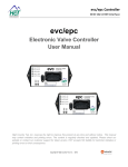
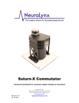
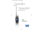
Tetrode Spinner 2.0 User
Manual
Digital Spin Counter for Spinning Custom Tetrodes
ã Neuralynx, Inc.
105 Commercial Drive, Bozeman, MT 59715
Phone 406.585.4542 • Fax 406.585.9034
www.Neuralynx.com
Revision 1.2
[email protected]/24/2012
Table of Contents
1
2
3
4
5
6
7
8
9
Document Overview ................................................................................................ 3
Tetrode Spinner 2.0 Overview ................................................................................. 3
Glossary .................................................................................................................. 3
Unpacking ............................................................................................................... 4
Hardware Overview ................................................................................................. 4
LCD Contrast Adjustment ....................................................................................... 6
Installing the USB Drivers ....................................................................................... 6
Setting Up the Terminal Window............................................................................. 7
Modes of Operation ................................................................................................. 9
9.1
Manual Mode Controlled with Spinner .......................................................... 9
9.2
Manual Mode Controlled with Computer ....................................................... 9
9.3
Auto Mode Controlled with Spinner ............................................................ 10
9.3.1 1 Custom.................................................................................................. 10
9.3.2 2 Load ...................................................................................................... 11
9.3.3 3 Save ...................................................................................................... 11
9.3.4 4 Settings ................................................................................................. 12
9.4
Auto Mode Controlled with Computer ......................................................... 13
9.4.1 1 Custom.................................................................................................. 13
9.4.2 2 Load ...................................................................................................... 14
9.4.3 3 Save ...................................................................................................... 14
9.4.4 4 Settings ................................................................................................. 14
10 Appendix ............................................................................................................... 15
10.1
Setting up the Terminal Window Initially .................................................... 16
List of Figures and Tables
Figure 6-1 Tetrode Spinner Top....................................................................................... 5
Figure 6-2 Tetrode Spinner Back ..................................................................................... 5
Figure 8-1 Driver Installation Window ............................................................................ 6
Figure 8-2 Found New Hardware .................................................................................... 7
Figure 9-1 COM Port Number ......................................................................................... 7
Figure 9-2 Terminal Window Setup................................................................................. 8
Figure 9-3 Terminal Window Auto Mode Choices .......................................................... 8
Figure 10-1 Terminal Window Manual Mode .................................................................. 9
Figure 10-2 Terminal Window Auto Mode .................................................................... 13
Revision 1.2
Tetrode Spinner 2.0 User Manual5/24/2012
Page 2
1 Document Overview
The document will give an overview of the Tetrode Spinner 2.0. It will outline its modes
of operation and its controls. For information and techniques on spinning tetrodes refer to
the Tetrode Assembly Station User Manual found at the Neuralynx website.
2
Tetrode Spinner 2.0 Overview
The Tetrode Spinner 2.0 is a digital spin counter used to for spinning custom tetrodes. It
boasts more features than the original Tetrode Spinner along with a faster and quieter
motor. The Tetrode Spinner 2.0 can be used in two modes; Manual Mode and Auto Mode.
Manual Mode is an exact match to the functionality of the original Tetrode Spinner. This
mode requires the user to constantly watch the Spinner until spinning is complete. Auto
Mode allows the user to move on to other tasks while the Spinner operates. The ability to
save and load "Custom Spin Configurations" has also been added. This will allow the
user to create more consistent tetrodes faster. The Tetrode Spinner 2.0 can also be
controlled via a computer and Terminal Window through a USB connection. The device
can be powered by and internal 9V battery or an external 12V supply, both of which are
provided by Neuralynx.
3 Glossary
Auto Mode – A new feature to the Tetrode Spinner 2.0, this mode allows the user to save
and load Custom Spin Configurations and let the spinner run unsupervised.
CCW – Counter-Clockwise
CW – Clockwise
Custom Spin Configuration – A file that can be saved or loaded on the Tetrode Spinner
2.0. Contains the Turns Clockwise and Turns Counter-Clockwise information.
LCD Contrast – Difference between light and dark colors on the LCD Screen.
Manual Mode – In this mode the Tetrode Spinner 2.0 operates just as the original
Tetrode Spinner. The user is required to change directions and halt manually while the
spinner counts.
Revision 1.2
Tetrode Spinner 2.0 User Manual5/24/2012
Page 3
Terminal Window – An ANSI text only window in a GUI that emulates a console.
4 Unpacking
The Tetrode Spinner 2.0 is shipped with a 12V 1.5A power supply and a USB Cable. The
12V Power Supply comes with multiple heads and can accept a 100VAC to 240VAC input
supply to fit wall outlets worldwide. The USB Cable is a Regular A Male to Mini B Male
cable. The Mini B Male side of the cable will mate with the USB connection on the back
of the Tetrode Spinner 2.0.
5 Hardware Overview
Figures and descriptions of the Tetrode Spinner 2.0 Hardware are shown below.
Revision 1.2
Tetrode Spinner 2.0 User Manual5/24/2012
Page 4
Figure 5-1 Tetrode Spinner Top
Figure 5-2 Tetrode Spinner Back
Power Switch – Used to turn the Tetrode Spinner 2.0 on and select the Mode.
Joystick – Used to control the Tetrode Spinner 2.0 once it has been turned on.
LCD Screen – An information display device.
Spinner Dowel – Interfaces magnetically to the tetrode wire clip for spinning a
terode. Connected to the motor that spins CW and CCW.
5. Power Indicator – Turns Green when the Tetrode Spinner 2.0 has been turned
on.
6. Spinning Indicator – Turns Amber or Red when the motor of the Tetrode
Spinner 2.0 is spinning.
7. LCD Contrast – On the back side of the case. Used for adjusting the contrast
of the LCD Screen.
1.
2.
3.
4.
Revision 1.2
Tetrode Spinner 2.0 User Manual5/24/2012
Page 5
8. USB Connection – On the back side of the case. Used to connect the Tetrode
Spinner 2.0 to a computer for computer control or updates.
9. External Power Connection – Used for hooking the Tetrode Spinner 2.0 to a
wall outlet. Only use the 12V 1.5A supply that came with the product or an
equivalent power source.
6 LCD Contrast Adjustment
The contrast of the LCD Screen can be adjusted by rotating the gold screw head below
the LCD Contrast label on the back of the Tetrode Spinner 2.0 clockwise or counterclockwise. This can be especially useful as the battery begins to diminish.
7 Installing the USB Drivers
Computer control over the Tetrode Spinner 2.0 is accomplished via a Virtual COM Port
and a USB to Serial UART IC in the device. The drivers for the Virtual COM Port can be
found at the Neuralynx website under the Software Section.
Once the driver package has been downloaded the drivers for the Virtual COM Port can
be found in the Folder labeled USB Drivers. Install the drivers by running the
CDMXXXXX_Setup.exe file. The window in the figure below will appear.
Figure 7-1 Driver Installation Window
It may take a few minutes to install the drivers. When it is finished make sure the window
states: "FTDI CDM Driver Installation process completed." Once the drivers have been
installed the window will close itself.
You can now attach the Tetrode Spinner 2.0 to your computer with the USB Cable and
turn the Spinner ON in Auto Mode. After cycling through some Found New Hardware
popups the popup shown in the following figure will appear confirming the driver was
installed properly.
Revision 1.2
Tetrode Spinner 2.0 User Manual5/24/2012
Page 6
Figure 7-2 Found New Hardware
8 Setting Up the Terminal Window
A free Terminal Window is also included in the driver package. This can be found in the
root folder of the package labeled Shortcut to Tetrode Spinner Terminal Window.exe.
Before opening the Terminal Window the COM Port Number must first be found. Do this
by opening the Device Manager and expanding the Ports(COM and LPT) tab. Open the
Device Manager by right-clicking on the My Computer Icon followed by selecting
Properties then selecting the Hardware Tab and finally clicking Device Manager. The
COM Port Number will be listed after the USB Serial Port. The COM Port Number of the
figure below is COM7.
Figure 8-1 COM Port Number
Now that the COM Port Number has been obtained the Terminal Window can be
configured. Do this by opening the File Tetrode Spinner Terminal Window.exe found in
the PuTTY Folder. The window in the following figure will appear. If this is the first time
running Tetrode Spinner Terminal Window.exe or the window does match the following
figure refer to the Appendix.
Revision 1.2
Tetrode Spinner 2.0 User Manual5/24/2012
Page 7
Figure 8-2 Terminal Window Setup
Enter the COM Port Number found earlier into the text box below Serial Line. Select
Default Settings under Saved Sessions and click Save. Click Cancel when finished. The
Terminal Window has now been configured.
Now open Shortcut to Tetrode Spinner Terminal Window.exe in the root folder. Press
Enter on the Keyboard, the Terminal Window should display the Auto Mode choices as
shown in the figure below. If the Terminal Window does match the figure below the
Terminal Window has been configured properly.
Figure 8-3 Terminal Window Auto Mode Choices
Revision 1.2
Tetrode Spinner 2.0 User Manual5/24/2012
Page 8
9 Modes of Operation
Both modes of operation are fully functional using the controls on the Tetrode Spinner
2.0 or a computer. Both control techniques will be discussed in the sections below.
9.1 Manual Mode Controlled with Spinner
Set the Tetrode Spinner 2.0 to Manual Mode by moving the Power Switch to the Manual
Position. The LCD Screen will display the Motor's State and the Counts Left and Counts
Right. The Joystick has 4 functions in this mode; Turn Right, Turn Left, Halt, and Reset
and Halt. The 5 positions of the Joystick and their operations are listed below.
· Left – Motor begins rotating Left(CCW). The L number on the LCD Screen
begins to increment.
· Right – Motor begins rotating Right(CW). The R number on the LCD Screen
begins to increment.
· Up – The Motor stops rotating.
· Down – The Motor stops rotating.
· In(Push) – The Motor stops rotating and both L and R numbers are reset to
zero.
Pushing the joystick in one of these directions will immediately make the change.
9.2 Manual Mode Controlled with Computer
Set the Tetrode Spinner 2.0 to Manual Mode by moving the Power Switch to the Manual
Position and open the Terminal Window(Shortcut to Tetrode Spinner Terminal
Window.exe). The Terminal Window should display the directions as shown in the figure
below.
Figure 9-1 Terminal Window Manual Mode
The numbers were chosen so that the Number Pad could match the Joystick. The 5
positions of the Number Pad and their operations are listed below.
Revision 1.2
Tetrode Spinner 2.0 User Manual5/24/2012
Page 9
·
4 (Left) – Motor begins rotating Left(CCW). The L number on the LCD
Screen begins to increment.
· 6 (Right) – Motor begins rotating Right(CW). The R number on the LCD
Screen begins to increment.
· 8 (Up) – The Motor stops rotating.
· 2 (Down) – The Motor stops rotating.
· 5 (In) – The Motor stops rotating and both L and R numbers are reset to zero.
Pushing one of these keys will immediately make the change
9.3 Auto Mode Controlled with Spinner
Set the Tetrode Spinner 2.0 to Auto Mode by moving the Power Switch to the Auto
Position. The LCD Screen will display four different choices; Custom, Load, Save, and
Settings. The LCD Cursor blinks over the choice currently selected. Move the cursor to
the other choices by pushing the Joystick Up and Down. The four different choices are
discussed separately in the sections below.
9.3.1 1 Custom
Custom allows the user to input the numbers of turns right and left and let the Spinner run
by itself. To select Custom move the cursor to the number 1 by pushing the Joystick Up
and Down and press the Joystick In.
The LCD Screen will change and ask for the number of turns right. Increase and decrease
the displayed number by pushing the Joystick Up and Down respectively. When the
desired number has been reached push the Joystick In. The LCD Screen will change and
ask for the number of turns left. Increase and decrease the displayed number by pushing
the Joystick Up and Down respectively. When the desired number has been reached push
the Joystick In.
The LCD Screen will display "Press center to begin." The next time the Joystick is
pushed In the motor will begin rotating right. It will continually update the LCD when a
full rotation has been completed. When the motor has finished rotating right the Spinner
will beep and halt and the LCD Screen will display "Press center to continue." The next
time the Joystick is pushed in the motor will begin rotating left. It will continually update
the LCD when a full rotation has been completed. When the motor has finished rotating
left the Spinner will beep twice and halt and the LCD Screen will display "Center to Cont.
Left to Quit." If the Joystick is pushed In the Spinner will immediately loop back and
begin rotating right. If the Joystick is pushed Left the Spinner will return to the Main
Screen.
There are three extra Joystick functions that can be performed while the in this mode.
· Left – Return to Main Screen(Exit).
· Right – Pause(Halt Motor).
· In(Push) – Continue(Restart Motor).
Revision 1.2
Tetrode Spinner 2.0 User Manual5/24/2012
Page 10
9.3.2 2 Load
Load allows the user to load a Custom Spin Configuration from memory. To select Load
move the cursor to the number 2 by pushing the Joystick Up and Down and press the
Joystick In.
The LCD screen will change and display Custom Spin File rotation numbers. There are
nine memory slots on the Spinner. Scroll through the memory slots by pushing the
Joystick Up and Down. When the desired memory slot has been reached push the
Joystick In.
The LCD Screen will display "Press center to begin." The next time the Joystick is
pushed In the motor will begin rotating right. It will continually update the LCD when a
full rotation has been completed. When the motor has finished rotating right the Spinner
will beep and halt and the LCD Screen will display "Press center to continue." The next
time the Joystick is pushed in the motor will begin rotating left. It will continually update
the LCD when a full rotation has been completed. When the motor has finished rotating
left the Spinner will beep twice and halt and the LCD Screen will display "Center to Cont.
Left to Quit." If the Joystick is pushed In the Spinner will immediately loop back and
begin rotating right. If the Joystick is pushed Left the Spinner will return to the Main
Screen.
There are three extra Joystick functions that can be performed while the in this mode.
· Left – Return to Main Screen(Exit).
· Right – Pause(Halt Motor).
· In(Push) – Continue(Restart Motor).
9.3.3 3 Save
Save allows the user to edit the nine memory slots on the Spinner. To select Save move
the cursor to the number 3 by pushing the Joystick Up and Down and press the Joystick
In.
The LCD Screen will change and ask for the number of turns right. Increase and decrease
the displayed number by pushing the Joystick Up and Down respectively. When the
desired number has been reached push the Joystick In. The LCD Screen will change and
ask for the number of turns left. Increase and decrease the displayed number by pushing
the Joystick Up and Down respectively. When the desired number has been reached push
the Joystick In.
The LCD screen will change and display Custom Spin File rotation numbers. Scroll
through the memory slots by pushing the Joystick Up and Down. Save the values that
have been entered by scrolling to the desired memory slot and pushing the Joystick In.
The LCD Screen will display "Save successful." and return to the Main Screen. The
entered values have now been saved and can be used through the Load Choice.
Revision 1.2
Tetrode Spinner 2.0 User Manual5/24/2012
Page 11
There is one extra Joystick function that can be performed while the in this mode.
· Left – Return to Main Screen(Exit).
9.3.4 4 Settings
Settings allows the user control over three parts of the Spinner; the Speaker, the LCD
Screen Backlight, and the Cycle Pause. To select Settings move the cursor to the number
4 by pushing the Joystick Up and Down and press the Joystick In.
The LCD Screen will change and display one of three choices. Scroll through the choices
by pushing the Joystick Up and Down. When the desired choice is reached press the
Joystick In.
The LCD will continue to one of the following questions:
1. Do you want the speaker on?
a. The Speaker beeps when the Spinner is finished spinning in the
Custom and Load Choices.
b. Change the cursor from Y[es] to N[o] by pushing the Joystick Up or
Down.
c. When the desired choice has been reached press the Joystick In to
complete the change. The LCD Screen will display "Setting Saved."
and return to the Main Screen.
2. Do you want the backlight on?
a. The LCD Screen Backlight can help in viewing the screen.
b. The Backlight will only turn on if the external power supply is plugged
into the spinner.
c. Change the cursor from Y[es] to N[o] by pushing the Joystick Up or
Down.
d. When the desired choice has been reached press the Joystick In to
complete the change. The LCD Screen will display "Setting Saved."
and return to the Main Screen.
3. Do you want to cycle pause?
a. This controls whether the spinner pauses when it has finished rotating
right in the Custom and Load Choices. If it is set to No the Spinner
will immediately start rotating left when it has finished rotating right.
b. Change the cursor from Y[es] to N[o] by pushing the Joystick Up or
Down.
c. When the desired choice has been reached press the Joystick In to
complete the change. The LCD Screen will display "Setting Saved."
and return to the Main Screen.
There is one extra Joystick function that can be performed while the in this mode.
· Left – Return to Main Screen(Exit).
Revision 1.2
Tetrode Spinner 2.0 User Manual5/24/2012
Page 12
9.4 Auto Mode Controlled with Computer
Set the Tetrode Spinner 2.0 to Auto Mode by moving the Power Switch to the Auto
Position and open the Terminal Window(Shortcut to Tetrode Spinner Terminal
Window.exe). The Terminal Window should display the choices as shown in the figure
below.
Figure 9-2 Terminal Window Auto Mode
9.4.1 1 Custom
Custom allows the user to input the numbers of turns right and left and let the Spinner run
by itself. To select Custom type the number 1.
The Terminal Window will ask for the number of turns right. Enter this number by typing
it. When finished push Enter. The Terminal Window will ask for the number of turns left.
Enter this number by typing it. When finished push Enter.
The Terminal Window will display "Press Enter to continue." The next time Enter is
pushed the motor will begin rotating right. When the motor has finished rotating right the
Spinner will beep and halt and the Terminal Window will display "Press Enter to
continue." The next time Enter pushed the motor will begin rotating left. When the motor
has finished rotating left the Spinner will beep twice and halt and the Terminal Window
will display "Enter to Continue or – to Quit." If Enter is pushed the Spinner will
immediately loop back and begin rotating right. If '-' is pushed the Spinner will return to
the Main Screen.
There are three extra Keyboard functions that can be performed while the in this mode.
· '-' – Return to Main Screen(Exit).
· 'p' – Pause(Halt Motor).
· 'c' – Continue(Restart Motor).
Revision 1.2
Tetrode Spinner 2.0 User Manual5/24/2012
Page 13
9.4.2 2 Load
Load allows the user to load a Custom Spin Configuration from memory. To select Load
type the number 2.
The Terminal Window will display the entire list of Custom Spin Files. There are nine
memory slots on the Spinner. Select the desired memory slot by typing its number.
The Terminal Window will display "Press Enter to continue." The next time Enter is
pushed the motor will begin rotating right. When the motor has finished rotating right the
Spinner will beep and halt and the Terminal Window will display "Press Enter to
continue." The next time Enter is pushed the motor will begin rotating left. When the
motor has finished rotating left the Spinner will beep twice and halt and the Terminal
Window will display "Enter to Continue or – to Quit." If Enter is pushed the Spinner will
immediately loop back and begin rotating right. If '-' is pushed the Spinner will return to
the Main Screen.
There are three extra Keyboard functions that can be performed while the in this mode.
· '-' – Return to Main Screen(Exit).
· 'p' – Pause(Halt Motor).
· 'c' – Continue(Restart Motor).
9.4.3 3 Save
Save allows the user to edit the nine memory slots on the Spinner. To select Save type the
number 3.
The Terminal Window will ask for the number of turns right. Enter this number by typing
it. When finished push Enter. The Terminal Window will ask for the number of turns left.
Enter this number by typing it. When finished push Enter.
The Terminal Window will display the entire list of Custom Spin Files. There are nine
memory slots on the Spinner. Select the desired memory slot to save to by typing its
number. The terminal window will display "Save Successful" are return to the Main
Screen.
There is one extra Keyboard function that can be performed while the in this mode.
· Left – Return to Main Screen(Exit).
9.4.4 4 Settings
Settings allows the user control over three parts of the Spinner; the Speaker, the LCD
Screen Backlight, and the Cycle Pause. To select Settings type the number 4.
The Terminal Window will display the three options. Select a option by typing its
number. The Terminal Window will display one of the next three options.
Revision 1.2
Tetrode Spinner 2.0 User Manual5/24/2012
Page 14
1. Do you want the speaker on(y/n)?
a. The Speaker beeps when the Spinner is finished spinning in the
Custom and Load Choices.
b. Type 'y' or 'n' to change the setting. The Terminal Window will display
"Setting Saved." and return to the Main Screen.
2. Do you want the backlight on(y/n)?
a. The LCD Screen Backlight can help in viewing the screen.
b. The Backlight will only turn on if the external power supply is plugged
into the spinner.
c. Type 'y' or 'n' to change the setting. The Terminal Window will display
"Setting Saved." and return to the Main Screen.
3. Do you want to cycle pause(y/n)?
a. This controls whether the spinner pauses when it has finished rotating
right in the Custom and Load Choices. If it is set to No the Spinner
will immediately start rotating left when it has finished rotating right.
b. Type 'y' or 'n' to change the setting. The Terminal Window will display
"Setting Saved." and return to the Main Screen.
There is one extra Keyboard function that can be performed while the in this mode.
· Left – Return to Main Screen(Exit).
10 Storing the Tetrode Wire Clip
When not using the Tetrode Spinner the Tetrode Wire Clip should be attached to the
Spinner Dowel. Be sure to match the painted side of the Tetrode Wire Clip with the
painted magnet on the Spinner Dowel. Not doing so could affect the quality of the
magnets.
Revision 1.2
Tetrode Spinner 2.0 User Manual5/24/2012
Page 15
11 Appendix
11.1 Setting up the Terminal Window Initially
Following the following steps to initially setup the PuTTY Terminal Program.
1. Select the Session Category.
2. Select Serial under "specify the destination you want to connect to."
3. Enter the COM Port Number found earlier into the text box below Serial Line.
4. Select the Sub-Category Keyboard under the Terminal Category.
5. Select Control-H under "The Backspace key."
6. Select the Window Category.
7. Enter 45 into the text box under Columns.
8. Enter 20 into the text box under Rows.
9. Select the Serial Category.
10. Set the Speed to 9600.
11. Set the Data Bits to 8.
12. Set the Stop Bits to 1.
13. Set the Parity to None.
14. Set the Flow Control to None.
15. Return to the Session Category.
16. Select Default Settings under "Load, save or delete a stored session."
17. Click Save.
18. Click Cancel.
The Terminal Window should now be properly configured. These steps only need to be
preformed once as long as the session is saved.
Revision 1.2
Tetrode Spinner 2.0 User Manual5/24/2012
Page 16